

Page 1
Installation and
operating instructions
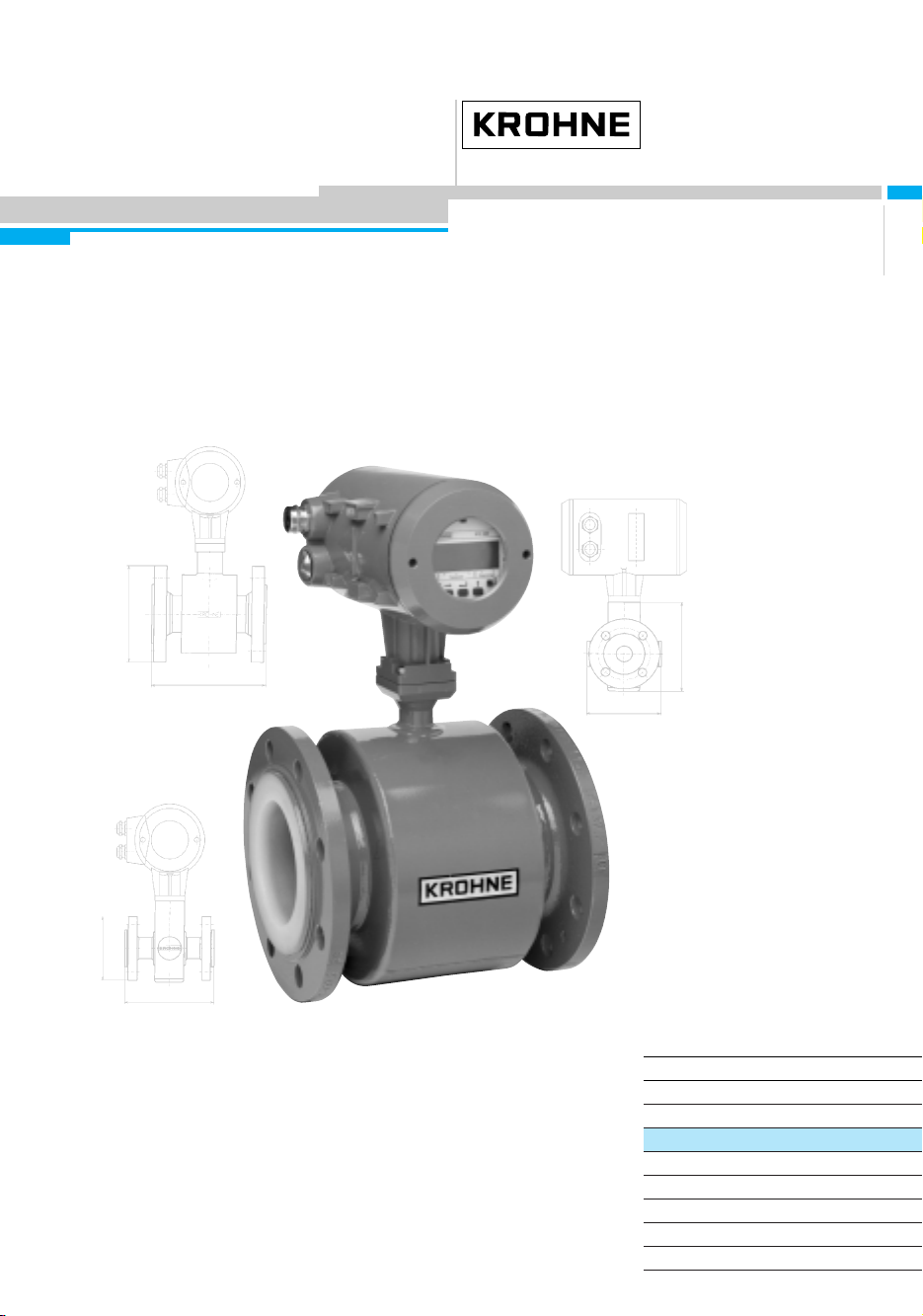
ALTOFLUX 2W
IFM 4042 K
Electromagnetic flowmeters
Variable area flowmeters
Vortex flowmeters
Flow controllers
Electromagnetic flowmeters
Ultrasonic flowmeters
Mass flowmeters
Level measuring instruments
Communications engineering
Engineering systems & solutions
Applicable to
Software Versions
● Display/Control unit
No. 3.19019.xx00
● ADC module
No. 3.19749.xx00
● I/O module
No. 3.18748.xx00
DIN A4: 7.10004.31.00
©
KROHNE 02/2001 US size: 7.10004.71.00
GR/OP
How to use these Instructions
The flowmeters are supplied ready for operation.
– Installation in the pipeline (Section 1) Pages 5-10
– Electrical connection (Section 2) Pages 11-13
– Start-up (Section 3) Page 17
Power the flowmeter. THAT’S ALL. The system is operative.
Page 2
<RXURSHUDWLQJGDWD
Here you can note down the settings of the signal converter !
Fct. No. Function Settings
1.01 Full-scale range
1.02 Time constant
1.03 Low-flow cutoff - ON: - OFF:
1.04 Display
1.05 Current output
Flow
Counter
Messages
Function
Range
Error
1.06. Pulse output
Function
Pulse width
Pulses / Volume
1.07 Status output
3.01 Language
3.02 Primary head Meter size
GKL value
Flow direction
3.4 Application Empty pipe
Field current
Mode field current
Limit
Filter
3.5 Hardware Function of terminal B:
3.6 HART
off HART
Current 4 mA trim.:
Current 20 mA trim.:
Address
I-Multidrop:
2
ALTOFLUX 2W
02/2001
Page 3

&RQWHQWV
•
•
•
•
•
Your operatig data 2
System description 4
Product liability and warranty 4
CE / EMC / Standards / Approvals 4
Software history 4
7HLO$ ,QVWDOODWLRQDQG6WDUWXS
1 Installation 5 - 10
1.1 Items included with supply 5
1.2 Handling 5
1.3 Installation location 6
1.4 Suggestions for installation 7
1,5 Installation in the pipeline 8
1.6 Torques 9
1.7 Grounding 10
2 Electrical connection 11 – 16
2.1 Information on electrical connection and connection data 11
2.2 Output circuit diagrams 12 – 13
2.3 Characteristic of the outputs 14 – 16
3 Start-up 17
3.1 Power ON and measurement 17
3.2 Factory settings 17
7HLO% ,)&6LJQDOFRQYHUWHU ²
4 Operation of the signal converter 18 - 33
4.1 KROHNE operator control concept 18
4.2 Operating and check elements 19
4.3 Function of keys 20 – 21
4.4 Table of settable function 22 – 32
4.5 Error messages in measuring mode 33
4.6 Reset counter and cancel error messages 33
7HLO& 7HFKQLFDO'DWD%ORFNGLDJUDPXQG0HDVXULQJSULQFLSOH ²
5 Technical Data 34 - 40
5.1 Full-scale ranges 34
5.2 Error limits at reference conditions 35
5.3 IFC 040 Signal converter 36 – 37
5.4 IFS 4002 Primary head 38
5.5 Dimensions and weights 39
5.6 Limits 40
6 Block diagram of signal converter 41
7 Measuring principle 42
8 If you need to return flowmeters for testing or repair to KROHNE 43
02/2001
ALTOFLUX 2W
3
Page 4

6\VWHPGHVFULSWLRQ
ystem description
Electromagnetic 2-wire flowmeters with IFC 040 signal converter are precision instruments
designed for linear flow measurement of liquid products.
The process liquids need to be electrically conductive, ≥ 5 µS/cm
(for cold demineralized water ≥ 20 µS/cm).
Depending on the meter size, the full-scale range Q
100%
can be set between 85 Liter/h and 763 m3/h, equivalent to a flow velocity v = 0,3- 12 m/s,
see flow table in Section 5.1.
3URGXFWOLDELOLW\DQGZDUUDQW\
Electromagnetic 2-wire flowmeters with IFC 040 signal converter are designed solely for
measuring the volumetric flowrate of electrically conductive, liquid process products.
These flowmeters are also available for use in hazardous areas. Special codes and regulations
apply in this connection and these are referred to in the special ‘EEx’ notes.
Responsibility for suitability and intended use of these electromagnetic flowmeters rests solely
with the operator.
Improper installation and operation of the flowmeters (systems) may lead to loss of warranty.
In addition, the “General conditions of sale” forming the basis of the purchase contract are
applicable.
If flowmeters need to be returned to KROHNE, please note the information given on the last-but-
one page of these Instructions. KROHNE regret that they cannot repair or check your
flowmeter(s) unless accompanied by the completed form sheet.
&((0&6WDQGDUGV$SSURYDOV
Electromagnetic flowmeters with IFC 040 signal converter
meet the protection requirements of Directive 89/336/EEC in conjunction with
EN 50081-1 (1992) and EN 50082-2 (1995), and Directives 73/23/EEC and
93/68/EEC in conjunction with EN 61010-1, and also bear the CE symbol..
6RIWZDUHKLVWRU\
Display and control unit PC user software Hart® module
IFC 040 IFC 040
Software Status Software Status Software Status
3.19019.xx00 current 3.19136.xx00 current 3.18748.xx00 current
ADC module I/O module
Software Status Software Status
3.19749.xx00 current 3.18748.xx00 current
4
ALTOFLUX 2W
02/2001
Page 5
Part A Installation and Start-up Section 1.1 + 1.2
,QVWDOODWLRQ
1.1 Items included with supply
Flowmeter in the size as ordered
•
Connecting wires for grounding, refer to Section 1.7 Grounding
•
Certificate of calibration data
•
Grounding rings (option), if ordered
•
Installation and operating instructions for the signal converter
•
Fitting accessories (stud bolts, screws, gaskets, etc.)
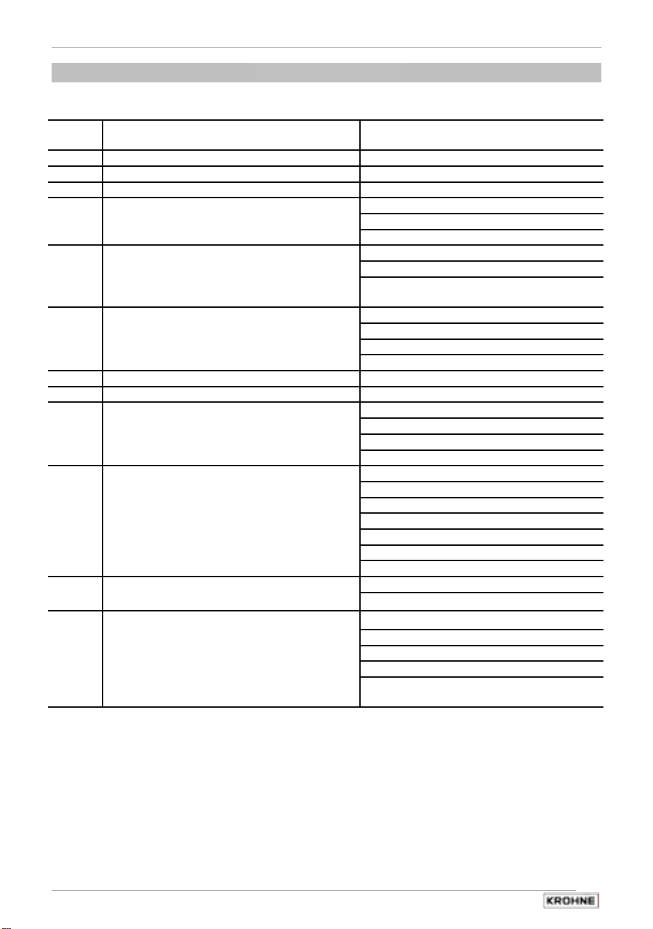
1.2 Handling
to be provided by customer!
are not supplied,
Do not lift flowmeter by the signal converter
housing or the terminal box.
Do not set flowmeter down on the signal
converter housing.
02/2001
ALTOFLUX 2W
5
Page 6
Section 1.3 Part A Installation and Start-up
1.3 Installation location
• Temperatures
Refer to Section 5.6 “Limits“ for operating pressure and vacuum load based on flange
standards and type of tube liner.
Standard -25 to +60 °C -13 to +140 °F
EEx -25 to +60 °C -13 to +140 °F
Storage and handling -25 to +60 °C -13 to +140 °F
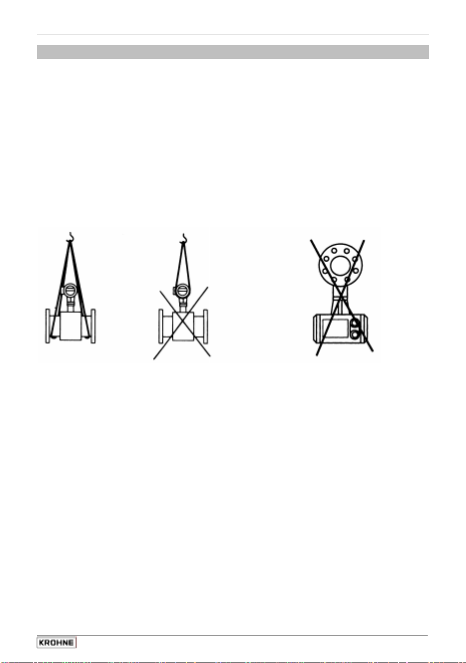
• Location and position as required,
but in a horizontal pipe run
electrode axis
Ambient temperature
-25 to +40 °C -13 to +104 °F
-25 to +40 °C -13 to +104 °F
Process temperature
-25 to ≤ + 60 °C -13 to ≤ +140 °F
-25 to ≤ +140 °C -25 to ≤ +284 °F
-25 to ≤ + 60 °C -13 to ≤ +140 °F
-25 to ≤ +140 °C -25 to ≤ +284 °F
X – • – • – • – X
should be approximately horizontal.
Y Signal converter housing
• Measuring tube must be completely filled at all times.
• Direction of flow is arbitrary: arrow on flowmeter can normally be ignored.
For exceptions, refer to Sect. 3.2 “Factory settings” in the Installation and Operating
Instructions for the signal converter.
• Stud bolts and nuts: to install, make sure there is sufficient room next to the pipe flanges.
• Vibration: support pipeline on both sides of flowmeter. Level of vibration in conformity with
IEC 068-2-34: below 2.2g for flowmeters in the 20-150 Hz frequency range.
• Do not expose to direct sunlight: fit a sunshade if necessary, not included with flowmeter,
to be provided by customer.
• Avoid strong electromagnetic fields in vicinity of flowmeter.
• Inlet run 5 × DN and outlet run 2 × DN, straight pipeline,
measured from electrode axis (DN = meter size)
• Vortex and corkscrew flow: increase length of inlet and outlet runs or
install flow conditioners.
• Mixing different process liquids: install flowmeter upstream of the mixing point or at an
adequate distance downstream (min. 30 × DN), otherwise display may be unsteady.
• Plastic pipelines and internally coated metal pipelines: grounding rings required,
refer to Sect. 1.7 “Grounding“.
• Insulated pipeline: do not insulate flowmeter.
• Zero setting: not necessary. To check, it should be possible to set “zero“ flow velocity
when the measuring tube is completely filled. Shutoff valves should therefore be provided,
either downstream of the flowmeter or upstream and downstream of the flowmeter.
• Electrical connection to VDE 0100 “Regulations governing heavy-current installations
with line voltages up to 1000 V” or equivalent national regulations.
• Hazardous areas: subject to special regulations,
refer to special ‘EEx’ information (texts with grey background).
6
ALTOFLUX 2W
02/2001
Page 7
Part A Installation and Start-up Section 1.4
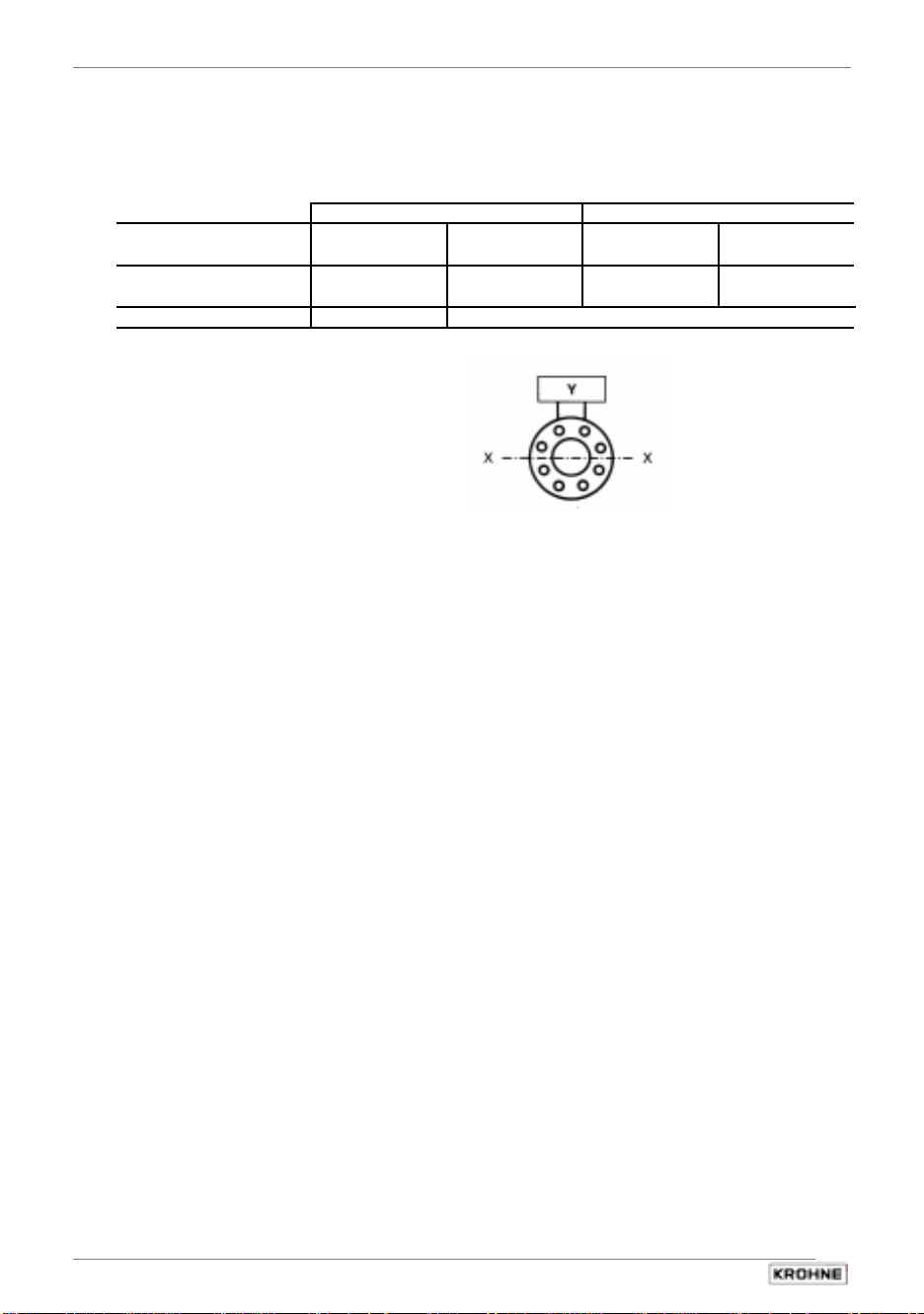
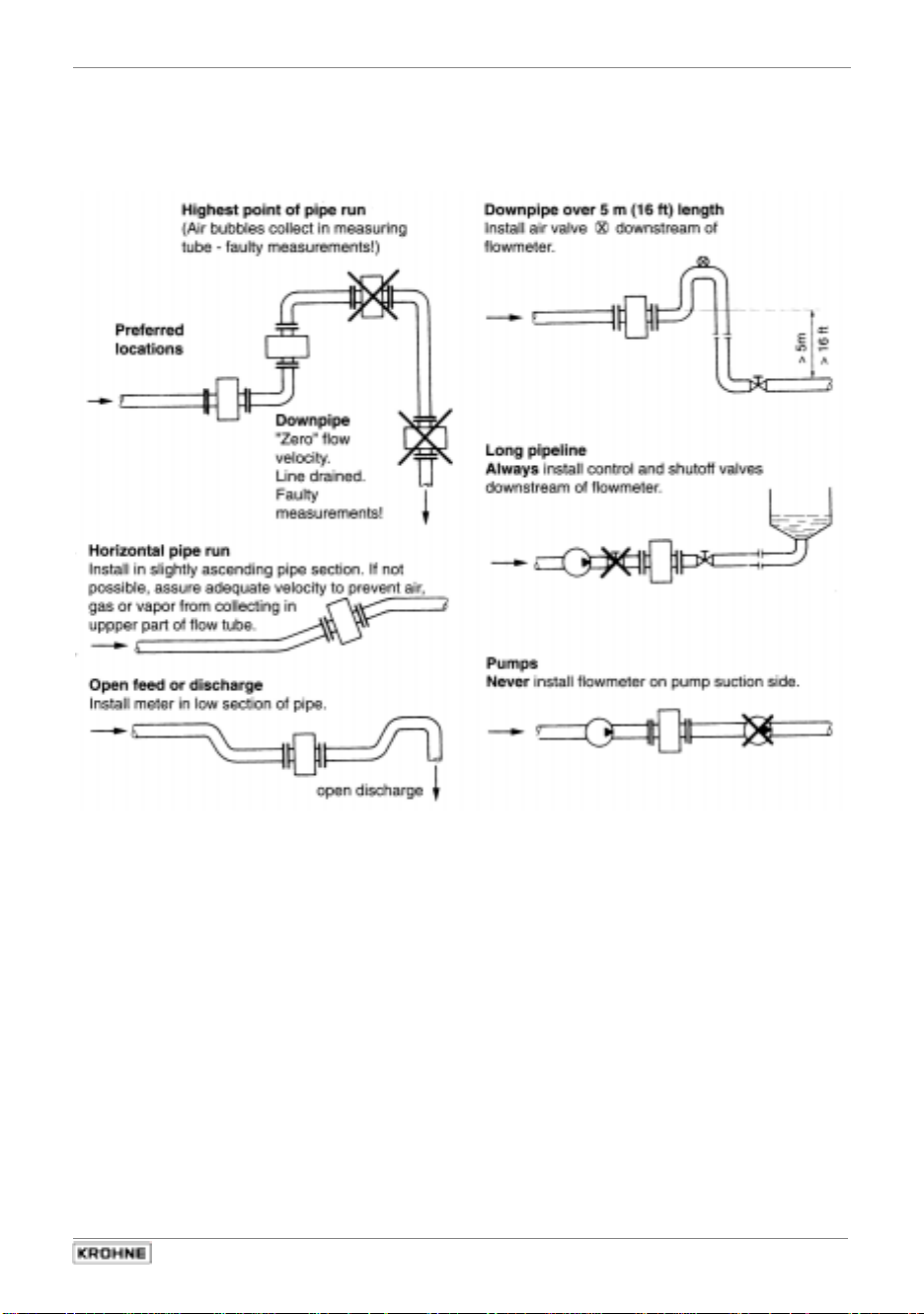
1.4 Suggestions for installation
To avoid measuring errors due to gas/air inclusion or to pipe running empty,
please observe the following:
02/2001
ALTOFLUX 2W
7
Page 8
Section 1.5 Part A Installation and Start-up
1.5 Installation in the pipeline
• Installation material not included, to be provided by customer
(stud bolts, nuts, gaskets, etc.).
• Pipe flanges and operating pressure: refer to “limits“ tables in Section 5.6
• Distance between pipe flanges:
see fitting dimension a in Section 5.5 “Dimensions and weights“
• High-temperature service
Where process temperatures exceed 100°C/212°F, provide facilities to compensate for
longitudinal expansion on heat-up of the pipeline.
For short pipelines, use resilient gaskets, and
for long pipelines install flexible pipe elements (e.g. elbows).
• Flange position: Install flowmeter in line with pipe axis.
Pipe flange faces must be parallel to each other.
• Gaskets
No additional gaskets required for primary heads fitted with tube liners of Teflon® - PFA or
Teflon® - PTFE. Refer to Sect. 1.6 for torques.
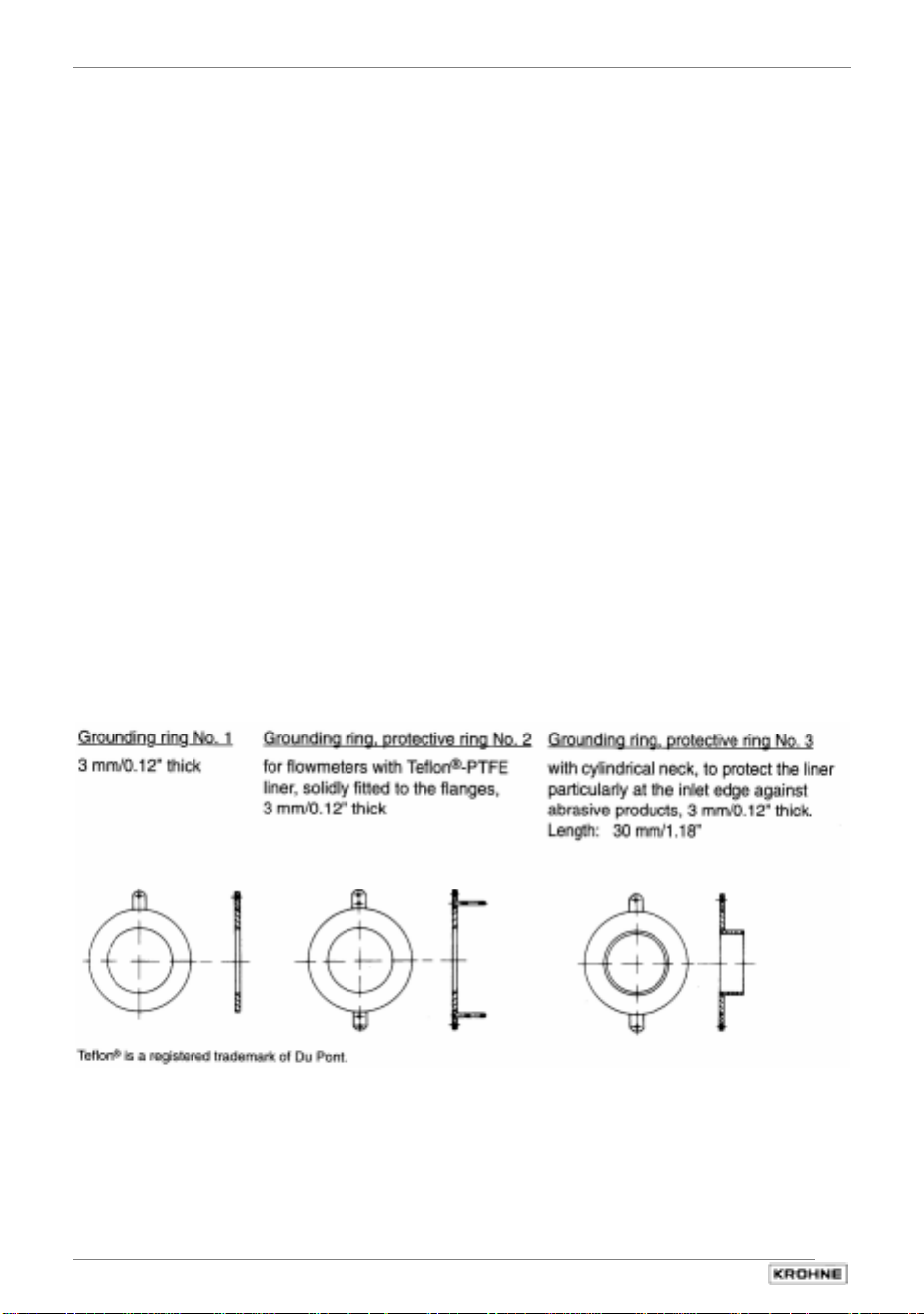
• Grounding rings / protection rings (option)
On plastic pipelines and internally coated metal pipelines, grounding rings are required to
form the conductive connection with the process liquid. Refer to Sect. 7 “Grounding“ for
electrical connection.
Please note: The cylindrical neck must be inside the measuring tube
(to protect the liner, particularly at the inlet edge).
8
ALTOFLUX 2W
02/2001
Page 9
Part A Installation and Start-up Section 1.6
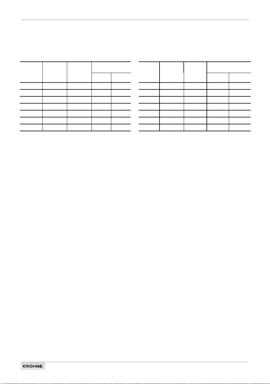
1.6 Torques
• Stud bolts:
See table for number and type.
• 10 Nm ~ 1.0 kpm ~ 7.23 ft × lbf
Meter
size
DN mm
10
15
25
50
80
100
150
tighten uniformly in diagonally opposite sequence.
Pressure
rating
PN
40
40
40
40
25
16
16
Bolts
Max.
torques
Nm
4 × M 12 7.6 5.5
4 × M 12 9.3 6.7
4 × M 12 22
4 × M 16 55
8 × M 16 47
8 × M 16 39
8 × M 20 68
ft × lbf
11
31
25
30
47
Meter
size
inches
3
/
1
/
1
2
3
4
6
Flange
class
Ib
150
8
2
150
150
150
150
150
150
Bolts
for
ANSI
class 150
flanges
4 × 1/2" 3.5
4 × 1/2" 3.5
4 × 1/2" 6.7
4 × 5/8” 24
4 × 5/8” 43
4 × 5/8” 34
8 × 3/4" 61
Nm
Max.
torques
ft × lbf
2.5
2.5
4.8
17.4
31.1
24.6
44.1
02/2001
ALTOFLUX 2W
9
Page 10
Section 1.7 Part A Installation and Start-up
1.7 Grounding
• All flowmeters must be properly grounded to avoid personnel shock hazard.
• The ground conductor should not transmit any interference voltages, therefore do not
ground any other electrical devices together with this conductor.
Repeater power supply unit
• Protective separation (PELV) must be ensured
(VDE 0100 / VDE 0106 or IEC 364 / IEC 536, or equivalent national regulations).
• For measurement reasons, connect an FE functional ground conductor.
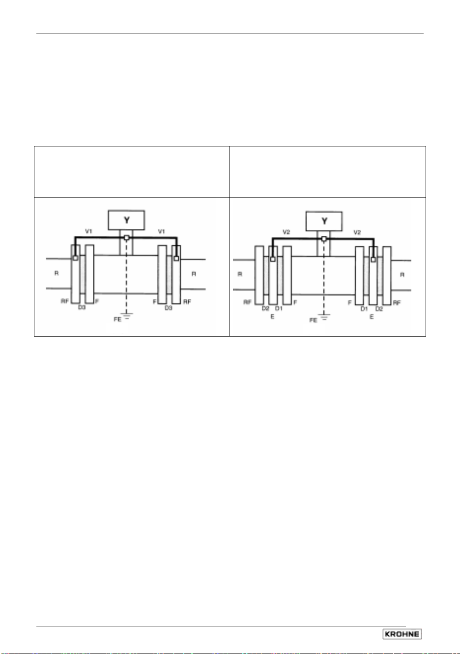
Metal pipelines, not internally coated
Metal pipelines,
with or without internal coating,
and plastic pipelines
grounding without grounding rings
grounding with grounding rings
D1, D2, D3 Gaskets, not included with supply, to be provided by customer.
E Grounding rings (option)
F Flowmeter flanges
FE Functional ground, wire ≥ 4 mm2 Cu (10 AWG), not included with supply,
to be provided by customer.
R Pipeline
RF Pipe flanges
V1, V2 Interconnecting wires, included with supply
Y Terminal box or signal converter
10
ALTOFLUX 2W
02/2001
Page 11
Part A Installation and Start-up Section 2.1
(OHFWULFDOFRQQHFWLRQ
2.1 Information on electrical connection and connection data
• Rated values: The flowmeter housings protect the electronic equipment from dust and
moisture and should always be kept properly closed. Creepage distances and clearances in air
have been dimensioned in conformity with VDE 0110 and IEC 664 for contamination category
2. Supply circuits and output circuits are designed to meet the standards of overvoltage classes
III and II, respectively.
• Safety isolation: The flowmeter must be provided with an isolating facility.
• Note information on instrument nameplate(s).
• PE conductor / FE functional ground must be connected to the separate U-clamp
terminal in the terminal compartment of the signal converter.
• For measurement reasons, the flowmeter must be properly grounded. The ground conductor
should not transmit any interference voltages. Therefore, do not ground any other electrical
devices together with this conductor.
• In hazardous areas, the ground conductor is used simultaneously for equipotential bonding.
CAUTION: Where a power booster (1L= / 0L=) is used, electrical isolation is required
between the power booster and the current output, otherwise the electronic equipment will
substain irreparable damage.
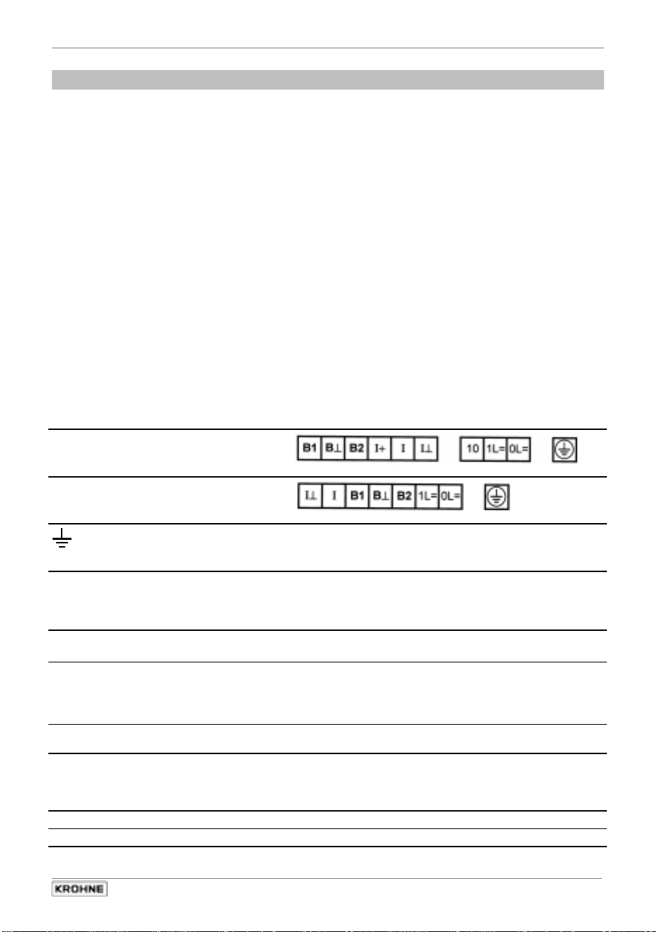
Standard power terminals
EEx power terminals
FE
PE
Current output
Ι
(not polarity sensitive)
Ι ⊥
B 2
Pulse or status output
NAMUR
B ⊥
B 1
Pulse or status output
high current
B ⊥
Functional ground
Safety conductor / equipotential bonding
V
= 36 V Ι
max
V
= 24 V Ι
nom
= 14 V Ι
V
min
NAMUR terminals (B2 + B ⊥)
= 0.4 mA Ι
Ι
open
High-current terminals (B1 + B ⊥)
closed: V
open: V
Common ground (negative) Take note of polarity!
B ⊥
1L=
Power booster
0L=
(not polarity sensitive)
Ι +
2nd power terminal
V
= 36 V V
max
V
= 24 V Ι
nom
not used, no internal connection
10 for internal use only
02/2001
ALTOFLUX 2W
= 22.4 mA (fault current)
max
= 4 - 20 mA
nom
= 3.6 mA (fault current)
min
closed
max
max
V
nom
min
nom
= 6 mA
= 2 V Ι
= 36 V Ι
= 24 V Ι
= 14 V
= 22 mA
max
max
nom
= 100 mA
= 2 mA
= 1,5 mA
11
Page 12
Section 2.2 Part A Installation and Start-up
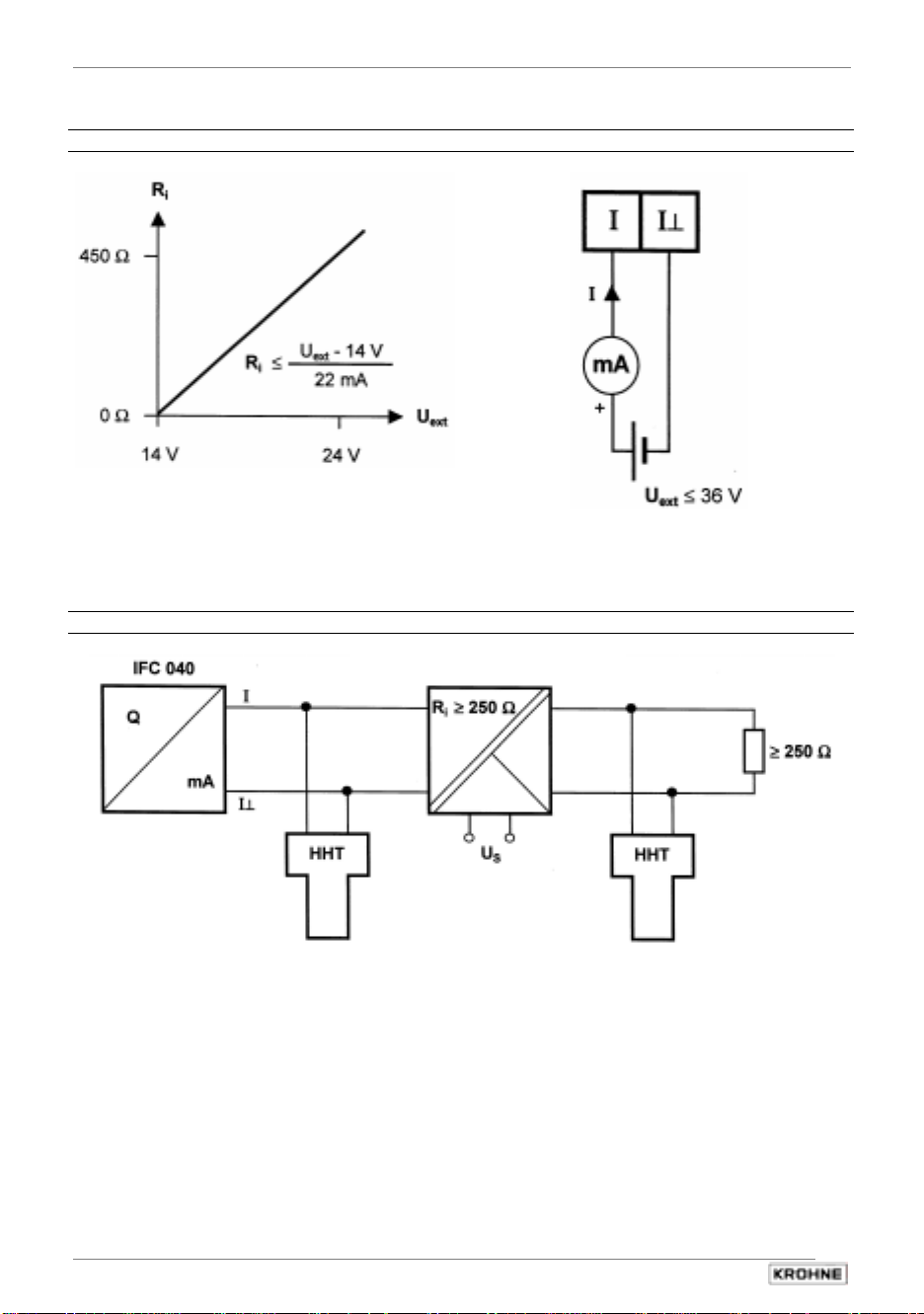
2.2 Output circuit diagrams
Supply power and current output - standard
Note data given in Sect. 2.1!
Supply power and current output - operation via repeater power supply unit
Repeater power supply unit
Repeater power supply unit, e.g.:
CEAG 6 / 420 or
Phoenix Contact PI/Ex-ME-RPSS-I/I Note data given in Sect. 2.1!
12
ALTOFLUX 2W
02/2001
Page 13
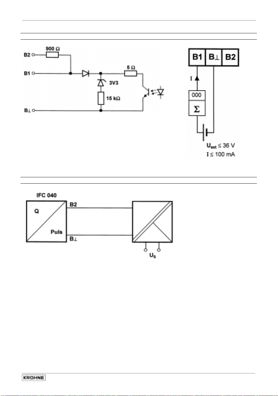
Part A Installation and Start-up Section 2.2
Pulse or status output
current limited
to 100 mA
Note data given in Sect. 2.1!
Pulse or status output - operation via repeater power supply unit
Repeater power supply unit
Repeater power supply unit e.g.:
Phoenix PI/Ex-ME-2NAM/COC Note data given in Sect. 2.1!
02/2001
ALTOFLUX 2W
13
Page 14

Section 2.3 Part A Installation and Start-up
2.3 Characteristic of the outputs
Fig. 1 Low-flow cutoff SMU (see Fct. 1.3 in Section 4.4)
I,P,S,..
-2.Number
-1.Number
L. F. Cutoff
Q
1.Number
2.Number
Fig. 2 Current output (see Fct. 1.5 in Section 4.4)
positive
direction
-Q
100%
negative
direction
I
100%
I,P
I,P
absolute
I
100%
I
0%
0
Q
Q
100%
-Q
100%
I,P
I
100%
I
0%
0
Q
negative-zero-positive
I
I
0%
100%
Q
0
Q
100%
I
I
0%
0
Q
Q
100%
14
ALTOFLUX 2W
02/2001
Page 15

Part A Installation and Start-up Section 2.3
Fig. 3 Pulse output
positive
direction
negative
direction
-Q
100%
(see Fct. 1.6 in Section 4.4)
I,P
I
100%
I
0%
0
I,P
I
100%
I
0%
0
Q
Q
100%
Q
-Q
100%
absolute
I
100%
I
I,P
0%
0
Q
Q
100%
Fig. 4 Status output: Automatic range change BA
I
I
100%
I
0%
-Q
100%
02/2001
-Limit
Limit
S
closed
ALTOFLUX 2W
Q
Q
100%
Qopen
(see Fct. 1.7 in Section 4.4)
15
Page 16

Section 2.3 Part A Installation and Start-up
Fig. 5 Status output: Limit switches
(see Fct. 1.7 in Section 4.4)
S
closed
open
-off limit
-on limit
off limit
on limit
Q
-on limit
Fig. 6 Noise / Change of flow (see Fct. 3.4 in Section 4.4)
Noise without Noise Filter
Flow Change
Noise Level
-off limit
S
closed
open
on limit
off limit
Q
Noise
-Noise Flow
0
Noise
Noise Flow
Fig. 7 Pulse duration (see Fct. 3.4 in Section 4.4)
Q
Pulse Width
16
ALTOFLUX 2W
Q
t
02/2001
Page 17

Part A Installation and Start-up Section 3.1+ 3.2
6WDUWXS
3.1 Power ON and measurement
• Before powering the system, please check that it has been correctly installed according to
Sections 1 and 2.
• The flowmeter is delivered ready for operational use. All operating data have been factory-
set in accordance with your specifications.
Please also refer to Section 3.2 “Factory settings”.
• Power the unit, and the flowmeter will immediately start process flow measurements.
• When powered, the display shows in succession: START UP and READY. This is followed by
indication of the current flow rate and/or the current counter count, on either a continuous or
alternating basis, depending on the setting under Fct. 1.04.
• For operator control, refer to Section 4.
3.2 Factory settings
All operating data are factory set according to your order specifications.
If you have not made any particular specifications at the time of ordering, the devices are
delivered with the standard parameters and functions listed in the table below.
To facilitate easy and rapid start-up, the current output is set to process flow measurement in
“absolute“, so that the current flow rate is displayed independent of the direction of flow. On the
display, measured values may possibly be shown with a “ - ” sign.
This factory setting for the current output may possibly cause measuring errors:
For example, when pumps are switched off and a “backflow“ occurs that is not within the range
of the low-flow cutoff SMU, or when separate displays and counts are required for both flow
directions.
To avoid faulty measurements, therefore, it may be necessary to change the factory setting of
some or all of the following functions. For operator control see Section 4.4:
• Low-flow cutoff SMU, Fct. 1.03
• Display, Fct. 1.04
• Current output, Fct. 1.05
• Pulse output, Fct. 1.06
Standard factory settings
Function Setting Function Setting
1.01 Full scale range Q
1.02 Time constant 3,0 s
1.03 Low-flow cutoff OFF: 0,4 % 3.01 Language English
1.04 Display Meter size see nameplate
Flow rate Percent Flow direction
Counter m3 (see arrow on primary head) Pos. flow
1.05 Current output 3.04 Application
Function Absolute Empty pipe yes
Range 4 - 20 mA Field current 100-50-25 mA
Error message 22 mA Mode field current two times
1.06 Pulse output Limit 150 %
Function off Filter off
Pulse per volume 1 Pulse / m3
Pulse width 50 ms 3.06 HART no
02/2001
100%
see nameplate 1.07 Status output off
ON: 0,5 % 3.02 Primary head
3.05 Hardware Pulse output
ALTOFLUX 2W
17
Page 18

Section 4.1 Part B IFC 040 Signal converter
2SHUDWLRQRIWKHVLJQDOFRQYHUWHU
4.1 KROHNE operator control concept
136.49 Measuring mode
m3/h
→
↵
Menu column Function column Data column
4.2 COUNTER RESET
4.0 RESET 4.1 ERROR RESET
3.6 HART
3.5 HA RDWARE
3.4 APPLICATION
3.3 ZERO SET
3.2 FLOW METER
Direction of
movement
3.0 INSTALLATION 3.1 LANGUAGE
2.2 HARDWARE INFO
2.0 TEST 2.1 TEST Q
1.7 STATUS OUTPUT
1.6 PULSE OUTPUT
CURRENT OUTPUT
1.5
1.4 DISPLAY
1.3 L.F.CUTOFF
1.2 TIME CONSTANT
1.0 OPERATION 1.1 FULL SCALE
↑
→
↑
↵ ↵
→
see
Section
4.4
18
ALTOFLUX 2W
02/2001
Page 19

Part B IFC 040 Signal converter Section 4.2
4.2 Operating and check elements
Control by way of ...
5
...
the 3 keys
, after twisting off the cover of
the electronics compartment using the
special wrench (supplied).
...
the 3 magnetic sensors
and the bar
magnet (supplied) without opening the
housing.
Flow
rate
IFC 090 D
IFC 040
16
2
3
+
Totalizer
m3/h
-
4
I
Overange
P
PLEASE NOTE !
Do not damage the screw thread and gasket of the cover, never allow dirt to accumulate, and
make sure they are well greased at all times.
Replace any damaged gasket immediately!
Display 1st line
Display 2nd line 4-character light writing
Display 3rd line Arrows to identify display
Flowrate
Counter
Overrange
+
-
Σ
Ι
P
Current flow rate
Positive counter
Negative counter
Sum counter (+ and -)
Overranging, current output
Overranging, pulse output
Keys for operator control of signal converter
Magnetic sensors to set the converter by means of a handheld bar magnet without
opening the housing.
Function of sensors same as keys
02/2001
ALTOFLUX 2W
19
Page 20

Section 4.3 Part B IFC 040 Signal converter
4.3 Function of keys
The cursor, flashing part of display or horizontal scrolling, has a grey background.
To start operator control
Measuring mode Operator control mode
13.57 1 FCt. 1. 0
m3 / h O P E R A T I O N
To select function
Increase number = select next function
FCt. 1.4 FCt. 1.5
D I S P L A Y C U R R E N T O U T P U T
To transfer to subfunction
→
↑
FCt. 1.5 info
C U R R E N T O U T P U T F U N C T I O N
To transfer to setting of subfunction
info Edit
F U N C T I O N P o S . d i r e c t i o n
To alter texts
When (e.g. flow) units are changed, the numerical value is converted automatically.
Edi t Edi t
P o S . d i r e c t i o n N e G . d i r e c t i o n
To transfer to next subfunction
Edi t i nfo
N e G . d i r e c t i o n 0 P e R . C u R R e n t
To transfer to setting of subfunction
→
↵
↑
↵
info 0 4. 0
0 P e R . C u R R e n t mA
20
↵
ALTOFLUX 2W
02/2001
Page 21

Part B IFC 040 Signal converter Section 4.3
To move cursor
To change a number
To terminate operator control
Press key
1.0 OPERATION, 2.0 TEST
is displayed.
(flashing position)
each keystroke moves 1 place to the right
0 4. 0 0 4. 0
0 4. 005. 0
repeatedly until one of the functions
↵
or
FCt. 3. 0End
I N S T A L L A T I O N Y E S
Store new parameters
→
mA mA
↑
mA mA
3.0 INSTALLATION
↵
Press key ↵ to confirm “
continued with the new parameters.
”, measuring mode
YES
Do not store new parameters
02/2001
Press key ↵ to confirm “NO”, return to Fct.
1.0 OPERATION
ALTOFLUX 2W
21
Page 22

Section 4.4 Part B IFC 040 Signal converter
4.4 Table of settable functions
Display texts
FCt. 1.1
FULL SCALE
XXX.XXX
↑ "user unit"
Range:
0.3-12 m/s = 1-40 ft/
FCt. 1.2
TIME CONSTANT
XX.X
Range 0.5 ... 99.9s
Standard 3.0s
FCt. 1.3
L.F. CUTOFF
XX XX
Range 1 ... 20%
st
(1
value < 2nd value)
Standard: 04 ... 05%.
m3/h
l/s
Ga./m
Perc.
Description and settings
Full-scale range
→
Set full-scale range, i.e. for the maximum occurring flow rate.
This affects all functions where values have to be set as % of
full-scale range:
Fct. 1.3 SMU Fct. 1.5 Current output
↵
s
Fct. 1.7 Status output Fct. 2.1 Test Q
Fkt. 3.4 Application
Time constant
→
Setting the time constant for a two-pole low pass for signal
S
flow rate in order to attain 67% of the new flow value.
damping. This time is needed after an abrupt change in the
↵
The time constant acts equally on the current output and the
display, and also on the status output when the ‘sign’ or ‘limit
value’ functions are selected.
The value can be transmitted via the HART interface with or
without use of the time constant.
If the time constant is changed, the noise level needs to be
reset if the noise filter is activated (see Fct. 3.4 Application
“Filter setting").
Low-flow cutoff (SMU)
For characteristic, see Fig. 1 in Section 2.3
→
At low flows, flow display and counting are suppressed. This
also applies to the negative flow direction.
↵
Cutoff ‘off’ value (1st figure) and cutoff ‘on’ value (2nd figure)
must be set as a percentage of the full-scale range (see Fct.
1.1 Full-Scale). The SMU acts on the current output, pulse or
status output, all counters and also values via the HART
interface and the display.
FCt. 1.4
inFo
diSPlaY Flow
Edit
↑ "user unit"
Standard: Percent
22
DISPLAY
Percent
no diSPlaY
m3/h
l/s
Ga./m
Display
Setting for display form of measured values and messages in
→
the local display. The following settings are possible:
Display of flow
↵
Select unit for display of current flow.
Nothing displayed when “no display" has been set.
↵
ALTOFLUX 2W
02/2001
Page 23

Part B IFC 040 Signal converter Section 4.4
Display texts
inFo
Edit
"user unit"
↑
Standard: m3
inFo
8.88888
88.8888
888.888
8888.88
88888.8
888888.
Auto.
Standard: 888888.
inFo
Edit
↑
Standard: No
inFo
Edit
↑
Standard: No
inFo
Edit
↑
Standard: No
inFo
diSP.meSSaGeS
Edit
↑
Standard: Yes
dim. counter
m3
Gal.
disPL,Format
"units see above"
PoS cnt.disP.
YES
NO
neG cnt.disP.
YES
NO
Sum cnt.disP.
YES
NO
YES
NO
Description and settings
Dimension of counters
↵
Select unit (dimension)
for positive, negative and sum counters.
l
↵
Display format
↵
Select format for positive, negative and sum counters. The
first six settings have fixed positions for the decimal point. If
an off-scale indication occurs here, the marker flashes
against the displayed value. Off-scale indication can be
prevented by selecting a different format.
The setting “Automatic" will change the display such that
always the highest counter value is displayed, if necessary in
↵
exponential format. An appropriate warning is shown when
an off-scale indication occurs, provided the display of
messages is activated in Function 1.4 “Display" setting
“Display of messages". A change of format will not alter the
value of the counter.
• Positive counter display
↵
• Negative counter display
• Sum counter display
↵
The positive, negative and sum counter display functions
allow the respective counter to be switched on (Yes) or off
(No).
When several displays are selected, display of numerical
↵
values is cyclic.
↵
↵
↵
Display of messages
↵
Setting as to whether, in addition, messages from self-test
functions are to be displayed (Yes) or not (No).
↵
02/2001
ALTOFLUX 2W
23
Page 24

Section 4.4 Part B IFC 040 Signal converter
Display texts
FCt. 1.5
CURRENT OUTPUT
For HART function “No" or
address “0"
inFo
Function
Edit
PoS.direction
neG.direction
abSolute
↑ neG-0-PoS
Standard: absolute
inFo
0 Perc.current
XX.X
Range 4.0 ... 14.0mA
Standard: 4.0 mA
inFo
100 Perc.current
XX.X
Range 10.0 ... 20.0 mA
I
< I
0%
100%
Standard: 20 mA
inFo
error current
XX.X
Range 3.6 ... 22.4 mA
I
< I0% or I
Error
100%
< I
Standard: 22 mA
mA
mA
mA
Error
off
Description and settings
Current output
For characteristic, see Fig. 2 in Section 2.3
→
Settings for the current output
Not possible when ”Address 1 –15” is set under Fct. 3.6
HART (equivalent to multidrop mode).
In that case, only a constant current needs to be set,
see Fct. 3.6 HART “I Multidrop".
Fct. 1.5 Current output then has “no function".
↵
Setting the characteristic of the current output
“off” = 0 per cent current output
Please note:
Fct. 1.7 Status output, “Automatic range change" setting.
↵
0 per cent current
↵
Setting of current at “zero” flow(I0%)
↵
100 per cent current
↵
Setting of current at 100 % flow (I
according to the full-scale range (Q
↵
under Fct. 1.1 Full Scale.
100%
100%
),
)
Fault current
↵
The fault current that is output in the event of a fault.
↵
Please note:
When the current output is overranged, the maximum current
is 21mA and has been preset by factory.
24
ALTOFLUX 2W
02/2001
Page 25

Part B IFC 040 Signal converter Section 4.4
Display texts
FCt. 1.6
PULSE OUTPUT
inFo
Edit
PoS.direction
neG.direction
abSolute
↑
Standard: absolute
Other selection
inFo
XXX0.
Range 30 ... 1000 ms
Standard: 50 ms
inFo
Pulse/Volume
XXX.XXX
↑
Range 0 ... 10 Hz
Standard:
1 pulse per m3
Function
off
PulSe width
mS
m3
Gal.
user unit"
“
Description and settings
Pulse output
Settings for the pulse output
→
Characteristic, see Fig. 3 in Section 2.3
Only possible when “Pulse output” is set under Fct. 3.5
Hardware.
When “Status output” selected, Fct. 1.6 has “no function".
Function
↵
Setting of the characteristic of the pulse output
“off” = switch at output open
↵
Pulse width
Minimum interpulse period = half pulse width
↵
Pulse width defines the time during which the switch at the
output is closed and high current flows between terminals B1
↵
or B2 and B⊥. The maximum pulse rate is selected at the
same time, as the interpulse period is at least equal to half
the pulse width:
rate Pulse
max
=
1
widthpulse1.5
×
Pulses / Volume
Number of pulses per unit volume
↵
Pulses/Volume is used to set the number of pulses that are
output for the given volume. If 10.0 is set at Unit m
l
pulses are output per cubic metre. If 0.01 is set at Unit l , one
pulse is output per 100 litres.
3
, 10
↵
A large pulse width together with a high pulse rate will
•
cause overranging. Therefore, pulse rate is limited so
that the minimum interpulse period does not drop below
half the pulse width. In that case, error message due to
overranging of the pulse output, i.e. marker flashes and,
if activated in Fct. 1.4 “Display", is output in the form of
horizontal scrolling.
02/2001
When the pulse output is overranged, the missing pulses
•
are output later, at times of lower flow.
ALTOFLUX 2W
25
Page 26

Section 4.4 Part B IFC 040 Signal converter
gang
Display texts
FCt. 1.7
STATUS OUTPUT
inFo
Edit
emPtY PiPe
(für Stromaus
↑ limit value
Standard: off
inFo
XXX
Range 5 ... 80%
Standard: 20%
Function
off
on
all error
SiGn
overflow
auto.ranGe
limit
Perc.
Description and settings
Status output
Settings for the status output
→
Only possible when “Status output” set under Fct. 3.5
Hardware.
When “Pulse output” selected, Fct. 1.7 has “no function".
↵
Setting the characteristic of the pulse output
Switch open Switch closed
permanently -
- permanently
error no error
positive flow negative flow
no overranging overranging
pipe/tube completely filled pipe/tube empty
↵
range above limit range below limit
)
normal function zoom-in function active
inactive active
When automatic range change selected
the limit value must be set as a percentage of the full-scale
↵
range (Q
↵
Below the set limit value, the current output has a zoom-in
), (see Fct. 1.1):
100%
function. The flow range from “0” to “Limit” is projected to the
I0% to I
100%
range.
inFo
XXX
Range 0.1 ... 110 %
Standard: 10 %
inFo
XXX
Range 0.1 ... 110 %
Standard: 20 %
26
1.limit.value
Perc.
2.limit.value
Perc.
For characteristic of automatic range change, see Fig. 4 in
Section 2.3
When limit value selected
the ‘on’ and ‘off’ values must be set as a percentage of the
↵
full-scale range (Q
↵
with adjustable hysteresis, as the ‘on’ value can be smaller or
) (see Fct. 1.1):
100%
larger than the ‘off’ value.
For characteristic of limit switch, see Fig. 5 in Section 2.3
↵
↵
ALTOFLUX 2W
02/2001
Page 27

Part B IFC 040 Signal converter Section 4.4
Display texts
FCt. 2.1
Edit
YeS Sure
↑
↑
FCt. 2.2
HARDWARE INFO
inFo.no
modul ADC
StAtUS
modul ADC
inFo.no
StAtUS
inFo.no
modul diSPlaY
StAtUS
modul diSPlaY
inFo.no
modul HART
StAtUS
modul HART
TEST Q
not Sure
-110.0
-100.0
-50.0
-10.0
0.0
10.0
50.0
100.0
110.0
Perc.
x.xxxxx.
xxxx
xxxxxx
xxxx
modul IO
x.xxxxx.
xxxx
modul IO
xxxxxx
xxxx
x.xxxxx.
xxxx
xxxxxx
xxxx
x.xxxxx.
xxxx
xxxxxx
xxxx
Description and settings
Test measuring range Q
→
Operator inquiry as to whether test to be carried out?
↵
If “YeS Sure”, fixed values for the outputs can be set relative
to the full-scale range.
No setting for the outputs. When the function is terminated,
the outputs operate as before.
↵
Hardware information and error status
→
In the event of an error, scan and note down all information
↵
(software number = Info Number, and status).
Important if factory needs to be consulted.
↵
Settings are not possible here.
↵
↵
↵
↵
↵
↵
↵
↵
↵
↵
↵
↵
↵
↵
02/2001
ALTOFLUX 2W
27
Page 28

Section 4.4 Part B IFC 040 Signal converter
Display texts
FCt. 3.1
LANGUAGE
Edit
EnGliSh
French
↑ German
Standard: English
FCt. 3.2
FLOW METER
inFo
diameter
XXX.X
mm
Range
10 - 250 mm = 3/8“ - 6“
Standard: see nameplate
inFo
Full Scale
XXX.XXX
m3/h
Ga./m
↑ "user unit"
Range:
0.3-12 m/s = 1-40 ft/
inFo
PrimarY conStant
XX.XXXX
GKL
Range 1.0 ... 19.9999
Standard: see nameplate
X.XXXX
K50
Range 0.5 ... 1,5
Standard: see nameplate
X.XXXX
K25
Range 0.5 ... 1.5
Standard: see nameplate
inFo
Flow direction
Edit
PoS. Flow
↑ neG. Flow
Standard: pos. flow
l/s
Description and settings
Select language for display texts
→
↵
Primary head – to set data
Data have been factory-set. Changes here only necessary
→
when the electronic unit has been replaced.
Meter size (nominal diameter)
↵
Set nominal diameter / meter size of the primary head
(flowmeter). DN 150 / 6” is currently the largest size
↵
available.
Full-scale range
↵
Set full-scale range, i.e. the maximum occurring flow. This
affects all functions in which values have to be set as % of
the full-scale range:
Fct. 1.3 Low-flow cutoff Fct. 1.5 Current output
↵
s
Fct. 1.7 Status output Fct. 2.1 Test Q
Fct. 3.4 Application
Primary constant
↵
The primary constant is used for setting three calibration
values for the primary head.
↵
GKL describes the calibration value at 100mApp field current
(see nameplate).
K50 describes the variation at 50mApp field current compared
to 100mApp (see nameplate).
↵
K25 describes the variation at 25mA
to 100mApp (see nameplate).
↵
field current compared
pp
Define direction of flow
according to direction shown by arrow on the primary head
↵
Set the main direction of flow or
the forward flow in the case of F/R mode:
in direction of arrow = PoS. DFl. (positive flow)
↵
opposite dir. of arrow = neG. DFl. (negative flow)
28
ALTOFLUX 2W
02/2001
Page 29

Part B IFC 040 Signal converter Section 4.4
Display texts
FCt. 3.3
ZERO POINT
Edit
YeS Sure
↑
8 XXX.X
Edit
not Save
Yes Save
not Sure
Perc.
Description and settings
Calibrate the zero
→
Carry out only after a replacement of the electronic unit or if,
at low flow, an offset is presumed.
↵
Please note!
Measuring tube must be completely filled with the
•
process liquid!
Flow must truly be “zero”!
•
Display of current flow rate as a percentage of the full-scale
range. (The segments of the “8” are reduced in keeping with
↵
the progress of measurement.)
Save new zero value?
↵
02/2001
ALTOFLUX 2W
29
Page 30

Section 4.4 Part B IFC 040 Signal converter
Display texts
FCt. 3.4
APPLICATION
inFo
emPtY PiPe
Edit
YES
↑ NO
Standard: Yes
inFo
Field current
Edit
100-50-25mA
50-25mA
↑ 25mA
Standard: 100-50-25mA
inFo
ModuS F.current
Edit
two timeS
↑ three timeS
Standard:
two times
inFo
limit
Edit
150 Perc.
300 Perc.
↑ 1000 Perc.
Standard: 150 %
inFo
Filter
Edit
Filter off
PulSe Filter
↑ noiSe Filter
Standard: filter off
Description and settings
Application = set characteristic of measuring point
→
Pipe/tube has run dry
↵
The empty pipe identifier can be switched on (YES) and off
(NO). A load-independent current of approx. 25nA flows
continuously from the electrodes to ground (pipeline /
↵
grounding rings). If this current can no longer flow, and the
empty pipe identifier is activated, the measured value is set to
zero and an error message is enabled (see Fct. 1.4, setting of
“Display messages"). If not required, deactivate the empty
pipe identifier (=NO).
Field current
Default value for maximum allowable field current.
↵
If the available energy is not sufficient for the set maximum
field current, automatic reduction to the next lower value.
Where flow is pulsating, it is advised to reduce the field
current from 100mA
↵
(setting: 50-25mA). Above approx. 10-20% flow, continuous
(setting: 100-50-25mA) to 50mA
pp
measurement is then present.
F current mode
↵
• The double setting is standard
(follows flow at a faster rate),
• The triple setting reduces strong interference
↵
(e.g. from solids contents).
Limitation
↵
1 150% setting is standard,
2 300% and 1000% settings (advisable with pulsating flow
or low conductivity),
all as percentage of full-scale value, see Fct. 1.1.
↵
Please note:
3 if noise filter used (see following function), set limitation
to 1000%.
4 Do not increase limitation if process liquids contain
solids.
Filter
↵
• Filter ‘off’ setting is standard,
• Noise filter if conductivity is low
• Activate pulse filter if solids contents or other pulsed
↵
(for characteristic, see Fig. 6 in Section 2.3)
interference involved
(for characteristic see Fig. 7 in Section 2.3).
Please note:
Further settings are required when pulse filter or noise filter is
activated, see below:
pp
30
ALTOFLUX 2W
02/2001
Page 31

Part B IFC 040 Signal converter Section 4.4
Display texts
selection
“Pulse Filter"
inFo
PulSe duration
XX.X
Range 0.1 ... 25.0 s
Standard: 1.0 s
inFo
XXX
Range 1 ... 100 %
Standard: 5 %
selection
“noiSe Filter"
inFo
noiSe SuPPreS
Edit
↑
Standard:
inFo
XXX
Range 5 ... 100 %
Standard: 20 %
inFo
XX.X
Range 0.1 ... 25.0 %
Standard: 5 %
PulSe limit
two timeS
three timeS
four timeS
two times
noiSe Flow
noiSe level
Perc
Perc.
Perc.
Description and settings
... pulsed interference is suppressed. In addition to the setting
“Limitation” over the total measuring range, see above,
“Pulse duration” and “Pulse limitation” dynamically limit
abrupt changes in the measured value.
Pulse duration
↵
Setting the pulse duration limitation
S
↵
Time must be longer than the duration of the pulsed
interference (see Fig. 7 in Section 2.3).
Pulse limitation
↵
The pulse limitation allows setting of the size of change from
one measured value to the next (as percentage of the full-
↵
scale range, see Fct. 1.1).
... suppresses unsteady measured values caused e.g. by low
electrical conductivity of the process liquid or high solids
contents. When noise filter is activated, the “Limitation”, see
above, should be set to 1000%, otherwise measured values
are too low in the upper flow range.
Noise rejection
.
↵
The level of noise rejection can be selected as a factor of the
interference level.
↵
Noise flow
Adjustment when noise is dependent on flow.
↵
approx. 20% in normal 2-wire operation
•
approx. 80% when operated with power booster
•
↵
in both cases as percentage of full-scale range (see Fct. 1.1)
(see Fig. 6 in Section 2.3)
Noise level
Setting of the noise level (unsteadiness) that can be
↵
observed without use of the filter.
Setting the noise level “peak-to-peak”
(e.g. width on a recorder or difference between minimum and
↵
maximum value in display) as percentage of full-scale range
(see Function 1.1).
Measurement at high flow rate (maximum flow rate) when
filter deactivated. If time constant has been changed (see Fct.
1.2) this setting must be carried out again. The filter will not
take effect if the noise level is set too low. It is better to set
the noise level too high rather than too low (see Fig. 6 in
Section 2.3).
02/2001
ALTOFLUX 2W
31
Page 32

Section 4.4 Part B IFC 040 Signal converter
Display texts
FCt. 3.5
HARDWARE
inFo
Function term.B
Edit
PulSe outPut
↑ StatuSoutPut
Standard: pulse output
FCt. 3.6
HART
inFo
Function
Edit
YES
↑ NO
Standard: No
inFo
I 4mA trim.
X.XXX
mA
Range 3.700 ... 5.000 mA
Standard: 4.000 mA
inFo
I 20mA trim.
XX.XXX
mA
Range 18.000 ... 21.000 mA
Standard: 20.000 mA
inFo
AdreSS
XX
Adr
Range 0 ... 15
Standard: 0
selection “1 ... 15"
inFo
i multi droP
XX.X
mA
Range 4.0 ... 20.0 mA
Standard: 5.0 mA
Description and settings
Hardware
Setting the function of terminals B1 and B2
→
↵
This is active when “Pulse output” selected (see Fct. 1.5) and
the status output (see Fct. 1.6) has “no function“.
↵
This is active when “Status output” selected (see Fct. 1.6)
and the pulse output (see Fct. 1.5) has “no function".
®
HART
Settings for HART® communication
→
(FSK modulation with 1200 bauds on the current output)
Function
activate (=YES) or deactivate (=NO) the interface
↵
When HART
®
interface is activated, the decimal point on the
left in the display flashes when communication is taking place
(in the multidrop mode only when the appropriate device
↵
responds).
The ‘I 4mA trim.’ and ‘I 20mA trim.’ values correspond to the
↵
values to be set via the HART
↵
These values have no function when HART® is deactivated.
®
interface (Cmd #45 and #46).
↵
↵
Address
↵
Set address for a device in the case of HART
communication.
↵
®
If the address is greater than “0”, the current output is
operated with constant current (multidrop).
Multidrop mode
↵
In the multidrop mode a constant current is present at the
current output. This is 4 mA in accordance with the HART
↵
agreements. However, if there are sufficient reserves in the
network, better measuring results are obtained with 5 mA to 6
mA (signal-to-noise ratio). Set 4mA when operating with the
power booster (no benefit from higher values).
®
32
ALTOFLUX 2W
02/2001
Page 33

Part B IFC 040 Signal converter Section 4.5 + 4.6
4.5 Error messages in measuring mode
Warnings Description of error Eliminate error
Pipe empty (1)
Field coil defective
Linearity
Low energy
Overranging (2)
Overflow current
Overflow pulse (3)
Overflow counter
Line interrupt (4)
Fatal error
Is checked only when “Application“ is activated in Fct. 3.4
(1)
Value for checking overranging is set in Fct. 3.4 "Application" relative to full-scale range
(2)
Missing pulses are recovered at times when pulse rate is low
(3)
Is checked only when a counter is activated in Fct. 1.4 "Display"
(4)
Pipe (partially) empty Fill pipe
Poor grounding, or none at all Check grounding system
Electrical conductivity too low Check process liquid
Electrodes contaminated Clean electrodes
Electrode wire break Repair wires
Short-circuit, break, or excess
temperature
Analog/digital converter (ADC)
defective
Primary head defective Replace primary head
K 50 constant incorrect Correct, see nameplate
ADC zero incorrect Replace electronic unit
Energy too low for correct
measurements
ADC overranged Change Fct. 3.4 Limitation
Measured value higher than fullscale range
Pulse rate too high,
max. 1 / (1.5×pulse width)
Overflow of a counter Reset counter
Power failure Delete error message and, if
Severe error, measurement
interrupted
Check and eliminate fault
Replace electronic unit
Voltage is less than 14 V,
increase energy
Check device parameters and
correct if necessary
Check device parameters and
correct if necessary
necessary, reset counter
Replace electronic unit
4.6 Reset counters and cancel error messages
Display texts
... measuring mode ...
Description and settings
Entry into RESET menu
↵
FCt. 4.0
RESET MENUE
FCt. 4.1
ERROR RESET
→
Resetting the messages
power failure and counter overflow
↑
rESEt
NO
↵
→
Reset
all counters
FCt. 4.2
YES
↑
COUNTER RESET
rESEt
NO
YES
↑
02/2001
↵
ALTOFLUX 2W
33
Page 34

Section 5.1 Part C Technical data, Block diagram and Measuring principle
7HFKQLFDOGDWD
5.1 Full-scale ranges
Full-scale range Q
100%
Flow Q = 100% 85 Liter/h - 763 m3/h (0.37 – 3361 US Gal/min), adjustable as required,
equivalent flow velocity 0,3 – 12 m/s (1 – 40 ft/s)
Units m3/h, Liter/s, US Gal/min user-defined unit, e.g. US MGal/min
Flow tables
v = flow velocity in m/s v = flow velocity in ft/s
Meter size Full-scale range Q
100%
in m3/h
v=0.3m/s v=1m/s v=12 m/s v=1 ft/s v=3.3 ft/s v=40 ft/sDNmminch
(minimum) (maximum)
103/
151/
0.0849 0.2827 3.392 103/
8
0.1909 0.6362 7.634 151/
2
25 1 0.5302 1.767 21.20 25 1 0.5302 1.767 21.20
50 2 2.121 7.069 84.82 50 2 2.121 7.069 84.82
80 3 5.429 18.10 217.1 80 3 5.429 18.10 217.1
100 4 8.483 28.27 339.2 100 4 8.483 28.27 339.2
150 6 19.09 63.62 763.4 150 6 19.09 63.62 763.4
Meter size Full-scale range Q
In US Gal/min
DNmminch
(minimum) (maximum)
0.0849 0.2827 3.392
8
0.1909 0.6362 7.634
2
100%
34
ALTOFLUX 2W
02/2001
Page 35

Part C Technical data, Block diagram and Measuring principle Section 5.2
5.2 Error limits at reference conditions
Display, digital values, pulse output
• calibated in accredited test rigs to EN 17 025 by direct comparison of volume
maximum error in % of measured values (not typical values)
F
Flow velocity in m/s and ft/s
v
Reference conditions similar to EN 29104
Product water at 10 – 30 °C / 50 – 86 °F
Electrical conductivity
Power supply (rated voltage)
Ambient temperature 20 - 22 °C / 68 – 71.6 °F
Warm-up time 60 min
Inlet / outlet runs 10 × DN / 2 × DN (DN = meter size)
Primary head properly grounded and centered
Measuring time 100 s
>300 µS/cm
(±2%)
U
N
Meter size Maximum error
DN mm inch
DN 10 - 1503/8” – 6“
Current output
Reproducibility
at
constant flow
v ≥ 1 m/s / ≥ 3 ft/s:
0,5% MV
≤ ±
Same error limits as above, additionally ± 10 µA
v ≥ 1 m/s / ≥ 3 ft/s:
0,1% MV
≤ ±
in % of measured value (MV)
v < 1 m/s / < 3 ft/s:
5 mm/s /
≤ ±
v < 1 m/s / < 3 ft/s:
1 mm/s /
≤ ±
at ...
≤ ±
≤ ±
0.2 inch/s
0.04 inch/s
External influences typical values maximum values
Ambient temperature
Pulse output 0,003 % MV 1)0,01 % MV
Current output 0,01 % MV 1)0,025 % MV
Power supply
All KROHNE signal converters undergo burn-in tests, duration minimum 20 hours at varying ambient temperature
1)
–20 to + 60 °C / -4 to +140 °F. The tests are controlled by computers.
02/2001
< 0,02 % MV 0,05 % MV at 10 % variation
ALTOFLUX 2W
1)
1)
at 1 K / 1.8 °F variation
}
35
Page 36

Section 5.3 Part C Technical data, Block diagram and Measuring principle
5.3 IFC 040 Signal converter
Current output
Function • all operating data configurable
• for passive mode
• standard HART® communication
Current: fixed ranges
variable ranges
Current: fixed ranges
4-20 mA
for Q = 0% I
for Q > 100% I
for Q = 100% I
4-20 mA
= 4– 14 mA
0%
= 10– 20 mA
100%
= 21 mA
max
adjustable in
0.1 mA increments
variable ranges
for Q = 0%
Binary output
Function • used as pulse or status output
• all operating data configurable
• galvanically isolated from current output and all
input circuits
Passive mode Selectable according to NAMUR (DIN 19 234)
or as contact:
• open • open
• closed • closed
Pulse output digital pulse division, interpulse period non-uniform,
therefore if frequency and cycle meters connected
allow for minimum counting interval:
gate time, counter ≥
10
100%
HzP
[]
pulse width 30 – 1000 ms
(adjustable in 10 ms increments)
Status output configurable as measuring range identification for
automatic range change, indicator for flow direction,
overflow, errors, trip point or empty pipe indication
Time constant 0.5 – 99.9 s, adjustable in 0.1 s increments
Low-flow cutoff cutoff “on“ value: 1 – 19%
cutoff “off“ value: 2 – 20%
36
ALTOFLUX 2W
cutoff “on“ value: 1 –
19%
cutoff “off“ value: 2 –
20%
02/2001
Page 37

Part C Technical data, Block diagram and Measuring principle Section 5.3
Local display
3-field LCD
Display function actual flowrate, forward, reverse and sum counters
(6-digit), and status messages
units: actual flowrate
m3/h, liter/s., US gallon/min or in user defined unit,
e.g. US Mgallon/day
counter
m3, liter, US gallon or in user defined unit,
e.g. US Mgallon/day
Language of plain text English, German, French, others on request
Display: top field
6-character, 7-segment, numeral and sign display,
and symbols for key acknowledgement
middle field
bottom field
4-character, 14-segment text display
6 markers to identify display in measuring mode and
messages of outputs
Hazardous duty versions
Connections in following protection classes can be
selected by customer during installation:
intrinsic safety “i“
•
increased safety “e“
•
flameproof enclosure “d“
•
or
Power supply
Current output (2-wire connection) 4-20 mA via proprierity power supply 14-36 V
A)
Power Booster
B)
Additionally to A) = 2×2 –wire
connection
For demanding applications without changing or
removing the meter. Connect power terminals to...
proprierity power supply
•
22 mA, 14-36 V DC
24 V DC, max. 1 W
•
or
(same protection as A = galvanically isolated)
Housing
Material die-cast aluminium with polyurethane finish
Ambient temperature - 25 to + 60°C / -13 to +140 °F
Protection category (IEC 529/ EN 60529) IP 67, equivalent to NEMA 6
02/2001
ALTOFLUX 2W
37
Page 38

Section 5.4 Part C Technical data, Block diagram and Measuring principle
5.4 IFS 4002 Primary head
Meter sizes DN 10, 15, 25, 50, 80, 100, 150 and
3
/8“, 1/2", 1“, 2“, 3“, 4“, 6“
Pipe flanges
to DIN 2501 (= BS 4504)
to ANSI B 16.5
Electrical conductivity
DN 10, DN 15, DN 25, DN 50, DN 80 / PN 40
DN 100, DN 150 / PN 16,
3
/8“, 1/2", 1“, 2“, 3“, 4“, 6“, class 150 lb / RF
≥ 5 µS/cm
≥ 20 µS/cm for demineralized cold water
Temperatures Ambient temperature
-25 to + 60 °C
-13 to +140 °F
-25 to + 40 °C
-13 to +104 °F
Insulation class of field coils
H / ≤ 140 °C / ≤ 284 °F process temperature
Process temperature
-25 to ≤ + 60 °C
-13 to ≤ +140 °F
-25 to ≤ +140 °C
-13 to ≤ +284 °F
Power supply for field coils from signal converter
Electrode design Flat elliptical electrodes, fixed mounted,
surface polished
Protection category (EN 60 529 / IEC 529) IP67, equivalent to NEMA 6
Grounding rings Available as option
Materials
Measuring tube austenitic stainless steel
Liner
DN 10 – 15 / 3/8“- 1/2" Teflon® - PTFE
DN 25 – 150 / 1“- 6“ Teflon® - PFA
(reinforced with stainless steel mesh)
Electrodes
Standard Hastelloy C
Option Stainless steel 1.4571 or SS 316 Ti,
Hastelloy B, titanium, tantalum, platinum-
Iridium, others on request
Connecting flanges *
DIN: DN 10 - 80 (3/8“ - 3“) steel 1.0460 (C 22.8) or ANSI C 1020
≥ DN 100 ( ≥ 4)
steel1.0038 (RST 37.2) or ANSI C 1035
ANSI steel ASTM A 105 N
Housing *
DN 10-15 / 3/8“- 1/2" GTW-S 30
≥ DN 25 / ≥ 1“
Grounding rings
Sheet steel
Stainless steel 1.4571 or SS 316 Ti,
Hastelloy C, Hastelloy B, titanium, tantalum
*
with polyurethane coating
38
ALTOFLUX 2W
02/2001
Page 39

Part C Technical data, Block diagram and Measuring principle Section 5.5
g
g
g
5.5 Dimensions and weights
Flange connections to ... Dimensions
DIN 2501
Ansi B 16.5
Dimension “a“ without flange gaskets (not necessary with Teflon® PTFE liner or PFA liner
•
For meter size
•
Meter size Dimensions
DIN ANSI
DN PN inch DIN ISO 13359 ANSI
10 40
15 40
25 40 1 150 (5.91) 200 (7.87) 150 (5.91) 301 (11.85) 121 (4.76) 115 (4.53) 108 (4.25) 9.5 (21) 11 (25)
50 40 2 200 (7.87) 200 (7.87) 200 (7.87) 383 (15.08) 160 (6.30) 165 (6.50) 152 (6.00) 11 (25) 11 (25)
80 40 3 200 (7.87) 200 (7.87) 200 (7.87) 400 (15.75) 173 (6.81) 200 (7.87) 191 (7.50) 15 (33) 16 (36)
100 16 4 250 (9.84) 250 (9.84) 250 (9.84) 451 (17.76) 233 (9.17) 220 (8.66) 228 (8.98) 18 (40) 21 (46)*
150 16 6 300 (11.81) 300 (11.81) 300 (11.81) 492 (19.37) 257 (10.12) 285 (11.22) 279 (10.98) 25 (55) 21 (46)*
DN 10- 150 PN 40, 16 see table
3
/8“- 6“ 150 lb/ RF
300 lb/ RF
≥
3
/8“ a flange connection 1/2" is necessary.
in mm and (inch)
a
(fitting length)
3
150 (5.91) - 150 (5.91) 330 (12.99) 121 (4.76) 90 (3.54) 88.9 (3.50) 7.5 (17) 8.5 (19)
/
8
1
150 (5.91) 200 (7.87) 150 (5.91) 330 (12.99) 121 (4.76) 95 (3.74) 88.9 (3.50) 7.5 (17) 8.5 (19)
/
2
see table
dimensions supplied on request
bc
max. process pressure ratin
•
DN 10 – 40 / 3/8“ - 11/2"
in mm and (inch)
ø D
DIN, ISO ANSI
acc. DIN flanges, see column “PN“
PN 40 = 580 psi
Tolerance details
approx. Weight in
with DIN
flanges
and PN 16 = 232 psi
for fitting length
kg (lb)
with ANSI
flanges
dimensions “a“
Standard min ± 1mm / ± 0.04“
ISO DIN 13 359 +0 / -3 mm / +0 / -0.12“
DN 50 – 150 / 2“ – 6“
02/2001
ALTOFLUX 2W
39
Page 40

Section 5.6 Part C Technical data, Block diagram and Measuring principle
(
(
5.6 Limits
PLEASE NOTE !
• The limits specified in the table for process
• Abbreviation used:
temperature and operating pressure make
allowance for the tube liner and the flange
standard.
DIN = DIN 2501 (= BS 4504)
ANSI = ANSI B 16.5
• Refer to certificates of conformity for max.
allowable operating data for hazardous-duty
versions, provided only with hazardous-duty
equipment.
®
Limits for Teflon
Liner Flanges Max. operating pressure in bar (psig)
Standard
PFA
DIN DN 25, 50, 80 PN 40 40
ANSI 1“, 2“, 3“, 4“, 6“ 150 lb 19.6(284)19.0(275)18.7(271)18.1(262)17.7(256)17.0(246)16.2 (235)
PTFE
DIN DN 10, DN 15 PN 40 40
ANSI3/8“, 1/2" 150 lb 19.6(284)19.0(275)18.7(271)18.1(262)17.7(256)17.0(246)16.2 (235)
PFA liner und Teflon® PTFE liner
at a process temperature of ...
Nominal
diameter
DN 100, DN 150 PN 16 16(232)16(232)16(232)16(232)16(232)16(232)16 (232)
Pressure
rating /
Class
300 lb on request
300 lb on request
≤
(≤
105 °F)
≤
40 °C
(≤
580)40(580)40(580)40(580)40(580)40(580)40 (580)
580)40(580)40(580)40(580)40(580)40(580)40 (580)
60°C
140 °F)
≤
(≤ 158 °F)
≤
70 °C
1)
90 °C
(≤
195 °F)
ambient temperature with max. +40 °C / +104 °F
≤
100 °C
(≤
210 °F)
≤
120 °C
(≤
250 °F)
≤
140 °C
(≤
284 °F)
1)
Vacuum load
Liner Nominal diameter Max. operating pressure in mbar (psia)
DIN ANSI
PFA
DN 25 - 150 1“- 6“ 0 (0) 0 (0) 0 (0) 0 (0) 0 (0) 0 (0) 0 (0)
PTFE
DN 10, DN 15
3
/8“, 1/2“ 0 (0) 0 (0) 0 (0) 0 (0) 0 (0) 500 (7.3) 750 (9.7)
40
≤
(≤
105 °F)
40 °C
≤
60 °C
(≤
140 °F)
ALTOFLUX 2W
≤
(≤ 158 °F)
at a process temperature of ...
70 °C
≤
90 °C
(≤
195 °F)
Teflon® is a registered trademark of Du Pont.
≤
100 °C
(≤
210 °F)
≤
120 °C
(≤
250 °F)
02/2001
≤
140 °C
(≤
284 °F)
Page 41

Part C Technical data, Block diagram and Measuring principle Section 6
%ORFNGLDJUDPRIVLJQDOFRQYHUWHU
1 AD converter
overdrive-proof signal processing,
•
processes flow peaks
up to 20 m/s (65ft/s) more rapidly and
accurately
than competition modules
digital signal processing and sequence
•
control
high-resolution Delta-Sigma A/D
•
converter,
digitally controlled and monitored
high signal-to-noise ratio, signal
•
processing: patent pending
2 Field power supply
The low-loss field power supply generates
•
the pulsed, electronically controlled DC
current for the magnetic coils of the
primary head
The field current ensures matched to the
•
power, an optimum signal amplitude and
signal-to-noise separation
3 Current output, HART® modem
galvanically isolated from all other
•
terminals, but not from power booster
converts the digital output signal from the
•
µP 2 microprocessor into a proportional
current
communication via HART®
•
4 Binary output
galvanically isolated from other groups
•
can be used as pulse or status output
•
output (B1), terminal for up to 100 mA
•
output (B2), terminal according NAMUR
•
(DIN 19 234)
5 Display/operator control unit
large LCD display, 3-line
•
3 keys for operator control of the signal
•
converter
connection to the internal IMoCom bus
•
6 IMoCom bus plug connector
for connection of external control and test
•
devices
Power booster input
7
02/2001
ALTOFLUX 2W
41
Page 42

Section 7 Part C Technical data, Block diagram and Measuring principle
0HDVXULQJSULQFLSOH
The flowmeter is designed for electrically conductive fluids.
Measurement is based on Faraday’s law of induction, according to which a voltage is induced in
an electrically conductive body which passes through a magnetic field. The following expression
is applicable to the voltage:
U = K × B × v × D
U = induced voltage
K = an instrument constant
v = mean velocity
B = magnetic field strength
D = tube diameter
Thus the induced voltage is proportional to the mean flow
velocity, when the field strength is constant.
Inside the electromagnetic flowmeter, the fluid passes
through a magnetic field applied perpendicular to the
direction of flow. An electric voltage is induced by the
movement of the fluid (which must have a minimum
electrical conductivity). This is proportional to the mean
flow velocity and thus to the volume of flow:
The induced voltage signal is picked up by two electrodes which are in conductive contact with the
fluid and is transmitted to a signal converter for a standardized output signal.
This method of measurement offers the following advantages:
1. No pressure loss through pipe constriction or protruding parts.
2. Since the magnetic field passes through the entire flow area, the signal represents a mean
value over the pipe cross-section; therefore, only relatively short straight inlet pipes
DN from the electrode axis are required upstream of the primary head.
5
x
3. Only the tube liner and the electrodes are in contact with the fluid.
4. Already the original signal produced is an electrical voltage which is an exact linear function
of the mean flow velocity.
5. Measurement is independent of the flow profile and other properties of the fluid.
The magnetic field of the primary head is generated by a square wave current fed from signal
converter to the field coils.
This field current alternates between positive and negative values. Alternate positive and negative
flowrate-proportional signal voltages are generated at the same frequency by the effect of the
magnetic field, which is proportional to the current. The positive and negative voltages at the
primary head electrodes are subtracted from one another in the signal converter. Subtraction
always takes place when the field current has reached its stationary value, so that constant
interference voltages or external or fault voltages changing slowly in relation to the measuring
cycle are suppressed. Power line interference voltages coupled in the primary head or in the
connecting cables are similarly suppressed.
42
ALTOFLUX 2W
02/2001
Page 43

Part C Technical data, Block diagram and Measuring principle Section 8
g
,I\RXQHHGWRUHWXUQIORZPHWHUVIRUWHVWLQJRUUHSDLUWR.52+1(
Your electromagnetic flowmeter
• has been carefully manufactured and tested by a
company with ISO 9001 certification
• and volumetrically calibrated in one of the world’s
most accurate test rigs.
If installed and operated in accordance with these
operating instructions, your flowmeter will rarely
present any problems. Should you nevertheless
need to return a flowmeter for checkout or repair,
please pay strict attention to the following points:
Due to statutory regulations concerning protection of
the envi-ronment and the health and safety of our
personnel, Krohne may only handle, test and repair
returned flowmeters that have been in contact with
liquids if it is possible to do so with-out risk to
personnel and environment. This means that
Krohne can only service your flowmeter if it is
accompanied by a certificate in line with the followin
model confirming that the flowmeter is safe to
handle.
Specimem certificate
can only service your flowmeter if it is accompanied
by a certificate in line with the following model
confirming that the flowmeter is safe to handle.
If the flowmeter has been operated with toxic,
caustic, flammable or water-endangering liquids, you
are kindly requested
• to check and ensure, if necessary by rinsing or
neutraliz-ing, that all cavities in the flowmeter are
free from such dangerous substances.
(Directions on how you can find out whether the
primary head has to be opened and then flushed
out or neutralized are obtainable from Krohne on
request.)
• to enclose a certificate with the flowmeter
confirming that the flowmeter is safe to handle
and stating the liquid used. Krohne regret that
they cannot service your flowmeter unless
accompanied by such a certificate.
02/2001
ALTOFLUX 2W
43
 Loading...