

Page 1
Installation and
operating instructions
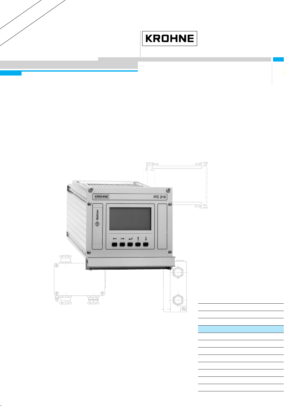
IFC 210 E
IFC 210 E-EEx
Signal converters for
electromagnetic flowmeters
Applicable to
Software Versions
● Operating and check elements
No. 3.18393.01
● Amplifier (ADC)
No. 3.17116.01
● Outputs/inputs (I/O)
No. 3.19005.01
How to use these Instructions
The flowmeters are supplied ready for operation.
The primary head must be installed in the pipeline as described in the installation
instructions inside the packing of the primary head.
– Installation location and connection to power (Section 1) Pages 6-15
– Electrical connection of outputs and inputs (Section 2) Pages 16-22
– Factory settings and start-up (Section 3) Pages 23
Power the flowmeter. THAT’S ALL. The system is operative.
Pull-out
Condensed Instructions
Variable area flowmeters
Vortex flowmeters
Flow controllers
Electromagnetic flowmeters
Ultrasonic flowmeters
Mass flowmeters
Level measuring instruments
Communications technology
Engineering systems & solutions
Switches, counters, displays and recorders
Heat metering
Pressure and temperature
DIN A4: 7.10006.31.00
©
KROHNE 05/2002 US size: 7.10006.71.00
Page 2

&RQWHQWV
Signal converter versions 4
Items included with supply 4
Instrument nameplates 4
System description 5
Product liability and warranty 5
CE / EMC / Standards / Approvals 5
Software history 5
1 Electrical connection: power supply 6
1.1 Location and important installation notes 6
1.2 Power supply - Electrical connection 7
1.3 Electrical connection of separate primary heads 8
1.3.1 General remarks on signal cables A and B and field current line C 8
1.3.2 Stripping (preparation) of signal cables 9
1.3.3 Grounding of primary head 10
1.3.4 Cable lengths (max. distance between signal converter and primary head) 10
1.3.5 Connection diagrams for power supply and primary head 12
1.3.6 EEx-Connection diagrams for power supply and primary head 14
2 Electrical connection of outputs and inputs 16
2.1 Current output I 16
2.2 Pulse output P 17
2.3 Status outputs B1 and B2 18
2.4 Control inputs B1 and B2 19
2.5 Connection diagrams for outputs and inputs 20
3 Start-up 23
3.1 Power-on and measurement 23
3.2 Factory setting 23
3.3 Setting data 24
4 Operation of the signal converter 25
4.1 KROHNE operator control concept 25
4.2 Operating and check elements 26
4.3 Function of keys 27
4.4 Table of settable functions 30
4.5 Error messages in measuring mode 36
4.6 Reset totalizer and cancel error messages 37
4.7 Examples of setting the signal converter 37
5 Description of functions 38
5.1 Full-scale range Q
5.2 Timeconstant (Fct. 1.02) 38
5.3 Low Flow Cutoff (Fct.1.03) 39
5.4 Internal electronic totalizer 39
5.5 Display (Fct. 1.04) 40
5.6 Currentoutput I (Fct. 1.05) 42
5.7 Pulsoutput P (Fct. 1.06) 43
5.8 Statusoutput B1 and / or B2 44
5.9 Controlinput 45
5.10 F/R mode, forward/reverse flow measurement 45
5.11 Set limit values (status output B1 and/or B2) 46
(Fct. 1.01) 38
100%
2
IFC 210 E
05/2002
Page 3

5.12 Automatic range change BA (with status output B1 or B2) and external range change
(with control input B1 or B2) 47
5.13 Language (Fct. 3.01) 48
5.14 Zero check (Fct. 3.03) 48
5.15 Determine Entry Code (Fct. 3.04) 48
5.16 Primary head – Set data (Fct. 3.02) 49
5.17 User-defined unit (Fct. 3.05) 50
5.18 Application (Fct. 3.06) 51
5.19 Hardware (Fct. 3.07) Assignment of terminals B1 + B2 and field current supply 51
5.20 Measuring point identification – Location (Fct. 3.08) 52
5.21 Set communication interface (Fct. 3.09) 52
5.22 Characteristic of outputs 53
6 Special applications 54
6.1 IFC 210 E – EEx for primary heads in hazardous areas 54
6.1.1 General 54
6.1.2 Electrical connection 55
6.1.3 Technical data and terminal assignment 56
6.1.4 Fuse protection of the field power circuit 57
6.2 Interfaces 58
6.2.1 HART- interface 58
6.2.2 KROHNE RS 485 Interface (Option) 60
6.3 Unsteady display and outputs 61
6.4 Pulsating flow 62
6.5 Rapid changes in flowrate 63
6.6 Stable signal outputs when measuring tube empty 64
7 Functional checks 66
7.1 Zero check 66
7.2 Test of measuring range Q 66
7.3 Hardware information and error status, Fct. 2.02 67
7.4 Faults and symptons during start-up and process flow measurement 67
7.5 Checking the primary head 70
7.6 Test of signal converter using GS 8 A simulator (option) 71
8 Service 74
8.1 Illustrations used for service work 74
8.2 Replacement of power supply fuse 75
8.3 Replacement of electronics unit of signal converter 75
8.4 Illustrations of the PCBs 76
9 Order numbers 78
10 Technical data 79
10.1 IFC 210 E signal converter 79
10.2 Full-scale range Q
10.3 Dimensions and weights IFC 210 E-EEx / ZD / ZD-EEx 86
11 Measuring principle 88
12 Block diagram – signal converter IFC 210 E 89
13 EU-Model test certificate ATEX 90
14 Index 92
If you need to return flowmeters for testing or repair to KROHNE 95
85
100%
IFC 210 E 3
05/2002
Page 4
6LJQDOFRQYHUWHUYHUVLRQV
All signal converter versions include local display and control elements.
The operating data are factory-set to your ordered specifications.
IFC 210 E Standard version,
(Standard) with large graphic display and integrated HART® interface
IFC 210 E / RS 485 same as standard version,
(Option) but additionally with RS 485 interface
IFC 210 E / _ / EEx Same as standard version,
(Option) for operation with primary heads installed in hazardous areas
,WHPVLQFOXGHGZLWKVXSSO\
Signal converter in the version as ordered, see above.
These installation and operating instructions for the signal converter,
including pull-out condensed instructions for installation, electrical connection,
start-up and operator control of the signal converter.
signal cable in the version and length as ordered (standard: signal cable A, length 10 m / 30 ft)
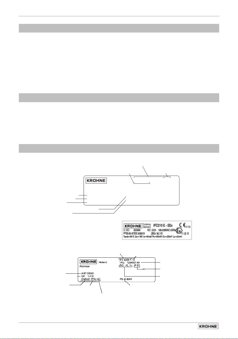
,QVWUXPHQWQDPHSODWHV
signal converter
signal converter IFC 210E-EEx (example)
primary head (example)
Materials for liner and electrodes see Installation Instructions for primary heads
(example)
Altometer
Measuring range
Current output
Tag No.
Primary head constant
Pulse output
Q: 0-150 m
I: 0-20 mA R
Tag: 98-FT-096
Serial No.
Primary head constant
Meter size
DN in mm and
inch equivalent
Teflon®-PFA
Liner
Electrode material
Hastelloy C4
Type designation
Serial No.
Holland
3
/h GK: 2.706
″ 0.5 kOhm P: 1000 p/s
i
Type designation
Flange pressure rating
or flange class
Magnetic field frequency
(here: 1/6 of power
supply frequency)
ALTOFLUX IFC210E /D/ /6
A96 6008
Magnetic field frequency
(here: 1/6 of power supply frequency)
Location Nr.
Protection category
to IEC 529 / EN 60529
Insulation class
of field coils
4
IFC 210 E
05/2002
Page 5
6\VWHPGHVFULSWLRQ
Electromagnetic flowmeters are precision instruments designed for linear flow measurement of
liquid products
The process liquids must be electrically conductive:, ≥ 5 µS/cm
(for cold demineralized water ≥ 20 µS/cm).
The full-scale range Q
flow velocity of 0.3 - 12 m/s or 1 - 40 ft/s (s. Section 10.1.).
can be set as a function of the meter size:
100%
3URGXFWOLDELOLW\DQGZDUUDQW\
The electromagnetic flowmeters are designed solely for measuring the volumetric flowrate of
electrically conductive, liquid process products.
These flowmeters are available for use in hazardous areas.
Special regulations apply in this case, which are given in the special EEx directions.
Responsibility as to suitability and intended use of these electromagnetic flowmeters rests solely
with the operator.
Improper installation and operation of the flowmeters (systems) may lead to loss of warranty.
In addition, the “General conditions of sale” forming the basis of the purchase contract are
applicable.
If flowmeters need to be returned to KROHNE, please note the information given on the last-but-
one page of these Instructions. KROHNE regrets that it cannot repair or check your flowmeter(s)
unless accompanied by the completed form sheet.
&((0&6WDQGDUGV$SSURYDOV
The here described Electromagnetic flowmeters meet the NAMUR Directive NE21,
the protection requirements of
61326-1
in conjunction with
(1997) and A1 (1998), as well as
EN 61010-1
Directive 89/336/EEC
Directives 73/23/EEC
, and bear the
in conjunction with
CE marking.
and
93/68/EEC
EN
6RIWZDUHKLVWRU\
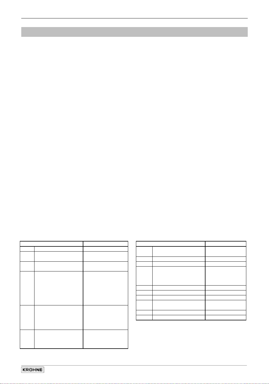
Display & control unit Amplifier (ADC) Inputs and outputs (I/O)
Software Status Software Status Software Status
3.18393.01 current 3.17116.01 current 3.19005.01 current
IMPORTANT!
In respect of EEx versions, pay regard to all directions marked with the symbol,
and also the information given in Sect. 6.1 and 13.
Only the EEx primary head may be installed in the hazardous area.
The signal converter must be installed outside the hazardous area!
IFC 210 E 5
05/2002
Page 6
Sect. 1.1 Part A System installation and start-up
(OHFWULFDOFRQQHFWLRQSRZHUVXSSO\
1
1.1 Location and important installation notes
Electrical connection in accordance with VDE 0100
•
installations with line voltages up to 1000 V” or
•
Do not cross or loop
•
•
•
•
•
•
•
•
separate cable
Use
outputs and inputs.
Protect flowmeters or switchgear cabinets with built-in devices from direct
sunshade if necessary.
installed in switchgear cabinets
When
use fans or heat exchangers. (dust-free air and no aggressive gases)
Do not expose signal converters to intense
distance between primary head and signal converter
Keep
Sect. 1.3.4 for maximum permissible length of signal and field current cables.
Use the supplied KROHNE
optional
Always
ensure
head.
If the GK is not identical, set the signal converter to the GK of the primary head.
Refer also to Section 4.
Dimensions of signal converter,
signal cable B
calibrate
primary constant GK is identical
IMPORTANT!
For EEx versions, also pay regard to all special directions included in Sect. 6.1
and 13.
Only the EEx primary head may be installed in the hazardous area.
The signal converter must be installed outside the hazardous area!
cables
.
entries (see below) for power supply, field current cables, signal cables,
signal cable A
(Type BTS).
primary head and signal converter
refer to Section 10.4.
equivalent others national regulations
, signal converters must be adequately cooled, e.g.
vibration
(Type DS), standard length 10 m (33 ft), or
; refer to instrument nameplate for the primary
”Regulations governing heavy-current
.
together
sunlight
as short as possible. Refer to
. Therefore, when installing,
. Fit a
.
6
IFC 210 E
05/2002
Page 7
Part A System installation and start-up Sect. 1.2
1.2 Power supply - Electrical connection
PLEASE NOTE !
•
Rated values: The flowmeter housings meets the requirements of IP 20 in conformity
with EN 60529.
No protection against water and moisture. If necessary, take appropriate protective
measures.
The selected creepage distances and clearances have been dimensioned in conformity with
VDE 0110 and IEC 664 for contamination category 2. Supply circuits and output circuits are
designed to meet the standards of overvoltage class II.
•
Fuse protection, disconnecting device: fuse protection for the feeding power circuit, and also
a disconnecting device (switch, circuit breaker) for isolating the signal converters must be
provided (see also Sect. 1.3.5).
Power supply 100-230 V AC (Tolerance zone: 85-255 V AC)
•
Note information on instrument nameplate: supply voltage and frequency
•
Connection diagrams for electrical connection between primary head and signal converter:
refer to Section 1.3.5.
Power supply 24 Volt AC / DC (Tolerance zone: AC 20.4 - 26.4 V / DC 18 - 31.2 V)
•
Note information on instrument nameplate: supply voltage and frequency
•
For measurement reasons, connect an FE functional ground conductor.
•
If connected to a functional extra-low voltage source (24 V AC / DC, 48 V AC), provide for
protective separation (PELV) in conformity with e.g. VDE 0100 / VDE 0106 or
IEC 364 / IEC 536, or equivalent national regulations.
•
Connection diagrams for power supply and electrical connection between primary head and
signal converter: refer to Section 1.3.5.
IMPORTANT!
For EEx versions, also pay regard to all special directions included in Sect. 6.1
and 13.
Only the EEx primary head may be installed in the hazardous area.
The signal converter must be installed outside the hazardous area!
IFC 210 E 7
05/2002
Page 8
Sect. 1.3.1 Part A System installation and start-up
1.3 Electrical connection of separate primary heads
1.3.1 General remarks on signal cables A and B and field current line C
Proper operation of the equipment is ensured when KROHNE signal cables A and B are used with
foil screen and magnetic shield.
•
Signal cables must be firmly installed.
•
Shields are connected via stranded drain wires.
•
Underwater or underground routing is possible.
•
Insulating material flame-retardant to IEC 332.1 / VDE 0742.
•
Low-halogen, unplasticized signal cables which remain flexible at low temperatures.
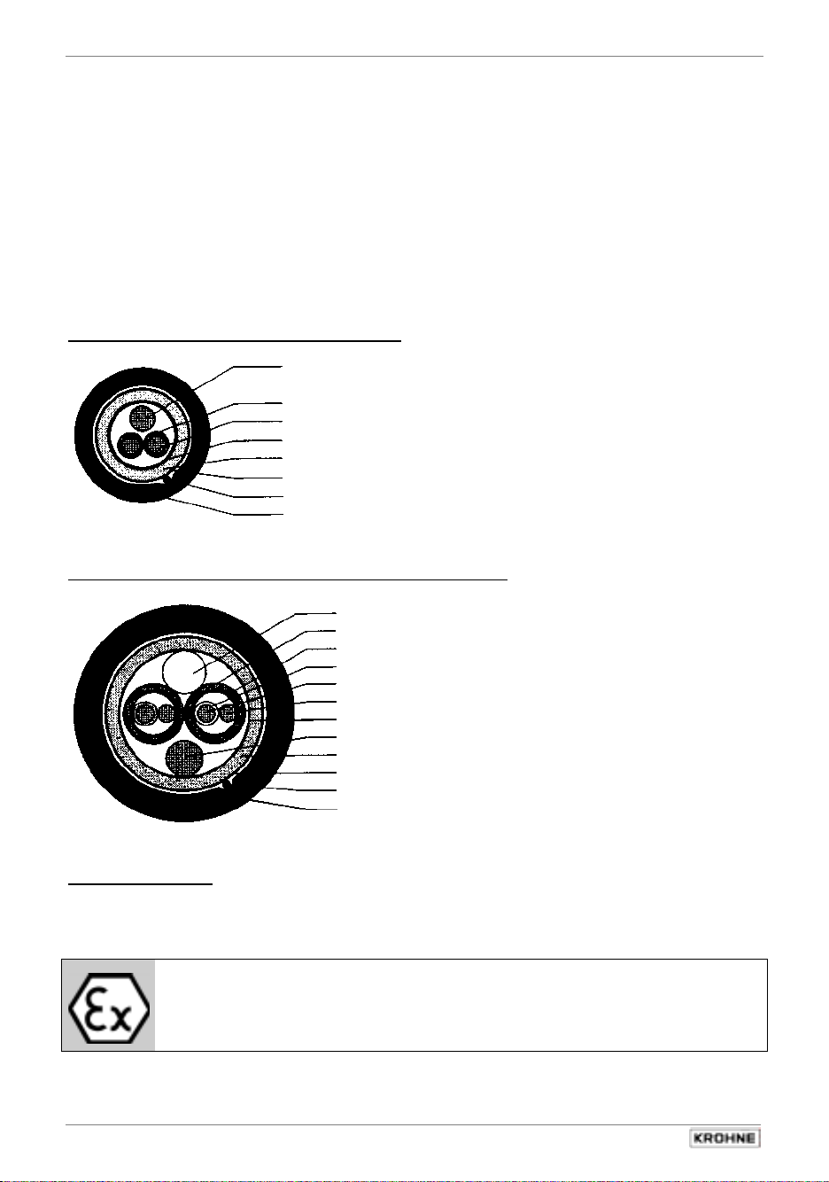
Signal cable A (type DS) with double shielding
1 Stranded drain wire, 1st shield, 1.5 mm
2 Insulation
3 Stranded wire 0.5 mm2 (3.1 red/3.2 white)
4 Special foil, 1st shield
5 Insulation
6 Mu-metal foil, 2nd shield
7 Stranded drain wire, 2nd shield, 0.5 mm2
8 Outer sheath
Signal cable B (type BTS) with triple shielding (bootstrap line)
1 Dummy glider wire
2 Insulation (2.1 red/2.2 white)
3 Special foil, 1st shield (3.1/3.2)
4 Insulation (4.1/4.2)
5 Stranded wire 0.5 mm
6 Stranded drain wire, 1st shield, 0.5 mm2 (6.1 / 6.2)
7 Special foil, 2nd shield
8 Stranded drain wire, 2nd shield, 1,5 mm2
9 Insulation
10 Mu-metal foil, 3rd shield
11 Stranded drain wire, 3rd shield,, 0,5 mm2
12 Outer sheath
Field current line C
Line 2 × 0,75 mm2, 2 × 1,5 mm2 or 4 × 1,5 mm2Cu, single shielding
(Cu = copper cross section)
The cross section depends on the required cable length, see table in Section 1.3.4.
IMPORTANT!
For EEx versions, also pay regard to all special directions included in Sect. 6.1
and 13.
Only the EEx primary head may be installed in the hazardous area.
The signal converter must be installed outside the hazardous area!
2
2
(5.1 red/5.2 white)
8
IFC 210 E
05/2002
Page 9
Part A System installation and start-up Sect. 1.3.2
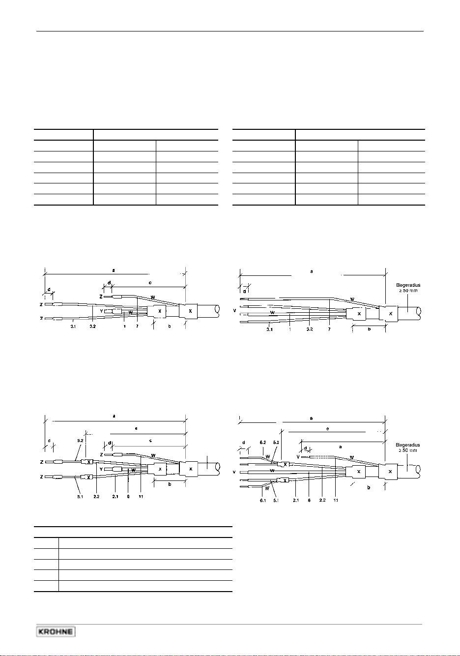
1.3.2 Stripping (preparation) of signal cables
Please note: The numbers in the drawings designate the stranded drain wires of signalling cables
A and B, see sectional drawings in Sect. 1.3.1.
primary head Converter
Length primary head Length Converter
mm inch mm inch
a 90 3.60 a 40 2.80
b 8 0.30 b 10 0.30
c 25 1.00
d 8 0.30 d 5 0.30
e 70 2.80 e 20 2.00
Signal cable A (type DS),
double shielding
for primary head
Signal cable A (type DS),
double shielding
for IFC 210 E Converter
Signal cable A
bending radius
bending radius
≥
50 mm (≥ 2”)
≥
50 mm (≥ 2”)
Signal cable B (type BTS),
with triple shielding (bootstrap)
for primary head
Signal cable B
bending radius
bending radius
≥
50 mm (≥ 2”)
≥
50 mm (≥ 2”)
Customer-supplied materials
V Tin-coat all stranded drain wire ends!
W Insulation tubing (PVC), Ø 2.0-2.5 mm (Ø 1”)
X Heat-shrinkable tubing or cable sleeve
Y Wire end sleeve to DIN 41 228: E 1.5-8
Z Wire end sleeve to DIN 41 228: E 0.5-8
Signal cable B (type BTS),
with triple shielding (bootstrap)
for IFC 210 E Converter
IFC 210 E 9
05/2002
Page 10
Sect. 1.3.3 Part A System installation and start-up
1.3.3 Grounding of primary head
•
All flowmeters must be grounded.
•
The grounding conductor should not transmit any interference voltages.
•
Do not ground any other electrical device together with this conductor.
•
The primary head is connected to ground by means of an FE functional ground conductor.
•
Special information on grounding various primary heads is contained in the separate
installation instructions for primary heads.
•
These instructions also contain detailed descriptions on how to use grounding rings and how
to install primary heads in metal or plastic pipes or internally coated pipelines.
IMPORTANT!
For EEx versions, also pay regard to all special directions included in Sect. 6.1
and 13.
Only the EEx primary head may be installed in the hazardous area.
The signal converter must be installed outside the hazardous area!
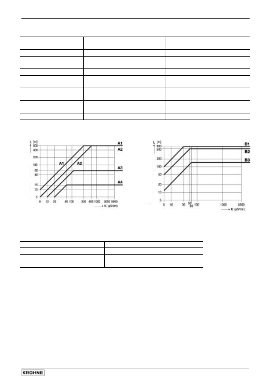
1.3.4 Cable lengths (max. distance between signal converter and primary head)
Abbreviations and explanatory notes
used in the following tables, diagrams and connection diagrams
A Signal cable A (type DS), with double shielding, see diagram A for max. length
B Signal cable B (type BTS) with triple shielding, max. length see diagram B
C Field current cable min. cross-section (AF) and max. length, see Table
D High-temperature silicone cable, 3 × 1.5 mm
2
(14 AWG) Cu, (with single shielding,
max. length 5 m (16 ft)
E High-temperature silicone cable, 2 × 1.5 mm
2
(14 AWG) Cu, max. length 5 m (16 ft)
Cross section of field current line C in Cu, see table
A
F
L Cable length
Electrical conductivity of the process liquid
κ
ZD Intermediate connection box required in connection with cables D and E for primary heads
ALTOFLUX IFS 4000 F, PROFIFLUX IFS 5000 F and VARIFLUX IFS 6000 F in cases
where process temperatures exceed 150 °C (302 °F)
10
IFC 210 E
05/2002
Page 11
Part A System installation and start-up Sect. 1.3.4
Recommended length of signal cable A (Type DS) and B (Type BTS)
Primary head Meter size Signal cable
DN mm inch A B
AQUAFLUX F 10 - 1600
ECOFLUX IFS 1000 F 10
25 - ALTOFLUX IFS 2000 F 150 - 250 6 - 10 A1 B1
ALTOFLUX IFS 4000 F 10
200 - PROFIFLUX IFS 5000 F 2.5
25 - VARIFLUX IFS 6000 F 2.5 - 15
25 - 80 1 - 3 A2 B2
ALTOFLUX M 900 10 - 300
15
150
150
1600
15
100
3
/8 - 64 A1 B1
3
/
- - ½
8
1
3
/
8
8
1
/
10
1
1
/10 - ½ A4 B3
3
/8 - 12 A1 B1
6
- - 6
64
- - ½
4
A4
A3
A2
A1
A4
A2
B3
B2
B2
B1
B3
B2
Diagram A Diagram B
Field current cable C
Length L Cross section AF (Cu), minimum
0 – 150 m 5 – 500 ft 2 x 0.75 mm2 / 2 × 18 AWG
150 – 300 m 500 – 1000 ft 2 x 1.50 mm2 / 2 × 14 AWG
300 – 600 m 1000 – 1900 ft 4 x 1.50 mm2 / 2 × 12 AWG
IFC 210 E 11
05/2002
Page 12
Sect. 1.3.5 Part A System installation and start-up
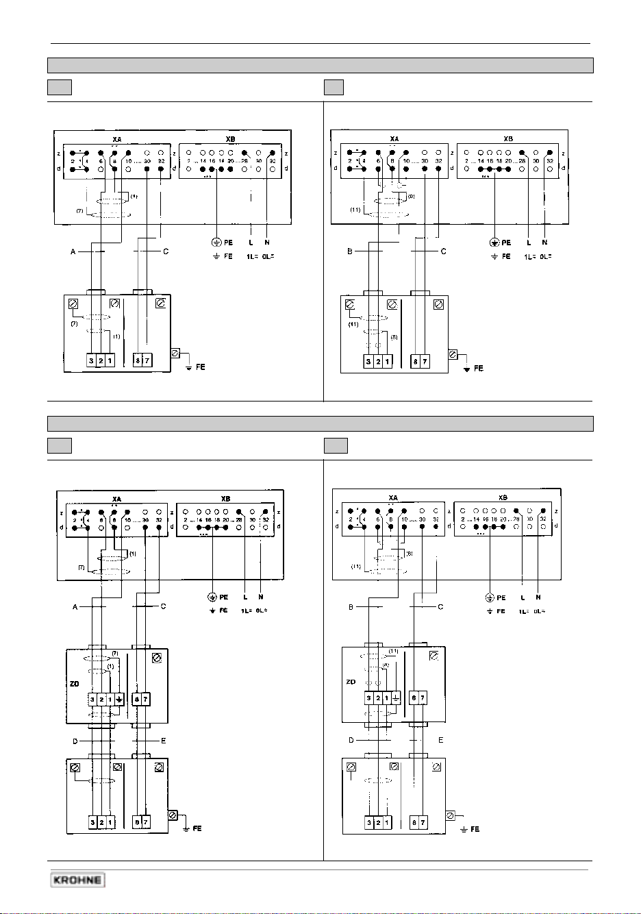
1.3.5 Connection diagrams for power supply and primary head
PLEASE NOTE: Undocumented contacts/terminals to remain unwired.
The figures in brackets indicate the stranded drain wires for the shields
(see cross-sectional drawing of signal cable in Section 1.3.1).
•
Electrical connection to VDE 0100 "Regulations governing heavy-current installations with
line voltages up to 1000 V" or equivalent national regulations.
•
24 V AC / DC power supply:
Functional extra-low voltage with protective separation in
conformity with VDE 0100, Part 410 or equivalent national
regulations (IFC 020 E: 24 V DC in preparation).
•
Fuse protection of the feed line circuit with I
≤ 16 A is required. Also, a disconnecting
RAT
device (switch/circuit breaker) must be provided in the vicinity of the solidly connected signal
converters or device groups, refer to EN 61 010. This disconnecting device must be easy to
reach and also identifiable as such.
Contacts 2d, 2z, 4d, 4z of
*
XA must be electrically
connected.
Connection to 8d and/or
**
8z of XA.
Contacts d2 to d32 of XB
***
are of leading type, for
connection of PE (safety
conductor) or FE
(functional ground).
At least 4 contacts with
adequate cross-section to
be electrically connected.
Important:
Electrical connection of EEx primary heads and EEx signal converters
To be carried out as described in Sect. 1.3.6.
12
IFC 210 E
05/2002
Page 13
Part A System installation and start-up Sect. 1.3.5
I Signal cable A (type DS) II Signal cable B (type BTS)
IFC 210 E IFC 210 E
Process temperature < 150°C (302°F)
Primary head Primary head
III Signal cable A (type DS) IV Signal cable B (type BTS)
IFC 210 E IFC 210 E
Process temperature > 150°C (302°F)
Primary head Primary head
IFC 210 E 13
05/2002
Page 14
Sect. 1.3.6 Part A System installation and start-up
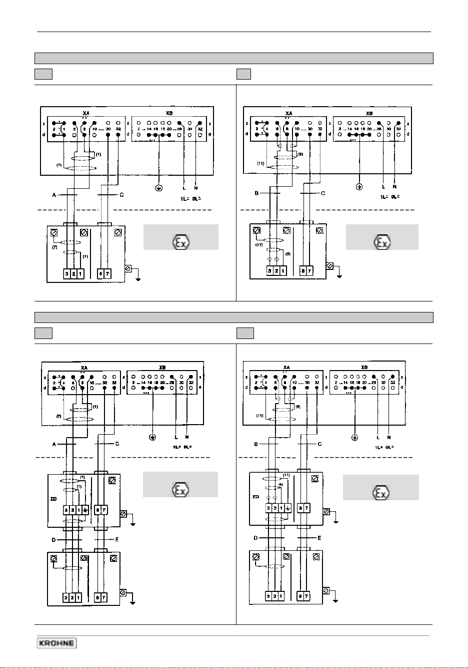
1.3.6 EEx-Connection diagrams for power supply and primary head
Connection diagrams
PLEASE NOTE: Undocumented contacts/terminals to remain unwired.
The figures in brackets indicate the stranded drain wires for the shields
(see cross-sectional drawing of signal cable in Section 1.3.1).
•
Electrical connection to VDE 0100 "Regulations governing heavy-current installations with
line voltages up to 1000 V" or equivalent national regulations.
•
24 V AC / DC power supply:
Functional extra-low voltage with protective separation in
conformity with VDE 0100, Part 410 or equivalent national
regulations (IFC 020 E: 24 V DC in preparation).
•
Fuse protection of the feed line circuit with I
≤ 16 A is required. Also, a disconnecting
RAT
device (switch/circuit breaker) must be provided in the vicinity of the solidly connected signal
converters or device groups, refer to EN 61 010. This disconnecting device must be easy to
reach and also identifiable as such.
Contacts 2d, 2z, 4d, 4z of
*
XA must be electrically
connected.
Connection to 8d and/or
**
8z of XA.
Contacts d2 to d32 of XB
***
are of leading type, for
connection of PE (safety
conductor) or FE
(functional ground).
At least 4 contacts with
adequate cross-section to
be electrically connected.
Important:
In respect of EEx versions, pay regard to all directions marked with the symbol,
and also the information given in Sect. 6.1 and 13.
Only the EEx primary head may be installed in the hazardous area.
The signal converter must be installed outside the hazardous area!
14
IFC 210 E
05/2002
Page 15
Part A System installation and start-up Sect. 1.3.6
I Signal cable A (type DS) II Signal cable B (type BTS)
IFC 210 E-EEx IFC 210 E-EEx
Process temperature < 150°C (302°F)
PE/PA
PE/PA
Hazardous area
PA
Primary head Primary head
Hazardous area
PA
III Signal cable A (type DS) IV Signal cable B (type BTS)
Process temperature > 150°C (302°F)
IFC 210 E-EEx IFC 210 E-EEx
PE/PA
Hazardous area
PE/PA
Hazardous area
PA
PA
Primary head Primary head
IFC 210 E 15
05/2002
PA
PA
Page 16
Sect. 2.1 Part A System installation and start-up
(OHFWULFDOFRQQHFWLRQRIRXWSXWVDQGLQSXWV
2
Important:
In respect of EEx versions, pay regard to all directions marked with the symbol,
and also the information given in Sect. 6.1 and 13.
Only the EEx primary head may be installed in the hazardous area.
The signal converter must be installed outside the hazardous area!
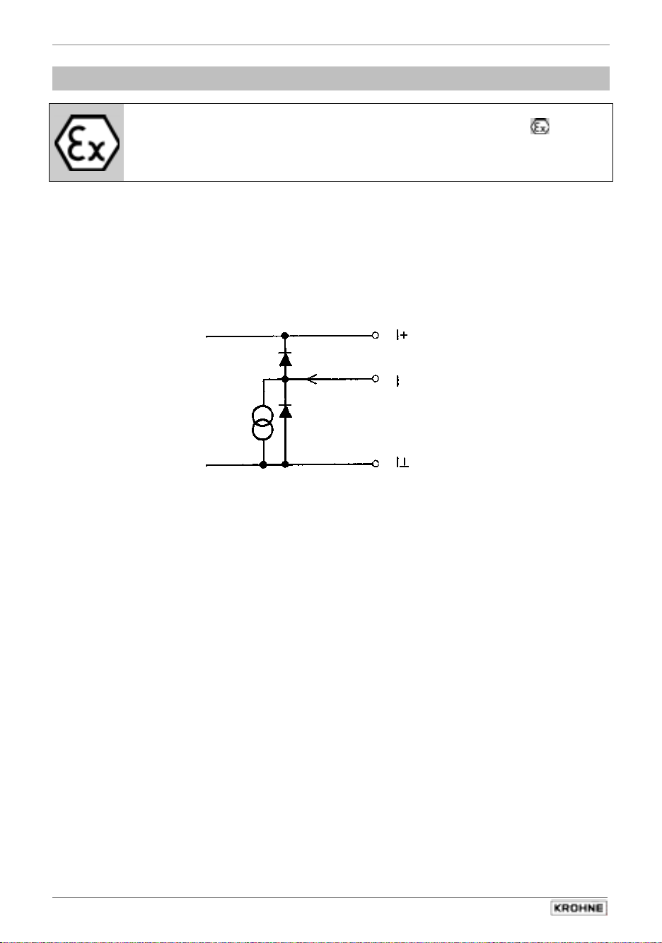
2.1 Current output I
•
The current output is galvanically isolated from all input and output circuits.
•
Setting data and functions can note down in Section 3.3.
Please also refer to Sect. 3.2 Factory settings.
•
Typical current
output
•
All operating data and functions can be set, see Sect. 4 and 5.6, Fct. 1.05 for operator control
•
The current output can also be used as an internal voltage source for the binary outputs and
inputs.
•
U
= 22-25 V DC
int
I = 23 mA when operated without receiver instruments at the current
output
I = 3 mA when operated with receiver instruments at the current output
•
Connection diagrams, see Sect. 2.5: diagrams
c d e g i k l
approx. 22-25 V DC positive
voltage of current output
current sink
chassis ground, current output
16
IFC 210 E
05/2002
Page 17
Part A System installation and start-up Sect. 2.2
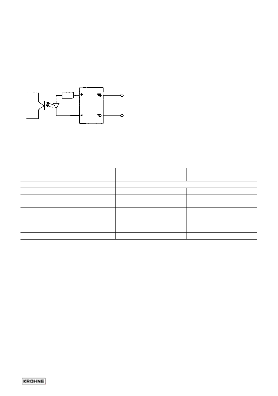
2.2 Pulse output P
•
The pulse output is galvanically isolated from the current output and all input circuits.
•
Setting data and functions can note down in Section 3.3.
Please also refer to Sect. 3.2 Factory settings.
•
Typical pulse output P
•
All operating data and functions can be set, see Sect. 4 and 5.7, Fct. 1.06 for operator control
•
The pulse output can be operated in the active or passive mode.
•
Active mode:
•
Passive mode:
Please note:
A fixed pulse width (0.01 – 1s) must be set for operation with EMC
•
Digital pulse division, interpulse period is non-uniform. Therefore, if frequency meters or
•
cycle counters are connected, allow for minimum counting interval:
•
gate time, counter ≤
•
Connection diagrams, see Sect. 2.5: diagrams
The current output is the internal voltage source,
connection of electronic totalizers (EC)
External DC or AC voltage source required,
connection of electronic (EC) or electromechanical (EMC) totalizers
totalizer. Only then is an optocoupler active for higher output currents.
1000
[Hz]
P
100%
e
f k l
P pulse output
P pulse output
IFC 210 E 17
05/2002
Page 18
Sect. 2.3 Part A System installation and start-up
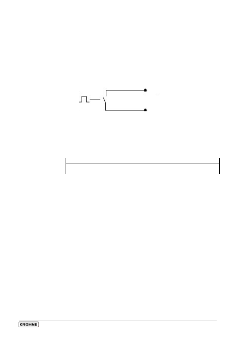
2.3 Status outputs B1 and B2
•
The status outputs are galvanically isolated from the current output and all input circuits.
•
Setting data and functions can note down in Section 3.3.
Please also refer to Sect. 3.2 Factory settings.
•
Typical status outputs B1 and/or B2
B1/B2 status outputs B1/B2
B⊥ chassis ground,
binary outputs and inputs
•
All operating data and functions can be set,
see Sect. 4 and 5.9, Fct 1.07 and/or 1.08 for operator control
The status outputs can be operated in the active or passive mode.
Active mode: The current output is the internal voltage source.
Passive mode: External DC or AC voltage source required.
Characteristics of the status outputs Switch open Switch closed
OFF (switched off) no function
ON (e.g. operation indicator) Power supply OFF Power supply ON
SIGN I (F/R mode) Forward flow Reverse flow
SIGN P (F/R mode) Forward flow Reverse flow
TRIP POINT (limit switch) inactive active
AUTO RANGE (automatic range
change)
OVERFLOW I (I overranged) current output OK current output overranged
OVERFLOW. P (P overranged) pulse output OK pulse output overranged
SMU I (low-flow cutoff active) Inactive active
SMU P (low-flow cutoff active) Inactive active
Inverse B1 (switches B2 inversely to B1) B2 open, B1 closed B2 closed, B1 open
ALL. ERROR (all errors) errors no error
FATAL.ERROR (fatal errors only) errors no error
EMPTY PIPE (option) when measuring tube is empty when measuring tube is full
high range low range
•
Connection diagrams, see Sect. 2.5: diagrams
g
h k l
18
IFC 210 E
05/2002
Page 19
Part A System installation and start-up Sect. 2.4
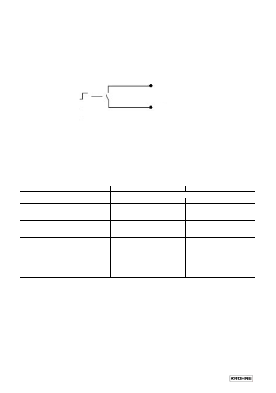
2.4 Control inputs B1 and B2
•
The control inputs are galvanically isolated from the current output and all input circuits.
•
Setting data and functions can note down in Section 3.3.
Please also refer to Sect. 3.2 Factory settings.
•
Typical current inputs B1 and B2
B1/B2
B⊥
•
All operating data and functions can be set,
see Sect. 4 and 5.10, Fct 1.07 and/or 1.08 for operator control
•
The control inputs must be operated in the passive mode.
Function of the control inputs inactive active
no voltage voltage present
Off No functions
External range High range Low range
Hold measured values Measured values follow the Hold measured values
measurement
Measured values at zero Measured values follow the
measurement
Measured values set to
“zero“
Reset totalizer inactive Reset totalizer
Delete errors inactive Delete error messages
Connection diagram, see Sect. 2.5: diagram
i
j
IFC 210 E 19
05/2002
Page 20
Sect. 2.5 Part A System installation and start-up
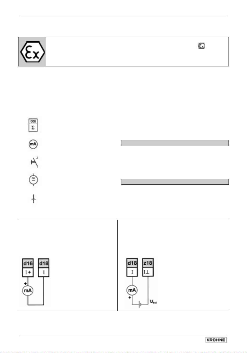
2.5 Connection diagrams for outputs and inputs
I
P
B1, B2
Current output I
c
= 0/4-20 mA
U
< 800 Ω
R
L
Important:
In respect of EEx versions, pay regard to all directions marked with the symbol,
and also the information given in Sect. 6.1 and 13.
Only the EEx primary head may be installed in the hazardous area.
The signal converter must be installed outside the hazardous area!
Current output (included HART
Pulse output
Status output (S) and / or
Control input (C)
Totalizer
- electromechanical (EMC)
- electronic (EC)
milliammeter
0-20 mA or 4-20 mA and other
Key, N/O contact
External voltage source (U
DC or AC voltage,
connection polarity arbitrary
DC voltage,
external power source (U
®
Please note ! Unwired contacts may not have
)
any conductive connection with other electrically
conducting parts.
Electrical connection to socket connector XC
Wiring diagrams c to l of outputs and inputs.
Interface operation with HART® or
RS 485 (Option) see Sect. 6.2.1 and 6.2.2.
Power for operation (activation) of outputs and
inputs supplied by the current output.
),
ext
Active mode
External power source required for operation
(activation) of outputs and inputs.
),
ext
Passive mode
note connection polarity
aktiv
Current output I
d
15-22 V DC 22-32 V DC
U
ext
R
0-500 Ω 0-800
L
= 0/4-20 mA
I
passiv
Ω
20
IFC 210 E
05/2002
Page 21
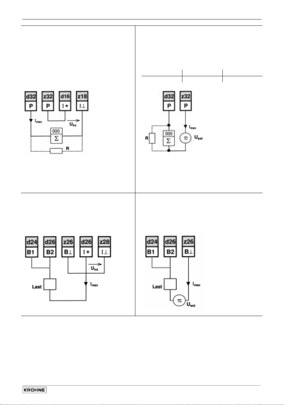
Part A System installation and start-up Sect. 2.5
Pulsoutput P
e
for electronic totalizer (EC)
= 22-25 V DC from current output
U
int
≤ 3 mA operation with current output I
I
max
≤ 23 mA operation
I
max
activ
without
current output I
R = 10 kΩ, prevents incorrect counts
when pulse output in open circuit
Where frequencies are > 100 Hz, use shielded
cables (RFD)
Statusoutput S
g
(connection to B2 and/or B1)
= 22-25 V DC from current output
U
int
≤ 3 mA operation with current output I
I
max
≤ 23 mA operation without current output I
I
max
activ
Pulsoutput P
f
for electronic totalizer (EC) or
passiv
electromechanical totalizer (EMC)
EMC:
EC:
Pulses
R (load)
U
I
max
U
≤ 32 V DC /
ext
≤ 150 mA
≤ 32 V DC
ext
≤ 1 kHz
1-10 kΩ 1-3 kΩ
≤ 24 V AC
f ≤ 50 Hz
≤ 20 mA
I
max
< 10 kHz
R = load impedance with EC totalizer operation; for
value refer to table above
Where frequencies are > 100 Hz, use shielded cables
(RFD)
Statusoutput S
h
(connection to B2 and/or B1)
U
≤ 32 V DC / ≤ 24 V DC
ext
I
max
≤ 150 mA
passiv
IFC 210 E 21
05/2002
Page 22
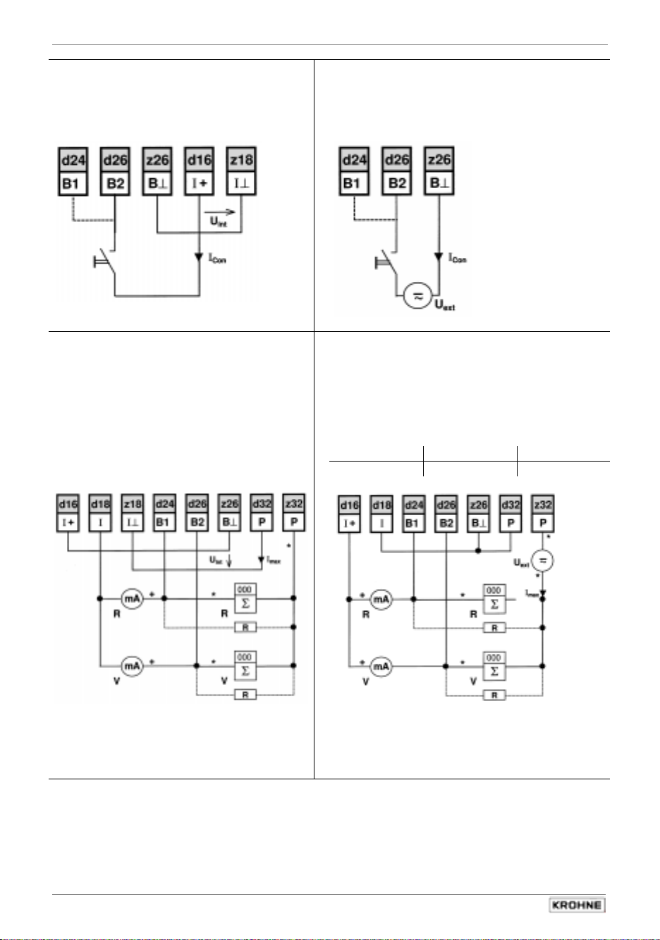
Sect. 2.5 Part A System installation and start-up
Control input C
i
(connection to B2 and/or B1)
= 22-25 V DC from current output
U
int
≤ 4 mA (max. contact rating)
I
con
active
Control input C
j
(connection to B2 and/or B1)
U
≤ 32 V DC / ≤ 24 V AC
ext
I
con
≤ 6 mA (max. contact rating)
passive
F/R measurement (F=forward) (R=reverse)
k
Current output I
pulse output P
without external changeover relay
= 22-25 V DC from current output
U
int
≤ 3 mA operation
I
max
≤ 23 mA operation
I
max
and/or
active
(for EC)
aktive
current output I
with
without
current output I
F/R measurement (F=forward) (R=reverse)
l
Current output I
pulse output P
without external changeover relay
EMC:
EC:
Pulses
R (load)
≤ 32 V DC /
U
ext
≤ 150 mA
I
max
≤ 32 V DC
U
ext
and/or
passive
(for EC or EMC)
passive
≤ 24 V AC
f ≤ 50 Hz
≤ 20 mA
I
max
≤ 1 kHz
< 10 kHz
1-10 kΩ 1-3 kΩ
= 10 kΩ, prevents incorrect counts
R
when pulse output in open circuit
Where frequencies are > 100 Hz, use shielded
*
cables (RFD)
R = load impedance with EC totalizer operation; for
value refer to table above
Where frequencies are > 100 Hz, use shielded
*
cables (RFD)
22
IFC 210 E
05/2002
Page 23
Part A System installation and start-up Sect. 3.1
6WDUWXS
3
3.1 Power-on and measurement
•
Before powering the system, please check that it has been correctly installed according to
Sect. 1 and 2.
•
The flowmeter is delivered ready for operational use. All operating data have been factory set
in accordance with your specifications.
Please refer to Sect. 3.2 “factory settings”.
•
Power the unit, and the flowmeter will immediately start process flow measurement.
•
Refer to Sect. 4 and 5 for operator control.
3.2 Factory setting
All operating data are factory set according to your order specifications.
If you have not made any particular specifications at the time of ordering, the instruments will be
delivered with the standard parameters and functions listed in the Table below.
To facilitate easy and rapid initial start-up, current output and pulse output are set to process flow
measurement in “2 flow directions”, so that the current flowrate is displayed and the volumetric
flow counted independent of the flow direction. The measured values may possibly be shown with
a “ – ” sign.
This factory setting for the current and pulse outputs may possibly lead to measuring errors,
particularly in the case of volume flow counting:
For example, if pumps are switched off and a “backflow” occurs which is not within the range of
the low-flow cutoff (SMU), or if separate displays and counts are required for both flow directions.
To avoid faulty measurements, therefore, it may be necessary to change the factory setting of
some or all of the following functions:
– low-flow cutoff SMU, Fct. 1.03, Sect. 5.3
– display, Fct. 1.04, Sect. 5.4
– current output I, Fct. 1.05, Sect. 5.6
– pulse output P, Fct. 1.06, Sect. 5.7
Operation see
Standard factory settings
Function Setting Function Setting
1.01 Full-scale range Q
1.02 Time constant 3 s, for I, B1, B2 directions
and display 1.08 Control input B2 off
1.03 Low-flow ON: 1% 3.01 Language for display only English
cutoff SMU OFF: 2% 3.02 Flowmeter
1.04 Display diameter see nameplate
flow rate m3/hr or US Gal /mi n flow direction (see arrow
totalizer(s) m3 or US Gal on primary head) } + direction
Messages no 3.04 Entry code no
Trend Mittelwert 3.05 User unit Liter/hr or USMGal/day
Updating 1 sec. 3.06 Application: Flow steady
Scaling auto 3.07 Hardware: Terminal B1 Statusoutput
1.05 Current output I Terminal B2 Control input
function 2 directions 3.08 Location ALTOMETER
Range I 4-20 mA 3.09 Communication off
I Max 22 mA
I Error 22 mA
1.06 Pulse output P
function 2 directions
pulse width 50 ms
pulse value 1 pulse/s
Section 4 and 5
1.07 Status output B1 flow
100%
.
IFC 210 E 23
05/2002
Page 24
Sect. 3.3 Part B IFC 210 Signal converter
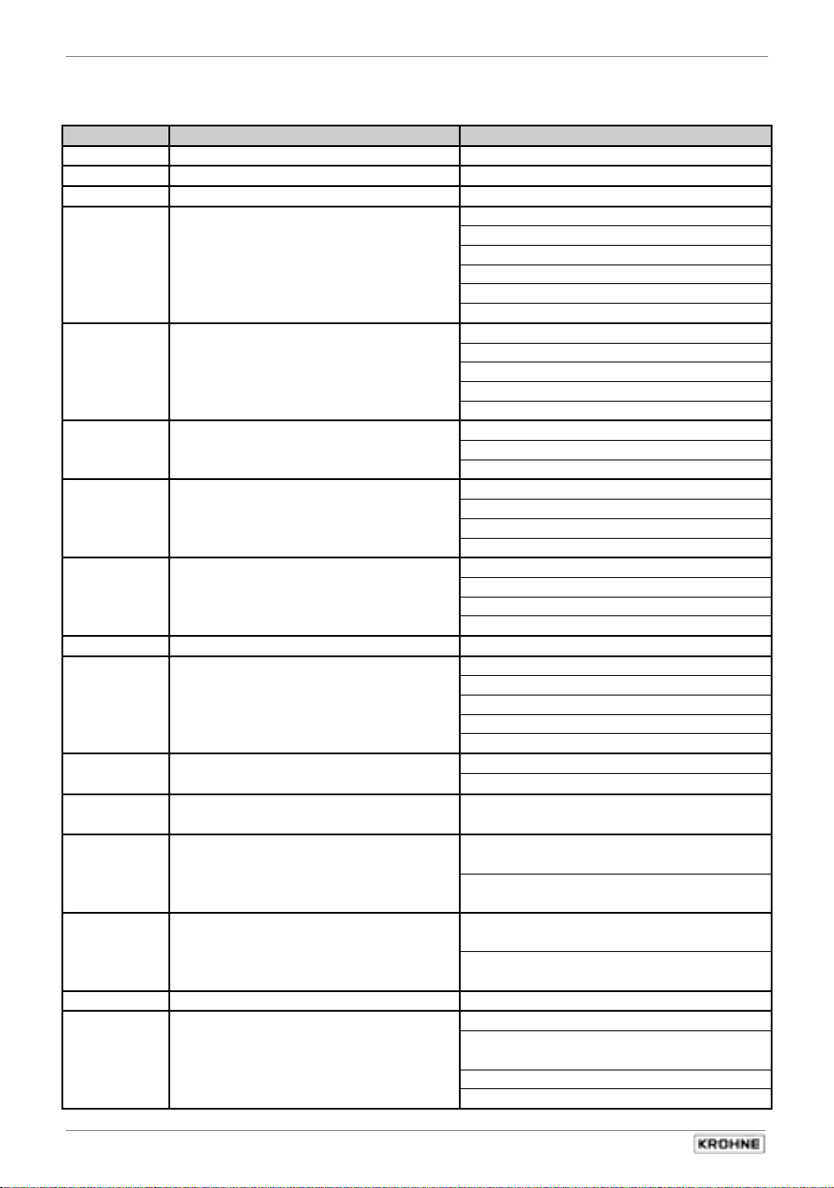
3.3 Setting data
Here you can note down the settings of the signal converter !
Fct. No. Function Settings
1.01 Full-scale range
1.02 Time constant
1.03 Low-flow cut-off ON: OFF:
1.04 Display
1.05 Current output I
1.06 Pulse output P
1.07 Status output B1 or
Control input B1
(for setting see below, Fct. No. 3.07,
terminal B1)
1.08 Status output B2 or
Control input B2
(for setting see below, Fct. No. 3.07,
terminal B2)
3.01 Language
3.02 Primary head
3.04 Entry code required ?
3.05 User-defined unit
Flow
Totalizer
Messages
Trend
Updating
Scaling
Function
Reverse Range
Range I
I Max
I Error
Function
Pulswidth
Pulsvalue
Diameter
GK Value
Field Frequency
Line Frequency
Flow Direction
no
yes
→ → → ↵ ↵ ↵ ↑ ↑ ↑
3.06 Application
3.07 Hardware-setting
3.08 Measuring point
3.09 Communication
24
IFC 210 E
Flow is
Empty Pipe
Terminal B1 is
Terminal B2 is
off
HART or
KROHNE RS 485
Address:
Baud rate:
steady
pulsating
no
yes
Status output
Control input
Status output
Control input
05/2002
Page 25
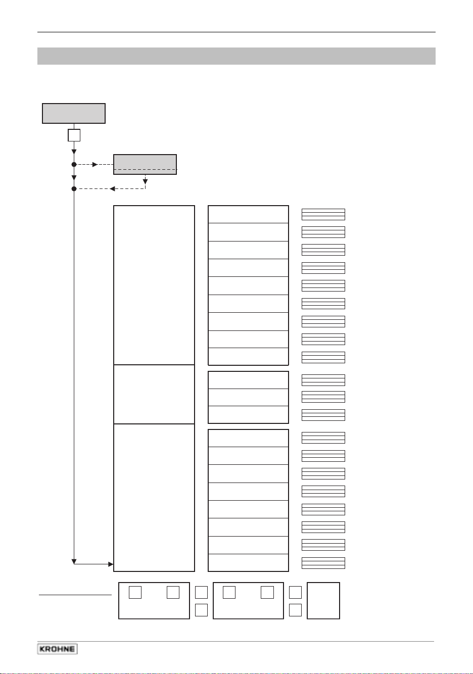
Part B IFC 210 Signal converter Sect. 4.1
1 3 6. 4 9
m 3 /hr
Measuring mode
→
Code 1
Menu column
Function column
Data column
3.00 Installation
2.00 Test
1.00 Operation
3.06 Application
3.07 Hardware
3.08 Location
3.09 Communication
3.05 User Units
3.04 Entrycode
3.03 Zero Point
3.02 Flow Meter
2.02 Hardwareinfo
2.01 Test Q
1.07 Out-/Input B1
1.08 Out-/Input B2
1.06 Pulsoutput P
1.05 Currentoutput I
1.04 Display
1.03 Low Flow Cutoff
1.02Timeconstant
1.01 Full Scale
Direction of movement
↓
↑
↑
↓
→
↵
↵
→
see
Sect.
4.4
When this display appears, press following keys:
→ → → ↵ ↵ ↵ ↑ ↑ ↑
3.01
Language
2.03 Test Display
2SHUDWLRQRIWKHVLJQDOFRQYHUWHU
4
4.1 KROHNE operator control concept
05/2002
IFC 210 E 25
Page 26
Sect. 4.2 Part B IFC 210 Signal converter
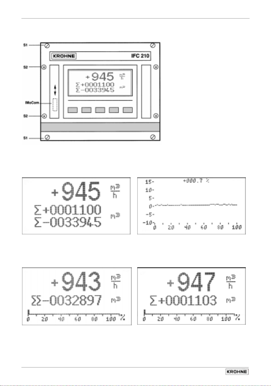
4.2 Operating and check elements
Graphic LCD
c
5 keys for operator control
d
ImoCom interface
e
c
e
Flowrate in m
+ and – totalizer in m3 Graphic display (Trend)
3
/hr
d
Flowrate in m
sum totalizer in m3 (+ and – totalizer) + totalizer in m3
26
IFC 210 E
3
/hr Flowrate in m3/hr
05/2002
Page 27

Part B IFC 210 Signal converter Sect. 4.3
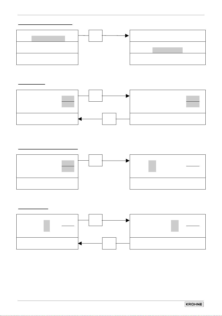
4.3 Function of keys
The cursor has a grey background in the following descriptions.
To start operator control
– 298
Σ
+00000.00
m3 1.00 Operation
Σ
–05632.01
PLEASE NOTE: When “yes” is set under Fct. 3.04 Entry Code,
To select a function
1.06 Pulsoutput P 1.06 Pulsoutput P
1.05 Currentoutput I
1.04 Display 1.04 Display
1.03 Low Flow Cutoff 1.03 Low Flow Cutoff
1.02 Timeconstant 1.02 Timeconstant
1.01 Full Scale
To select a subfunction
1.06 Pulsoutput P Function:
1.05 Currentoutput I
1.04 Display Range I:
1.03 Low Flow Cutoff 00 – 20 mA
1.02 Timeconstant I Max:
1.01 Full Scale
To alter texts
1 Direction
Function: Function:
Range I: Range I:
00 – 20 mA 00 – 20 mA
I Max: I Max:
20.5 mA
3
m
hr
„Code“ appears in the display after pressing the → key.
The 9-keystroke Entry Code 1 must now be entered:
→ → → ↵ ↵ ↵ ↑ ↑ ↑
→
(each keystroke acknowledged by “*”).
Increase number
↑
1.05 Currentoutput I I
↓
Decrease number
→
1 Direction
select next text
↑
2 Directions
↓
select preceding text
3.00 Installation
2.00 Test
1.01 Full Scale
20.5 mA
20.5 mA
IFC 210 E 27
05/2002
Page 28
Sect. 4.3 Part B IFC 210 Signal converter
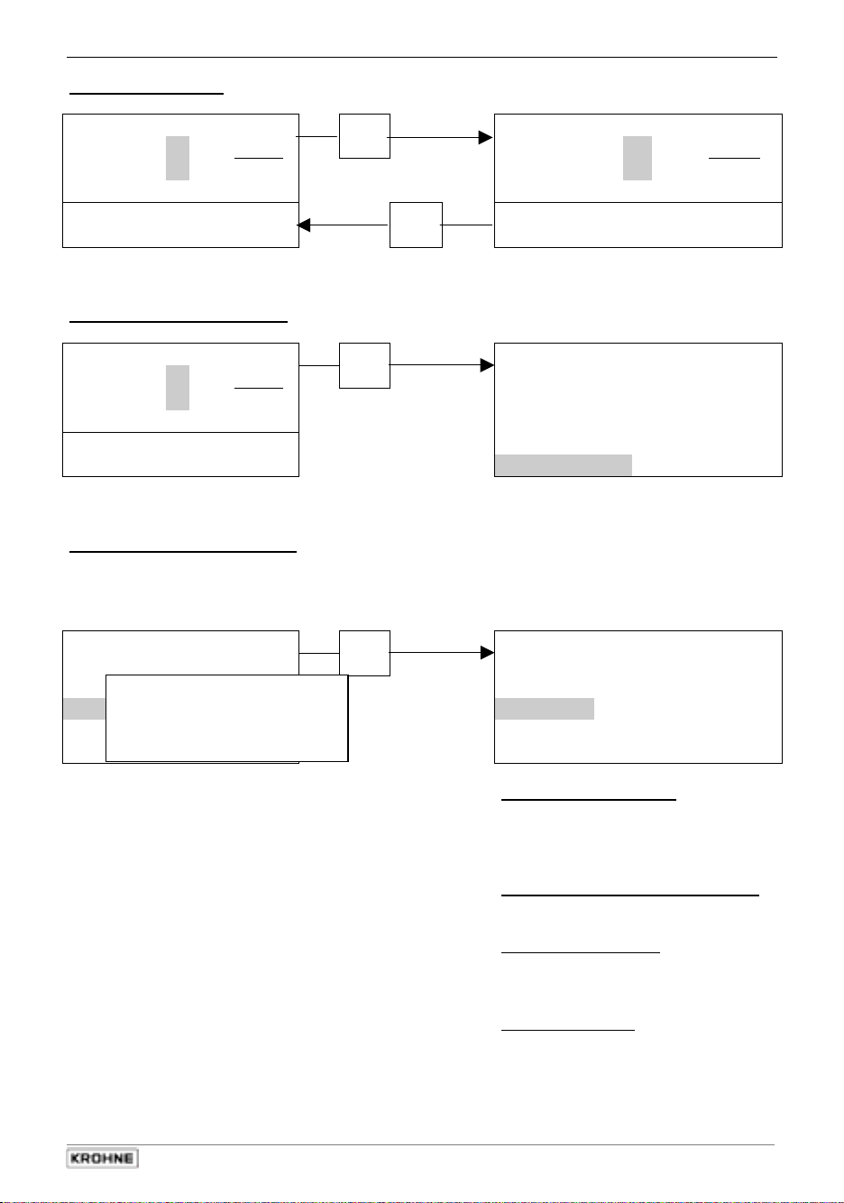
To select next subfunction
Function: Function:
2 Directions
Range I: Range I:
00 – 20 mA 00 – 20 mA
I Max: I Max:
20.5 mA
To alter units
m3
To transfer to number setting
m3
To shift cursor
m
Full Scale Full Scale
2 8 2 7 4
[00849 – 33929] [0235.7 – 9424.7]
Full Scale Full Scale
2 8 2 7
[00849 – 33929] [00849 – 33929]
Full Scale Full Scale
2 8 2 7
[00849 – 33929] [00849 – 33929]
hr
4
hr
3
4
hr
↵
2 Directions
select next unit
↑
Liter
↓
select preceding unit
→
m3
shift to right
→
m3
←
shift to left
20.5 mA
7 8 5 3 . 9
the numerical value is
converted automatically
2 8 2 7
2 8 2 7
4
4
s
hr
hr
28
IFC 210 E
05/2002
Page 29
Part B IFC 210 Signal converter Sect. 4.3
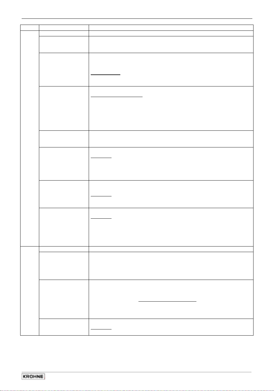
To change numbers
Full Scale Full Scale
2 8 2 7
m
[00849 – 33929] [00849 – 33929]
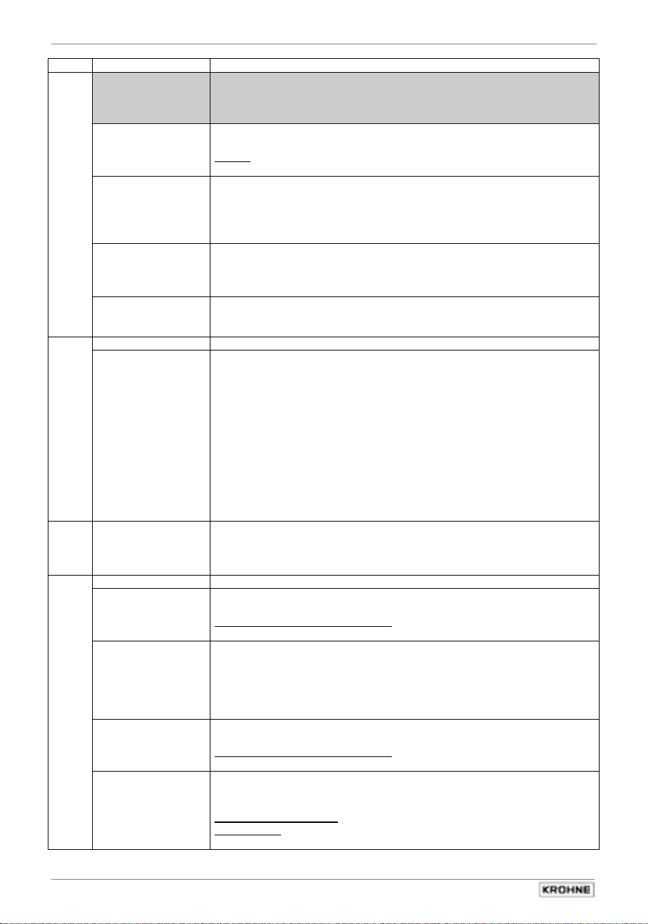
To revert to function display
Full Scale 1.06 Pulsoutput P
m3
1.02 Timeconstant
To terminate operator control
Press key ↵ repeatedly until one of the following menus
1.00 Operation, 2.00 Test or 3.00 Installation
3.00 Installation 3.00 Installation
2.00 Test 2.00 Test
1.00 Operation 1.00 Betrieb
2 8 3 7
[00849 – 33929] 1.03 Low Flow Cutoff
4
hr
4
hr 1.04 Display
Save
changes:
yes
increase number
3
→
m3
←
decrease number
1 x to several times Press key
↵
1.05 Currentoutput I
Press key ↵
↵
1 × ↑ )
2 × ↑ )
2 8 3 7
4
hr
↵
1.01 Full Scale
Store new parameters:
acknowledge by pressing key ↵.
Measuring mode continued with the
new parameters.
New parameters not to be stored:
Press ↑ key 1 or 2 times:
Save changes: return
= return to parameter setting
after pressing ↵ key.
Save changes: No
= new parameters not saved
after pressing ↵ key.
Continue measuring mode with “old“
parameters
IFC 210 E 29
05/2002
Page 30

Sect. 4.4 Part B IFC 210 Signal converter
4.4 Table of settable functions
Abbreviations used
B1/B2
DN
FM
F
F
FT
GK
I
I
0%
I
100%
I
max
P
P
P
I
Error
Status output, control input
Nominal size, meter size
Conversion factor volume for any unit,
see Fct. 3.05 “
Highest frequency of pulse output
max
Lowest frequency of pulse output
min
Conversion factor time for any unit,
see Fct. 3.05 “
Factor Volume
Factor Time
”
”
Primary constant
Current output
Current at 0% flow
Current at 100% flow
I Max.
Pulse output
= F
/ Q
max
min
max
= F
min
I Error, I
100%
/ Q
100%
≤
≥
I
I
0%
Error
max
Fct. Display- Texts Description and settings
1.00 OPERATION Operations menu
1.01 FULL SCALE Full-scale range for flowrate Q
Select unit
3
• m
/hr • Liter/Sec • US.Gal/min
• user unit, factory set is Liter/hr or US MGal/day (see Fct. 3.05)
Press
key to transfer to number setting.
→
Setting ranges:
The ranges are dependent on the meter size (DN) and the
flow velocity (v):
Nom. dia. /meter size v
• DN 2.5–1600 /
0.0237 – 401 080 US Gal/min
Press
key to return to Fct. 1.01 FULL SCALE.
↵
VALUE P Pulse value has been changed.
With the old pulse values the output frequency (F)
would have been exceeded or not reached.
P
min
= F
min
/ Q
100%
1.02 TIMECONST. Time constant
Select:: • ALL (applies to display and all outputs)
• ONLY Current output (only display, current and status outputs)
Press ↵ key to transfer to number setting.
Range: • 0.2 – 99.9 Sec
Press ↵ key to return to Fct. 1.02 TIMECONST.
1.03 L.F.CUTOFF Low-flow cutoff (SMU)
• OFF (fixed values: ON = 0.1% / OFF = 0.2%)
PERCENT (variable values) ON OFF
1 – 19% 2 – 20%
Press → key to transfer to number setting.
Note: Cutoff off value must be greater than cutoff on value.
Press ↵ key to return to Fct. 1.03 L.F. CUTOFF.
Q
Q
Q
Q
SMU
v
v
v
F/R
1
/10 – 64:
P
max
actual flowrate
100% flow = full scale range
100%
π
= DN2 × v
max
min
4
at v
π
= DN2 × v
4
at v
max
= 12 m/s
max
min
= 0,3 m/s
min
Low-flow cutoff for I and P
Flow velocity
Max. flow velocity (12 m/s / 40 ft/s) at Q
max
Min. flow velocity (0.3 m/s / 1 ft/s) at Q
min
Forward/Reverse flow at F/R operation
100%
π
Q
= DN2 × v
min
4
= 0,3 m/s (1 ft/s) v
min
0.0053 – 86 859 m
= F
/ Q
max
Check new values!
100%
(=max. full-scale range Q
/ 40 ft/s
)
(=min. full-scale range Q
/ 1 ft/s
)
π
Q
min
max
= DN2 × v
max
4
= 12 m/s (40 ft/s)
3
100%
/hr
100%
100%
100%
max
30
IFC 210 E
05/2002
Page 31
Part B IFC 210 Signal converter Sect. 4.4
Fct. Display-Texts Description and settings
1.04 DISPLAY Display functions
Contrast Set display contrast
• range from + 15 (high contrast) to - 15 (low contrast)
Press ↵ key to transfer to subfunction “Flow”.
Flow Set format for flow rate display
• #### • ### . # • ## . ## • # . #### • Auto
Press key
→ to move to unit selection.
Selection unit: • m3/hr • Liter/Sec • US Gal/min
user unit, factory set is Liter/hr or US MGal/day (see Fct. 3.05)
Press ↵ key to transfer to subfunction “Totalizer”.
Totalizer Set format for display of volume
Select decimal positions:
• ####### • ###### . # • ##### . ## • #### . ###
• ### . #### • ## . ##### • # . ###### • Auto
Press
→ key to move to unit selection.
• m3 • Liter • US Gal
user unit, factory set is Liter or US MGal (see Fct. 3.05)
Press ↵ key to transfer to subfunction “Messages”.
Messages Additional displays wanted in measuring mode?
• no • yes (overlay additional messages)
Press ↵ key to transfer to subfunction “Trend”.
Trend Set graphic display
Selection: • Average (show average values over time base)
• Min. & Max. (min./max. values over time base)
• Every Value (all values numbered consecutively)
Press ↵ key to transfer to subfunction “Updating”.
When
“every value“
selected, transfer to subfunction
“Scaling“.
Updating Update measured values in graphic display
(this not shown when “every value“, see above, selected)
Selection: • 0.1 Sec. • 0.2 Sec. • 0.5 Sec. • 1 Sec.
• 2 Sec. • 5 Sek. • 1 Min. • 2 Min. • 5 Min.
Press ↵ key to transfer to subfunction “Scaling”.
Scaling Set scaling of graphic display
Selection: • 0% ... 100% • - 25% ... 100%
• 0% ... 50% • 50% ... 100%
• -100% ... 0% • 25% ... -100%
• - 50% ... 0% • -100% ... - 50%
• Auto
Press
key to return to Fct. 1.04 DISPLAY.
↵
1.05 Current output I Set Current output I
Function Set Function
• Off (switched off)
• 1 Direction (1 flow direction)
• 2 Directions (forward/reverse flow, F/R flow measurement)
Range I Set measuring range (I0% ... I
Press ↵ key to transfer to subfunction “Range I”.
)
100%
• 0 - 20 mA • 4 - 20 mA (fixed ranges))
• mA (user-defined range)
• Range: I0% - I
(Value I0% < I
Press → key to transfer to number setting.
Press ↵ key to transfer to subfunction “I Max”.
!) 0 - 16 mA 4 - 20 mA
100%
100%
I Max Set I Max
Selection: • 20,5 mA • 22 mA
Press ↵ key to transfer to subfunction “I Error”.
IFC 210 E 31
05/2002
Page 32

Sect. 4.4 Part B IFC 210 Signal converter
Fct. Display- Texts Description and settings
I Error Set current for error identification (I
• 22 mA • 0.0 mA (... < I0%, variable only, see above ifI0% > 1 mA)
Reverse Range Set full-scale range for reverse flow
(appears only when 2 Directions selected, see above)
setting range: 005 - 150% of Q
(different value for reverse flow)
1.06 Pulsoutput P Set Pulsoutput P
Function Set Function
Selection: • Off (switched off)
• 1 Direction (1 flow direction)
• 2 Directions (forward/reverse flow, F/R flow measurement)
Pulswidth Set pulse width
Selection: • 0.01 - 1.00 Sec (only for F
• automatic (= 50% of the period duration)
of the 100% output frequency))
• symmetrical (= pulse duty ratio 1:1 over total range)
Pulsvalue Set pulse value
pulse value per unit
• PulS/ user-defined unit, factory-set is Liter or US
pulse value per unit
• PulSe/user-defined unit, factory-set is hr
1.07 Output/Input B1 Assignment of terminal B1 see Fct. 3.07 Hardware:
Either STATUS OUTPUT or CONTROL INPUT
For settings, refer to one of the following descriptions.
1.08 Output/Input B2 Assignment of terminal B2 see Fct. 3.07 Hardware:
Either STATUS OUTPUT or CONTROL INPUT
For settings, refer to one of the following descriptions.
1.0_ Status output Setting as status output
B1 and/or B2 • Off (status output switched off)
• On (status output switched on, e.g. as operation indicator)
EMPTY PIPE (signals that pipe is empty , only if option installed)
• SIGN.I or P (F/R flow measurement)
• Overflow I or P (overranging of outputs)
• SMU I or P (signals when low-flow cutoff is active)
• Inverse B1
Selection: • + direction • - direction • 2 directions
Setting range 005 - 150%
Setting range 05 - 80% (= ratio of lower to upper range)
• All Errors
• Fatal error only
Press → key to transfer to number setting.
Press ↵ key to transfer to subfunction “Range I”.
Press → key to transfer to number setting.
Press
key to return to Fct. 1.05 “Current output I”.
↵
Press ↵ key to transfer to subfunction “Pulswidth”.
Press ↵ key to transfer to subfunction “Pulsvalue”.
3
• 1/m
volume
time
Press
• Trip Point: (press key ↵ to transfer to Characteristics)
(press ↵ key to transfer to number setting)
• automatic range change (press ↵ key to transfer to number setting)
Press
key to return to Fct. 1.06 “Pulsoutput P”.
↵
key to return to Fct. 1.07 a
↵
• 1/Liter • 1/US Gal
M.Gal (see Fct. 3.05)
• PulSe/Sec (=Hz) • PulSe/min • PulSe/hr
(see Fct. 3.05)
)
Error
100%
max
nd/or 1.08 “
< 50 pulse/s)
}
Statusoutput”
I = I only
P = ALL
32
IFC 210 E
05/2002
Page 33

Part B IFC 210 Signal converter Sect. 4.4
Fct. Display-Texts Description and settings
1.0_ Controlinput Set as Control input
B1 and/or B2 • Off (switched off)
• Ext.Range (external range change)
Press ↵ key to transfer to number setting.
Setting range: 05 - 80% (= ratio of lower to upper range from
1:20 to 1:1.25. Value must be greater than that of Fct. 1.03 L.F. CUTOFF).
• Outp.Hold (hold value of outputs)
• Outp.Zero (set outputs to min.values)
• Total. Reset (reset totalizers)
• Error. Reset (delete error messages)
Press
key to return to Fct. 1.07 a
↵
nd/or 1.08 “
Statusoutput”
Fct. Display-Texts Description and settings
2.00 Test Test menu
2.01 Test Q Test measuring range Q
Precautionary query
• SURE NO
• SURE YES
Press ↵ key to return to Fct. 2.01 TEST Q .
Press → key to transfer to number setting.
select value: -110 / -100 / -50 / -10 / 0 / +10 / +50 / +100 / +110 PCT..
of set full-scale range Q
100%
.
Displayed value present at outputs I and P.
Press ↵ key to return to Fct. 2.01 “TEST Q” .
2.02 Hardwareinfo Hardware information and error status
Before consulting factory, please note down all codes.
Modul ADC X . X X X X X . X X
Y Y Y Y Y Y Y Y Y Y
Modul IO X . X X X X X . X X
Y Y Y Y Y Y Y Y Y Y
Press
key to transfer to next info.
↵
Modul DISP.. X . X X X X X . X X
Y Y Y Y Y Y Y Y Y Y
Modul RS X . X X X X X . X X (only provided if “computer interface”
Y Y Y Y Y Y Y Y Y Y Option installed)
2.03 Test Display
Press ↵ key to return to Fct. 2.02 “Hardwareinfo”.
Press → key to start test of display, duration approx. 5 sec.
Fct. Display-Texts Description and settings
3.00 Installation Installation menu
3.01 Language Select language for display texts
• GB / USA (English) • F (French)
• D (German) • others on request
Press ↵ key to return to Fct. 3.01 “Language”.
3.02 Flowmeter Set data for primary head
Diameter Select size from meter size table
• DN 2.5 - 3000 mm equivalent to 1/10 – 120 inch
Full Scale Full-scale range for flow Q
Select with ↑ key.
Press ↵ key to transfer to subfunction “Full Scale”.
100%
Selection unit: • m3/hr • Liter/Sec • US Gal/min
user unit, factory set is Liter/hr or US MGal/day (see Fct. 3.05)
Press → key to transfer to number setting.
Setting ranges:
The ranges are dependent on the meter size (DN) and the
flow velocity (v): Q
Nom. dia. /meter size V
= DN2 x v
min
= 0,3 m/s (1 ft/s) V
min
min
Q
= DN2 x v
max
= 12 m/s (40 ft/s)
max
max
• DN 2.5–1600 / 1/10 – 64: 0.0053 – 86 859 m3/hr
0.0237 – 401 080 US Gal/min
Press ↵ key to transfer to subfunction “Gk Value”.
IFC 210 E 33
05/2002
Page 34
Sect. 4.4 Part B IFC 210 Signal converter
Fct. Display-Texts Description and settings
Value P Pulse value has been changed.
With the old pulse values the output frequency (F)
would have been exceeded or not reached.
P
min
= F
min
/ Q
100%
P
max
= F
max
/ Q
Check new values!
100%
Gk Value Set primary constant GK
see primary head nameplate.
Range: • 1.0000 - 9.9999
Field Frequency Set Magnetic field frequency (f
Press ↵ key to transfer to subfunction “Field Frequency”.
= power frequency)
1
•
/2 × f
•
Net
Select with ↑ key.
1
/6 × f
Press ↵ key to transfer to subfunction “Flow Direction”.
Net
•
Net
1
/18 × f
•
Net
1
/36 × f
Net
for DC devices to subfunction „Line Frequency“
Line Frequency Normal line frequency in your country
This function is only provided for units with DC power supply
• 50 Hz • 60 Hz
Press ↵ key to transfer to subfunction “Flow Direction”.
Select with ↑ key.
Flow Direction Define flow direction (in F/R mode: forward flow).
• + Direction • - Direction
Press ↵ key to return to Fct. 3.02 “Flowmeter”.
Select with ↑ key.
3.03 Zero Point Zero calibration
• return (quit function without making change)
• calculate (calculate new zero value)
Press ↵ key to start, duration approx. 15-90 seconds.
Save new value, select with ↑ key:
• save no (do not save zero value)
• save yes (save new zero value)
• change (change zero value manually)
Press → key to transfer to unit selection:
• m3/h • Liter/s • US Gal/min
• any unit, see Fct. 3.05 (factory setting: Liter/h)
Value may be max. 10% of Q
Press ↵ key to return to Fct. 3.03 “Zero Point”.
Press → key to transfer to number setting.
100%
3.04 Entrycode Entry code required to enter setting mode?
• NO (= entry with → only)
• YES(= entry with → and Code 1:→ → → ↵ ↵ ↵ ↑ ↑ ↑ )
Press ↵ key to return to Fct. 3.04 “Entrycode”.
3.05 User Units Set any required unit for flowrate and counting
Text Volume Set text for required flowrate unit (max. 5 characters)
Factory-set: Liter or MGal .
Characters assignable to each place: • A-Z, a-z, 0-9, or — (= blank character)
Press ↵ key to transfer to subfunction “Factor Volumen”.
Factor Volume Set conversion factor (FM) for volume
Factory set 1.00000 for Liter or 2.64172E-4 for US MGal
(exponent notation, here: 1x 10³ or 2.64172x10⁻⁴).
Factor FM = volume per 1m3.
Setting range • 1.00000 E-9 to 9.99999 E+9 (= 10-9 to 10+9)
Press ↵ key to transfer to subfunction “Text Time”.
Text Time Set text for required time unit (max. 5 characters)
Factory-set: hr.
Characters assignable to each place: • A-Z, a-z, 0-9, or — (= blank character)
Press ↵ key to transfer to subfunction “Factor Time”.
Factor Time Set conversion factor (FT) for time
Factory-set: 3.60000 E+3 for hour or 8.64000 E+4 for day
(exponent notation, here: 3.6 x10³ or 8.64 x10⁻⁴).
Set factor FT in seconds.
Setting range • 1.00000 E-9 to 9.99999 E+9 (= 10-9 to 10+9)
Press ↵ key to return to Fct. 3.05 “User Units”.
34
IFC 210 E
05/2002
Page 35

Part B IFC 210 Signal converter Sect. 4.4
Fct. Display-Texts Description and settings
3.06 Application Set application conditions
Flow Set characterization for flow
• Steady (steady flow, max. 150% of Q
• Pulsating (pulsating flow, up to 1000% of Q
100%
)
100%
e.g. caused by reciprocating pumps, refer to Sect. 6.4)
Press ↵ key to transfer to subfunction “Empty Pipe”.
Empty Pipe Signal when measuring tube is empty (refer to Sect. 6.3 )
• no • yes (possible only with built-in option)
Press ↵ key to return to Fct. 3.06 “Application”.
3.07 Hardware Assign outputs and inputs to terminals B1 and B2
Terminal B1 Define function of terminal B1 (valid for Fct. 1.07)
• Statusoutput • Controlinput (
Press ↵ key to transfer to subfunction “Terminal B2”.
Select with ↑ key.
)
Terminal B2 Define function of terminal B2 (valid for Fct. 1.08)
• Statusoutput • Controlinput (
Press ↵ key to transfer to subfunction “Fieldcurrent”.
Select with ↑ key.
)
Fieldcurrent Define field current supply
• Intern
• Extern (> DN 1600 / > 64“ with power driver)
Press ↵ key to return to Fct. 3.07 “Hardware”.
3.08 Location Set measuring point tag
Factory setting: ALTOMETER
Characters assignable to each place:
• A-Z, a-z, 0-9 or „-“ (=blank character).)
Press ↵ key to return to Fct. 3.08 “Location”.
3.09 Communication Set comminucation interface
• Off (switched off))
• HART (HART®-interface switched on))
• KROHNE (KROHNE RS 485-interface switched on),
(only provided if daughter board installed (option).)
• Address: „HART“ 00-15 / „KROHNE“ 000-239
• Baud rate: 1200, 2400, 4800, 9600 or 19200
(appears with selection “KROHNE” only)“)
Press ↵ key to return to Fct. 3.09 “Communication”.
IFC 210 E 35
05/2002
Page 36

Sect. 4.5 Part B IFC 210 Signal converter
4.5 Error messages in measuring mode
The following list gives all errors that can occur during process flow measurement. Errors shown
in display when “Yes” set in Fct. 1.04 Display, subfunction “Messages.”.
Error messages Description of error Error clearance
Line Int. Power failure Note:
no counting during power failure
Overflow I Current output overranged
(Flow > I Max)
Overflow P Pulse output overranged.
(Flow > I Max)
Totalizer Totalizer has been reset. Cancel error message in
ADC Analog / digital
converter overranged
Fatal Error Fatal error, all outputs set
to “min. values“
Empty Pipe Pipe has run dry.
This message appears only when
the “empty pipe identifier”
option is installed and the function
is switched on under Fct. 3.06
Application, submenu ”Empty Pipe”.
Cancel error in Reset-Quit menu, see
Sect. 4.6.
Reset totalizer if necessary.
Check and if necessary correct
instrument parameters. After
elimination of cause, error message
deleted automatically.
Check and if necessary correct
instrument parameters. After
elimination of cause, error message
deleted automatically.
Reset/Quit. menu, see Sect. 4.6.
Error message deleted automatically
after elimination of cause.
Please consult factory.
Fill pipe.
36
IFC 210 E
05/2002
Page 37

Part B IFC 210 Signal converter Sect. 4.6
4.6 Reset totalizer and cancel error messages
Cancel error messages in RESET / QUIT menu
Key Display Description
- - - - - - - - - - - - / - - - Measuring mode
↵
↑ →
... No Do not delete error messages,
↑
↵
↵
Reset totalizer(s) in RESET / QUIT menu
Key Display Description
- - - - - - - - - - - - / - - - Measuring mode
↵
↑ →
↵
→
↑
↵
Code 2 - -
Error Quit .... Menu for error acknowledgement
... Yes Delete error messages
Reset totalizer …
- - - - - - - - - - - - / - - - Return to measuring mode
Code 2 - -
Error Quit .... Menu for error acknowledgement
Reset totalizer … Menu for resetting totalizer
... No Do not delete error messages,
... Yes Reset totalizer
- - - - - - - - - - - - / - - - Return to measuring mode
Key in entry code 2 for Reset / Quit
menu: ↑ →
press ↵ twice = return to measuring mode.
Key in entry code 2 for Reset / Quit
menu: ↑ →
press ↵ twice = return to measuring mode.
4.7 Examples of setting the signal converter
As an example the cursor, flashing part of display, is shown below in bold type.
•
Change measuring range of current output and value for error messages (Fct. 1.05):
•
Change measuring range from 04-20 mA to 00-20 mA
•
Change value for error messages from 0 mA to 22 mA
Key Display Description
→
Fct. 1.00 Operation
→
4 × ↑
→
→ ↵
→
2 × ↑
2 × ↵
→
↑
↵
↵
↵
↵
If “Yes” set under Fct. 3.04 Entry Code, key in the
9-keystroke Code 1 now: → → → ↑ ↑ ↑ ↵ ↵ ↵
Fct. 1.01 Full Scale
Fct. 1.05 Current output I
Function
Range I
04-20 mA Old current range
00-20 mA New current range
I Error
0 mA Old value for error messages
22 mA New value for error messages
Fct. 1.05 Current output I
Fct. 1.00 Operation
Store Yes
- - - - - - - - - - - - / - - - Measuring range with new data for the current output
IFC 210 E 37
05/2002
Page 38

Sect. 5.1 Part B IFC 210 Signal converter
'HVFULSWLRQRIIXQFWLRQV
5
5.1 Full-scale range Q
(Fct. 1.01)
100%
Fct. 1.01 FULL SCALE
Press → key.
Choice of unit for full-scale range Q
m3/hr
•
Liter/Sec
•
US Gal/min
•
User-defined unit, factory-set is „
•
Select with
Use
↑
or
↓
→
key to transfer to numerical setting, 1st number (cursor) flashes..
Set full-scale rangeQ
(cubic metres per hour)
(litres per second)
(US gallons per minute)
key.
100%
100%
Liter/hr
“ (litres per hour) or “
US MGal/day
”, see Sect. 5.07
The setting range is dependent on meter size (DN) and flow velocity (v).
Q
π
= DN2 × v
min
4
min
Q
0.00531 – 86 858 m
π
= DN2 × v
max
4
(refer to flow table in Sect. 10.2)
max
3
/hr
0.00147 – 24 120 Liter/Sec
0.02335 – 382 420 US Gal/min
Change flashing number (cursor) with ↑ or ↓ key.
→
Use
Press
Note
key to shift cursor 1 place to right.
↵
key to return to Fct. 1.01 Full Scale.
if “
Pulsvalue
” is displayed after pressing ↵ key:
Pulse/Vol. is set under Fct. 1.06 Puls B1, subfunction “Select P”. Due to the changed full-scale
range Q
= F
P
min
Change pulse value accordingly, see Sect. 5.7 pulse output P, Fct. 1.06.
the output frequency (F) of the pulse output will be over- or undershot:
100%,
min
/ Q
100%
= F
P
max
max
/ Q
100%
5.2 Timeconstant (Fct. 1.02)
Fct. 1.02 Timeconstant
Press → key.
Choice
All
•
Only I
•
Select with
Transfer to number setting with
Set numerical value
0.2 - 99.9 Sec
•
Change flashing number (cursor) with ↑ or ↓ key.
Use
→
Press
38
IFC 210 E
(applies to display and all outputs)
(applies only to display, current and status output)
↑
or
key.
↓
↵
key. 1st number (cursor) flashes.
(seconds)
key to shift cursor 1 place to right.
↵
key to return to Fct. 1.02 Timeconstant.
05/2002
Page 39

Part B IFC 210 Signal converter Sect. 5.3
5.3 Low Flow Cutoff (Fct.1.03)
Fct. 1.03 Low Flow Cutoff)
Press
→
key.
Choice
Off
•
Percent
•
Select with
↑
Transfer to number setting using
fixed tripping point:: ON = 0.1 % / OFF = 0.2 %
variable tripping points: ON = 1 - 19 % / OFF = 2 - 20 %
or
↓ key.
→
key (only if “PERCENT” selected).
1st number (cursor) flashes.
Setting the numerical value when “Percent” selected
01 to 19
•
02 to 20
•
Note: The cutoff “off” value must be greater than the cutoff “on” value.
(cutoff “on” value, left of hyphen)
(cutoff “off” value, right of hyphen)
Change flashing number (cursor) with ↑ or ↓ key.
→
Use
Press
key to shift cursor 1 place to right.
↵
key to return to Fct. 1.03 Low Flow Cutoff.
5.4 Internal electronic totalizer
The internal electronic totalizer counts in m3, regardless of the unit set under Fct. 1.04,
subfunction “totalizer”.
The counting range is dependent upon the meter size and has been selected such that the
totalizer will count for a minimum of 1 year without overflow:
Meter size Counting range
DN mm inch in m3 US Gal equivalent
2.5 - 50
65 - 200 21/2 - 8 0 - 9 999 999.9999999 0 - 2 641 720 523.5800
250 - 600 10 - 24 0 - 99 999 999.999999 0 - 26 417 205 235.800
700 -1600 28 - 64 0 - 999 999 999.99999 0 – 264 172 052 358.00
Only part of the totalizer count is shown in the display because it is not possible to output
a 14-digit number. Unit and format of the display are freely selectable, see Fct. 1.04, subfunction
“totalizer” and Sect. 5.5. This determines which part of the count is to be displayed.
Display overflow and totalizer overflow are independent of one another.
Example
Internal count 0000123 . 7654321 m3
Format, display unit XXXX . XXX Liter
Internal count in unit 0123765 . 4321000 Liter
Displayed 3765 . 432 Liter
1
/10 - 2 0 - 999 999.99999999 0 - 264 172 052.35800
IFC 210 E 39
05/2002
Page 40

Sect. 5.5 Part B IFC 210 Signal converter
5.5 Display (Fct. 1.04)
Fct. 1.04 Display
Press
→
key.
Contrast = set required contrast
Range adjustable from +15 (high contrast) to –15 (= low contrast)
•
Change setting with ↑ or ↓ key,
↵
Press
Flow = set required flow unit and number format
•
•
•
•
•
•
•
•
•
Select with
Press
Totalizer = set required totalizer unit and number format
•
•
•
•
•
•
•
•
•
•
•
•
Select with
Press
key to transfer to subfunction “flow“.
Auto
# . ####
## . ##
### . #
####
m3/hr
Liter/Sec
US Gal/min
User-defined unit, factory setting = Liter/hr (litres per hour) or US MGal/day , see Sect. 5.17
↑
or
↵
key to change to subfunction “totalizer”.
Auto
# . ######
## . #####
### . ####
#### . ###
##### . ##
###### . #
#######
m3
Liter
US. Gal
User-defined unit, factory setting = Liter (litres) or US MGal/day , see Sect. 5.17
↑
or
↵
key to change to subfunction “messages”.
(= exponent notation)
Change setting with ↑ or ↓ key,
Transfer to Unit Selection with
(cubic metres per hour)
(litres per second)
(US gallons per minute)
↓ key.
(= exponent notation)
Change setting with ↑ or ↓ key,
Transfer to Unit Selection with
(cubic metres)
(litres)
(US gallons)
↓ key.
→
→
key.
key.
40
IFC 210 E
05/2002
Page 41

Part B IFC 210 Signal converter Sect. 5.5
Messages= additional messages desired in measuring mode
•
No
•
Yes
measured values)
Select with
Press
Trend = set graphic display (trend)
•
Mean values
•
Min. & Max.
•
Every value
↑
or
↵
key to change to subfunction “Trend”.
(no additional messages)
(display additional messages, e.g. errors, in sequence with
↓
key.
Show mean values over time base
Min./Max. values over time base
All values numbered consecutively
Select with ↑ or ↓ key.
↵
Press
Updating = update measured values in the graphic display
(This selection not shown when “every value” selected, see above)
Selection:
• 5 sec. • 1 min. • 2 min. • 5 min.
Select with ↑ or
Press
Scaling = Set scaling of graphic display
Selection:
Select with
Press
key to transfer to subfunction “Updating“.
• 0.1 sec. • 0.2 sec. • 0.5 sec. • 1 sec. • 2 sec.
↓
key.
↵
key to transfer to subfunction “Scaling“
• Auto • 0% ... 100% • -100% ... 0 % • -25% ... 100% • -100% ... 25%
• 0% ... 50% • - 50% ... 0% • 50% ...100% • -100% ... - 50%
↓ key.
↑
or
↵
key to return to Fct. 1.04 Display
Please refer to Section 3.2 Factory settings
IFC 210 E 41
05/2002
Page 42

Sect. 5.6 Part B IFC 210 Signal converter
5.6 Currentoutput I (Fct. 1.05)
Fct. 1.05 Currentoutput I
Press
→
key.
Function = Select function for current output,
Odd
•
1 Direction
•
2 Directions
•
Select with
Press
↑
or
↵
key to change to subfunction “Range I”.
Exceptions: When “Off” selected, return to Fct. 1.05 Currentoutput I.
Range I = select measuring range (I0% - I
0 - 20 mA
•
4 - 20 mA
•
mA (user-defined value)
•
0...16 mA – 4...20 mA
Press
→
key to transfer to number setting.
↑
Select with
Press
I Max = Set (I
20.5 mA
•
Select with
Press
I Error = set error value, (I
22 mA
•
0.0 - I0% mA
•
Select with
Press
Reverse Range = define full-scale range for reverse flow
XXX . XX %
•
or
↵
key to change to subfunction “I Max”.
max
↑
or
↵
key to change to subfunction “I Error”.
↑
or
↵
key to change to subfunction “Reverse Range”.
Change negative-image number (cursor) using ↑ or ↓ key,
Move cursor 1 place to right with
Press
↵
key to return to Fct. 1.05 Currentoutput I
Refer to Sect. 2.5 for connection diagrams, and to Sect. 5.22 for characteristics.
switched off, no function
1 flow direction
2 flow directions, F/R mode, forward/reverse
↓ key.
)
key.
100%
– I
(Wert I0% < I
100%
100%
fixed ranges
}
I
0%
↓ key.
)
• 22 mA
↓ key.
)
Error
(fixed value)
variable value; only variable when I0% > 1 mA, see “Range I” above)
↓ key.
5 - 150 % of full-scale range for forward flow
→
Please refer to Sect. 3.2 Factory settings .
!)
42
IFC 210 E
05/2002
Page 43

Part B IFC 210 Signal converter Sect. 5.7
5.7 Pulsoutput P (Fct. 1.06)
Fct. 1.06 Pulsoutput P
Press
→
key.
Function = select function for pulse output,
Off
•
1 Direction
•
2 Directions
•
Select with
Press
↑
or
↵
key to change to subfunction “Pulswidth”.
Exceptions: When “Off” selected, return to Fct. 1.06 Pulsoutput P.
Pulswidth = Set puls width
0.01 – 1.00 s
•
Automatic
•
Symmetric
•
Please note !
= 10 pulses/hr
F
min
F
=
max
×
switched off, no function
1 flow direction
2 flow directions, F/R mode, forward/reverse
↓ key.
Only for F
(select this function when operating with EMC.)
= 50 % of cycle duration of 100 % output frequency
= pulse duty factor 1:1 across entire range
1
width[s]Puls2
< 50 pulses
max
≤ 10 kHz, if „automatic” or „symmetric is selected under
subfunction Pulswidth.
Select with
Press
Pulse value = set pulse value
Pulses per unit volume
Pulses per unit time
Select with
Press
Refer to Sect. 2.5 for connection diagrams, and to Sect. 5.22 for characteristics.
↑
or
↓ key.
↵
key to change to subfunction “Pulsvalue”.
1/m³
•
any unit, see Fct. 3.05, factory-set is ”Pulses per Liter“
•
↑
or
↓ key.
↵
key to return to Fct. 1.06 Pulsoutput P
1/s (= Hz)
•
any unit, see Fct. 3.05, factory-set is Pulses per hour
•
Please refer to Sect. 3.2 Factory settings .
•
•
1/Liter
1/min
•
•
1/US Gal
1/h
IFC 210 E 43
05/2002
Page 44
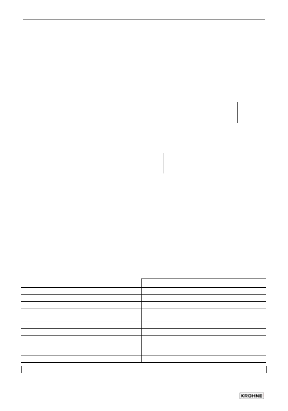
Sect. 5.8 Part B IFC 210 Signal converter
p
5.8 Statusoutput B1 and / or B2
Statusoutput: Fct. 1.07 (output terminal B1) and Fct. 1.08 (output terminal B2)
Press
→
key.
Select function of status outputs,
Off
•
On
•
All Error
•
Only Fatal
•
Signum
•
I or P
Overrange I or P
•
Low Flow Cutoff
•
I or P
Invers B1
•
Trip Point
•
Define flow direction (characteristics) for limit value
Define limit value NO contact: XXX > YYY
XXX - YYY NC contact: XXX < YYY
0...150% - 0...150% Hysteresis: Difference XXX to YYY
switched off, no function
indicates that flowmeter is operative
indicates all errors
indicates fatal errors only
for V/R mode, measurement in both flow directions,
see also Sect. 5.10
signals overranging of outputs
signals active low-flow cutoff (SMU)
Status output B2 inverse function to B1
(only provided if B1 and B2 are set as status output)
see also Sect. 5.12
• + direction
• - direction
• 2 directions
Transfer to number setting with
1st number (cursor)with negative image.
•
Auto Range
Setting range: 05 – 80 %
ratio of upper to lower range, 1:20 to 1:1.25
(value must be greater than that of Fct. 1.03 L.F.Cutoff , s. also Sect. 5.3)
Empty Pipe
•
Change negative-image number (cursor) with ↑ or ↓ key, move
cursor 1 place to right or left with → and ← key, resp..
see also Sect. 5.11
Signals that tube is empty (only with built-in option), see Sect. 6.4 – 6.6.
Select with
↑
or
↓ key.
Select with
↵
I = I only
P = All
↑ or ↓ key
key,
Press ↵ key to return to Fct. 1.07 or 1.08 Statusoutput.
Characteristics of status outputs
Off (switched off) no function
On (e.g. operation indicator) power OFF power ON
Empty Pipe Tube is empty Tube is full
Signum I or P Forward flow Reverse flow
Overflow I or P not overranged overranged
Low Flow Cutoff I or P inactive active
Invers B1 B2 closed B2 open
Trip Point (limit switch) inactive active
Auto Range high range low range
All Error (all errors) errors no error
Only Fatal (fatal errors only) errors no error
Please refer to Sect. 3.2 Factory settings .
Refer to Sect. 2.5 for connection diagrams, and to Sect. 5.22 for characteristics.
44
IFC 210 E
Switch o
en Switch closed
05/2002
Page 45
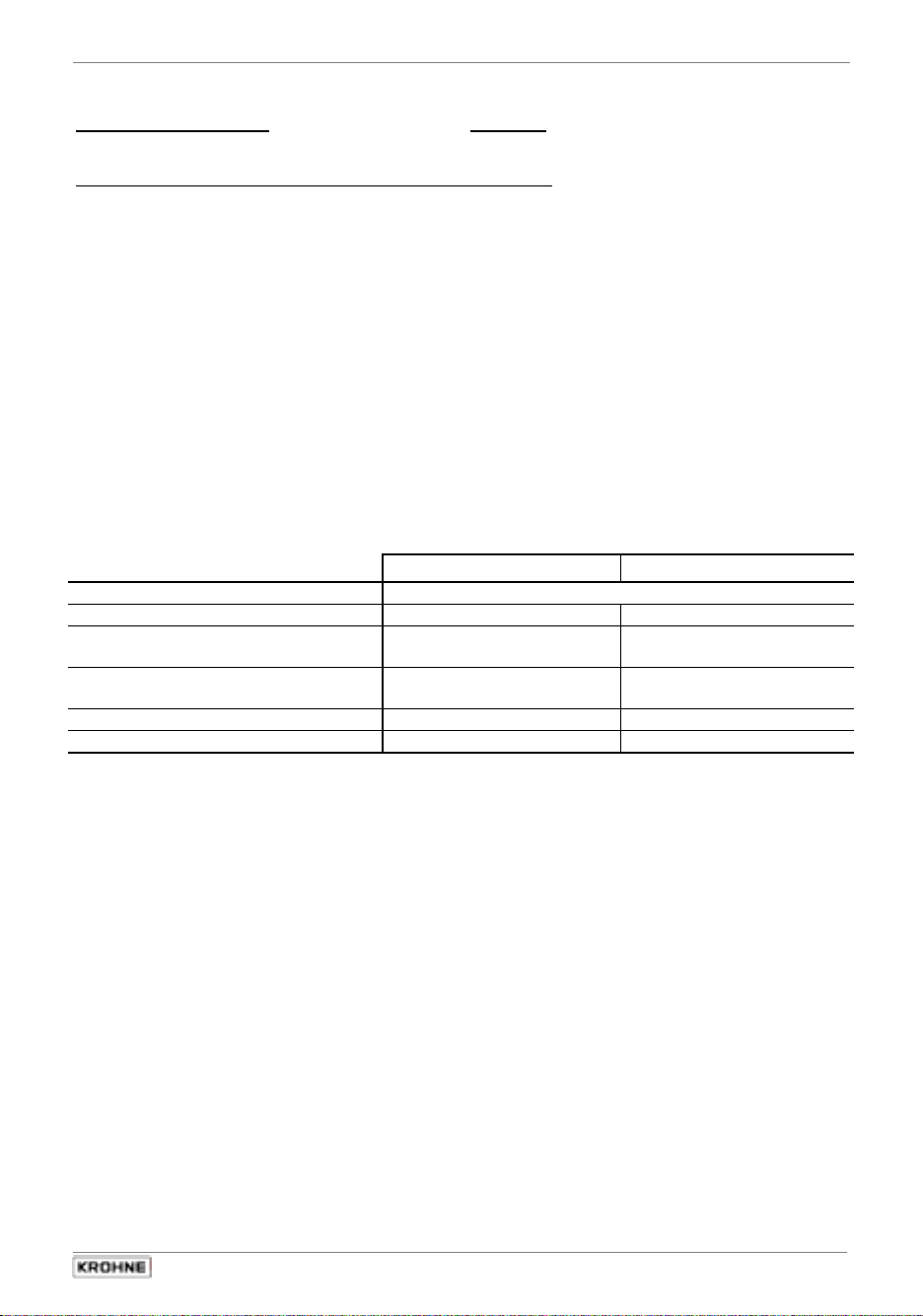
Part B IFC 210 Signal converter Sect. 5.9
(
5.9 Controlinput
Controlinput: Fct. 1.07 (output terminal B1) and Fct. 1.08 (output terminal B2)
Press
→
key.
Select function of control inputs,
Off
•
Hold Value
•
Zero Value
•
Total Reset
•
Error Reset
•
Extern Range
•
Select with
↑
or
↓ key.
switched off, no function
hold value of outputs and display
set outputs and display to “min. values”
reset totalizers
delete/acknowledge error messages
external range change
setting range: 05 – 80 %
ratio of high to low range, 1:20 to 1:1,25, (value must be greater
than that of Fct. 1.03 L.F.Cutoff, s. also Sect. 5.3)
Press ↵ key to return to Fct. 1.07 or 1.08 Statusoutput.
Characteristics of status inputs
Transfer to number setting with
1st number (cursor)with negative image.
↵
key,
Change negative-image number (cursor) with ↑ or ↓ key, move
cursor 1 place to right or left with → and ← key, resp..
inactive
no voltage) active (voltage present)
Off no function
Extern Range high range low range
Hold Value Measured values follow the
Hold measured values
measurement
Zero Value Measured values follow the
measurement
Set measured values to
“zero”
Total Reset inactive Reset totalizer
Error Reset inactive Delete error messages
5.10 F/R mode, forward/reverse flow measurement
Refer to Sect. 2.5 for electrical connection of outputs.
•
Define direction of forward (normal) flow, see Fct. 3.02, subfunction Flow Dir. :
•
in conjunction with F/R operation, set the direction for the forward flow here.
„+“ signifies the same direction as shown by the arrow on the primary head,
„-“ signifies the opposite direction.
Set the status output to SIGN I or SIGN P , see Fct. 1.07.
•
Current and/or pulse output must be set to 2 Directions,
•
see Fct. 1.05 and/or 1.06, subfunction “Function”.
IFC 210 E 45
05/2002
Page 46
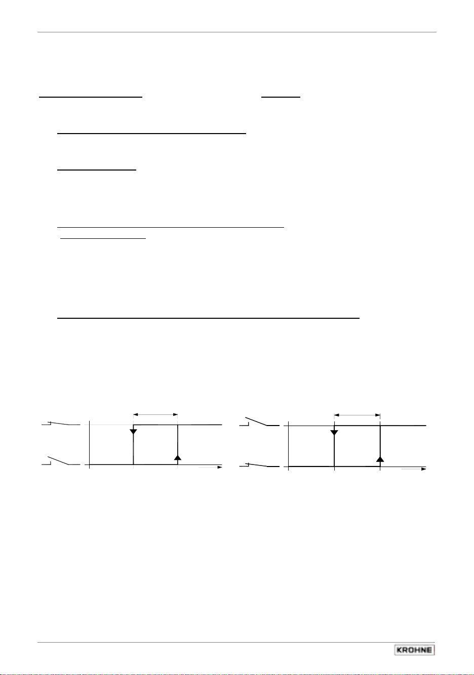
Sect. 5.11 Part B IFC 210 Signal converter
5.11 Set limit values (status output B1 and/or B2)
(Before the following settings can be carried out, set the “Status output” mode for output
terminals B1 and/or B2 in Fct. 3.07, see Sect. 5.19.)
Status output: Fct. 1.07
Press
→
key.
•
(output terminal B1) and / or Fct. 1.08 (output terminal B2)
•
Set Function ”Trip Points“
•
•
↵
Press
key.
Set flow direction:
with
↑
or
↓ key.
+ direction
– direction
2 directions
•
•
↵
Press
key.
Set Trip Point, cursor for the 1st digit shown negatively.
Display: XXX - YYY
Set with ↑ or ↓ keys..
Use → key to shift cursor 1 place to right.
Setting ranges for XXX and YYY: 0 – 150 % of Q
hysteresis ≥ 1%
full-scale range
100%
(=difference between XXX and YYY value)
Press ↵ key to return to Fct. 1.07 or 1.08 Statusoutput.
•
Switching behaviour (N/O or N/C contact) and hysteresis are adjustable.
•
N/O contact: XXX- value > YYY- value N/C contact: XXX- value < YYY- value
Switch closes when flow
exceeds XXX value
Switch opens when flow
exceeds YYY value
Example 1: XXX = 55% Example 2: XXX = 45%
YYY = 45% YYY = 55%
hysteresis = 10% hysteresis = 10%
YYY hysteresis XXX
YY XXX
Y
YYY hysteresis XXX
YYXXX
Y
45% 55% Q
45% 55%
Q
45% 55%
45% 55% Q
Please note !: When the two status outputs B1 and B2 are activated (see Sect. 5.19),
min. and max. values can, for example, be signalled.
46
IFC 210 E
05/2002
Q
Page 47

Part B IFC 210 Signal converter Sect. 5.12
5.12 Automatic range change BA (with status output B1 or B2)
and external range change (with control input B1 or B2)
1. Description of automatic range change BA and external range change
The automatic range change BA has two measuring ranges that are automatically changed
over as a function of the flow rate. The ratio between low and high range is adjustable
between 1:20 and 1:1.25, equivalent to 05 – 80% of Q
- changeover from high to low range: at approx. 85% of the low range
- changeover from low to high range: at approx. 98% of the low range
F/R flow operation is also possible, direction then identified via the 2nd status output.
In the case of external range change, changeover from high to low range (and conversely
from low to high range) is effected by the control input being activated by an external pulse.
2. Automatic range change BA by one of the status outputs B1 or B2
(Before the following settings can be carried out, the ”status output” mode for output terminal B1
or B2 must be set in Fct. 3.07, see Sect. 5.19.)
Status output: Fct. 1.07
•
Press
→
key.
(terminal B1) or Fct. 1.08 (terminal B2)
(full-scale range).
100%
•
Set Function ”Auto Range“
•
Press
↵
key.
•
Set Range Value, cursor for the 1st digit shown negatively.
with
↑
or
↓ key.
Set with ↑ or ↓ keys.
Use → key to shift cursor 1 place to right.
Setting range 05 – 80% of Q
full-scale range
100%
(ratio between low and high range between 1:20
and 1:1,25)
•
Press ↵ key to return to Fct. 1.07 or 1.08 Statusoutput.
3. External range change by one of the control input B1 or B2
(Before the following settings can be carried out, the ” control input” mode for output terminal B1
or B2 must be set in Fct. 3.07, see Sect. 5.19.)
Control input: Fct. 1.07
•
Press
→
key.
•
Set Function ”Extern Range“
•
Press
↵
key.
•
Set Range Value, cursor for the 1st digit shown negatively.
(terminal B1) or Fct. 1.08 (terminal B2)
↑
with
↓
or
key.
Set with ↑ or ↓ key.
Use → key to shift cursor 1 place to right.
Setting range 05 – 80% of Q
full-scale range
100%
(ratio between low and high range between 1:20
and 1:1,25)
•
Press ↵ key to return to Fct. 1.07 or 1.08 Statusoutput.
Please note: Only one of the two functions can be used.
Automatic range change and external range change act only on the current output.
IFC 210 E 47
05/2002
Page 48

Sect. 5.13 Part B IFC 210 Signal converter
5.13 Language (Fct. 3.01)
Fct. 3.01 Language
Press
→
key.
Select language for texts in display
↑
(German)
(English)
(French)
or
↓ key.
D
•
GB/USA
•
F
•
others on request
•
Select with
Press
↵
key to return to Fct. 3.01 Language.
5.14 Zero check (Fct. 3.03)
Set zero flow in the pipeline, but make sure that the measuring tube is completely filled
•
with fluid.
Switch on the system and wait 15 minutes.
•
Press the following keys for zero measurement:
•
Key Display Description
→
Fct. 1.00 Operation
2x ↑
→
2x ↑
→
↑
↵
Store No
measuring mode.
↑
↵
(2x) 3x ↵
If “Yes” set under Fct. 3.04 ENTR Y CODE, key in
9-keystroke CODE 1 now: → → → ↵ ↵ ↵ ↑ ↑ ↑
Fct. 3.00 Installation
Fct. 3.01 Language
Fct. 3.03 Zero Point
back
enquire
0.00 - - - - - / - - - Zero measurement in progress, duration approx. 50 seconds.
When flow > 0 WARNING notice appears, confirm with ↵ key.
If new value not to be stored, press ↵
Store Yes
Fct. 3.03 Zero Point Store new zero value.
- - - - - - - - - - - - / - - - Measuring mode with new zero.
key (3x) 4x = return to
5.15 Determine Entry Code (Fct. 3.04)
Fct. 3.04 Entry Code
Press
→
key.
Choice
No
•
Yes
•
Select with
Press
↑
or
↵
key to return to Fct. 3.04 Entry Code.
48
IFC 210 E
(no code, enter setting mode with → key)
(enter setting mode with → key and Code 1: → → → ↵ ↵ ↵ ↑ ↑ ↑)
↓ key.
05/2002
Page 49

Part B IFC 210 Signal converter Sect. 5.16
5.16 Primary head – Set data (Fct. 3.02)
Fct. 3.02 Flow Meter
Press
→
key.
Diameter = set meter size (see instrument nameplate)
Select size from table of meter sizes:
DN 2.5 - 1600 mm equivalent to 1/10 - 64 inch
Select using ↑ or
Transfer to subfunction “Full Scale
Full Scale = set full-scale range
Set as described in Sect. 5.1.
Note: if “Pulsvalue” is displayed after pressing ↵ key.
Pulse/Vol. is set under Fct. 1.06 Pulsoutput P, subfunction “Pulsvalue” . Because the full-scale
range Q
P
Change pulse value accordingly, see Sect. 5.7 Pulseoutput P, Fct. 1.06.
Press ↵ key to change to subfunction “GK Value”.
min
= F
100%
min
/ Q
GK Value = set primary constant GK,
1.0000 - 9.9999 (note information on instrument nameplate, do not change setting !)
•
Change flashing digit (cursor) with ↑ or ↓ key.
Shift cursor 1 place to right or left with
↵
Press
key to change to subfunction “Field Frequency”.
Field Frequency = set magnetic field frequency
1/2
•
1/6
•
Select with
Press
↑
↵
key to change to subfunction “Flow Direction”.
(only for units with DC power supply, transfer to subfunction “Line Frequency”).
Line Frequency = normal line frequency in your country
(Please note, applicable for flowmeters equipped with DC in power supply!)
50 Hz
•
60 Hz
•
Flow Direction = set flow direction
+ Direction
•
– Direction
•
Select with - or ¯ key.
Press ↵ key to return to Fct. 3.02 Flow Meter.
Zero check, see Fct. 3.03 in Sect. 5.14 or in Sect. 7.1.
↓ key.
” with ↵ key.
has been changed, the output frequency (F) of the pulse output is over- or undershot:
•
•
100%
1/18
1/36
or
P
↓ key.
Select with
= F
max
max
/ Q
→
100%
or ← key.
(1/2, 1/6, 1/18 or 1/36 of power frequency, see instrument nameplate,
do not change setting !)
↑
or
↓ key.
Press ↵ key to change to subfunction “Flow Direction”.
(for identification of flow direction, see “+ arrow” on primary head;
for F/R mode, identifies the positive flow direction)
Please refer to Sect. 3.2 Factory settings .
IFC 210 E 49
05/2002
Page 50

Sect. 5.17 Part B IFC 210 Signal converter
5.17 User-defined unit (Fct. 3.05)
Fct. 3.05 User Units
Press
→
Text Volume = set text for user-defined unit
•
Characters assignable to each place: A-Z, a-z, 0-9, or „–“ (=blank character)
Change flashing digit (cursor) with ↑ or ↓ key.
Shift cursor 1 place to right or left with
Press
Factor Volume = set factor FM set factor
•
Setting range: 1.00000 E-9 to 9.99999 E+9 ( = 10-9 to 10+9)
Change flashing digit (cursor) with ↑ or ↓ key.
Shift cursor 1 place to right or left with
Press
Text Time = set text for required time
•
Characters assignable to each place:
Change flashing digit (cursor) with ↑ or ↓ key.
Shift cursor 1 place to right or left with
Press
Factor Time = set factor FT for time
•
Setting range: 1.00000 E-9 to 9.99999 E+9 ( = 10-9 to 10+9)
Change flashing digit (cursor) with ↑ or ↓ key.
Shift cursor 1 place to right or left with
Press
Factors for volume FM (factor FM = volume per 1 m3)
Volumetric unit Text examples Factor FM Setting
Cubic metres
Litres
Hectolitres
Decilitres
Centilitres
Millilitres
US gallons
Millions US gallons
Imperial gallons
Mega imperial gallons
Cubic feet
Cubic inches
US barrels liquid
US barrels ounces
Factors for time FT (factor FT in seconds)
Time unit Text examples Factor FT (seconds) Setting
Seconds
Minutes
Hours
Day
Year (= 365 days)
50
key.
Liter
↵
key to change to subfunction “Factor Volume”.
1.00000 E+3
↵
key to change to subfunction “Text Time”.
hr
↵
key to change to subfunction “Factor Time”.
3.60000 E+3
↵
key to return to Fct. 3.05 User Units.
(max. 5 characters, factory-set: Liter or US MGal )
→
or ← key.
(factory-set: 103 or 2.64172 x 10⁻⁴ / factor FM = volume per 1 m3)
→
or ← key.
(max. 3 places, factory-set: hr = hour or day )
→
or ← key.
(factory-set: 3.6 x 10³ for hour or 8.64 x 10⁴ for day / set factor FT in seconds)
→
or ← key.
3
m
Liter
h Lit
d Lit
c Lit
m Lit
USGal
USMG
GBGal
GBMG
3
Feet
3
inch
US BaL
US BaO
Sec
min
hr
Day
Yr
1.0
1 000
10
10 000
100 000
1 000 000
264.172
0.000264172
219.969
0.000219969
35.3146
61 024.0
8.36364
33 813.5
1
60
3 600
86 400
31 536 000
IFC 210 E
A-Z, a-z, 0-9, or „–“ (=blank character)
1.00000 E+0
1.00000 E+3
1.00000 E+1
1.00000 E+4
1.00000 E+5
1.00000 E+6
2.64172 E+2
2.64172 E-4
2.19969 E+2
2.19969 E-4
3.53146 E+1
6.10240 E+4
8.38364 E+0
3.38135 E+4
1.00000 E+0
6.00000 E+1
3.60000 E+3
8.64000 E+4
3.15360 E+7
05/2002
Page 51

Part B IFC 210 Signal converter Sect. 5.18
5.18 Application (Fct. 3.06)
Fct. 3.06 Application
Press
→
key.
Flow = Set characterization for the flow
steady
•
pulsating
•
flow is steady, max. 150 % of Q
pulsating flow, = up to 1000 % of Q
reciprocating pumps,
100%
100%
, e.g. due to
Select with
↑
or
↓ key.
see also Sect. 6.4 - 6.6.
Press ↵ key to return to Fct. 3.06 Application.
Empty pipe = signals that measuring tube is empty (possible only with built-in option)
No
•
Yes
•
Select with
↑
or
↓ key.
see also Sect. 6.4 - 6.6.
Press ↵ key to return to Fct. 3.06 Application.
5.19 Hardware (Fct. 3.07)
Assignment of terminals B1 + B2 and field current supply
Fct. 3.07 Hardware
Press
→
key.
Terminal B1 = define function of terminal B1 (valid for Fct. 1.07)
Statusoutput
•
Press ↵ key to change to subfunction “Terminal B2”.
Terminal B2 = define function of terminal B2 (valid for Fct. 1.08)
Statusoutput
•
Press ↵ key to change to subfunction “Fieldcurrent”.
Field current = define field current supply
Intern
•
Press ↵ key to return to Fct. 3.07 Hardware.
Please note:
Only correct settings will give accurate measurement results.
The setting “external” is only required if a field current power driver is connected.
Controlinput
•
Controlinput
•
Extern (> DN 1600 / > 64”)
•
Select with
Select with
Select with
↑
↑
or
or
↑
↓ key.
↓ key.
or
↓ key.
IFC 210 E 51
05/2002
Page 52

Sect. 5.20 Part B IFC 210 Signal converter
5.20 Measuring point identification – Location (Fct. 3.08)
Fct. 3.08 Location
Press
→
key.
Set measuring point identification using max. 10 characters, (e.g. TQ1_532197)
You can use any out of: A...Z / a...z / 0...9 / or _(= underscore)
Select with
•
Use key → to shift one place to the right, back with ← key.
•
↑
or
↓ key.
Press ↵ key to return to Fct. 3.08 Location.
5.21 Set communication interface (Fct. 3.09)
Fct. 3.09 Communication
Press
→
key.
Specify function
Select with
Aus
•
HART
•
KROHNE
•
Press ↵ key to return to Fct. 3.09 Communication.
↑
or
↓ key
and subsequently acknowledge by pressing
Switched off
HART® interface selected
Press ↵ key to set ad
dresses:
RS 485 Interface gewählt
Press ↵ key to set ad
dresses:
Press ↵ key to set baud rate
↵
key
.
000 - 015
000 - 239
:
•
•
•
Press ↑ ↓ → key to set
Press ↑ ↓ → key to set
1200
2400
4800
•
•
9600
19200
Press ↑ ↓ → key to set
52
IFC 210 E
05/2002
Page 53

Part B IFC 210 Signal converter Sect. 5.22
5.22 Characteristic of outputs
I Current output
I0% 0 or 4 mA
I
20 mA
100%
P Pulse output
P
Pulses at Q
100%
QF 1 flow direction, forward flow in F/R operation
QR Reverse flow in F/R operation
Q
Full-scale range
100%
S Status output B1 and / or B2
switch open
switch closed
1 flow direction 2 flow directions, F/R mode
, full-scale range
100%
IFC 210 E 53
05/2002
Page 54

Sect. 6.1 Part C Special applications, functional checks, service, and order numbers
6SHFLDODSSOLFDWLRQV
6
6.1 IFC 210 E – EEx for primary heads
in hazardous areas
6.1.1 General
The following notes and directions contain only the data relevant to explosion protection. The
technical details given in the Installation and Operating Instructions for the non-hazardous-duty
version apply unchanged unless excluded or superseded by these directions.
In compliance with European Directive 94/9/EC (ATEX 100a), signal converters of the IFC 210E –
EEx series are, in conformity with European Standards EN 50xxx, certified as associated electrical
apparatus for supplying intrinsically safe equipment in hazardous areas by the Physikalisch –
Technische Bundesanstalt (PTB) under PTB 00 ATEX 2026 X (see Sect. 13).
Important, please note!
•
Observe the directions and regulations and the electrical data specified in the
EC type test certificate.
•
In addition to the regulations for heavy-current installations (VDE 0100),
pay particular attention to the requirements specified in
equipment in hazardous areas”
•
Assembly, installation, commissioning and maintenance work may only be carried
”personnel trained in explosion protection”
out by
.
EN 60079-14 “Electrical
!
54
IFC 210 E
05/2002
Page 55

Part C Special applications, functional checks, service, and order numbers Sect. 6.1
6.1.2 Electrical connection
The signal converter must be installed outside the hazardous area. If used inside the hazardous
area, type IFC 210E- EEx signal converters need to have additional type of protection (e. g.
flameproof enclosure “d”).
The electrical connection of all circuits leading into the device is carried out using plug-in
connectors in conformity with DIN 41612, Style F. Type IFC 210E –EEx signal converters are
delivered with associated socket connectors with soldering tags. Operation is only permitted with
these socket connectors.
To ensure that the thread measure is min. 50 mm between the connections of the intrinsically
safe electrode circuit and those of the non-intrinsically safe circuits, all live connections on socket
connectors XA, XC, XD need to be insulated with shrinkdown sleeves. In this connection, nonintrinsically safe circuits of adjacent subassemblies will also need to be taken into consideration.
Both generation of the ungrounded intrinsically safe electrode circuit and also fuse-protection of
the field current circuit by fusible cutouts are integral components of the IFC 210E-EEx signal
converter.
The connections for the intrinsically safe electrode circuit, including the shield connections,
are safety-separated up to a peak value of 375 V from the connections for supply power, for the
inputs/outputs and for the field current circuit, and are metallically separated from the housing
(PE/PA).
For connection of the intrinsically safe electrode circuit, including shield connections, to the
primary head, please refer to Point 12 in EN 60079-14.
Connect the non-intrinsically safe field current circuit to the primary head in keeping with the
requirements specified in Point 9 of EN 60079-14.
The non-intrinsically safe input and output circuits may only be routed into the hazardous
area taking relevant measures into account in accordance with EN 60079-14.
Important, please note!
•
All unused cores and shield ends of the power cables to be carefully
insulated from each other and from ground.
•
All shields to be joined to the shield terminals by the shortest route.
•
Undocumented terminals of all connectors to be left unused.
•
Please take note of details given in Sect. 1.3.3 and 1.3.5.
Rated insulation levels
The insulation of IFC 210 E - EEx signal converters is dimensioned in conformity with
VDE 0110/IEC 664 and takes into account the following ratings:
- overvoltage category for the power line circuit: III
- overvoltage category for the signalling circuits: II
- insulation contamination level: 2
IFC 210 E 55
05/2002
Page 56

Sect. 6.1 Part C Special applications, functional checks, service, and order numbers
6.1.3 Technical data and terminal assignment
Supply power
Terminals L or 1L: z28 Plug XB
N or 0L: z32 Plug XB
24 DC / AC UN = 24 V DC +30% / -25%, 15 W
U
= 24 V AC +10% / -15%, 20 VA
N
IN ≤ 1.6 AT internal fuse protection
100 ... 230 V AC U
Protective conductor/equipotential
= 100 ... 230 V AC +10% / -15%, 25 VA
N
IN ≤ 0.8 AT internal fuse protection
PE / PA
bonding
Terminals d14, d16, d18, d20 Plug XB
d2 ... d12, d22 ... d32 plug XB (optional)
Signalling circuits Outputs and inputs
Terminals: Analog d16, d18, z18 Plug XC:
Binary d24, d26, z26 Plug XC
Pulses d32, z32 Plug XC
RS 485 d16, d18, d20, d22, d24 Plug XC (optional)
DC voltage U
AC voltage U
(DC)
N
(AC)
N
≤ 50 V (connection to devices with
≤ 25 V operating voltages up to 250 V)
Field circuit
Terminals Core 7 d30 Plug XA
Core 8 d32 Plug XA
Frequency-controlled DC voltage UN
Internal fuse protection I
N
40 V
≤
160 mAF
≤
Electrode circuit in Intrinsic Safety type of protection EEx ib IIC
Terminals: Signal cores 2, 3 Z6, z10 Plug XA
Shield 20, 30
(BTS conductor
D6, d10 Plug XA
only)
Shield 1 d8, z8 Plug XA
Outer shield d2, z2, d4, z4 Plug XA
Peak values
U0 ≤ 18 V
I
≤ 40 mA
0
≤ 80 mW
P
0
(cumulative value)
(cumulative value)
The intrinsically safe electrode circuit is safety-separated (isolated) from the non-intrinsically safe
circuits up to a peak nominal voltage of 375 V.
Ambient temperature max. allowable –20 to +55°C
56
IFC 210 E
05/2002
Page 57

Part C Special applications, functional checks, service, and order numbers Sect. 6.1
Note polarization code of plug XA!
Important, please note.
•
Univeral supply 24 V DC / AC
When connected to a “functional extra-low voltage with safety
separation” power source (SELV or PELV) in accordance with VDE 0100, Part 410,
connection of a safety conductor (PE) is not required.
•
Equipotential bonding
Independent of the type of power supply, IFC 210 E – EEx signal converters must be
incorporated in the PA equipotential bonding system. To achieve equipotential
bonding, terminals d14, d16, d18, d20 must be connected to the appropriate ground
potential of the hazardous area.
IFC 210E-EEx is ungrounded in the electrode circuit, but the primary head is not!
For that reason, equipotential bonding is required in the entire run of the intrinsically
safe cable!
Cancellation of equipotential bonding is only permitted when the device is
disconnected from supply.
6.1.4 Fuse protection of the field power circuit
The field power circuit is fuse-protected in the IFC 210E –EEx signal converter by two
TR5 fusible links on the amplifier board (ADC/FSV), see Fig. A in Sect. 8.4.
Before starting up the system, check that both nominal fuse values are consistent with the
maximum allowable nominal value specified for the primary head.
IFC 210 E 57
05/2002
Page 58
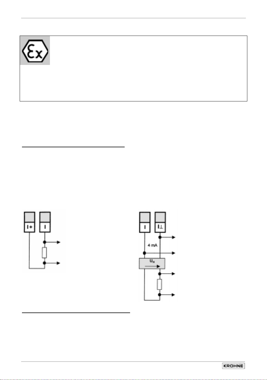
Sect. 6.2 Part C Special applications, functional checks, service, and order numbers
6.2 Interfaces
6.2.1 HART- interface
The HART
on the current output. All functions and parameters can be accessed via this interface.
The following HART® features are supported:
•
point-to-point connection
•
multidrop (up to 15 HART devices)
The burst mode is not normally used.
Further information about HART is available from the HART® Communication Foundation, of
which KROHNE is a member.
Electrical connection
HART® - active HART® - passive
d16
Important, please note!
•
Observe the directions and regulations and the electrical data specified in the
EC type test certificate.
•
In addition to the regulations for heavy-current installations (VDE 0100),
pay particular attention to the requirements specified in EN 60079-14 “Electrical
equipment in hazardous areas”.
•
Assembly, installation, commissioning and maintenance work may only be carried
out by ”personnel trained in explosion protection” !
®
interface is a smart interface, in other words a communication signal superimposed
d18
d18 z18
RI
active
to HART
or smart-converter
®
- communicator
RI
passive
to next
®
HART
- device
power supply unit
to HART
or Smart- converter
®
- communicator
Power supply unit (and section switch amplifier) must be set up accordingly if in use for HART®
operation.
58
IFC 210 E
05/2002
Page 59

Part C Special applications, functional checks, service, and order numbers Sect. 6.2
Settings and operation
Fct. Parameter Point-to-point mode Multidrop mode
1.05 Function 1 CORRECT. or 2 CORRECT. OFF
Range I
4-20 mA or I0% ≥ 4 mA I0% ≥ 4 mA
3.09 Communication HART HART
Address 0 01, 02, 03 ..... 15
(use one address at
one time only)
Operation
Current output
active or passive
passive only
For further information on setting the signal converter refer to chapters 4 and 5.
HART® operating tools / Device Description (DD)
The signal converter can be operated either via its local operator interface or by means of the
HART® communicator, which is available from KROHNE.
Operator control by means of the HART® communicator requires a device description (DD) which
we can load for you into the communicator. We can, of course, also load the DDs of all
manufacturers who have filed their DDs with the HART® Communication Foundation.
If you wish to use the signal converter in your operating tool, for example, please ask for the
description of the HART® command used so that you can address the complete signal converter
functionality via HART®.
IFC 210 E 59
05/2002
Page 60
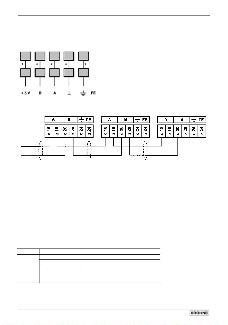
Sect. 6.2 Part C Special applications, functional checks, service, and order numbers
6.2.2 KROHNE RS 485 Interface (Option)
Electrical connection
RS 485 Interface (Option, connection at multipole connector XD)
d16 d18 d20 d22
z16 z18 z20 z22 z24
d24
internal connection
*
Address, e.g.: 001 002 003
TX+
*
*
*
TX-
The shields can be grounded as follows:
*
1) directly at both ends
or where there is risk of circulating currents,
2) directly at one end (static shielding) or
3) directly at one end and capacitive at the other end.
In the case of 2) and 3), a decrease in EMC is to be expected.
It is essential to blank off the final signal converter's electrical bus. To do this, solder up the
semicircular circuits of solder points S3 and S4 on the RS485 - PCB. For further information refer
to section 8.7.
The RS 485 protocol is available. Please contact your local KROHNE supplier / company.
Settings for use in interface operation
Fct. Parameter KROHNE RS 485 Interface
3.09 Communication KROHNE
Address 000-239
Baud rate
For further information on setting the signal converter refer to chapters 4 and 5.
•
1200
•
2400
•
4800
•
9600
•
19200
60
IFC 210 E
05/2002
Page 61

Part C Special applications, functional checks, service, and order numbers Sect. 6.3
6.3 Unsteady display and outputs
Unsteady display and outputs can occur in connection with
– high solids contents,
– non-homogeneity,
– poor blending, or
– chemical reactions still in progress in the process liquid.
If, in addition, flow is also pulsating due to the use of diaphragm or reciprocating pumps,
refer to Sect. 6.4.
Operator control of the signal converter for the new settings, see Sect. 4 and 5.
To change settings
•
Fct. 1.04 Display Flow (change display presentation of the flow)
Change setting to “Trend” to allow better assessment of display unsteadiness.
•
Fct. 1.02 Timeconstant (change time constant)
– Setting to “Only Current I”, to “All” if pulse output too unsteady.
– Set time constant to approx. “20 s”, observe unsteadiness of display and adjust time
constant if necessary.
•
Fct. 3.06 Application (adjust overload point of the A/D converter to the application).
Set to “Pulsating” on trial basis, if unsuccessful return to “Steady”.
•
Fct. 3.02 Field Frequency (change magnetic field frequency) On trial basis,
change setting to “1/2”; if unsuccessful return to previous setting, usually “1/6”.
Only practical with IFS 5000 F (DN 2.5-100 /
and IFS 4000 F (DN 10, 15, 50-100 / 1/10”, 1/2”, 2”-4”),
Consult factory where other types and meter sizes are concerned.
Important, please note!
•
Observe the directions and regulations and the electrical data specified in the
EC type test certificate.
•
In addition to the regulations for heavy-current installations (VDE 0100),
pay particular attention to the requirements specified in EN 60079-14 “Electrical
equipment in hazardous areas”.
•
Assembly, installation, commissioning and maintenance work may only be carried
out by ”personnel trained in explosion protection” !
1
/10”-4”)
IFC 210 E 61
05/2002
Page 62

Sect. 6.4 Part C Special applications, functional checks, service, and order numbers
6.4 Pulsating flow
Application
downstream of positive-displacement pumps (reciprocating or diaphragm pumps) without
pulsation dampener
Operator control of the signal converter for the new settings, see Sect. 4 and 5.
To change settings
•
Fct. 3.2 Field Frequency (change magnetic field frequency)
−
−
only practical with IFS 5000 F (DN 2.5-100 /
and IFS 4000 F (DN 10, 15, 50-100 / 1/10”, 1/2”, 2”-4”),
Please consult factory where other types and meter sizes are concerned.
−
additional measu r i n g e rrors of approx . ± 0.5% of th e m ea s u r e d v al u e m a y o c ca s i o n a l l y
•
Fct. 3.06 Application (adjust overload point of the A/D converter to the application) Change
setting to “pulsating”.
•
Fct. 1.04 Display (change display presentation of flow)
Change setting to “Trend” to allow better assessment of display unsteadiness.
•
Fct. 1.02 Timeconstant (change time constant)
−
1000
−
−
1000
With this setting, the residual ripple of the display will amount to
Important, please note!
•
Observe the directions and regulations and the electrical data specified in the
EC type test certificate.
•
In addition to the regulations for heavy-current installations (VDE 0100),
pay particular attention to the requirements specified in EN 60079-14 “Electrical
equipment in hazardous areas”.
•
Assembly, installation, commissioning and maintenance work may only be carried
out by ”personnel trained in explosion protection” !
Stroke frequency less than 80 strokes/min (at max. pump lift): do not change setting.
Stroke frequency 80 – 200 strokes/min (at max. pump lift): change setting to 1/2,
1
/10”-4”)
Please note: given stroke frequencies close to the tripping point of 80 strokes/min,
occur.
Set to “All” and time (t) in seconds.
Recommended: t [Sec] =
min. strokes / min
Example: min. number of strokes in operation = 50 strokes/minute
t [Sec] =
50 / min
= 20 Sec
approx. ±2% of the measured value. Doubling the time constant will
reduce the residual ripple by a factor of 2.
62
IFC 210 E
05/2002
Page 63

Part C Special applications, functional checks, service, and order numbers Sect. 6.5
6.5 Rapid changes in flowrate
Application
in conjunction with batching processes, fast-response control loops, etc.
Operator control of the signal converter for the new settings refer to chapters 4 and 5
To change settings
•
Fct. 1.02 Timeconstant (change time constant)
Setting to “Only Current I” and set time to 0.2 s.
•
Dynamic response with meter sizes DN 2.5-300 / 1/10”-12”
Dead time: approx. 0.06 s at 50 Hz line frequency
approx. 0.05 s at 60 Hz line frequency
Time constant: set as above, current output (mA) additionally plus 0.1 s
•
Reducing the dead time by a factor of 3 (possible by changing the magnetic field frequency)
Fct. 3.02 Flow Meter, subfunction “Field Frequency”, change to „1/2“ only practical with
IFS 5000 F (DN 2.5-100 / 1/10”-4”) and IFS 4000 F (DN 10, 15, 50-100 / 1/10”, 1/2”, 2”-4”.
Please consult factory where other types and meter sizes are concerned.
Important, please note!
•
Observe the directions and regulations and the electrical data specified in the
EC type test certificate.
•
In addition to the regulations for heavy-current installations (VDE 0100),
pay particular attention to the requirements specified in EN 60079-14 “Electrical
equipment in hazardous areas”.
•
Assembly, installation, commissioning and maintenance work may only be carried
out by ”personnel trained in explosion protection” !
IFC 210 E 63
05/2002
Page 64

Sect. 6.6 Part C Special applications, functional checks, service, and order numbers
6.6 Stable signal outputs when measuring tube empty
Output signals can be stabilized to values as for “zero” flow to prevent random output signals
when the measuring tube is empty.
- Display: 0
- Current output: 0 or 4 mA, see setting in Fct. 1.05
- Pulse output: no pulses (= 0 Hz), see setting in Fct. 1.06
Precondition:
- Homogeneous liquid products, free of solids and gasses an do not tend to
electrical or catalytic reactions.
LA / S3 Empty Tube indication LA / S2 Empty Tube stabilization
LA / S3 actively detects an empty
measuring tube and switches
outputs and display to “0“ flow.
When the measuring tube is
empty, resistance between the
electrodes becomes very high.
A low current flows through the
-15 V at the one electrode (the
other is connected to 0 V, chassis)
via the high-resistance resistor and
overdrives the instrumentation
amplifier and then the A/D
converter. This overdriving is
evaluated.
Important, please note!
•
Observe the directions and regulations and the electrical data specified in the
EC type test certificate.
•
In addition to the regulations for heavy-current installations (VDE 0100),
pay particular attention to the requirements specified in EN 60079-14 “Electrical
equipment in hazardous areas”.
•
Assembly, installation, commissioning and maintenance work may only be carried
out by ”personnel trained in explosion protection” !
- electrical conductivity of product: ≥ 200 µS/cm,
≥ 500 µS/cm for meter sizes DN 2.5 – 15 and
1
/10” – 1/2”
- Signal cable length ≤ 10m and vibration free with signal converter
steady display at “0“ flow
LA / S2 should be used when
problems are encountered with LA /
S3, e.g. due to electrolysis effects.
Display is then particularly
unsteady.
At “0“ flow, the electrodes are
connected to 0 V (chassis) via highresistance resistors.
LA / S4 electrode cleaning
and Empty Tube stabilization
LA / S4 prevents any deposits of
high-resistance layers on the
electrodes (e.g. fat from very
creamy milk) and effects
stabilization similar to the LA / S2.
For this purpose, the electrodes
are connected to –15 V via highresistance resistors.
- 15 V
To join the “semicircles“ of the two
soldering points S1 and S4,
see under ”Point 5“.
Under Fct. 3.06 Applications, set
“yes“ for empty pipe.
To join the “semicircles“ of the two
soldering points S1 and S2,
see under ”Point 5“.
Possibly reset low-flow cutoff
(SMU), see under Point 8
0 V
64
IFC 210 E
To join the “semicircles“ of the two
soldering points S3 and S4,
see under ”Point 5“.
Possibly reset low-flow cutoff
(SMU), see under Point 8
05/2002
Page 65

Part C Special applications, functional checks, service, and order numbers Sect. 6.6
Changes on amplifier PCB, see Fig. in Sect. 8.7.
Always switch off power source before starting work!
Please refer to the Figure in Sect. 8.1.
1) Detach 4 screws (S1) from the front side.
2) Pull the plug-in module out of the subrack.
3) Detach 4 recessed-head screws (S3) on the rear side and remove the imprinted rear panel
from the plug-in unit.
4) Carefully pull the now visible rear panel with mounted pc boards out of the plug-in unit.
5) On the back of the amplifier board, join the “semicircles“ of 2 points with tin-lead solder,
depending on activation of the desired function, see Table and Figures in Sect. 6.6.
Previous to that, carefully scrape off the protective varnish at the selected soldering points
............. Be careful not to damage circuit-board conductors.
6) Assemble in the reverse order, Points 4) – 1).
7) Power the unit.
8) For LA / S2 (empty tube stabilization) and LA / S4 (electrode cleaning and empty tube
stabilization), check the setting of the low-flow cutoff SMU, Fct. 1.03, and reset if necessary:
L.F.Cutoff switched on, range: Full scale range Q
Cutoff ...... values
100%
... OFF ... ... ON ...
> 3 m/s > 10 ft/s > 2 % 1 %
1 – 3 m/s 3 -10 ft/s > 6 % 4 %
< 1 m/s < 3 ft/s > 10 % 8 %
IFC 210 E 65
05/2002
Page 66

Sect. 7.1 Part C Special applications, functional checks, service, and order numbers
)XQFWLRQDOFKHFNV
7
7.1 Zero check
Set
zero flow
in the pipeline, but make sure that the
•
measuring tube
completely filled
is
with fluid.
•
Switch on the system and wait 15 minutes.
•
Press the following keys for zero measurement:
Key Display Description
→
Fct. 1.00 Operation
2x ↑
→
2x ↑
→
↑
↵
Store No
measuring mode.
↑
↵
(2x) 3x ↵
If “Yes” set under Fct. 3.04 ENTR Y CODE, key in
9-keystroke CODE 1 now: → → → ↵ ↵ ↵ ↑ ↑ ↑
Fct. 3.00 Installation
Fct. 3.01 Language
Fct. 3.03 Zero Point
back
enquire
0.00 - - - - - / - - - Zero measurement in progress, duration approx. 50 seconds.
When flow > 0 WARNING notice appears, confirm with ↵ key.
If new value not to be stored, press ↵
Store Yes
Fct. 3.03 Zero Point Store new zero value.
- - - - - - - - - - - - / - - - Measuring mode with new zero.
key (3x) 4x = return to
7.2 Test of measuring range Q
•
For this test a measured value can be simulated in the range of -110 to +110 percent of Q
(full-scale range set, see Fct. 1.01 Full Scale).
•
Switch on the system..
•
Press the following keys for this test::
Key Display Description
→
Fct. 1.00 Operation
↑
→
→
↑
↵
corresponding values.
± 10 %
↑
± 100 %
± 110 %
↵
(2x) 3x ↵
If “Yes” set under Fct. 3.04 ENTR Y CODE, key in
9-keystroke CODE 1 now: → → → ↵ ↵ ↵ ↑ ↑ ↑
Fct. 2.00 Test
Fct. 2.01 Test Q
sure no
sure yes
0 % Current, pulse and status indication outputs indicate the
± 50 %
Fct. 2.01 Test Q End of test, actual measured values again present at outputs.
- - - - - - - - - - - - / - - - Measuring mode
Select using ↑ or ↓ key
100%
66
IFC 210 E
05/2002
Page 67

Part C Special applications, functional checks, service, and order numbers Sect. 7.3
7.3 Hardware information and error status, Fct. 2.02
•
Before consulting factory about errors or flow measurement problems, please invoke Fct.
2.02 Hardwareinfo (hardware information).
•
An 8-character and a 10-character status code are stored under this function in
each of 3 (4) “windows”. These 6 (8) status codes allow rapid and simple diagnosis of your
compact flowmeter.
•
Switch on system.
•
Press the following keys for display of the status codes:
Key Display Description
Fct. 1.00 Operation
↑
→
↑
→
- - - - - - - - -
↵
- - - - - - - - -
↵
- - - - - - - - -
↵
- - - - - - - - - Option installed)
↵
(2x) 3x ↵
Fct. 2.00 Test
Fct. 2.01 Test Q
Fct. 2.02 Hardware Information
→
Modul ADW
→
Modul EA
→
Modul Anzeige
→
Modul RS
Fct. 2.02 Hardware Information Terminate hardware information
- - - - - - - - - - - - - / - - - Measuring mode
PLEASE NOTE DOWN ALL 6 (8) STATUS CODES !
-.- - - - -.- -
-.- - - - -.- -
-.- - - - -.- -
-.- - - - -.- -
If you need to return your flowmeter to KROHNE, please refer to last
but one page of these Instructions !
If “Yes” set under Fct. 3.04 ENTR Y CODE, key in
9-keystroke CODE 1 now: → → → ↵ ↵ ↵ ↑ ↑ ↑
1st window
2nd window
3rd wind o w 3A47F01DB1
4rd window
Sample status code
3.25105.02
(only provided if “computer interface”
( 8-character code, 1st line)
(10-character code, 2nd line)
7.4 Faults and symptons during start-up and process flow measurement
•
Most faults and symptoms occurring with the flowmeters can be eliminated
with the aid of the following tables.
•
For greater clarity, faults and symptoms in the tables are divided into various groups.
Groups: D Display
I Current output
P Pulse output
B Status output or control input
D / I / P / B Display, current output, pulse output,
Safety notice
Some of the following measurements are carried out when the system is in the switched on
condition. Exercise caution when handling measuring leads in the vicinity of power connections −
electric shock hazard and risk of short-circuiting!
CAUTION!
The following applies to primary heads in hazardous areas:
Installation, electrical connection, commissioning and maintenance work may only
be carried out by persons who have been trained for work in hazardous areas and
are authorized to do so.
binary outputs/inputs
Before contacting KROHNE Service, please read through the
following tables. THANK YOU !
IFC 210 E 67
05/2002
Page 68

Sect. 7.4 Part C Special applications, functional checks, service, and order numbers
Gruppe D Display shows . . . Cause Remedial action
D 1 Line Int. Power failure.
D 2 I Overrange Current output overranged.
D 3 P Overrange Pulse output overranged.
D 4 Totalizer Counts lost
D 5 ADC Analog/digital converter
D 6 Fatal Error Fatal-Error, all outputs set to
D 7 Startup
cyclic flashing
D 8 Pipe empty The measuring tube is empty.
D 9 Unsteady display – Process product
Group I Fault / Symptom Cause Remedial action
I 1 Receiver instrument
indicates “0”.
Note:
no counting during
power failure.
(Flow > measuring range)
Note:
totalizer deviation
possible
(Flow > I Max)
(overflow, data error)
overranged.
“min.” values.
Hardware fault,
Watchdog activated.
This message appears only when
Option ”empty pipe
the
identifier“
function is switched on under Fct.
3.06 Application, submenu
“empty pipe“.
– Pulsating flow
– Time constant too low or
Power supply OFF Power supply ON D 10 No display
Check power fuse F5. Replace if defective
Incorrect connection/polarity Connect properly, see Sect. 2.4.
Receiver instrument or
current output defective.
Current output disabled,
see Fct. 1.05
Short-circuit between current
output and pulse output.
External voltage source defective Check power lines and/or external
is built in and when the
conductivity too low,
particles/air inclusions too large
or inhomogeneous
switched off.
Delete error message in
RESET/QUIT. menu. Reset
totalizer(s) if need be.
Check instrument parameters and
correct if necessary. Error message
deleted automatically after cause
has been eliminated.
Check instrument parameters,
correct if necessary, and reset
totalizer(s). Error message deleted
automatically after cause has been
eliminated.
Delete error message in
RESET/QUIT. menu.
Error message deleted
automatically after cause has been
eliminated.
Replace signal converter
(see Sect. 8.3) or contact KROHNE
Service, having first noted down
hardware information and error
status, see Fct. 2.02.
Replace signal converter
(see Sect. 8.3) or contact
KROHNE Service.
Fill the pipe.
Increase time constant,
see Fct. 1.02, or switch on.
(see Sect. 8.2).
Check output (see Sect. 7.2) with
new milliammeter: Test ok
check connection cables and
receiver instrument, replace if
necessary. Test unsuccessfully
current output defective. Replace
signal converter (see Sect. 8.3) or
contact KROHNE Service
Activate under Fct. 1.05.
Check connection and cables,
see Sect. 2.4. Voltage between
I+ and I⊥ (connecting block XC
Pins d16 and z18), approx. 24 V.
Switch off device, eliminate shortcircuit, and switch device on again.
voltage source, and replace if
necessary.
,
,
68
IFC 210 E
05/2002
Page 69

Part C Special applications, functional checks, service, and order numbers Sect. 7.4
Group I Fault / Symptom Cause Remedial action
I 2 Unsteady display – Process product conductivity
Group P Fault / Symptom Cause Remedial action
P 1 Totalizer connected but does
not count any pulses
P 2 Unsteady pulse rate – Process product conductivity
P 3 Pulse rate too high or too
low.
Group B
B 1 No function Faulty connection Connect properly, see Sect. 2.4.
Output/input defective Replace electronics unit of signal
External or internal voltage source
Receiver instruments faulty Check connection, if necessary
Function setting faulty Correct function settings.
Gruppe D/I /P/ B
D / I / P / B 1 Unsteady display and outputs – Process product conductivity
no function of outputs
too low, particles/air inclusions
too large or inhomogeneous
– Pulsating flow
– Time constant too low or
switched off.
Incorrect connection/polarity Connect properly, see Sect. 2.4.
Totalizer or external voltage
source defective.
Current output is external
voltage source, short circuit
or current / pulse output defective
Pulse output is deactivated,
see Fct. 1.06.
too low, particles/air inclusions
too large or inhomogeneous
– Pulsating flow
– Time constant too low or
activated only for current output I
Incorrect setting for pulse output. Change setting under Fct. 1.06.
not supplying voltage
too low, particles/air inclusions
too large or inhomogeneous
– Pulsating flow
– Time constant too low
Power supply OFF Power supply ON D / I / P / B 2 No display and
Check power fuse F5. Replace if defective, see Sect. 8.2.
Increase time constant,
see Fct. 1.02
Check output (see Sect. 7.2) with
new totalizer: Test ok
check connection cables and
previous totalizers and external
voltage source, and replace if
necessary. Test faulty
pulse output defective, replace
signal converter (see Sect. 8.3) or
contact KROHNE Service.
Check connection and cables,
see Sect. 2.4. Voltage between
I+ and I⊥ (connecting block XC
Pins d16 and z18), approx. 24 V.
Switch off device, eliminate shortcircuit, and switch device on again.
If no function, then current or pulse
output defective. Replace signal
converter (see Sect. 8.3) or contact
KROHNE Service.
Switch on under Fct. 1.06.
Increase or switch on time
constant, under Fct. 1.02 or switch
on if necessary.
converter, see Sect. 8.3
Check voltage source, rectify any
short-circuit or replace defective
voltage source.
replace receiver instruments.
Increase time constant,
under Fct. 1.02
,
,
IFC 210 E 69
05/2002
Page 70
Sect. 7.5 Part C Special applications, functional checks, service, and order numbers
7.5 Checking the primary head
This method describes the testing of the primary head and its interconnecting cables at the
installation location of the signal converter.
Always switch off power source before starting work on the subrack connections.
Required measuring instruments and tools
•
Ohmmeter with at least 6 V measuring voltage range
•
or AC voltage/resistance bridge
•
Note:
an AC voltage/resistance bridge. The measured resistance also heavily
depends on the electrical conductivity of the process liquid.
Preparations
•
Switch off the power supply.
•
Pull plug-in unit out of the subrack.
•
Fill the measuring tube of the flowmeter completely with process liquid.
•
Please note:
for connections which are occupied (used).
The Nos. in brackets ( _ _ _ ) identify the power terminals at the primary head.
Action
Resistance measurements at the
XA
, electrical connection to primary head:
signalling cable
cable
1
2
3 If lower
4
CAUTION!
The following applies to primary heads in hazardous areas:
Installation, electrical connection, commissioning and maintenance work may only
be carried out by persons who have been trained for work in hazardous areas and
are authorized to do so.
accurate measurements in the electrode area can only be obtained with
the following measurements must only be carried out
plug connector
(max. 5-pin) and
Measure resistance of cables between
d30
Pins
Measure resistance of cables between
Pins
(1 and 7) or Pins
(1 and 8)
Measure resistance of cables between
Pins
between Pins
Always
on Pin
When signal cable B (type BTS/
bootstrap) is used:
measure resistance between
the following lines:
Pins
Pins
Pins d6 and
Pins z6 and d6 (2 and 20),
Pins
d32
and
d8/z8
d8/z8 a
use the same measuring lead
d8/z8
d8/z8
d8/z8
z10
and
(7 and 8)
d30
and
d8/z8
z6
nd
d8/z8 a
(1)!
and d6 (1 and 20),
d10
and
d10
(20 and 30),
d10
(3 and 30).
field current
d32
and
(1 and 2), and also
nd
(1 and 30),
z10
(1 and 3).
Typical result Incorrect result for 1 – 3 =
30 – 170 Ω
> 20 M Ω
1 kΩ – 1 MΩ
(see Note above).
Both values should
be approx. equal.
> 20 M Ω
defective primary head,
return to factory for repair,
refer to last-but-one page !
If lower
, interwinding fault.
If higher
If lower
to PE or FE.
measurement; if still too low, short-circuit in
electrode wires.
If higher
electrodes contaminated.
If values differ considerably
electrode wires or electrodes contaminated.
If lower,
Check connection cables, replace signal
cable if necessary.
, wire break.
, interwinding fault
, drain measuring tube and repeat
, break in electrode wires or
, line fault.
, break in
70
IFC 210 E
05/2002
Page 71

Part C Special applications, functional checks, service, and order numbers Sect. 7.6
(
7.6 Test of signal converter using GS 8 A simulator (option)
GS 8 A operating elements and accessories
Electrical connection
CAUTION!
The following applies to primary heads in hazardous areas:
Installation, electrical connection, commissioning and maintenance work may only
be carried out by persons who have been trained for work in hazardous areas and
are authorized to do so.
D Switch,
Flow direction
H Socket for H1
plug On cable M
H1 Plug of cable M
L Power supply ON
M Cable between
GS 8A and IFC 210 E
signal converter
P Potentiometer "zero point"
Y Switch, Measuring ranges
a) Switch off power supply
before starting work !
b) Unscrew the 4 recessed head screws (S1)
on the front plate (see Sect. 8.1, Fig.).
c) Carefully pull off plug-in unit from subassembly
support.
d) The electrical connection is on the X1 and X2 connectors at
the rear hand side of the IFC 210 E signal converter as
shown in connection diagram with cable M.
IFC 210 E 71
05/2002
Power supply
connection
mA meter, accuracy class 0.1,
A
< 500 Ohm, range 4-20 mA
R
i
Electronic frequency counter,
input resistance approx. 1 k Ohm,
range 0-1 kHz,
time basis min. 1 second,
see connection diagrams
in Sect. 2.5.
Electrical connection
of mA meter and
electronic frequency
counter
see Sect. 2.5).
Page 72

Sect. 7.6 Part C Special applications, functional checks, service, and order numbers
Check of setpoint display
1) Switch on power supply, allow at least 15 minutes’ warm-up time.
2) Set switch D (front panel of GS 8A) to “0” position.
3) Adjust zero to 0 or 4 mA with the 10-turn potentiometer P (front panel of GS 8A),
depending on setting in Fct. 1.05, deviation < ±10 µA.
4) Calculate position of switch Y and displayed setpoints ”I“ and ”f“:
4.1) X =
Q
100%
GK × DN2
× K
Q
full-scale range (100%) in volumetric unit V per unit time t
100%
GK primary constant, see instrument nameplate
DN meter size DN im mm, not inches, see instrument nameplate
t time in seconds (Sec), minutes (min) or hours (hr)
V volumetric unit
K
constant, according to following table
:
t Sec min hr
V
Liter 25 464 424.4 7.074
m3 25 464 800 424 413 7 074
US-Gallonen 96 396 1 607 26.78
4.2) Determine position of switch Y:
which comes closest to factor X and meets condition Y ≤ X.
4.3) Calculate setpoint reading ”I“ for current output:
I
I
4.4) Calculate setpoint reading ”f“ for pulse output:
P
Use table (front panel GS 8A) to determine value Y,
I = I0% + (I
0%
100%
f = × P
100%
Y
X
- I0%) in mA
100%
current (0/4mA) at 0% flowrate
current (20mA) at 100% flowrate
Y
X
100%
in Hz
pulses per second (Hz)
at 100% flowrate
5) Set switch D (front panel GS 8A) to position “+“ or “-“ (forward/ reverse flow).
6) Set switch Y (front panel GS 8A) to the value determined by the method described above.
7) Check setpoint readings I and f, see points 4.3 and 4.4 above.
8) Deviation < 1.5% of setpoint. If greater, replace signal converter, see Sect. 8.3.
9) Test of linearity: set lower Y values, readings will drop in proportion
to the calculated Y values.
10) Switch off power supply after completing the test.
11) Disconnect the GS 8A.
12) Reassemble in reverse order, see points e) – b) under “electrical connection”,
see illustration in Sect. 8.1.
13) The system is ready for operation after the power supply has been switched on.
Example: see overleaf
72
IFC 210 E
05/2002
Page 73

Part C Special applications, functional checks, service, and order numbers Sect. 7.6
Example
Full-scale range Q
Meter size DN = 80 mm = 3” (Fct. 3.02)
Current at Q0% I0% = 4 mA
Q
Pulses at Q
Primary head constant GK = 3.571 (s. Geräteschild)
Constant (V in m
I
100%
P
100%
3
)
= 200 m3/hr (Fct. 1.01)
100%
(Fct. 1.05)
= 20 mA
100%
= 200 Pulse/hr (Fct. 1.06)
100%
}
(t in hr) K = 7074 (see Table)
(DN in mm)
Calculation of „X“
Q
X =
100%
GK x DN2
and position of „Y“
x K 200 x 7074
=
3.571 x 80 x 80
= 61.905
Y = 40, position of switch Y, see front panel GS 8A
(comes closest to X value and is smaller than X).
Calculation of setpoint readings I and f
I = I0% + (I
Y
X
- I0%) = 4 mA +
100%
40
61.905
(20mA - 4mA) = 14.3mA
Deviations are permissible between 14.1 and 14.6 mA (equivalent to ± 1.5 %)
Y
f = x P
X
100%
=
61.905
40
x 200 pulses/hr = 129.2 pulses/hr
Deviations are permissible between 127.3 and 131.1 pulses/hr (equivalent to ± 1.5 %)
If you need to return your flowmeter to KROHNE,
please refer to last but one page of these Instructions !
IFC 210 E 73
05/2002
Page 74

Sect. 8.1 Part C Special applications, functional checks, service, and order numbers
8 6HUYLFH
8.1 Illustrations used for service work
Fig. 1 Front view
Fig. 2 Back view
Fig. 3 Marking of terminal strips
(on rear side of plug-in unit)
RS485- interface (Option)
74
IFC 210 E
Applies to EEx version only
05/2002
Page 75

Part C Special applications, functional checks, service, and order numbers Sect. 8.2
8.2 Replacement of power supply fuse
CAUTION!
The following applies to primary heads in hazardous areas:
Installation, electrical connection, commissioning and maintenance work may only
be carried out by persons who have been trained for work in hazardous areas and
are authorized to do so.
Switch off power supply before starting work
Refer to Sect. 8.1 for Figs. 1 and 2.
1) Unscrew the 4 recessed head screws (S1), on the front (Fig. 1).
2) Carefully remove the plug-in unit from the subassembly support.
3) Detach 4 recessed-head screws (S3) on the rear side of the plug-in unit (Fig. 2).
4) Carefully remove the electronics insert from the plug-in unit.
5) Change power fuse F5 on the “power supply unit“ board (Fig. in Sect. 8.4). For values and
order no., refer to Sect. 9.
6) Reassemble in reverse order, points 4) - 1) above.
8.3 Replacement of electronics unit of signal converter
Refer to Sect. 8.1 for Figs. 1 and 2.
1) Unscrew the 4 recessed head screws (S1), on the front (Fig. 1).
2) Carefully remove the plug-in unit from the subassembly support.
3) Detach 4 recessed-head screws (S3) on the rear side of the plug-in unit (Fig. 2).
4) Carefully remove the electronics insert from the plug-in unit.
5) Carefully transpose DATAPROM (IC 4) on conductor side the amplifier-PCB (see Fig. in Sect.
8.4) from the “old” and the “new” electronic unit . Watch the position of the IC 4 when putting it
on.
6) Check the power supply and fuse F5 on the new electronic unit.
7) Reassemble in reverse order, points 4) - 1) above.
CAUTION!
The following applies to primary heads in hazardous areas:
Installation, electrical connection, commissioning and maintenance work may only
be carried out by persons who have been trained for work in hazardous areas and
are authorized to do so.
IFC 210 E 75
05/2002
Page 76
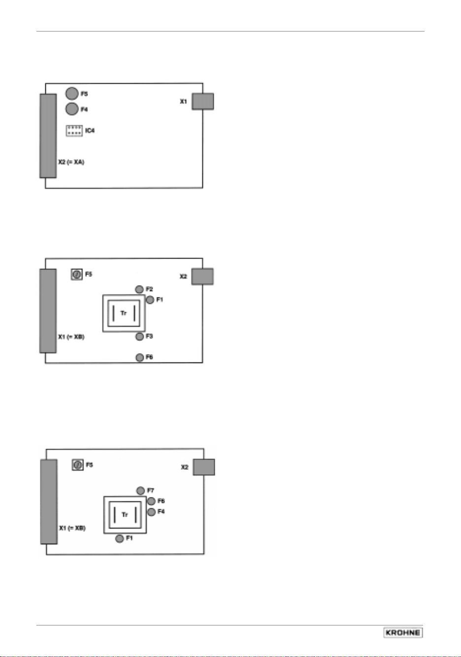
Sect. 8.4 Part C Special applications, functional checks, service, and order numbers
8.4 Illustrations of the PCBs
A) Amplifier PCB
B) Power supply PCB
AC versions (100 – 230 V AC)
C) Power supply PCB
AC-Version (24 V AC/DC)
X1 Plug for internal connections
NOTE: not provided for
EEx version, which instead has the
additional GTEX board
X2 (= XA) Push-on terminal strip XA, external
connection via socket connector to
DIN 41 612, Style F, 32-pin
F4 + F5 Field current fuse, 160 mAF, miniature fuse
TR 5
(for IFC 210 E-EEx: if necessary, adjust to
max. permissible fuse nominal value for the
primary head)
IC 4 DATAPROM, stores all operating data, see
Sect. 8.3 and 8.4 (on conductor side,
see separate Figure)
X1 (= XB) Push-on terminal strip XB, external connection
via socket connector to DIN 41 612, Style F,
X2 Plug for internal connections
Tr Transformer
32-pin
F5 Power fuse, 800 mAT,
(5 x 20 G, switching capacity 1500 A)
For order No. see Sect. 9
Sundry miniature fuses TR 5,
For order No. see Sect. 9
F1 Optocoupler, fuse 50 mAT
F4 5V/15V fuse, 630 mAT
F6 Current output, fuse 200 mAT
F7 Field current supply, fuse 630 mAT
X1 (= XB) Push-on terminal strip XB, external connection
via socket connector to DIN 41 612, Style F,
X2 Plug for internal connections
Tr Transformer
32-pin
F5 Power fuse, 1.6 AT,
(5 x 20 G, switching capacity 1500 A)
for order No. see Sect. 9
Sundry miniature fuses TR 5,
for order No. see Sect. 9
F1 Current output, fuse 200 mAT
F2 Field current supply, fuse 630 mAT
F3 5V/15V fuse, 630 mAT
F6 Optocoupler, fuse 100 mAT
76
IFC 210 E
05/2002
Page 77

Part C Special applications, functional checks, service, and order numbers Sect. 8.4
D) Amplifier PCB (conductor side)
X2 (= XA) Plug connector XA, external connection via
socket connector to DIN 41 612, Style F, 32-pin
IC 4 DATAPROM, stores all operating data, see Sect. 8.4
S1 – S4 Soldering jumpers for various functions, see Sect. 6.3
IFC 210 E 77
05/2002
Page 78
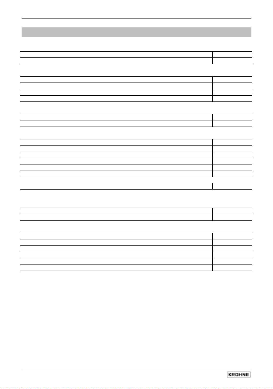
Sect. 9 Part C Special applications, functional checks, service, and order numbers
2UGHUQXPEHUV
9
Electronic unit, complete
100 – 230 V AC Standard (not EEx / not RS 485) 2.12233.01.00
24 V AC / DC 2.12233.02.00
PCBs, single
PCB – Power supply unit for 100 – 230 V AC 2.11671.01.00
24 V AC / DC 2.12070.01.00
PCB – Amplifier Standard (not EEx) 2.11556.01.00
PCB – I / O (Inputs / Outputs) 2.11615.01.00
Power fuses F5 (5 x 20 G / switching capacity 1500 A)
800 mA T (100 – 230 V AC) 5.08085.00.00
1.6 A T (24 V AC / DC) 5.07823.00.00
miniature fuses TR 5
50 mA T 5.07576.00.00
100 mA T 5.07561.00.00
160 mA F 5.10283.00.00
200 mA T 5.07563.00.00
500 mA T 5.07586.00.00
630 mA T 5.08019.00.00
19” subrack with guide rails, preassembled On request
19” subrack, fully assembled
with built-in IFC 210 E, socket connectors with solder terminals
100 – 230 V AC On request
24 V AC / DC On request
Blanking plates
2 TE 3.06660.00
3 TE 3.06738.00
5 TE 3.06739.00
8 TE 3.06740.00
14 TE 3.06741.00
21 TE 3.06590.00
78
IFC 210 E
05/2002
Page 79

Part D Technical Data, Measuring Principle and Block Diagram Sect. 10.1
7HFKQLFDOGDWD
10
10.1 IFC 210 E signal converter
5DQJHRIDSSOLFDWLRQ
Flow measurement of liquid products
0RGHRIRSHUDWLRQDQGV\VWHPVWUXFWXUH
Measurement principle Faraday`s laws of induction
Modularity Measuring system consisting of
signal converter and separate primary head
Versions – signal converter
IFC 210 E (Standard) - Standard version with large graphic LC display and
integrated HART
®
interface
IFC 210 E / RS 485 (Option) - same as standard version, but additionally with
RS 485 interface
IFC 210 E / _ / EEx (Option) - same as standard version, for operation with
primary heads installed in hazardous areas
Interface module (Option) - RS 485 / Profibus PA (in preparation)
Versions – primary head
Refer to Technical Data in separate Installation
Instructions
,QSXW
Measured variable Volumetric flow rate
(electrode voltage from primary head)
Measuring range Dependent on meter size of primary head
see also Table in Sect. 10.2
Full-scale range 6 Liter/h to 86 860 m
flow velocity v = 0.3 to 12 m/s
Selectable units m
3
/h, Liter/s, US Gallons/min or freely selectable
3
/h, corresponding
unit, e.g. Liter/day
2XWSXW
Output/input signal Current- Pulse- Status- Control-
Output output output input
Operation active/
passive
Failure signal (error) 22 mA,
active/
passive Passive
passive
– yes –
and others
Load impedance
max. 800 Ω
– – –
Low flow Yes – yes –
F/R mode Yes yes – –
Other functions
detailed technical data (see below)
Yes
yes
yes
yes
IFC 210 E 79
05/2002
Page 80

Sect. 10.1 Part D Technical Data, Measuring Principle and Block Diagram
Current output
Function - all operating data settable
- galvanically isolated from all output and
input circuits
- for active or passive mode
Current: fixed ranges: 0 - 20 mA and 4 - 20 mA
variable ranges: for Q = 0% I
for Q = 100% I
for Q > 100% I
Active mode
max. 800 Ω load
= 0 - 16mA
0%
= 4 - 20mA
100%
= 22mA
max
adjustable
in 1mA
}
increments
Error identification 0 / 22 mA and variable
Forward/reverse flow measurment direction identified via status output
Pulse output
Function - all operating data settable
- galvanically isolated from current output and
all input circuits
- digital pulse division, interpulse period non-uniform,
- therefore if frequency and cycle meters connected
allow for minimum counting interval::
1000
gate time, totalizer≥
P
100%
[Hz]
Activ mode connection: electronic totalizers
Passive mode connection: electronic or electromechanical totalizers
Electrical data see connection diagrams in Sect. 2.5
Pulse width automatic: pulse duty cycle 1:1,
max 10 000 pulses/Sec = 10 kHz
variable: 10 ms - 1 s
1
P
[pulses/s] = f
100%
max
[Hz] =
2x pulse width
Forward/reverse flow measurement flow direction identified via status output
Status output (passive)
Function settable as measuring range identification for BA
mode, automatic range change,
Overrange, Low Flow Cutoff, indicator for flow
direction, errors or trip point, change-over contact
(Statusoutput B2 inverse to B1)
Electrical data see connection diagrams in Sect. 2.5
Control input (passive)
Function - settable for range change, totalizer reset, error reset,
set outputs to min. values or hold actual output values
- initiate function by low or high control signals
Control signals U
: 24 V AC 32 V DC (any polarity)
max
low: ≤ 1,4 V ≤ 2 V
high: ≥ 3 V ≥ 4 V
Time constant 0.2 - 99.9 s, adjustable in increments of 0.1 second
Low-flow cutoff Cutoff on value: 1 - 19 %
Cutoff on value: 2 - 20 %
of Q
}
in 1% increments
, adjustable
100%
80
IFC 210 E
05/2002
Page 81

Part D Technical Data, Measuring Principle and Block Diagram Sect. 10.1
PHDVXULQJDFFXUDF\
Display, digital values, pulse output
F maximum error in % of measured value (not typical values)
v Flow velocity in m/s and ft/s
Reference conditions similar to EN 29 104
Product water at 10 – 30°C/ 50 – 86°F
Electrical conductivity > 300 mS/cm
Power supply (rated voltage) U
(± 2%)
N
Ambient temperature 20 – 22°C
Warm-up time 60 min
Max. calibration equipment error
Inlet/outlet runs
10 × smaller than F
10 × DN / 2 × DN (DN = meter size)
Primary head properly grounded and centered
Calibrated on EN 17025 accredit to calibration equipment in direct volumetric comparsion.
* IFS 6000 F (DN 2.5 – 4 and 1/10’’ – 1/6’’)
additional error ± 0,3% of MV
Type/Meter size Maximum error in % of measured value (MV) ... Curve
DN mm inch
DN 2.5 – 6* 1/10’’ – 1/4’’ *
v ≥ 1 m/s / ≥ 3 ft/s
≤ ± 0.5% of MV ≤ ± (0.4% of MV + 1 mm/s)
≥ DN 10 ≥ 3/8’’ ≤ ± 0.3% of MV ≤ ± (0.2% of MV + 1 mm/s)
Current output
same error limits as above, additionally ± 10 µA
v < 1 m/s
≤ ± (0.4% of MV + 0.04 inch/s
≤ ±(0.2% of MV + 0.04 inch/s)
B
A
Reproducibility and
repeatability 0,1% of MV, minimum 1 mm/s / 0.04 inch/s at constant flow
External influences typical values
maximum values
Ambient temperature
Pulse output 0,003% of MV (1) 0,01 % of MV (1)
Current output 0,01 % of MV (1) 0,025% of MV (1)
Power supply < 0,02 % of MV 0,05 % of MV. at 10% variation
per 1 K / 1.8° F
}
temperature variation
Load < 0,01 % of MV 0,02 % of MV at max. permissible
load, see Sect. 10.1
and 2.5
(1) All KROHNE signal converters undergo burn-in tests, duration minimum 20 hours at varying ambient temperatures
– 20 to + 60°C/– 4 to + 140°F. The tests are controlled by computers.
IFC 210 E 81
05/2002
Page 82

Sect. 10.1 Part D Technical Data, Measuring Principle and Block Diagram
)LHOGVHUYLFHFRQGLWLRQV
6.1 Installation conditions
Signal converter
For further information, refer to Sect. 1.1 and 10.3
Primary head
6.2 Ambient conditions
Signal converter
Ambient temperature -25 to +60 °C (EEx: -20 to +55 °C)
Storage temperature -25 to +60 °C
Protection category (IEC 529/EN 60 529) IP 20
Electromagnetic compatibility EMC to EN 61326-1 (1997) and A1 (1998), and
NAMUR Standard NE 21
Primary head
6.3 Process product conditions
Electrical conductivity
Other product conditions Refer to Installation Instructions for the primary head
&RQVWUXFWLRQ
Signal converter 19” plug-in unit to DIN 41 494,
28 modules wide, 3 upright modules high
Dimensions
approx. 1.3 kgs
Weight
Material
Electrical connection
Terminal strips XA: Primary head, see Sect. 1.3.5
XB: Power supply, see Sect. 1.3.5
XC: Inputs and outputs, see Sect. 2.5
XD: Option, RS 485 interface, see Sect. 6.2.2
Styles
Primary head Refer to separate Installation Instructions
Aluminium section, stainless steel and aluminium
Installation in 19” rack, dust-free and dry,
Refer to separate Installation Instructions
Refer to separate Installation Instructions
Refer to Sect. 10.3
≥ 5 µS/cm
≥ 20 µS/cm for demineralized cold water
sheet, partially polyester-coated
•
32-pin, contact surface gold-plated
•
plug connectors Style F to DIN 41 612
•
socket connectors Style F to DIN 41 612 and
transverse soldered connections (included)
•
Special versions on request
82
IFC 210 E
05/2002
Page 83

Part D Technical Data, Measuring Principle and Block Diagram Sect. 10.1
'LVSOD\DQG8VHU,QWHUIDFH
Local display
High-contrast, illuminated graphic LC display,
temperature-compensated, very good readability,
128x64 dots, view surface approx. 69 mm x 36 mm
Display function current flow, forward, reverse and sum totalizers or
bar graph with status messages
Units: actual flow m
3
/hr , Liter/Sec, US gallons/min. or user-defined unit
such as Liter/day or US MGal/day
totalizer m
3
, Liter or US gallons or user-defined unit such as
hectolitres or US MGal
(adjustable counting time up to overflow)
Language of clear texts German, English, French, other languages on request
Operation
by 5 keys: ← → ↵ ↑ ↓
3RZHUVXSSO\
Field current supply
Type bipolar, pulsed DC field for all KROHNE primary
heads, galvanically isolated from all output and input
circuits
Terminals Plug connector XA, pins z30 and z32
(primary head: terminals 7 and 8)
Current/voltage ± 0.125 A (± 5%) / max. 40V
Clock frequency
1
/36 to 1/2 of line frequency,
adjustable acc. to calibration data of primary head
signal converter AC-version AC/DC version
standard optional
Voltage range (without change-over) 100 - 230 V AC 24 V AC 24 V DC
Tolerance range 85 - 255 V AC 20.4 - 26.4 V AC 18 - 31.2 V DC
Frequency 48 - 63 Hz 48 - 63 Hz
Power input 11 VA, 11 VA, 11 W
(incl. primary head) typical typical typical
(max. 14 VA) (max. 14 VA) (max. 14 VA)
When connected to a functional extra-low voltage,
safety separation (PELV) must be ensured.
24 V AC/DC
,
IFC 210 E 83
05/2002
Page 84

Sect. 10.1 Part D Technical Data, Measuring Principle and Block Diagram
&HUWLILFDWHVDQG$SSURYDOV
Signal converter [EEx ib] IIC / II(2)G
PTB 00 ATEX 2026X
Primary head see separate Installation Instructions
2UGHULQIRUPDWLRQ
Versions
Signal converter
see Sect. 10.1, part 2
„Mode of operation and system structure“
Versions Primary head Refer to Technical Data in separate Installation
Instructions
([WHUQDO6WDQGDUGVDQG'LUHFWLYHV
see Page 5
84
IFC 210 E
05/2002
Page 85

Part D Technical Data, Measuring Principle and Block Diagram Sect. 10.2
10.2 Full-scale range Q
100%
Full-scale range Q
100%
Flow rate Q = 100% 6 liter/hr up to 86 860 m3/hr, (0.03 – 401 000 US Gal/min),
adjustable required,
equivalent flow velocity 0.3 - 12 m/s (1 - 40 ft/s)
Unit m3/hr, Liter/Sec, US gallons/min or user-defined unit,
e.g. Liter/day or US MGal/day
Flow table
v = flow velocity in m/s
Meter size Full-scale range Q
DN v = 0.3 m/s v = 1 m/s v = 12 m/s v = 1 ft /s v = 40 ft /s
mm inch (minimum) (maximum) (minimum) (maximum)
2.5 1/10 0.0053 0.0177 0.2121 0.0245 0.979
4 1/8 0.0136 0.4520 0.5429 0.0383 1.530
6 1/4 0.0306 0.1018 1.222 0.1530 6.120
10 3/8 0.0849 0.2827 3.392 0.3735 14.93
15 1/2 0.1909 0.6362 7.634 0.8405 33.61
20 3/4 0.3393 1.131 13.57 1.494 59.75
25 1 0.5302 1.767 21.20 2.334 93.34
32 - 0.8686 2.895 34.74 3.824 153.0
40 11/2 1.358 4.524 54.28 5.979 239.0
50 2 2.121 7.069 84.82 9.339 373.5
65 - 3.584 11.95 143.3 15.78 630.9
80 3 5.429 18.10 217.1 23.90 955.6
100 4 8.483 28.27 339.2 37.35 1493
125 - 13.26 44.18 530.1 37.35 2334
150 6 19.09 63.62 763.4 84.05 3361
200 8 33.93 113.1 1357 149.43 5975
250 10 53.02 176.7 2120 233.4 9334
300 12 76.35 254.5 3053 336.2 13442
400 16 135.8 452.4 5428 597.9 23899
500 20 212.1 706.9 8482 933.9 37345
600 24 305.4 1018 12215 1345 53781
700 28 415.6 1385 16625 1919 76760
800 32 542.9 1810 21714 2507 100272
900 36 662.8 2290 26510 3173 126904
1000 40 848.2 2827 33929 3917 156672
1200 48 1221 4072 48858 5640 225608
1400 56 1663 5542 66501 7677 307080
1600 64 2171 7238 86859 10027 401080
in m3/hr Q
100%
in US Gal/min
100%
IFC 210 E 85
05/2002
Page 86

Sect. 10.3 Part D Technical Data, Measuring Principle and Block Diagram
10.3 Dimensions and weights IFC 210 E-EEx / ZD / ZD-EEx
IFC 210 E and IFC 210 E-EEx Signal converters / IFC 210 E-EEx
Dimensions in mm
Weight approx. 1,3 kg support 3 HE, assembly dimensions in compliance with DIN 41494, Part 5
Guiding rails
F-shaped multipole
connector, DIN 41612
XA (XD) XC XB
482.6 ± 0.4 (19“ ± 0.016“)
465.1 ± 1.6 (18.31“ ± 0.06“)
Front plate
thread bore hole (M 2.5)
1 TE = 5.08 mm
1 HE = 44.17 mm
57.1
3HE = 132.5
28 TE = 142.24
84 TE = 426.72
+0.86
175.24
-0.14
160
Attachment plane
Multipole connectors
Attachment plane
Front plates
ZD and ZD-EEx Intermediate connection box
Weight approx. 0.5 kg/1.1 lbs
57
22
68
125
80
dimensions in mm
Multipole connector
attachment holes
90
122
19” Subassembly support purchase order numbers
– Subassembly support
including guiding rails, pre-installed 2.07230
– Subassembly support fully installed
including IFC 210 E,
multipole connectors plus solder points
– Blind plates 2 TE 3.06660.00
3 TE 3.06738.00
5 TE 3.06739.00
8 TE 3.06740.00
14 TE 3.06741.00
21 TE 3.07590.00
– Special design of
multipole connectors X1 and X2:
Threaded terminal end 1) 5.08400
Wire-Wrap (1 x 1) mm 5.08402
Termi-Point (0.8 x 1.6) mm 5.08403
1)
Designated BG
connection component
2.07412
86
IFC 210 E
05/2002
Page 87

Part D Technical Data, Measuring Principle and Block Diagram Sect. 10.3
IFC 210 E 87
05/2002
Page 88
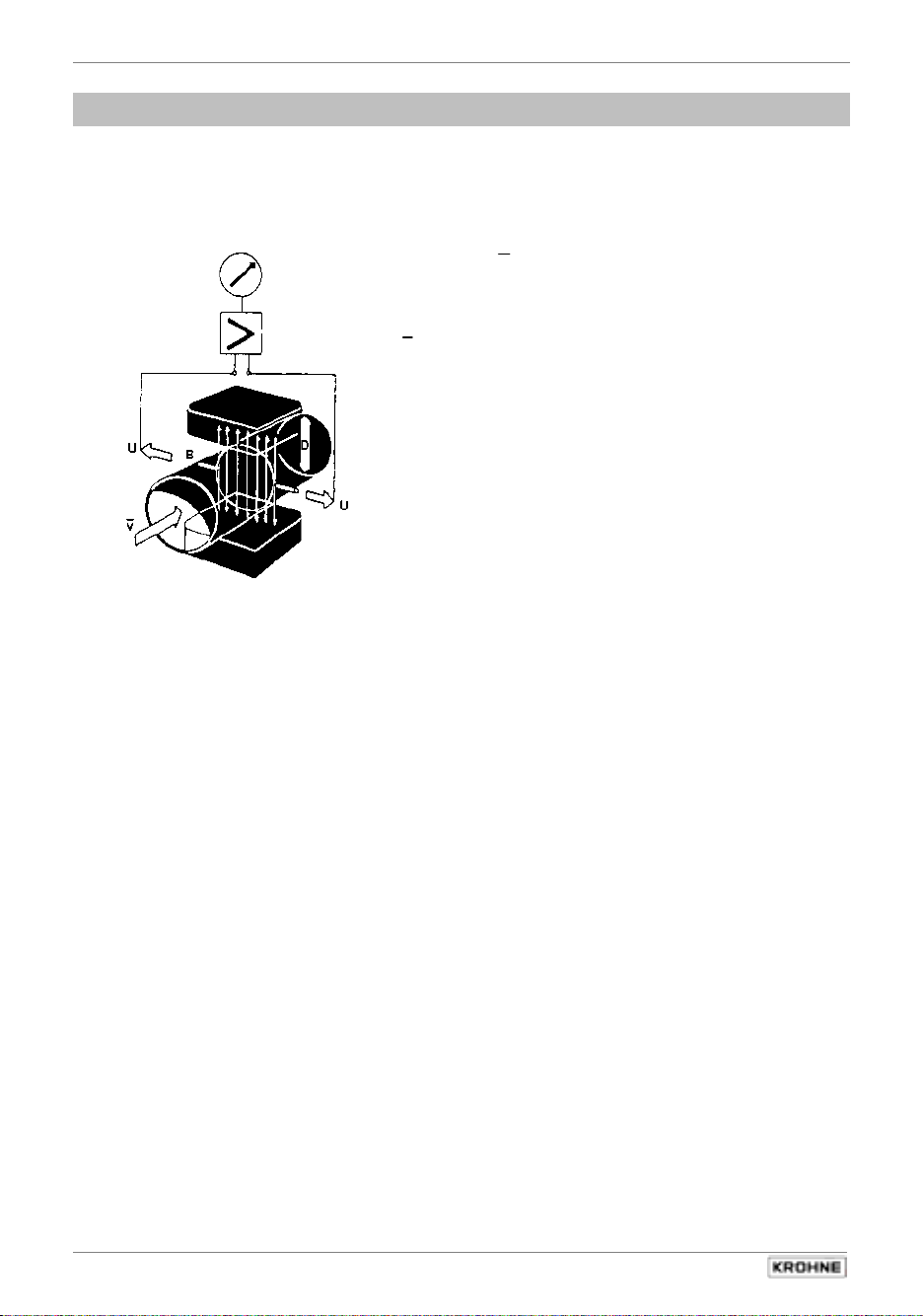
Sect. 11 Part D Technical Data, Measuring Principle and Block Diagram
0HDVXULQJSULQFLSOH
11
The flowmeter is designed for electrically conductive fluids.
Measurement is based on Faraday’s law of induction, according to which a voltage is induced in
an electrically conductive body which passes through a magnetic field. The following expression is
applicable to the voltage:
U = K × B × v × D
K an instrument constant
B magnetic field strength
v mean velocity
D pipe diameter
Inside the electromagnetic flowmeter, the fluid passes
through a magnetic field applied perpendicular to the
direction of flow. An electric voltage is induced by the
movement of the fluid (which must have a minimum
electrical conductivity). This is proportional to the mean
flow velocity and thus to the volume of flow. The
induced voltage signal is picked up by two electrodes
which are in conductive contact with the fluid and is
transmitted to a signal converter for a standardized
output signal.
This method of measurement offers the following advantages:
1) No pressure loss through pipe constriction or protruding parts.
2) Since the magnetic field passes through the entire flow area, the signal represents a mean
value over the pipe cross-section; therefore, only relatively short straight inlet pipes 5 x DN
from the electrode axis are required upstream of the primary head.
3) Only the pipe liner and the electrodes are in contact with the fluid.
4) Already the original signal produced is an electrical voltage which is an exact linear function
of the mean flow velocity.
5) Measurement is independent of the flow profile and other properties of the fluid.
The magnetic field of the primary head is generated by a square wave current fed from signal
converter to the field coils. This field current alternates between positive and negative values.
Alternate positive and negative flowrate-proportional signal voltages are generated at the same
frequency by the effect of the magnetic field, which is proportional to the current. The positive and
negative voltages at the primary head electrodes are subtracted from one another in the signal
converter. Subtraction always takes place when the field current has reached its stationary value,
so that constant interference voltages or external or fault voltages changing slowly in relation to
the measuring cycle are suppressed. Power line interference voltages coupled in the primary
head or in the connecting cables are similarly suppressed.
88
IFC 210 E
05/2002
Page 89
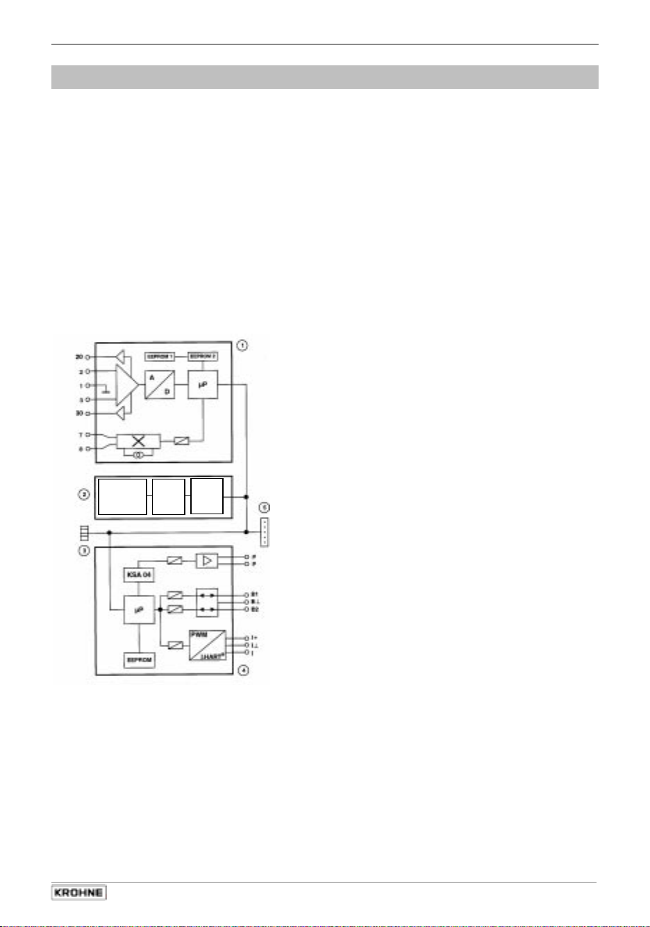
Part D Technical Data, Measuring Principle and Block Diagram Sect. 12
%ORFNGLDJUDP²VLJQDOFRQYHUWHU,)&(
12
The standard
•
outstanding accuracy
•
practice-oriented standard equipment,
current and pulse output (galvanically
isolated)
•
status and/or control input, adjustable
for numerous tasks: limit switch,
direction indication, error messages,
external initiation of functions, etc.
•
IMoCom bus, suitable for numerous
internal and external tasks
•
simplified, standard KROHNE operator
control concept
•
low power consumption
c
Printed circuit board ADC/FSV
• overdrive-proof signal processing, processes flow rate
peaks up to 20 m/s and more, fast and accurate
• digital signal processing and sequence control
• patented, high-resolution analog/digital converter,
digitally controlled and monitored
• input amplifier with facility for voltage grading of the
signalling core shield (bootstrap)
• high signal-to-noise ratio through low-loss field current
supply with high frequencies and high currents
• pulsed DC current, electronically controlled, for
supplying the magnetic coils in the primary head
• customer parameters and internal calibration data are
filed in separate EEPROMs (easily replaceable in the
event of a service)
d
Printed circuit board: display/operator control unit
• large illuminated graphic LC display
• 5 keys for operation of the signal converter
• connection to the internal IMoCom bus
• distribution of general signals, such as IMoCom bus,
supply power, etc..
IMoCom bus plug for connection of external control and
testing equipment, such as adapters and CONFIG software for
operator control via MS-DOS PC
Printed circuit board I/O-HART®, outputs and inputs
All outputs and inputs galvanically isolated
Current output I
Graphik
LCD-Display
5 keys
EEPROM
EEPROM
e
f
• for active or passive operation
• converts the digital output signal from microprocessor
µP into a proportional current
Pulse output P
• for electronic totalizers up to max. 10 kHz
• for electromechanical totalizers up to max. 50 Hz
• KROHNE-specific integrated circuit KSA 04 for fine
quantization of the output signals over a wide dynamic
range
Binary output and input B1 and B2
• any output/input combination selectable
• status output for limit value, error detection, flow
direction in F/R mode, etc.
• control input for totalizer and error resets, also for
g
holding outputs or setting to “zero“
Plug-in module slots for upgrading or retrofitting the
signal converter
• RS 485 interface module
• GTEX module for Ex-i operation of the signal converter
outside hazardous areas
• Further modules in preparation
IFC 210 E 89
05/2002
Page 90

Sect. 13 Part D Technical Data, Measuring Principle and Block Diagram
(80RGHOWHVWFHUWLILFDWH$7(;
13
90
IFC 210 E
05/2002
Page 91

Part D Technical Data, Measuring Principle and Block Diagram Sect. 13
IFC 210 E 91
05/2002
Page 92

Sect. 14 Part D Technical Data, Measuring Principle and Block Diagram
,QGH[
14
Keyword Section No. Fct. No.
A
Abbreviations 1.3.2, 1.3.4, 4.4
2.1, 4.4 F1, F2 = fuses 8.4
Accuracies 10.1 Factory settings 3.2
ADC = a nalog-digital converter 4.5, 12 Fatal error 4.5
Ambient temperature 10.1 FE = functional ground 1.2, 1.3.3, 1.3.5
Application 5.19 3.06 F ield power supply 5.16, 10.1 3.02
Automatic range change (BA) 4.4, 5.12 1.07, 1.08 Flow
B
B1/B2 output/input terminals 2.3, 2.4, 5.12
BA = automatic range change 4.4, 5.18 1.06, 1.07 Flowrate, rapid changes 6.5
Block diagram IFC 210 E 12 Flow rate (Q) 4.4, 5.12 1.04
C
C = control input 2.4, 2.5, 5.12
Cable length 1.3.4 - Fmin 5.7 1.06, 3.02
Changeover, power supply 8.2 F requency output,
Characteristics of outputs 5.22 see pulse output P 2.2, 5.7 1.06, 3.07
Clearing error messages 4.6
Coding for entry into Function(s) 4.4
setting level 5.15 3.04 Function of keys 4.3
CON FIG software 6.2 Functional checks 7.1 et seq.
Connecting & operating points - primary head 7.5
- front panel power supply 4.2 - setpoint display values 7.6
- PCBs am plifier 8.4 - system 7.4
Connection diagrams - test full scale range 7.2 2.01
- GS8A simulator 7.6 - zero 7.1 3.03
- Outputs/inputs 2.5 Functional ground FE 1.2, 1.3.3, 1.3.5
- Power supply 1.3.5, 1.3.6 Functions column 4.1-4.4
- primary head 1.3.5, 1.3.6 Fuses (F . . . ) 8.4, 9
Control input C
- connection 2.5
- description 2.4, 2.5, 5.9
Conversion factor G rounding primary head 1.3.3
- Quantity (volume) 4.4 + 5.17 3.05 GS 8A = primary (head) simulator 7.6
- Time 4.4 + 5.17 3.05
Current output I 2.1, 4.4, 5.22 1.05
Cut-off "off" value (SMU O FF) 5.3 1.03 Hardware information 7.3 2.02
Cut-off "on" value (SMU O N ) 5.3 1.03 H AR T 6.2
D
Data 4.4
Data column 4.1-4.3 I = current (analog) output 2.3, 5.6 1.05
Data errors 4.5 IEC technical standards page 0/5
Dimensions IMoCom bus (plug) 12
- IFC 210 E 10.3 Initial start-up 3
- ZD 10.3 Input (programming) 4.1 et seq.
- ZD-EEx 10.3 Instrument nameplates page 0/4
Display 4.2, 5.5 1.04 Interface RS 485 6.2, 10.1
DN = m eter size in mm 4.4 3.02 Intermediate connection box (ZD) 1.3.3, 10.3
DS, signal cable A 1.3.1 Internal electronic totalizer 5.4
E
EC = electronic totalizer 2.2, 2.5, 5.4 1.04 Keys 4.1-4.3
Electrical connection Keystroke combinations for
- GS8A simulator 7.6 - entry into setting level 4.1-4.3 3.04
- outputs and inputs 2.6 - error cancellation 4.6
- power supply 1.1, 1.3.5 - quitting setting level 4.1-4.3
Electromagnetic compatibility page 0/5 - totalizer reset 4.6
EMC = electrom echanical totalizer 2.2, 2.5, 5.7 1.06
EN technical standards page 0/5
Error 4.5 Language of display texts 5.10 3.01
Error list 4.5 LC D display, see display 4.2, 4.4, 5.4 1.04
Error (messages) 4.5 Limit message 4.4, 5.8 1.07
- cancel 4.5 Line voltage, see power supply
- limits 10.1 Low -flow cutoff (SM U) 4.4, 5.3 1.03
- reset / delete 4.6
External range change 4.4, 5.12 1.06, 1.07
3.07 (1.07,
1.08)
1.06, 1.07,
3.07
1.06, 1.07,
3.07
1.06, 1.07,
3.07
Keyword Section No. Fct. No.
F
F = forward flow
- pulsating 6.4 3.06
- rapid changes 6.5
Flow direction
Flow velocity v 4.4, 5.1 3.02
Frequency (pulse output)
- Fmax 5.7 1.06, 3.02
Full-scale range Q100%
G
GK = primary (head) constant 4.4, 5.16 3.02
H
Hazardous duty areas (Ex) 6.1, page 0/5
I
K
L
4.4, 5.6, 5.8,
5.22 1.04-1.07
4.4, 5.6, 5.8,
5.22 3.02
4.4, 5.1, 5.11,
5.12, 5.16 1.01, 3.02
92
IFC 210 E
05/2002
Page 93

Part D Technical Data, Measuring Principle and Block Diagram Sect. 14
Keyword Section No. Fct. No.
M
Magnetic field frequency 4.4 + 5.16 3.02 R = reverse flow 4.4, 5.6, 5.10 1.04-1.07
Magnetic sensors 4.2 Range change
Main menu column 4.1 - automatic 2.3, 5.9, 5.12 1.06, 1.07
Main menus 4.1 to 4.3
Mass flow measurement, R eplacement
see user defined unit 4.4, 5.17 - electronic unit 8.3
Measuring principle 11 - power fuses 8.2
Menu 4.1, 4.4 Reset totalizers 4.4, 5.9
Meter size (DN) 4.4, 5.1, 5.4, 5.16 3.02 R everse flow (R) 4.4, 5.10, 5.22 1.04-1.07
Re ve r t to
N
Numerical format, display 5.5 1.04 - m ain menu column 4.1-4.3
- measuring mode 4.1-4.3
O
Option = optional equipment 6.2, 10.1 S = Status output 2.4, 4.4, 5.8 1.06, 1.07, 3.07
Order numbers 9 Safety isolation 2.1
Outputs Setting level 4.1-4.4 1.00 et seq.,
- characteristics 5.15 2.00 et seq.,
- connection diagrams 2.5 3.00 et seq.
- setting 4.4 Signal converter IFC 020
- - I 5.6 1.05 - accuracies 10.3
- - P 5.7 1.06, 3.07 - cable A 1.3.1
- - S 5.8, 5.16
- voltage stable when - connecting & operating points 4.2, 8.9
measuring tube em pty 6.3 - connection to power 1.2
Overflow, display 5.5 1.04 - functional checks 7.1-7.6,
Overranged - fuses, power 8.5
- I (current output) 2.2, 2.6, 5.6, 5.8 1.06, 1.07 - mounting location 1.1
- P (pulse output) 2.3, 2.6, 5.7, 5.8 1.06, 1.07 - nameplates 10.5
Overvoltage class 1.2, 6.1 - operator control 4.1-4.3
- power consumption 10.4
P
P = pulse output 2.2, 4.4, 5.7 1.06 - spare parts 9
PCB = printed circuit boards 8.4 - technical data 10.1-10.4
PC software 6.2 Simulator GS 8A 7.6
PE = protective conductor 6.1 SM U = low-flow cutoff 4.4, 5.3 1.03
Power supply (= line voltage) Software 6.2
- changeover 8.2 Spare parts, see order num bers 9
- connection 2.1, 10.4 Status output S 2.4, 4.4, 5.8 1.06, 1.07, 3.07
- consumption 10.4
- failure 4.5, 7.4
- frequency 1.2, 10.1 3.02 T = time constant 5.2 1.02
- voltage 1.2, 10.1+B49 T echnical data
Primary constant, see G K 4.4, 5.12 3.02 - accuracies 10.3
Primary head - dimensions & w eights 10.2
- constant, see GK 4.4, 5.16 3.02 - signal converter IFC 020 10.1-10.4
- simu lato r G S 8A 7.6
- testing 7.5 Tests, see functional checks 7.1 et seq.
Primary simulator, see GS 8A 7.6 Time constant (T) 5.1 1.02
Printed circuit boards, see PCB 8.4 Totalizer (internal electronic) 5.4 1.06, 3.07
Program organization 4.1 Trip point 2.3, 5.8 1.0_
Programming = input 4.1-4.3 Troubleshooting, see
Programming mode, entry into 4.1-4-3 functional checks 7.1 et seq.
Protective conductor PE 6.1
Pulsating flow 6.4, 7.4 3.06
Pulse output P 2.2, 2.5, 4.4, 5.1, 5.22 1.06
Pulse width 4.4, 5.7 1.06 Units for
Pulses per unit time 4.4, 5.7 1.06 - display 4.4, 5.4 1.04
Pulses per unit volume 4.4, 5.7 1.06 - flow 4.4, 5.1 1.01
- P 4.4, 5.7 1.06
Q
Q = flow rate 4.4, 5.12 1.04
Q100% = full-scale range
v = flow velocity 4.4, 5.1 3.02
VDE standards 1.1
W eights, see dimensions 10.3
Zero check (adjustment) 7.1 3.03
1.00, 2.00,
3.00
- functions column 4.1-4.3
1.06, 1.07,
3.07
- printed circuit boards 8.9
User-defined unit 4.4, 5.13 3.05
4.4, 5.1, 5.11, 5.12,
5.16 1.01, 3.02
Keyword Section No. Fct. No.
R
- external 2.3, 5.9, 5.18 1.06, 1.07
S
- changeover, power supply 8.2
T
Terminals B1/B2 2.1, 2.6, 5.16
U
V
W
Z
3.07 (1.06,
1.07)
IFC 210 E 93
05/2002
Page 94

94
IFC 210 E
05/2002
Page 95

.
,I\RXQHHGWRUHWXUQIORZPHWHUVIRUWHVWLQJ
RUUHSDLUWR.52+1(
Your electromagnetic flowmeter
has been carefully manufactured and tested
•
by a company with ISO 9001 certification
and volumetrically calibrated in one of the
•
world’s most accurate test rigs.
If installed and operated in accordance with these
operating instructions, your flowmeter will rarely
present any problems.
Should you nevertheless need to return a
flowmeter for checkout or repair, please pay strict
attention to the following points:
Due to statutory regulations concerning protection
of the environment and the health and safety of
our personnel, KROHNE may only handle, test
and repair returned flowmeters that have been in
contact with liquids if it is possible to do so
without risk to personnel and environment. This
means that KROHNE can only service your
flowmeter if it is accompanied
SPECIMEN certificate
Company: .......................................................... Address: ................................................................
Department: ....................................................... Name: ....................................................................
Tel. No.: ............................................................. Fax-No.: .................................................................
The enclosed electromagnetic flowmeter
Type: .................................................................. .: ..............................................................................
KROHNE Order No. or Series No.: ................... ................................................................................
has been operated with the following liquid: ........
Because this liquid is
water-endangering * / toxic * / caustic * / flammable *
we have
- checked that all cavities in the flowmeter are free from such substances *
- flushed out and neutralized all cavities in the flowmeter *
(* delete if not applicable)
We confirm that there is no risk to man or environment through any residual liquid contained in
this flowmeter.
Date: .................................................................... Signature: ............................................................
..............................................................................
Company stamp:
IFC 210 E 95
05/2002
by a certificate in line with the following model
confirming that the flowmeter is safe to handle.
If the flowmeter has been operated with toxic,
caustic, flammable or water-endangering liquids,
you are kindly requested
to check and ensure, if necessary by rinsing or
•
neutralizing, that all cavities in the flowmeter
are free from such dangerous substances.
(Directions on how you can find out whether
the primary head has to be opened and then
flushed out or neutralized are obtainable from
KROHNE on request.)
to enclose a certificate with the flowmeter
•
confirming that the flowmeter is safe to handle
and stating the liquid used.
KROHNE regret that they cannot service your
flowmeter unless accompanied by such a
certificate.
................................................................................
 Loading...