

Page 1

Condensed
Instructions
IFC 210 E
IFC 210 E-EEx
Signal converters for
electromagnetic flowmeters
©
KROHNE 05/2002 7.10006.11.00
Applicable to
Software Versions
● Operating and check elements
No. 3.18393.01
● Amplifier (ADC)
No. 3.17116.01
● Outputs/inputs (I/O)
No. 3.19005.01
Contents
1 Electrical connection: Power Pages 2-11
2 Electrical connection: Outputs Pages 12-18
3 Start-up Pages 19
4 Operator control of signal converter Pages 20-27
PLEASE NOTE
These concise instructions do not include the following:
device description, technical data, standards, approvals, etc.,
nor conditions pertaining to product liability and warranty.
The operator is, however, obligated to take note of these
sections in the detailed Installation and Operating Instructions.
References to chapters
All references to chapters in these Condensed Instructions
refer to those of the detailed “Installation and Operating
Instructions”. It is important that the detailed Instructions
be referred to for all chapters omitted from these
Condensed Instructions. This particularly concerns
installation and operation in hazardous areas!
Page 2
Sect. 1.1 Part A System installation and start-up
1 (OHFWULFDOFRQQHFWLRQSRZHUVXSSO\
1.1 Location and important installation notes
Electrical connection in accordance with VDE 0100
•
installations with line voltages up to 1000 V” or
•
Do not cross or loop
•
•
•
•
•
•
•
•
separate cable
Use
outputs and inputs.
Protect flowmeters or switchgear cabinets with built-in devices from direct
sunshade if necessary.
installed in switchgear cabinets
When
use fans or heat exchangers. (dust-free air and no aggressive gases)
Do not expose signal converters to intense
distance between primary head and signal converter
Keep
Sect. 1.3.4 for maximum permissible length of signal and field current cables.
Use the supplied KROHNE
optional
Always
ensure
head.
If the GK is not identical, set the signal converter to the GK of the primary head.
Refer also to Section 4.
Dimensions of signal converter,
signal cable B
calibrate
primary constant GK is identical
IMPORTANT!
For EEx versions, also pay regard to all special directions included in Sect. 6.1
and 13.
Only the EEx primary head may be installed in the hazardous area.
The signal converter must be installed outside the hazardous area!
cables
.
entries (see below) for power supply, field current cables, signal lines,
signal cable A
(Type BTS).
primary head and signal converter
refer to Section 10.4.
equivalent others national regulations
, signal converters must be adequately cooled, e.g.
vibration
(Type DS), standard length 10 m (33 ft), or
; refer to instrument nameplate for the primary
”Regulations governing heavy-current
.
together
sunlight
as short as possible. Refer to
. Therefore, when installing,
. Fit a
.
2 IFC 210 E
05/2002
Page 3

Part A System installation and start-up Sect. 1.2
1.2 Power supply - Electrical connection
PLEASE NOTE !
•
Rated values: The flowmeter housings meets the requirements of IP 20 in conformity
with EN 60529.
No protection against water and moisture. If necessary, take appropriate protective
measures.
The selected creepage distances and clearances have been dimensioned in conformity with
VDE 0110 and IEC 664 for contamination category 2. Supply circuits and output circuits are
designed to meet the standards of overvoltage class II.
•
Fuse protection, disconnecting device: fuse protection for the feeding power circuit, and also
a disconnecting device (switch, circuit breaker) for isolating the signal converters must be
provided (see also Sect. 1.3.5).
Power supply 100-230 V AC (Tolerance zone: 85-255 V AC)
•
Note information on instrument nameplate: supply voltage and frequency
•
Connection diagrams for electrical connection between primary head and signal converter:
refer to Section 1.3.5.
Power supply 24 Volt AC / DC (Tolerance zone: AC 20.4 - 26.4 V / DC 18 - 31.2 V)
•
Note information on instrument nameplate: supply voltage and frequency
•
For measurement reasons, connect an FE functional ground conductor.
•
If connected to a functional extra-low voltage source (24 V AC / DC, 48 V AC), provide for
protective separation (PELV) in conformity with e.g. VDE 0100 / VDE 0106 or
IEC 364 / IEC 536, or equivalent national regulations.
•
Connection diagrams for power supply and electrical connection between primary head and
signal converter: refer to Section 1.3.5.
IMPORTANT!
For EEx versions, also pay regard to all special directions included in Sect. 6.1
and 13.
Only the EEx primary head may be installed in the hazardous area.
The signal converter must be installed outside the hazardous area!
IFC 210 E 3
05/2002
Page 4

Sect. 1.3.1 Part A System installation and start-up
1.3 Electrical connection of separate primary heads
1.3.1 General remarks on signal lines A and B and field current line C
Proper operation of the equipment is ensured when KROHNE signal lines A and B are used with
foil screen and magnetic shield.
•
Signal lines must be firmly installed.
•
Shields are connected via stranded drain wires.
•
Underwater or underground routing is possible.
•
Insulating material flame-retardant to IEC 332.1 / VDE 0742.
•
Low-halogen, unplasticized signal lines which remain flexible at low temperatures.
Signal line A (type DS) with double shielding
1 Stranded drain wire, 1st shield, 1.5 mm
2 Insulation
3 Stranded wire 0.5 mm2 (3.1 red/3.2 white)
4 Special foil, 1st shield
5 Insulation
6 Mu-metal foil, 2nd shield
7 Stranded drain wire, 2nd shield, 0.5 mm2
8 Outer sheath
Signal line B (type BTS) with triple shielding (bootstrap line)
1 Dummy glider wire
2 Insulation (2.1 red/2.2 white)
3 Special foil, 1st shield (3.1/3.2)
4 Insulation (4.1/4.2)
5 Stranded wire 0.5 mm
6 Stranded drain wire, 1st shield, 0.5 mm2 (6.1 / 6.2)
7 Special foil, 2nd shield
8 Stranded drain wire, 2nd shield, 1,5 mm2
9 Insulation
10 Mu-metal foil, 3rd shield
11 Stranded drain wire, 3rd shield,, 0,5 mm2
12 Outer sheath
Field current line C
Line 2 × 0,75 mm2, 2 × 1,5 mm2 or 4 × 1,5 mm2Cu, single shielding
(Cu = copper cross section)
The cross section depends on the required cable length, see table in Section 1.3.4.
IMPORTANT!
For EEx versions, also pay regard to all special directions included in Sect. 6.1
and 13.
Only the EEx primary head may be installed in the hazardous area.
The signal converter must be installed outside the hazardous area!
2
2
(5.1 red/5.2 white)
4 IFC 210 E
05/2002
Page 5

Part A System installation and start-up Sect. 1.3.2
1.3.2 Stripping (preparation) of signal cables
Please note: The numbers in the drawings designate the stranded drain wires of signalling cables
A and B, see sectional drawings in Sect. 1.3.1.
primary head Converter
Length primary head Length Converter
mm inch mm inch
a 90 3.60 a 40 2.80
b 8 0.30 b 10 0.30
c 25 1.00
d 8 0.30 d 5 0.30
e 70 2.80 e 20 2.00
Signal cable A (type DS),
double shielding
for primary head
Signal cable A (type DS),
double shielding
for IFC 210 E Converter
Signal cable A
bending radius
bending radius
≥
50 mm (≥ 2”)
≥
50 mm (≥ 2”)
Signal line B (type BTS),
with triple shielding (bootstrap)
for primary head
Signal cable B
bending radius
bending radius
≥
50 mm (≥ 2”)
≥
50 mm (≥ 2”)
Customer-supplied materials
V Tin-coat all stranded drain wire ends!
W Insulation tubing (PVC), Ø 2.0-2.5 mm (Ø 1”)
X Heat-shrinkable tubing or cable sleeve
Y Wire end sleeve to DIN 41 228: E 1.5-8
Z Wire end sleeve to DIN 41 228: E 0.5-8
Signal line B (type BTS),
with triple shielding (bootstrap)
for IFC 210 E Converter
IFC 210 E 5
05/2002
Page 6
Sect. 1.3.3 Part A System installation and start-up
1.3.3 Grounding of primary head
•
All flowmeters must be grounded.
•
The grounding conductor should not transmit any interference voltages.
•
Do not ground any other electrical device together with this conductor.
•
The primary head is connected to ground by means of an FE functional ground conductor.
•
Special information on grounding various primary heads is contained in the separate
installation instructions for primary heads.
•
These instructions also contain detailed descriptions on how to use grounding rings and how
to install primary heads in metal or plastic pipes or internally coated pipelines.
IMPORTANT!
For EEx versions, also pay regard to all special directions included in Sect. 6.1
and 13.
Only the EEx primary head may be installed in the hazardous area.
The signal converter must be installed outside the hazardous area!
1.3.4 Cable lengths (max. distance between signal converter and primary head)
Abbreviations and explanatory notes
used in the following tables, diagrams and connection diagrams
A Signal cable A (type DS), with double shielding, see diagram A for max. length
B Signal line B (type BTS) with triple shielding, max. length see diagram B
C Field current cable min. cross-section (AF) and max. length, see Table
D High-temperature silicone cable, 3 × 1.5 mm
2
(14 AWG) Cu, (with single shielding,
max. length 5 m (16 ft)
E High-temperature silicone cable, 2 × 1.5 mm
2
(14 AWG) Cu, max. length 5 m (16 ft)
Cross section of field current line C in Cu, see table
A
F
L Cable length
Electrical conductivity of the process liquid
κ
ZD Intermediate connection box required in connection with cables D and E for primary heads
ALTOFLUX IFS 4000 F, PROFIFLUX IFS 5000 F and VARIFLUX IFS 6000 F in cases
where process temperatures exceed 150 °C (302 °F)
6 IFC 210 E
05/2002
Page 7
Part A System installation and start-up Sect. 1.3.4
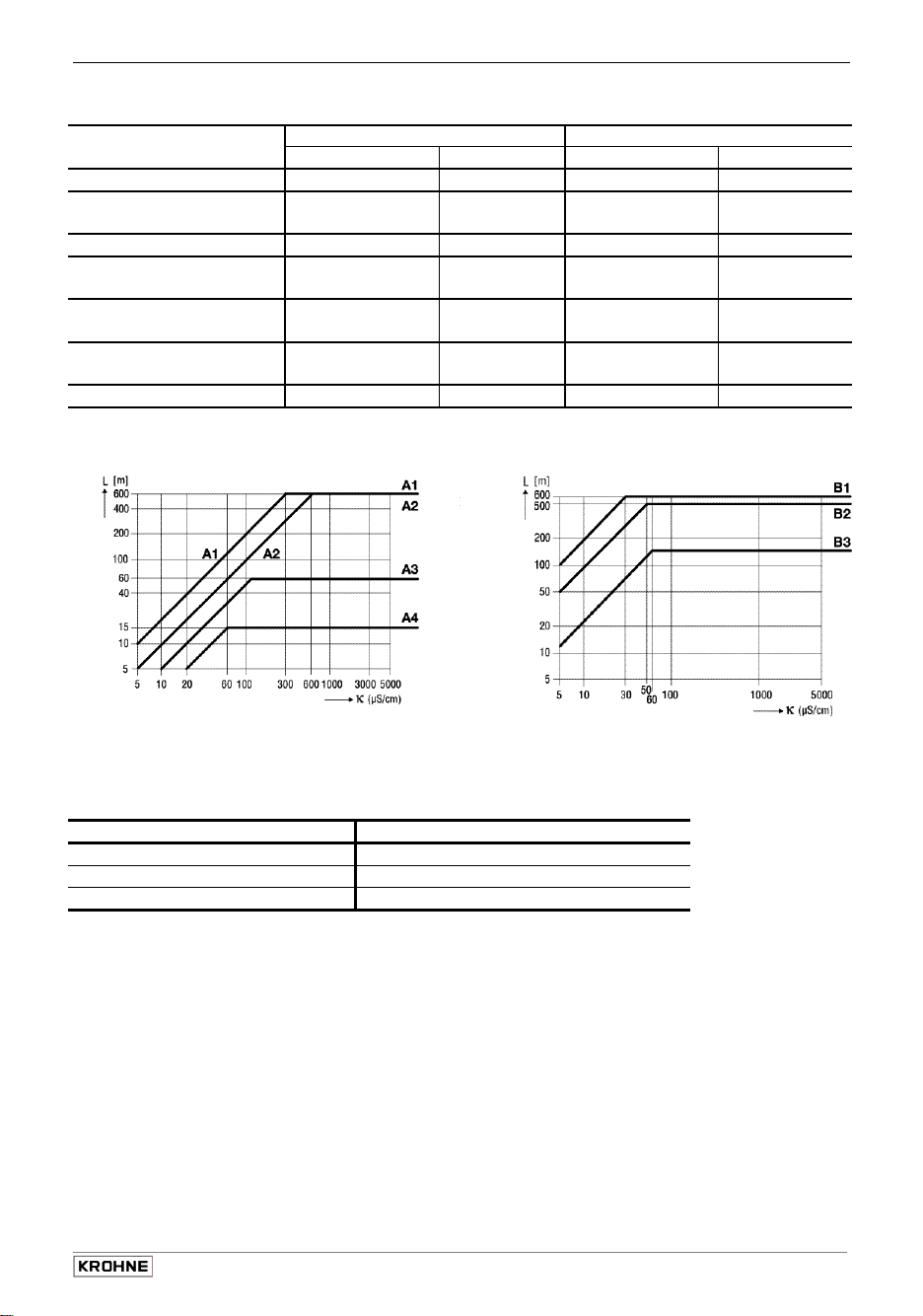
Recommended length of signal cable A (Type DS) and B (Type BTS)
Primary head Meter size Signal cable
DN mm inch A B
AQUAFLUX F 10 - 1600
ECOFLUX IFS 1000 F 10
- - 15
25
ALTOFLUX IFS 2000 F 150 - 250 6 - 10 A1 B1
ALTOFLUX IFS 4000 F 10
200 - PROFIFLUX IFS 5000 F 2.5
- - 15
25
VARIFLUX IFS 6000 F 2.5 - 15
25 - 80 1 - 3 A2 B2
ALTOFLUX M 900 10 - 300
150
150
1600
100
3
/8 - 64 A1 B1
3
/
- - ½
8
1
3
/
8
8
1
/
10
1
1
/10 - ½ A4 B3
3
/8 - 12 A1 B1
6
- - 6
64
- - ½
4
A4
A3
A2
A1
A4
A2
B3
B2
B2
B1
B3
B2
Diagram A Diagram B
Field current cable C
Length L Cross section AF (Cu), minimum
0 – 150 m 5 – 500 ft 2 x 0.75 mm2 / 2 × 18 AWG
150 – 300 m 500 – 1000 ft 2 x 1.50 mm2 / 2 × 14 AWG
300 – 600 m 1000 – 1900 ft 4 x 1.50 mm2 / 2 × 12 AWG
IFC 210 E 7
05/2002
Page 8
Sect. 1.3.5 Part A System installation and start-up
1.3.5 Connection diagrams for power supply and primary head
PLEASE NOTE: Undocumented contacts/terminals to remain unwired.
The figures in brackets indicate the stranded drain wires for the shields
(see cross-sectional drawing of signal cable in Section 1.3.1).
•
Electrical connection to VDE 0100 "Regulations governing heavy-current installations with
line voltages up to 1000 V" or equivalent national regulations.
•
24 V AC / DC power supply:
Functional extra-low voltage with protective separation in
conformity with VDE 0100, Part 410 or equivalent national
regulations (IFC 020 E: 24 V DC in preparation).
•
Fuse protection of the feed line circuit with I
≤ 16 A is required. Also, a disconnecting
RAT
device (switch/circuit breaker) must be provided in the vicinity of the solidly connected signal
converters or device groups, refer to EN 61 010. This disconnecting device must be easy to
reach and also identifiable as such.
Contacts 2d, 2z, 4d, 4z of
*
XA must be electrically
connected.
Connection to 8d and/or
**
8z of XA.
Contacts d2 to d32 of XB
***
are of leading type, for
connection of PE (safety
conductor) or FE
(functional ground).
At least 4 contacts with
adequate cross-section to
be electrically connected.
Important:
Electrical connection of EEx primary heads and EEx signal converters
To be carried out as described in Sect. 1.3.6.
8 IFC 210 E
05/2002
Page 9

Part A System installation and start-up Sect. 1.3.5
I Signal cable A (type DS) II Signal cable B (type BTS)
IFC 210 E IFC 210 E
Process temperature < 150°C (302°F)
Primary head Primary head
III Signal cable A (type DS) IV Signal cable B (type BTS)
IFC 210 E IFC 210 E
Process temperature > 150°C (302°F)
Primary head Primary head
IFC 210 E 9
05/2002
Page 10

Sect. 1.3.6 Part A System installation and start-up
1.3.6 EEx-Connection diagrams for power supply and primary head
Connection diagrams
PLEASE NOTE: Undocumented contacts/terminals to remain unwired.
The figures in brackets indicate the stranded drain wires for the shields
(see cross-sectional drawing of signal cable in Section 1.3.1).
•
Electrical connection to VDE 0100 "Regulations governing heavy-current installations with
line voltages up to 1000 V" or equivalent national regulations.
•
24 V AC / DC power supply:
Functional extra-low voltage with protective separation in
conformity with VDE 0100, Part 410 or equivalent national
regulations (IFC 020 E: 24 V DC in preparation).
•
Fuse protection of the feed line circuit with I
≤ 16 A is required. Also, a disconnecting
RAT
device (switch/circuit breaker) must be provided in the vicinity of the solidly connected signal
converters or device groups, refer to EN 61 010. This disconnecting device must be easy to
reach and also identifiable as such.
Contacts 2d, 2z, 4d, 4z of
*
XA must be electrically
connected.
Connection to 8d and/or
**
8z of XA.
Contacts d2 to d32 of XB
***
are of leading type, for
connection of PE (safety
conductor) or FE
(functional ground).
At least 4 contacts with
adequate cross-section to
be electrically connected.
Important:
In respect of EEx versions, pay regard to all directions marked with the symbol,
and also the information given in Sect. 6.1 and 13.
Only the EEx primary head may be installed in the hazardous area.
The signal converter must be installed outside the hazardous area!
10 IFC 210 E
05/2002
Page 11

Part A System installation and start-up Sect. 1.3.6
I Signal cable A (type DS) II Signal cable B (type BTS)
IFC 210 E-EEx IFC 210 E-EEx
Process temperature < 150°C (302°F)
PE/PA
PE/PA
Hazardous area
PA
Primary head Primary head
Hazardous area
PA
III Signal cable A (type DS) IV Signal cable B (type BTS)
Process temperature > 150°C (302°F)
IFC 210 E-EEx IFC 210 E-EEx
PE/PA
Hazardous area
PE/PA
Hazardous area
PA
PA
Primary head Primary head
IFC 210 E 11
05/2002
PA
PA
Page 12

Sect. 2.1 Part A System installation and start-up
(OHFWULFDOFRQQHFWLRQRIRXWSXWVDQGLQSXWV
2
Important:
In respect of EEx versions, pay regard to all directions marked with the symbol,
and also the information given in Sect. 6.1 and 13.
Only the EEx primary head may be installed in the hazardous area.
The signal converter must be installed outside the hazardous area!
2.1 Current output I
The current output is galvanically isolated from all input and output circuits.
•
Setting data and functions can note down in Section 3.3.
•
Please also refer to Sect. 3.2 Factory settings.
Typical current
•
output
All operating data and functions can be set, see Sect. 4 and 5.6, Fct. 1.05 for operator control
•
The current output can also be used as an internal voltage source for the binary outputs and
•
inputs.
U
•
= 22-25 V DC
int
I = 23 mA when operated
output
I = 3 mA when operated
•
Connection diagrams
, see Sect. 2.5: diagrams
approx. 22-25 V DC positive
voltage of current output
current sink
chassis ground, current output
without
with
receiver instruments at the current
receiver instruments at the current output
c d e g i k l
12 IFC 210 E
05/2002
Page 13

Part A System installation and start-up Sect. 2.2
2.2 Pulse output P
•
The pulse output is galvanically isolated from the current output and all input circuits.
•
Setting data and functions can note down in Section 3.3.
Please also refer to Sect. 3.2 Factory settings.
•
Typical pulse output P
•
All operating data and functions can be set, see Sect. 4 and 5.7, Fct. 1.06 for operator control
•
The pulse output can be operated in the active or passive mode.
•
Active mode:
•
Passive mode:
Please note:
A fixed pulse width (0.01 – 1s) must be set for operation with EMC
•
Digital pulse division, interpulse period is non-uniform. Therefore, if frequency meters or
•
cycle counters are connected, allow for minimum counting interval:
•
gate time, counter ≤
•
Connection diagrams, see Sect. 2.5: diagrams
The current output is the internal voltage source,
connection of electronic totalizers (EC)
External DC or AC voltage source required,
connection of electronic (EC) or electromechanical (EMC) totalizers
totalizer. Only then is an optocoupler active for higher output currents.
1000
[Hz]
P
100%
e
f k l
P pulse output
P pulse output
IFC 210 E 13
05/2002
Page 14

Sect. 2.3 Part A System installation and start-up
2.3 Status outputs B1 and B2
•
The status outputs are galvanically isolated from the current output and all input circuits.
•
Setting data and functions can note down in Section 3.3.
Please also refer to Sect. 3.2 Factory settings.
•
Typical status outputs B1 and/or B2
B1/B2 status outputs B1/B2
B⊥ chassis ground,
binary outputs and inputs
•
All operating data and functions can be set,
see Sect. 4 and 5.9, Fct 1.07 and/or 1.08 for operator control
The status outputs can be operated in the active or passive mode.
Active mode: The current output is the internal voltage source.
Passive mode: External DC or AC voltage source required.
Characteristics of the status outputs Switch open Switch closed
OFF (switched off) no function
ON (e.g. operation indicator) power OFF Hilfsenergie EIN
SIGN I (F/R mode) Forward flow Reverse flow
SIGN P (F/R mode) Forward flow Reverse flow
TRIP POINT (limit switch) inactive active
AUTO RANGE (automatic range
change)
OVERFLOW I (I overranged) current output OK current output overranged
OVERFLOW. P (P overranged) pulse output OK pulse output overranged
SMU I (low-flow cutoff active) Inactive active
SMU P (low-flow cutoff active) Inactive active
Inverse B1 (switches B2 inversely to B1) B2 open, B1 closed B2 closed, B1 open
ALL. ERROR (all errors) errors no error
FATAL.ERROR (fatal errors only) errors no error
EMPTY PIPE (option) when measuring tube is empty when measuring tube is full
high range low range
•
Connection diagrams, see Sect. 2.5: diagrams
g
h k l
14 IFC 210 E
05/2002
Page 15

Part A System installation and start-up Sect. 2.4
2.4 Control inputs B1 and B2
•
The control inputs are galvanically isolated from the current output and all input circuits.
•
Setting data and functions can note down in Section 3.3.
Please also refer to Sect. 3.2 Factory settings.
•
Typical current inputs B1 and B2
B1/B2
B⊥
•
All operating data and functions can be set,
see Sect. 4 and 5.10, Fct 1.07 and/or 1.08 for operator control
•
The control inputs must be operated in the passive mode.
Function of the control inputs inactive active
no voltage voltage present
Off No functions
External range High range Low range
Hold measured values Measured values follow the Hold measured values
measurement
Measured values at zero Measured values follow the
measurement
Measured values set to
“zero“
Reset totalizer inactive Reset totalizer
Delete errors inactive Delete error messages
Connection diagram, see Sect. 2.5: diagram
i
j
IFC 210 E 15
05/2002
Page 16

Sect. 2.5 Part A System installation and start-up
2.5 Connection diagrams for outputs and inputs
I
P
B1, B2
Current output I
c
= 0/4-20 mA
U
< 800 Ω
R
L
Important:
In respect of EEx versions, pay regard to all directions marked with the symbol,
and also the information given in Sect. 6.1 and 13.
Only the EEx primary head may be installed in the hazardous area.
The signal converter must be installed outside the hazardous area!
Current output (included HART
Pulse output
Status output (S) and / or
Control input (C)
Totalizer
- electromechanical (EMC)
- electronic (EC)
milliammeter
0-20 mA or 4-20 mA and other
Key, N/O contact
External voltage source (U
DC or AC voltage,
connection polarity arbitrary
DC voltage,
external power source (U
®
Please note ! Unwired contacts may not have
)
any conductive connection with other electrically
conducting parts.
Electrical connection to socket connector XC
Wiring diagrams c to l of outputs and inputs.
Interface operation with HART® or
RS 485 (Option) see Sect. 6.2.1 and 6.2.2.
Power for operation (activation) of outputs and
inputs supplied by the current output.
),
ext
Active mode
External power source required for operation
(activation) of outputs and inputs.
),
ext
Passive mode
note connection polarity
aktiv
Current output I
d
15-22 V DC 22-32 V DC
U
ext
R
0-500 Ω 0-800
L
= 0/4-20 mA
I
passiv
Ω
16 IFC 210 E
05/2002
Page 17

Part A System installation and start-up Sect. 2.5
Pulsoutput P
e
for electronic totalizer (EC)
= 22-25 V DC from current output
U
int
≤ 3 mA operation with current output I
I
max
≤ 23 mA operation
I
max
activ
without
current output I
R = 10 kΩ, prevents incorrect counts
when pulse output in open circuit
Where frequencies are > 100 Hz, use shielded
cables (RFD)
Statusoutput S
g
(connection to B2 and/or B1)
= 22-25 V DC from current output
U
int
≤ 3 mA operation with current output I
I
max
≤ 23 mA operation without current output I
I
max
activ
Pulsoutput P
f
for electronic totalizer (EC) or
passiv
electromechanical totalizer (EMC)
EMC:
EC:
Pulses
R (load)
U
I
max
U
≤ 32 V DC /
ext
≤ 150 mA
≤ 32 V DC
ext
≤ 1 kHz
1-10 kΩ 1-3 kΩ
≤ 24 V AC
f ≤ 50 Hz
≤ 20 mA
I
max
< 10 kHz
R = load impedance with EC totalizer operation; for
value refer to table above
Where frequencies are > 100 Hz, use shielded cables
(RFD)
Statusoutput S
h
(connection to B2 and/or B1)
U
≤ 32 V DC / ≤ 24 V DC
ext
I
max
≤ 150 mA
passiv
IFC 210 E 17
05/2002
Page 18

Sect. 2.5 Part A System installation and start-up
Control input C
i
(connection to B2 and/or B1)
= 22-25 V DC from current output
U
int
≤ 4 mA (max. contact rating)
I
con
active
Control input C
j
(connection to B2 and/or B1)
U
≤ 32 V DC / ≤ 24 V AC
ext
I
con
≤ 6 mA (max. contact rating)
passive
F/R measurement (F=forward) (R=reverse)
k
Current output I
pulse output P
without external changeover relay
= 22-25 V DC from current output
U
int
≤ 3 mA operation
I
max
≤ 23 mA operation
I
max
and/or
active
(for EC)
aktive
current output I
with
without
current output I
F/R measurement (F=forward) (R=reverse)
l
Current output I
pulse output P
without external changeover relay
EMC:
EC:
Pulses
R (load)
≤ 32 V DC /
U
ext
≤ 150 mA
I
max
≤ 32 V DC
U
ext
and/or
passive
(for EC or EMC)
passive
≤ 24 V AC
f ≤ 50 Hz
≤ 20 mA
I
max
≤ 1 kHz
< 10 kHz
1-10 kΩ 1-3 kΩ
= 10 kΩ, prevents incorrect counts
R
when pulse output in open circuit
Where frequencies are > 100 Hz, use shielded
*
cables (RFD)
R = load impedance with EC totalizer operation; for
value refer to table above
Where frequencies are > 100 Hz, use shielded
*
cables (RFD)
18 IFC 210 E
05/2002
Page 19

Part A System installation and start-up Sect. 3.1
6WDUWXS
3
3.1 Power-on and measurement
•
Before powering the system, please check that it has been correctly installed according to
Sect. 1 and 2.
•
The flowmeter is delivered ready for operational use. All operating data have been factory set
in accordance with your specifications.
Please refer to Sect. 3.2 “factory settings”.
•
Power the unit, and the flowmeter will immediately start process flow measurement.
•
Refer to Sect. 4 and 5 for operator control.
3.2 Factory setting
All operating data are factory set according to your order specifications.
If you have not made any particular specifications at the time of ordering, the instruments will be
delivered with the standard parameters and functions listed in the Table below.
To facilitate easy and rapid initial start-up, current output and pulse output are set to process flow
measurement in “2 flow directions”, so that the current flowrate is displayed and the volumetric
flow counted independent of the flow direction. The measured values may possibly be shown with
a “ – ” sign.
This factory setting for the current and pulse outputs may possibly lead to measuring errors,
particularly in the case of volume flow counting:
For example, if pumps are switched off and a “backflow” occurs which is not within the range of
the low-flow cutoff (SMU), or if separate displays and counts are required for both flow directions.
To avoid faulty measurements, therefore, it may be necessary to change the factory setting of
some or all of the following functions:
– low-flow cutoff SMU, Fct. 1.03, Sect. 5.3
– display, Fct. 1.04, Sect. 5.4
– current output I, Fct. 1.05, Sect. 5.6
– pulse output P, Fct. 1.06, Sect. 5.7
Operation see
Standard factory settings
Function Setting Function Setting
1.01 Full-scale range Q
1.02 Time constant 3 s, for I, B1, B2 directions
and display 1.08 Control input B2 off
1.03 Low-flow ON: 1% 3.01 Language for display only English
cutoff SMU OFF: 2% 3.02 Flowmeter
1.04 Display diameter see nameplate
flow rate m3/hr or US Gal /mi n flow direction (see arrow
totalizer(s) m3 or US Gal on primary head) } + direction
Messages no 3.04 Entry code no
Trend Mittelwert 3.05 User unit Liter/hr or USMGal/day
Updating 1 sec. 3.06 Application: Flow steady
Scaling auto 3.07 Hardware: Terminal B1 Statusoutput
1.05 Current output I Terminal B2 Control input
function 2 directions 3.08 Location ALTOMETER
Range I 4-20 mA 3.09 Communication off
I Max 22 mA
I Error 22 mA
1.06 Pulse output P
function 2 directions
pulse width 50 ms
pulse value 1 pulse/s
Section 4 and 5
1.07 Status output B1 flow
100%
.
IFC 210 E 19
05/2002
Page 20

Sect. 2.5 Part A System installation and start-up
2SHUDWLRQRIWKHVLJQDOFRQYHUWHU
4
4.1 KROHNE operator control concept
1 3 6. 4 9
m 3 /hr
→
Measuring mode
Code 1
Menu column
3.00 Installation
2.00 Test
When this display appears, press following keys:
→ → → ↵ ↵ ↵ ↑ ↑ ↑
Function column
3.09 Communication
3.08 Location
3.07 Hardware
3.06 Application
3.05 User Units
3.04 Entrycode
3.03 Zero Point
3.02 Flow Meter
3.01
Language
2.03 Test Display
2.02 Hardwareinfo
2.01 Test Q
1.08 Out-/Input B2
Data column
1.07 Out-/Input B1
1.06 Pulsoutput P
1.05 Currentoutput I
1.04 Display
1.03 Low Flow Cutoff
1.02Timeconstant
1.01 Full Scale
→
↑
Direction of movement
1.00 Operation
↑
↓
↵
20 IFC 210 E
↓
Sect.
4.4
↵
05/2002
see
→
Page 21

Part B IFC 210 Signal converter Sect. 4.2
4.2 Table of settable functions
Fct. Display- Texts Description and settings
1.00 OPERATION Operations menu
1.01 FULL SCALE Full-scale range for flowrate Q
Select unit
3
• m
/hr • Liter/Sec • US.Gal/min
• user unit, factory set is Liter/hr or US MGal/day (see Fct. 3.05)
Press
key to transfer to number setting.
→
Setting ranges:
The ranges are dependent on the meter size (DN) and the
flow velocity (v):
Nom. dia. /meter size v
• DN 2.5–1600 /
1
/10 – 64:
0.0237 – 401 080 US Gal/min
Press
key to return to Fct. 1.01 FULL SCALE.
↵
VALUE P Pulse value has been changed.
With the old pulse values the output frequency (F)
would have been exceeded or not reached.
P
min
= F
min
/ Q
100%
P
max
= F
1.02 TIMECONST. Time constant
Select:: • ALL (applies to display and all outputs)
• ONLY Current output (only display, current and status outputs)
Press ↵ key to transfer to number setting.
Range: • 0.2 – 99.9 Sec
Press ↵ key to return to Fct. 1.02 TIMECONST.
1.03 L.F.CUTOFF Low-flow cutoff (SMU)
• OFF (fixed values: ON = 0.1% / OFF = 0.2%)
PERCENT (variable values) ON OFF
1 – 19% 2 – 20%
Press → key to transfer to number setting.
Note: Cutoff off value must be greater than cutoff on value.
Press ↵ key to return to Fct. 1.03 L.F. CUTOFF.
1.04 DISPLAY Display functions
Contrast Set display contrast
• range from + 15 (high contrast) to - 15 (low contrast)
Press ↵ key to transfer to subfunction “Flow”.
Flow Set format for flow rate display
• #### • ### . # • ## . ## • # . #### • Auto
Press key
→ to move to unit selection.
Selection unit: • m3/hr • Liter/Sec • US Gal/min
user unit, factory set is Liter/hr or US MGal/day (see Fct. 3.05)
Press ↵ key to transfer to subfunction “Totalizer”.
Totalizer Set format for display of volume
Select decimal positions:
• ####### • ###### . # • ##### . ## • #### . ###
• ### . #### • ## . ##### • # . ###### • Auto
Press
→ key to move to unit selection.
• m3 • Liter • US Gal
user unit, factory set is Liter or US MGal (see Fct. 3.05)
Press ↵ key to transfer to subfunction “Messages”.
100%
π
Q
= DN2 × v
min
4
= 0,3 m/s (1 ft/s) v
min
Q
min
π
= DN2 × v
max
4
= 12 m/s (40 ft/s)
max
0.0053 – 86 859 m
/ Q
max
Check new values!
100%
3
/hr
max
IFC 210 E 21
05/2002
Page 22

Sect. 4.2 Part B IFC 210 Signal converter
Fct. Display- Texts Description and settings
Messages Additional displays wanted in measuring mode?
• no • yes (overlay additional messages)
Press ↵ key to transfer to subfunction “Trend”.
Trend Set graphic display
Selection: • Average (show average values over time base)
• Min. & Max. (min./max. values over time base)
• Every Value (all values numbered consecutively)
Press ↵ key to transfer to subfunction “Updating”.
When
“every value“
selected, transfer to subfunction
“Scaling“.
Updating Update measured values in graphic display
(this not shown when “every value“, see above, selected)
Selection: • 0.1 Sec. • 0.2 Sec. • 0.5 Sec. • 1 Sec.
• 2 Sec. • 5 Sek. • 1 Min. • 2 Min. • 5 Min.
Press ↵ key to transfer to subfunction “Scaling”.
Scaling Set scaling of graphic display
Selection: • 0% ... 100% • - 25% ... 100%
• 0% ... 50% • 50% ... 100%
• -100% ... 0% • 25% ... -100%
• - 50% ... 0% • -100% ... - 50%
• Auto
Press
key to return to Fct. 1.04 DISPLAY.
↵
1.05 Current output I Set Current output I
Function Set Function
• Off (switched off)
• 1 Direction (1 flow direction)
• 2 Directions (forward/reverse flow, F/R flow measurement)
Range I Set measuring range (I0% ... I
Press ↵ key to transfer to subfunction “Range I”.
)
100%
• 0 - 20 mA • 4 - 20 mA (fixed ranges))
• mA (user-defined range)
• Range: I0% - I
(Value I0% < I
Press → key to transfer to number setting.
Press ↵ key to transfer to subfunction “I Max”.
!) 0 - 16 mA 4 - 20 mA
100%
100%
I Max Set I Max
Selection: • 20,5 mA • 22 mA
I Error Set current for error identification (I
Press ↵ key to transfer to subfunction “I Error”.
)
Error
• 22 mA • 0.0 mA (... < I0%, variable only, see above ifI0% > 1 mA)
Press → key to transfer to number setting.
Press ↵ key to transfer to subfunction “Range I”.
Reverse Range Set full-scale range for reverse flow
(appears only when 2 Directions selected, see above)
setting range: 005 - 150% of Q
100%
(different value for reverse flow)
Press → key to transfer to number setting.
Press
key to return to Fct. 1.05 “Current output I”.
↵
22 IFC 210 E
05/2002
Page 23

Part B IFC 210 Signal converter Sect. 4.2
Fct. Display- Texts Description and settings
1.06 Pulsoutput P Set Pulsoutput P
Function Set Function
Selection: • Off (switched off)
• 1 Direction (1 flow direction)
• 2 Directions (forward/reverse flow, F/R flow measurement)
Pulswidth Set pulse width
Selection: • 0.01 - 1.00 Sec (only for F
• automatic (= 50% of the period duration)
of the 100% output frequency))
• symmetrical (= pulse duty ratio 1:1 over total range)
Pulsvalue Set pulse value
pulse value per unit
• PulS/ user-defined unit, factory-set is Liter or US
pulse value per unit
• PulSe/user-defined unit, factory-set is hr
1.07 Output/Input B1 Assignment of terminal B1 see Fct. 3.07 Hardware:
Either STATUS OUTPUT or CONTROL INPUT
For settings, refer to one of the following descriptions.
1.08 Output/Input B2 Assignment of terminal B2 see Fct. 3.07 Hardware:
Either STATUS OUTPUT or CONTROL INPUT
For settings, refer to one of the following descriptions.
1.0_ Status output Setting as status output
B1 and/or B2 • Off (status output switched off)
• On (status output switched on, e.g. as operation indicator)
EMPTY PIPE (signals that pipe is empty , only if option installed)
• SIGN.I or P (F/R flow measurement)
• Overflow I or P (overranging of outputs)
• SMU I or P (signals when low-flow cutoff is active)
• Inverse B1
Selection: • + direction • - direction • 2 directions
Setting range 005 - 150%
Setting range 05 - 80% (= ratio of lower to upper range)
• All Errors
• Fatal error only
1.0_ Controlinput Set as Control input
B1 and/or B2 • Off (switched off)
• Ext.Range (external range change)
Setting range: 05 - 80% (= ratio of lower to upper range from
1:20 to 1:1.25. Value must be greater than that of Fct. 1.03 L.F. CUTOFF).
• Outp.Hold (hold value of outputs)
• Outp.Zero (set outputs to min.values)
• Total. Reset (reset totalizers)
• Error. Reset (delete error messages)
Press ↵ key to transfer to subfunction “Pulswidth”.
Press ↵ key to transfer to subfunction “Pulsvalue”.
3
• 1/Liter • 1/US Gal
volume
time
Press
• Trip Point: (press key ↵ to transfer to Characteristics)
(press ↵ key to transfer to number setting)
• automatic range change (press ↵ key to transfer to number setting)
Press
Press ↵ key to transfer to number setting.
Press
key to return to Fct. 1.06 “Pulsoutput P”.
↵
key to return to Fct. 1.07 a
↵
key to return to Fct. 1.07 a
↵
• 1/m
M.Gal (see Fct. 3.05)
• PulSe/Sec (=Hz ) • PulSe/min • PulSe/hr
(see Fct. 3.05)
nd/or 1.08 “
nd/or 1.08 “
< 50 pulse/s)
max
Statusoutput”
Statusoutput”
}
I = I only
P = ALL
IFC 210 E 23
05/2002
Page 24

Sect. 4.2 Part B IFC 210 Signal converter
Fct. Display-Texts Description and settings
2.00 Test Test menu
2.01 Test Q Test measuring range Q
Precautionary query
• SURE NO
• SURE YES
Press ↵ key to return to Fct. 2.01 TEST Q .
Press → key to transfer to number setting.
select value: -110 / -100 / -50 / -10 / 0 / +10 / +50 / +100 / +110 PCT..
of set full-scale range Q
100%
.
Displayed value present at outputs I and P.
Press ↵ key to return to Fct. 2.01 “TEST Q” .
2.02 Hardwareinfo Hardware information and error status
Before consulting factory, please note down all codes.
Modul ADC X . X X X X X . X X
Y Y Y Y Y Y Y Y Y Y
Modul IO X . X X X X X . X X
Y Y Y Y Y Y Y Y Y Y
Press
key to transfer to next info.
↵
Modul DISP.. X . X X X X X . X X
Y Y Y Y Y Y Y Y Y Y
Modul RS X . X X X X X . X X (only provided if “computer interface”
Y Y Y Y Y Y Y Y Y Y Option installed)
2.03 Test Display
Press ↵ key to return to Fct. 2.02 “Hardwareinfo”.
Press → key to start test of display, duration approx. 5 sec.
Fct. Display-Texts Description and settings
3.00 Installation Installation menu
3.01 Language Select language for display texts
• GB / USA (English) • F (French)
• D (German) • others on request
Press ↵ key to return to Fct. 3.01 “Language”.
3.02 Flowmeter Set data for primary head
Diameter Select size from meter size table
• DN 2.5 - 3000 mm equivalent to 1/10 – 120 inch
Full Scale Full-scale range for flow Q
Select with ↑ key.
Press ↵ key to transfer to subfunction “Full Scale”.
100%
Selection unit: • m3/hr • Liter/Sec • US Gal/min
user unit, factory set is Liter/hr or US MGal/day (see Fct. 3.05)
Press → key to transfer to number setting.
Setting ranges:
The ranges are dependent on the meter size (DN) and the
flow velocity (v): Q
Nom. dia. /meter size V
= DN2 x v
min
= 0,3 m/s (1 ft/s) V
min
min
Q
= DN2 x v
max
= 12 m/s (40 ft/s)
max
max
• DN 2.5–1600 / 1/10 – 64: 0.0053 – 86 859 m3/hr
0.0237 – 401 080 US Gal/min
Press ↵ key to transfer to subfunction “Gk Value”.
Value P Pulse value has been changed.
With the old pulse values the output frequency (F)
would have been exceeded or not reached.
P
min
= F
min
/ Q
100%
P
max
= F
max
/ Q
Check new values!
100%
Gk Value Set primary constant GK
see primary head nameplate.
Range: • 1.0000 - 9.9999
Press ↵ key to transfer to subfunction “Field Frequenz”.
24 IFC 210 E
05/2002
Page 25

Part B IFC 210 Signal converter Sect. 4.2
Fct. Display-Texts Description and settings
Field Frequenz Set Magnetic field frequency (f
1
•
/2 × f
•
Netz
Select with ↑ key.
1
/6 × f
Netz
Press ↵ key to transfer to subfunction “Flow Direction”.
= power frequency)
Netz
•
1
/18 × f
Netz
•
1
/36 × f
Netz
for DC devices to subfunction „Line Frequenz“
Line Frequenz Normal line frequency in your country
This function is only provided for units with DC power supply
• 50 Hz • 60 Hz
Press ↵ key to transfer to subfunction “Flow Direction”.
Select with ↑ key.
Flow Direction Define flow direction (in F/R mode: forward flow).
• + Direction • - Direction
Press ↵ key to return to Fct. 3.02 “Flowmeter”.
Select with ↑ key.
3.03 Zero Point Zero calibration
• return (quit function without making change)
• calculate (calculate new zero value)
Press ↵ key to start, duration approx. 15-90 seconds.
Save new value, select with ↑ key:
• save no (do not save zero value)
• save yes (save new zero value)
• change (change zero value manually)
Press → key to transfer to unit selection:
• m3/h • Liter/s • US Gal/min
• any unit, see Fct. 3.05 (factory setting: Liter/h)
Value may be max. 10% of Q
Press ↵ key to return to Fct. 3.03 “Zero Point”.
Press → key to transfer to number setting.
100%
3.04 Entrycode Entry code required to enter setting mode?
• NO (= entry with → only)
• YES(= entry with → and Code 1:→ → → ↵ ↵ ↵ ↑ ↑ ↑ )
Press ↵ key to return to Fct. 3.04 “Entrycode”.
3.05 User Units Set any required unit for flowrate and counting
Text Volumen Set text for required flowrate unit (max. 5 characters)
Factory-set: Liter or MGal .
Characters assignable to each place: • A-Z, a-z, 0-9, or — (= blank character)
Press ↵ key to transfer to subfunction “Factor Volumen”.
Factor Volumen Set conversion factor (FM) for volume
Factory set 1.00000 for Liter or 2.64172E-4 for US MGal
(exponent notation, here: 1x 10³ or 2.64172x10⁻⁴).
Factor FM = volume per 1m3.
Setting range • 1.00000 E-9 to 9.99999 E+9 (= 10-9 to 10+9)
Press ↵ key to transfer to subfunction “Text Time”.
Text Time Set text for required time unit (max. 5 characters)
Factory-set: hr.
Characters assignable to each place: • A-Z, a-z, 0-9, or — (= blank character)
Press ↵ key to transfer to subfunction “Factor Time”.
Factor Time Set conversion factor (FT) for time
Factory-set: 3.60000 E+3 for hour or 8.64000 E+4 for day
(exponent notation, here: 3.6 x10³ or 8.64 x10⁻⁴).
Set factor FT in seconds.
Setting range • 1.00000 E-9 to 9.99999 E+9 (= 10-9 to 10+9)
Press ↵ key to return to Fct. 3.05 “User Units”.
3.06 Application Set application conditions
Flow Set characterization for flow
• Steady (steady flow, max. 150% of Q
• Pulsating (pulsating flow, up to 1000% of Q
100%
)
100%
e.g. caused by reciprocating pumps, refer to Sect. 6.4)
Press ↵ key to transfer to subfunction “Empty Pipe”.
Empty Pipe Signal when measuring tube is empty (refer to Sect. 6.3 )
• no • yes (possible only with built-in option)
Press ↵ key to return to Fct. 3.06 “Application”.
IFC 210 E 25
05/2002
Page 26

Sect. 4.3 Part B IFC 210 Signal converter
Fct. Display-Texts Description and settings
3.07 Hardware Assign outputs and inputs to terminals B1 and B2
Terminal B1 Define function of terminal B1 (valid for Fct. 1.07)
Terminal B2 Define function of terminal B2 (valid for Fct. 1.08)
Fieldcurrent Define field current supply
• Intern
• Extern (> DN 1600 / > 64“ with power driver)
3.08 Location Set measuring point tag
Factory setting: ALTOMETER
Characters assignable to each place:
• A-Z, a-z, 0-9 or „-“ (=blank character).)
3.09 Communication Set comminucation interface
• Off (switched off))
• HART (HART®-interface switched on))
• KROHNE (KROHNE RS 485-interface switched on),
(only provided if daughter board installed (option).)
• Address: „HART“ 00-15 / „KROHNE“ 000-239
• Baud rate: 1200, 2400, 4800, 9600 or 19200
(appears with selection “KROHNE” only)“)
• Statusoutput • Controlinput (
Press ↵ key to transfer to subfunction “Terminal B2”.
• Statusoutput • Controlinput (
Press ↵ key to transfer to subfunction “Fieldcurrent”.
Press ↵ key to return to Fct. 3.07 “Hardware”.
Press ↵ key to return to Fct. 3.08 “Location”.
Press ↵ key to return to Fct. 3.09 “Communication”.
Select with ↑ key.
Select with ↑ key.
)
)
4.3 Error messages in measuring mode
The following list gives all errors that can occur during process flow measurement. Errors shown
in display when “Yes” set in Fct. 1.04 Display, subfunction “Messages.”.
Error messages Description of error Error clearance
Line Int. Power failure Note:
no counting during power failure
Overflow I Current output overranged
(Flow > I Max)
Overflow P Pulse output overranged.
(Flow > I Max)
Totalizer Totalizer has been reset. Cancel error message in
ADC Analog / digital
converter overranged
Fatal Error Fatal error, all outputs set
to “min. values“
Empty Pipe Pipe has run dry.
This message appears only when
the “empty pipe identifier”
option is installed and the function
is switched on under Fct. 3.06
Application, submenue ”Empty Pipe”.
Cancel error in Reset-Quit menu, see
Sect. 4.6.
Reset totalizer if necessary.
Check and if necessary correct
instrument parameters. After
elimination of cause, error message
deleted automatically.
Check and if necessary correct
instrument parameters. After
elimination of cause, error message
deleted automatically.
Reset/Quit. menu, see Sect. 4.6.
Error message deleted automatically
after elimination of cause.
Please consult factory.
Fill pipe.
26 IFC 210 E
05/2002
Page 27

Part B IFC 210 Signal converter Sect. 4.4
4.4 Reset totalizer and cancel error messages
Cancel error messages in RESET / QUIT menu
Key Display Description
- - - - - - - - - - - - / - - - Measuring mode
↵
↑ →
... No Do not delete error messages,
↑
↵
↵
Reset totalizer(s) in RESET / QUIT menu
Key Display Description
- - - - - - - - - - - - / - - - Measuring mode
↵
↑ →
↵
→
↑
↵
Code 2 - -
Error Quit .... Menu for error acknowledgement
... Yes Delete error messages
Reset totalizer …
- - - - - - - - - - - - / - - - Return to measuring mode
Code 2 - -
Error Quit .... Menu for error acknowledgement
Reset totalizer … Menu for resetting totalizer
... No Do not delete error messages,
... Yes Reset totalizer
- - - - - - - - - - - - / - - - Return to measuring mode
Key in entry code 2 for Reset / Quit
menu: ↑ →
press ↵ twice = return to measuring mode.
Key in entry code 2 for Reset / Quit
menu: ↑ →
press ↵ twice = return to measuring mode.
4.5 Examples of setting the signal converter
As an example the cursor, flashing part of display, is shown below in bold type.
•
Change measuring range of current output and value for error messages (Fct. 1.05):
•
Change measuring range from 04-20 mA to 00-20 mA
•
Change value for error messages from 0 mA to 22 mA
Key Display Description
→
Fct. 1.00 Operation
→
4 × ↑
→
→ ↵
→
2 × ↑
2 × ↵
→
↑
↵
↵
↵
↵
If “Yes” set under Fct. 3.04 Entry Code, key in the
9-keystroke Code 1 now: → → → ↑ ↑ ↑ ↵ ↵ ↵
Fct. 1.01 Full Scale
Fct. 1.05 Currentoutput I
Function
Range I
04-20 mA Old current range
00-20 mA New current range
I Error
0 mA Old value for error messages
22 mA New value for error messages
Fct. 1.05 Currentoutput I
Fct. 1.00 Operation
Store Yes
- - - - - - - - - - - - / - - - Measuring range with new data for the current output
IFC 210 E 27
05/2002
 Loading...