

Page 1
IFC090 FF 01/2006 7.10025.21.00
Supplementary
Installation and
Operating Instructions
IFC 090, IFC 090 i
With FOUNDATION
FIELDBUS Communication
KROHNE Messtechnik GmbH & Co. KG · Ludwig-Krohne-Str. 5 D-47058 Duisburg
Tel.: 0203-301 309 Fax: 0203-301389 · e-mail: krohne@krohne.de
Page 2

Supplementary Documentation Page 2 of 44
IFC090, IFC090 i with FF
IFC090 FF 01/2006
Contents:
1 Introduction 4
2 Installation and Operation 4
2.1 Technical Data IFC090 FF 4
2.2 Electrical Connection of Foundation Fieldbus Devices 4
2.3 Installation in the Hazardous Area, Bus Cable 5
2.4 Shielding and Grounding 6
2.5 IFC090 Menu Settings for Foundation Fieldbus 6
2.6 Foundation Fieldbus Functional Blocks 6
3 Foundation Fieldbus Principles 7
3.1 Resource Block 7
3.2 Transducer Block 8
3.3 Function Blocks 8
4 IFC090-FF Block Description 9
4.1 Resource Block 10
4.2 Transducer Block 14
4.3 Analog Input Block (Flow) 16
4.4 Integrator Blocks 1 and 2 (Flow(+)- and Flow(-)-Totalizer) 22
5 IFC090-FF Configuration 28
5.1 Resource Block Configuration 28
5.1.1 Resource Block Mode Handling 28
5.1.2 Write Protection 28
5.1.3 Resource State Re-Initialization 29
5.2 Transducer Block Configuration 29
5.2.1 Transducer Block Mode Handling 30
5.2.2 IFC090-FF Zero Point Calibration 30
5.3 Analog Input Block Configuration 30
5.3.1 Process Value Selection 31
5.3.2 Linearization and Scaling 31
5.3.3 Filtering 32
5.3.4 Input/Output Options 32
5.3.5 Output Status Options 32
5.3.6 Process Alarms 33
5.4 Integrator Blocks Configuration 34
5.4.1 Integrator Block Mode Handling 34
5.4.2 Integration Input – Rate or Accumulated Pulses 34
5.4.3 Adaptation of Integrator Inputs 34
5.4.4 Setting the Flow Direction 36
5.4.5 Type of Integration 36
5.4.6 Integrator Reset Strategies 37
5.4.7 Trip and Pre-trip Handling 39
5.4.8 Status Handling 39
5.4.9 Input Value Handling 39
KROHNE Messtechnik GmbH & Co. KG · Ludwig-Krohne-Str. 5 D-47058 Duisburg
Tel.: 0203-301 309 Fax: 0203-301389 · E-mail: krohne@krohne.de
Page 3

Supplementary Documentation Page 3 of 44
IFC090, IFC090 i with FF
IFC090 FF 01/2006
6 Troubleshooting 42
6.1 BLOCK_ERROR 42
6.1.1 Resource Block 42
6.1.2 Transducer Block 42
6.1.3 Analog Input Block 43
6.1.4 Integrator Blocks 44
6.2 Transducer Block XD_ERROR 44
6.3 Measurement Value Status 44
KROHNE Messtechnik GmbH & Co. KG · Ludwig-Krohne-Str. 5 D-47058 Duisburg
Tel.: 0203-301 309 Fax: 0203-301389 · E-mail: krohne@krohne.de
Page 4

Supplementary Documentation Page 4 of 44
IFC090, IFC090 i with FF
IFC090 FF 01/2006
Introduction
1 Introduction
These instructions are supplementary to the “Installation and Operating Instructions IFC 090 K / F“. The details
depicted therein, in particular the Safety Information are valid and should be adhered to. The present
Supplementary Instructions provide additional information for the devices when being operated and connected
to a Foundation Fieldbus.
Note: Please set the controller to manual mode before changing parameters of the IFC 090.
The present Supplementary Instruction for the IFC 090 with Foundation Fieldbus- interface, plus a diskette with
the DD and CCF file are included in our scope of supply, in addition to those items delivered for the standard
device.
2 Installation and Operation
2.1 Technical Data IFC090 FF
Hardware
Physical to IEC 61158-2 and the FISCO model
Bus characteristics: 9... 30 V; 0.3 A max.; 4.2 W max.
Base current 10 mA
FDE bus with separate fault detection electronics
Fault current 6 mA; (fault current = max. continuous current – base current)
Starting current lower than the base current
“Ex“ approval EEx ia IIC T6 or EEx ib IIC/IIB T6 in conformity with the FISCO model
Connection independent of polarity
Software
DD, CFF File supplied on diskette, available also in the KROHNE Downlaod Center
Functional blocks flow [m3/s], integrator 1 [m3], integrator 2 [m3]; units are default units
Operator control local display and operator interface at device
2.2 Electrical Connection of Foundation Fieldbus Devices
Connect the bus cable as shown in the figure.
• Connect the cable cores to terminals D and DI.. Polarity reversal will not have any effect.
• The cable shield should be connected with minimum length to the FE functional ground.
• The equipotential bonding conductor must be connected to the device by connecting it to FE functional
ground.
KROHNE Messtechnik GmbH & Co. KG · Ludwig-Krohne-Str. 5 D-47058 Duisburg
Tel.: 0203-301 309 Fax: 0203-301389 · E-mail: krohne@krohne.de
Page 5

Supplementary Documentation Page 5 of 44
IFC090, IFC090 i with FF
IFC090 FF 01/2006
Foundation Fieldbus with Current Output (passive) Foundation Fieldbus with Binary Output (passive)
Installation and Operation
Non Ex Version
D
D
busconnection
FE
4-20mA
current
outputfieldbus
II
U min
= 8V
U max = 30V
Outputs intrinsically safe
4-20mA
current
output
fieldbus
IIDD
U min
= 8V
busconnection
powersupply
FE
power
supply
Non Ex Version
switching
fieldbus
DD
busconnection
FE
output
B
1
Outputs intrinsically safe
switching
output fieldbus
B
1
B
1
DD
busconnection
B
powersupply
1
FE
power
supply
U max = 30V
1
2.3 Installation in the Hazardous Area, Bus Cable
We recommend that a Foundation Fieldbus network in the hazardous area should be projected in accordance
with PTB’s FISCO model. The FISCO-Model is based on the following conditions:
• all electrical components which should be connected to the bus must be approved according to the FISCO
model (even the termination)
• the maximum cable length should not exceed 1000 m,
• the values of the cable are within the following ranges: R´=15...150Ω/km; L´=0,4...1mH/km;
C´=80...200nF/km, other limitations for the cable than the FISCO limitations are not existent. Nevertheless, a
twisted pair and shielded cable is strongly recommended. Example: a good quality cable could have the
following data: 44Ω/km, <90nF/km, <3dB attenuation at 39 kHz and 100 Ohm impedance at 31,25kHz.
• the approved input values of the field devices (Uo, Io, Po) comply to the output values of the power supply
(e.g. segment coupler) according to UI ≤ Uo, II ≤ Io und PI ≤ Po.
KROHNE Messtechnik GmbH & Co. KG · Ludwig-Krohne-Str. 5 D-47058 Duisburg
Tel.: 0203-301 309 Fax: 0203-301389 · E-mail: krohne@krohne.de
Page 6

Supplementary Documentation Page 6 of 44
IFC090, IFC090 i with FF
IFC090 FF 01/2006
2.4 Shielding and Grounding
For optimum electromagnetic compatibility of systems it is extremely important that the system components,
and particularly the bus cables connecting the components, are shielded and that such shields - if possible -
form an unbroken cover.
Installation and Operation
Hence, it follows that, for use in non-hazardous duty systems
possible.
In “Ex“ systems an adequate equipotential bonding in the hazardous and non-hazardous location along the
entire fieldbus installation is strongly recommended. Multiple grounding of the shield is of advantage.
Note: The use of twisted and shielded cables is strongly recommended, otherwise EMC protection of the IFC
090 cannot be assured.
, the cable shield should be grounded as often as
2.5 IFC090 Menu Settings for Foundation Fieldbus
(see also Section 4 in the Installation and Operating Instructions for the IFC090)
The following settings need to be made for operation of the IFC 090 on a Foundation Fieldbus network. Note
that the address can be set by the service “set slave address” as well.
Function (Fct.) Description
3.9 COM Select function for the communication port
♦ OFF ♦ HART ♦ PROFI PA *
• Note: * indicates Foundation Fieldbus Communication when selected
2.6 Foundation Fieldbus Functional Blocks
The IFC090 supports the H1 Foundation Fieldbus Communication Standard FF-003-2.2-1-1, Version 1.4.
Additionally, all relevant parameters in the device are offered via the FF interface. The IFC 090 defines the
following functional blocks:
• Three Function Blocks (FB): One Analog Input-FB for flow and two integrator-FBs for integration.
Reset function is possible.
• One Transducer Block for electromagnetic flow measurement.
• One standard Resource Block.
KROHNE Messtechnik GmbH & Co. KG · Ludwig-Krohne-Str. 5 D-47058 Duisburg
Tel.: 0203-301 309 Fax: 0203-301389 · E-mail: krohne@krohne.de
Page 7
Supplementary Documentation Page 7 of 44
IFC090, IFC090 i with FF
IFC090 FF 01/2006
3 Foundation Fieldbus Principles
The Foundation Fieldbus is a Local Area Network (LAN) for connecting field devices like sensors and actuators.
One of the main benefits of Foundation Fieldbus is line saving in comparison to the traditional 4 ... 20 mA
technology.
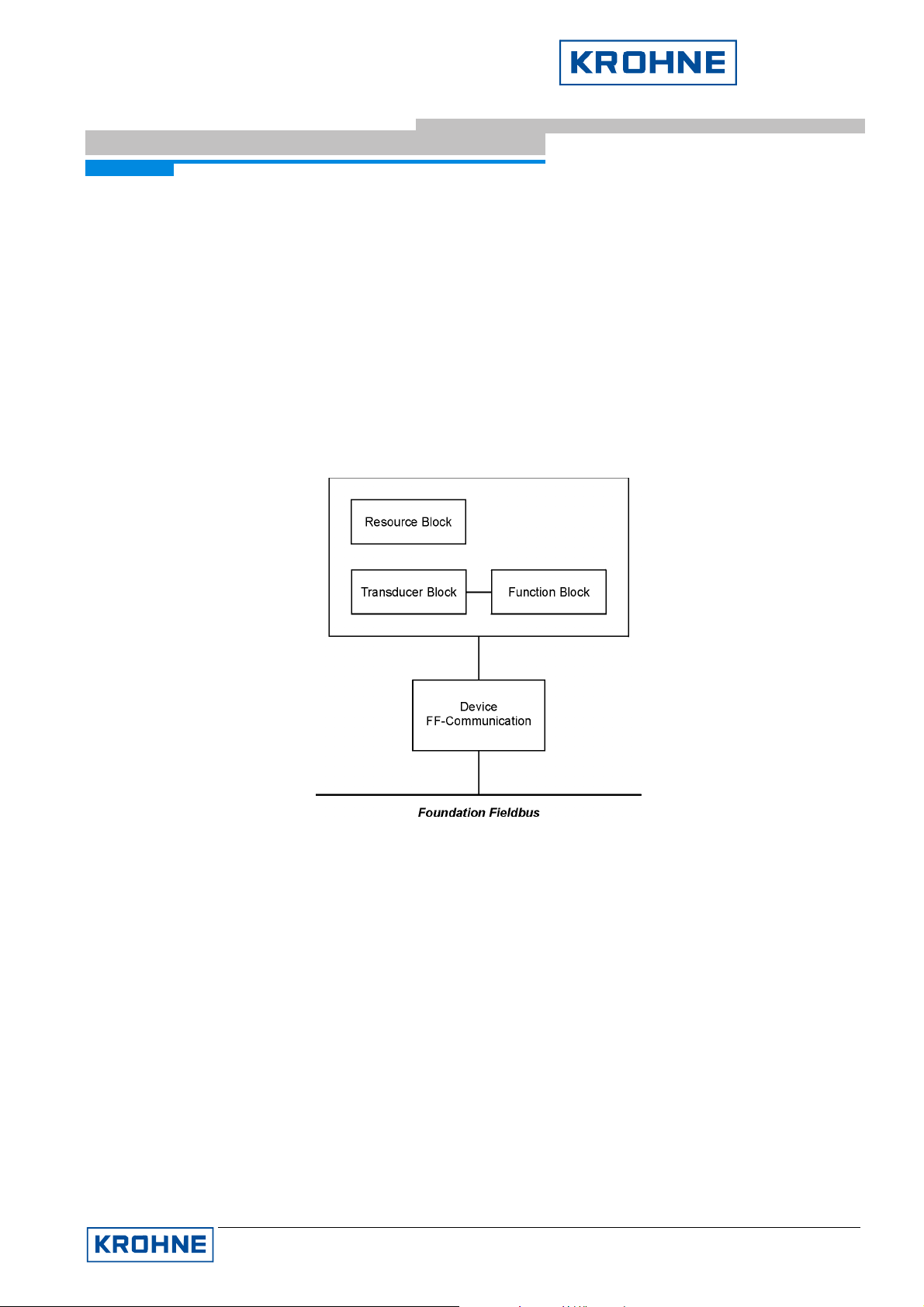
The different device functions are implemented in a block-based scheme within a User Application. In this block
scheme, a distinction is made between the following kinds of blocks (see Figure 1):
• Resource Block,
• Transducer Block(s) and
• Function Block(s).
Foundation Fieldbus Principles
Figure 1: Foundation Fieldbus block scheme
3.1 Resource Block
Each FF device possesses exactly one Resource Block describing the specific features of the fieldbus device.
The Resource Block is not related to any functional process of the device, but contains data that are specific for
the device (e.g. device name, serial number, supported features, etc).
In addition, the Resource Block provides dynamic diagnostic data giving information on the current state of the
hardware.
A basic set of Resource Block parameters is specified by Fieldbus Foundation (see FF-891, 3.1). This set can
be extended by additional manufacturer specific parameters (the IFC090-FF possesses the Foundation
specified parameters only).
KROHNE Messtechnik GmbH & Co. KG · Ludwig-Krohne-Str. 5 D-47058 Duisburg
Tel.: 0203-301 309 Fax: 0203-301389 · E-mail: krohne@krohne.de
Page 8

Supplementary Documentation Page 8 of 44
IFC090, IFC090 i with FF
IFC090 FF 01/2006
3.2 Transducer Block
Foundation Fieldbus Principles
Transducer Blocks represent the interface between the device specific hardware (i.e. input/output functions) and
the FF specified Function Block model. Since there might be multiple functions in a device (measurement
values, positioning functions, etc), an FF device can have several Transducer Blocks1.
They provide device specific information in terms of sensor/actuator functions (e.g. type of sensor, range of
process value, etc) and they make available the process values to the function blocks or provide the actuator
input values obtained from function blocks to the hardware respectively.
3.3 Function Blocks
The main functional behavior of the FF device is implemented in one or several Function Blocks. Depending on
the device type there are Input Blocks (e.g. flow device → Analog Input Block, Discrete Input, etc), Output
Blocks (e.g. valve → Discrete Input, etc), or Control Blocks (PID, etc). These blocks have input and/or output
parameters to be linked to other devices and to control systems by the Fieldbus.
1
Note: This does not imply that an FF device has to have several Transducer Blocks if it provides several
functions.
KROHNE Messtechnik GmbH & Co. KG · Ludwig-Krohne-Str. 5 D-47058 Duisburg
Tel.: 0203-301 309 Fax: 0203-301389 · E-mail: krohne@krohne.de
Page 9
Supplementary Documentation Page 9 of 44
IFC090, IFC090 i with FF
IFC090 FF 01/2006
4 IFC090-FF Block Description
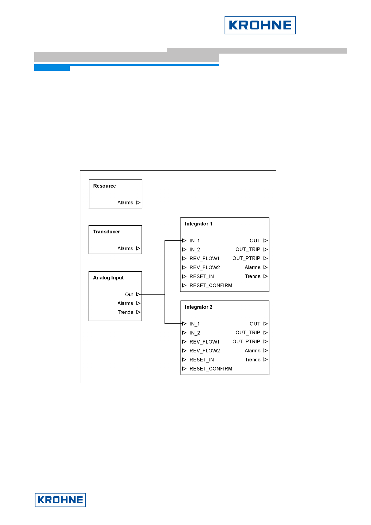
The IFC090-FF consists of the following blocks (see figure 2):
• 1 Resource Block,
• 1 Transducer Block (standard flow),
• 1 Analog Input Block (flow value) and
• 2 Integrator Blocks (1 for positive- and 1 for negative flow integration)
IFC090-FF Block Description
Figure 2: IFC090-FF block scheme
In the following, the different block parameters are described in detail.
KROHNE Messtechnik GmbH & Co. KG · Ludwig-Krohne-Str. 5 D-47058 Duisburg
Tel.: 0203-301 309 Fax: 0203-301389 · E-mail: krohne@krohne.de
Page 10

Supplementary Documentation Page 10 of 44
IFC090, IFC090 i with FF
IFC090 FF 01/2006
4.1 Resource Block
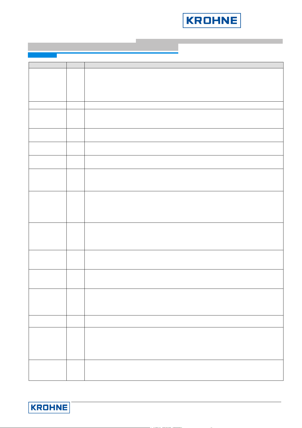
Table 1 lists the Resource Block parameters in alphabetical order (this list provides a description of the various
parameters only; for a more detailed description of how to configure these parameters: see chapter below.
IFC090-FF Block Description
Parameter Access
ACK_OPTION R/W
ALARM_SUM Mix
Description
Allows to enable automatic acknowledge of Resource Block alarms. The following
settings are valid for Resource Block:
Unack Alarm 1 (Discrete Alarm) clearing of soft write lock
Unack Alarm 8 (Block Alarm) block mode switches to Out of Service
If set, the respective alarm doesn’t have to be acknowledged when occurring.
see also: ALARM_SUM, WRITE_LOCK, WRITE_ALM
Display of process alarms. The current alarm is displayed in the current field and can
have the following values:
Discrete Alarm the soft write lock was cleared
Block Alarm block mode switches to Out of Service
The additional fields unacknowledged and unreported give respective information
about the current alarm state. The field disabled, which is the only writable field of this
parameter, can be used to disable these alarms.
see also: ACK_OPTION
ALERT_KEY R/W
ALERT_KEY parameter contains the identification number of the plant unit. It helps to
identify the location (plant unit) of an event. The handling of this parameter is up to the
control system or control person, respectively.
BLOCK_ALM R
Display of current block state. Field subcode gives information about the state current
errors. The following errors can occur:
Change in Simulation Jumper
Local Override
Device Fault State
Memory Failure
Lost Static Data
Lost NV Data
Power-up
Block was put Out of Service
The remaining fields give information about the state and the occurence of this alarm.
BLOCK_ERR R
Display of active block errors. The following errors are possible:
Power-up power supply of IFC090-FF was interrupted
Device needs Maintenance now fatal error of IFC090-FF hardware
Memory Failure memory of device has errors
Input Failure measurement value not o.k.
Other any other hardware problem
CLR_FSTATE R/W
Writing a Clear to this parameter will clear the device fault state if the field condition, if
any, has cleared.
NOTE:
This parameter is not supported!
Configuration Error
Out of Service block is in Out of Service mode
CONFIRM_TIME R/W
KROHNE Messtechnik GmbH & Co. KG · Ludwig-Krohne-Str. 5 D-47058 Duisburg
Tel.: 0203-301 309 Fax: 0203-301389 · E-mail: krohne@krohne.de
see also: FAULT_STATE
Time the resource waits for receipt confirmation of an earlier sent report, before trying
to send a new one. If zero (0), no retry will be performed.
Page 11
Supplementary Documentation Page 11 of 44
IFC090, IFC090 i with FF
IFC090 FF 01/2006
Parameter Access
CYCLE_SEL R/W
CYCLE_TYPE R
DD_RESOURCE R
DD_REV R
DEV_REV R
DEV_TYPE R
FAULT_STATE R
IFC090-FF Block Description
Description
Used to select the block execution method for this resource. The following methods
are available:
Scheduled
Completion of block execution
see also: CYCLE_TYPE
Identifies the block execution methods available for this resource.
It is possible to deliver devices which have the DD for its resource within the device.
This parameter assigns the tag where to find the DD in the resource. Since the
IFC090-FF doesn't come with a 'build-in' DD, this value is blank.
Revision associated with the DD of the resource – used by interface devices to locate
the DD file for the resource.
KROHNE revision number associated with this resource – used by interface devices to
locate the DD file for the resource.
KROHNE model number of the IFC090-FF – used by interface devices to locate the
DD file for the resource.
Condition set by loss of communication to an output block.
NOTE:
Since the IFC090-FF doesn’t have an output block, this parameter isn’t supported.
FEATURES R
Used to show supported resource block options. The following features are supported
by the IFC090-FF:
Soft Write Lock
see also: FEATURE_SEL
FEATURE_SEL R/W
Used to select supported features. The following features are selectable:
Soft Write Lock enable soft write locking of parameters
see also: FEATURE_SEL
FREE_TIME R
Available time for configuration of further blocks.
NOTE:
Since the IFC090 blocks are preconfigured, this value is always zero (0).
FREE_SPACE R
Available memory for configuration of further blocks.
NOTE:
Since the IFC090 blocks are preconfigured, this value is always zero (0).
GRANT_DENY R/W
Options for controlling access of host computer and local control panels to operating,
tuning and alarm parameters of the block.
NOTE:
This parameter is not supported by IFC090-FF
HARD_TYPES R
The type available input signal that is delivered by the Transducer Block and used as
Analog Input Block input parameter. For the IFC090-FF this is ‘Scalar Input’ (1).
ITK_VER R
Major revision number of the interoperability test case used in certifying this device as
interoperable.
Reports
Reports enable sending of alert reports
LIM_NOTIFY R/W
KROHNE Messtechnik GmbH & Co. KG · Ludwig-Krohne-Str. 5 D-47058 Duisburg
Tel.: 0203-301 309 Fax: 0203-301389 · E-mail: krohne@krohne.de
NOTE:
Due to an error, this value is ‘0’, but has to be ‘4’ (since the IFC090-FF is interoperable
with interoperability test case version 4).
Maximum number of unconfirmed alert notifies messages allowed. This number
always has to be less than MAX_NOTIFY.
see also: MAX_NOTIFY
Page 12

Supplementary Documentation Page 12 of 44
IFC090, IFC090 i with FF
IFC090 FF 01/2006
Parameter Access
MANUFAC_ID R
MAX_NOTIFY R
MEMORY_SIZE R
MIN_CYCLE_T R
MODE_BLK Mix
IFC090-FF Block Description
Description
Manufacturer identification number. For KROHNE devices this is always
00012C
= 30010 = KROHNE
16
Maximum number of unconfirmed notifies messages possible.
see also: LIM_NOTIFY
Available configuration memory in the empty resource.
NOTE:
This parameter is not supported by IFC090.
Time duration of the shortest cycle interval of which the IFC090 is capable. Within this
cycle all Function Blocks (1 Analog Input + 2 Integrators) have to be executed for one
time.
Display of the current (actual), desired (target), possible (permitted) and normal modes
of the Resource Block. By writing a permitted value to the target field, you can control
the execution modes of the block. The following block modes are allowed for the
IFC090-FF Resource Block:
Automatic Mode (AUTO)
In this mode, the complete resource is able to execute. All other blocks
(Transducer, Analog Input, Integrator) can switch to a mode different from Out of
Service)
Out of Service (OOS)
In this mode, the complete resource stops its execution. For the other blocks
it is not possible to switch to AUTO mode, unless the Resource Block does.
NOTE:
Under certain conditions (e.g. RS_STATE = ONLINE_LINKING) the Resource Block is
not capable of switching to AUTO mode.
see also: RS_STATE
NV_CYCLE_T R
Minimum time interval between two cycles of writing non-volatile parameters OUT, PV
and FIELD_VAL. Since these values are not saved, this value is always zero (0) which
means don’t save these parameters.
RESTART R/W
Allows a manual restart to be initiated. Several degrees of restart are possible:
RUN Setting for normal operation.
RESTART RESOURCE Warm start of the IFC090-FF.
RESTART WITH DEFAULTS Sets all FF parameters to their default values.
To be used with caution!
RESTART PROCESSOR Cold start of IFC090 measurement electronics
and warm start of FF process.
RS_STATE R
State of the function block application state machine. The following states are possible:
ONLINE Normal operation state: All defined links are established.
INITIALIZATION Initialization state: All alarms will be confirmed and
ONLINE-LINKING Link evaluation state: Wait until all links are established
STANDBY Out of Service state: Entered if mode of Resource Block is
SET_FSTATE R/W
Allows the Fault State conditions for output function blocks to be manually initiated by
setting to ‘Set’.
NOTE:
Since the IFC090-FF doesn’t have an output block, this parameter is not supported.
SHED_RCAS R/W
Time duration for the monitoring-cycle in which a function block in mode RCAS has to
answer on control system requests.
acknowledged.
OOS.
NOTE:
Since the IFC090-FF has no function block capable of switching to mode RCas, this
parameter is not supported.
KROHNE Messtechnik GmbH & Co. KG · Ludwig-Krohne-Str. 5 D-47058 Duisburg
Tel.: 0203-301 309 Fax: 0203-301389 · E-mail: krohne@krohne.de
Page 13

Supplementary Documentation Page 13 of 44
IFC090, IFC090 i with FF
IFC090 FF 01/2006
Parameter Access
SHED_ROUT R/W
Description
Time duration for the monitoring-cycle in which a function block in mode Rout has to
answer on control system requests.
NOTE:
Since the IFC090-FF has no function block capable of switching to mode Rout, this
parameter is not supported.
STRATEGY R/W
Parameter used to group a set of blocks. This is done by assigning the same
STRATEGY numerical value to all blocks belonging to one group.
NOTE:
This parameter is neither checked nor used by the function block application! It can be
used by control system to group blocks!
ST_REV R
Static data revision counter. ST_REV will be incremented if a static Resource Block
parameter has changed. By checking this parameter, control systems are able to
realize if a static parameter has changed its value without checking all static
parameters all the time.
TAG_DESC R/W
User description of the intended application of the block. The user is free in setting this
value. The only limitation is the length of 32 characters at maximum. It is not checked
by the application, but has informational character only.
TEST_RW R/W
Read/write test parameter. It is only used during Fieldbus Foundation interoperability
testing and has no meaning for normal operation!
UPDATE_EVT R
Alert generated by a change to static data. The subfields of this parameter give
detailed information about the changed static parameter, time of change and state of
the update event.
WRITE_ALM R
Alarm generated, if the parameter write lock is cleared.
see also: ACK_OPTION, WRITE_LOCK, WRITE_PRI
WRITE_LOCK R/W
If this parameter is set to ‘Locked’ (2) all writable parameters in all blocks are write
protected, with the exception of WRITE_LOCK itself. Dynamic data will continue to be
updated.
To disable the write protection, set this parameter to ‘Not Locked’ (1).
IFC090-FF Block Description
WRITE_PRI R/W
see also: ACK_OPTION, WRITE_ALM, WRITE_PRI
Priority of the alarm generated by clearing the WRITE_LOCK:
0 alarm isn't be evaluated
1 no notification to the control system in case of an write protection alarm
2 reserved for block alarms
3-7 write protection is send as user/operator note to the control system,
according to the given priority (3 = low and 7 = high)
8-15 write protection alarm is sent with the appropriate priority
(15 = high and 8 = low).
Table 1: Resource Block parameters
KROHNE Messtechnik GmbH & Co. KG · Ludwig-Krohne-Str. 5 D-47058 Duisburg
Tel.: 0203-301 309 Fax: 0203-301389 · E-mail: krohne@krohne.de
Page 14

Supplementary Documentation Page 14 of 44
IFC090, IFC090 i with FF
IFC090 FF 01/2006
4.2 Transducer Block
Table 2 lists the Transducer Block parameters in alphabetical order (this list gives a description of the various
parameters only; see chapter below. for a detailed description depicting how to configure these parameters):
IFC090-FF Block Description
Parameter Access
ALERT_KEY R/W
BLOCK_ALM R
BLOCK_ERR R
CAL_MIN_SPAN R
CAL_POINT_HI R/W
CAL_POINT_LO R/W
CAL_UNIT R/W
CAL_ZEROPOINT R/W
COLLECTION_DIRECTORY R
CYCLES_ZEROPOINT_CAL R/W
LIN_TYPE R/W
Description
Identification number of the plant unit. It helps to identify the location (plant
unit) of an event. The handling of this parameter is up to the control system
or control person, respectively.
Display of current block state. Field subcode gives information about the
state current errors. The following errors can occur:
Configuration Error
Block was put Out of Service
The remaining fields give information about the state and the occurrence of
this alarm.
Display of active block errors. The following errors are possible:
Out of Service block is in Out of Service mode
Device needs Maintenance now fatal error of IFC090-FF hardware
Minimum calibrated span value allowed.
Highest calibrated value. This value depends on the IFC090-FF pipe
diameter.
Lowers calibrated value. This is the absolute value of the lowest positive and
negative value, the device is capable of measuring, and it is constant to ‘0’.
Engineering units code index for the calibration values. This is always m3/s
(cubic meter per second).
Start zero point calibration by writing a value different from ‘0’.
NOTE:
Handle this parameter with caution, since a correct zero point calibration is
based some important conditions.
Directory that specifies the number, starting index, and DD2 item IDs of the
transducer block’s data collections. The first entry specifies the number of
data collections, and the remaining specifies the data collections.
Number of cycles to perform if a zero point calibration is started. Valid values
are in between 0 and 2000.
Linearization type used to describe the behavior of the sensor output. The
IFC090-FF has a linearization type of ‘linear with input’.
2
DD = Device Description
KROHNE Messtechnik GmbH & Co. KG · Ludwig-Krohne-Str. 5 D-47058 Duisburg
Tel.: 0203-301 309 Fax: 0203-301389 · E-mail: krohne@krohne.de
Page 15

Supplementary Documentation Page 15 of 44
IFC090, IFC090 i with FF
IFC090 FF 01/2006
Parameter Access
MODE_BLK Mix
Description
Display of the current (actual), desired (target), possible (permitted) and
normal modes of the Transducer Block. By writing a permitted value to the
target field, you can control the execution modes of the block. The following
block modes are allowed for the IFC090-FF Transducer Block:
Automatic Mode (AUTO)
In this mode, the transducer performs an automatic measurement update
and delivers it via its channels to connected input blocks (normally, the
integrated Analog Input Block)
Manual (MAN)
Different from the AUTO mode, the block doesn’t perform an automatic
delivery of valid measurement values, but freezes its primary value to the
last one obtained in Auto mode. The PRIMARY_VALUE status switches
to Uncertain:NonSpecific:Constant.
Out of Service (OOS)
In this mode, the transducer stops measurement update and sets the
status of the measured value (PRIMARY_VALUE) to
BadOutOfService:NotLimited.
NOTE:
If the Resource Block is in mode Out of Service, also the block will remain in
this mode.
IFC090-FF Block Description
PRIMARY_VALUE R
PRIMARY_VALUE_RANGE R
The measured value and status available to the Function Blocks.
The high and low range limit values, the engineering units code and the
number of digits to the right of the decimal point to be used to display the
PRIMARY_VALUE.
PRIMARY_VALUE_TYPE R/W
Type of sensor. The IFC090-FF is of type ‘volumetric flow’ (101).
NOTE:
Even though this parameter is writable, it does not accept a value different
from ‘volumetric flow’ (101).
SECONDARY_VALUE R
Normally, the secondary value, is related to the sensor. Since the IFC090-FF
has no secondary value, this is fixed to status Bad:NonSpecific:NotLimited
with value 0.0.
SECONDARY_VALUE_UNIT R/W
Normally the units to be used for the SECONDARY_VALUE. Since the
IFC090-FF has no secondary value, this is fixed to the unit of the primary
value.
SENSOR_CAL_DATE R/W
Date of last sensor calibration. If this is set ‘01/01/84 00:00:00’ it means that
the last calibration was that after production of device.
SENSOR_CAL_LOC R/W
SENSOR_CAL_METHOD R/W
Location of last sensor calibration.
Method of last sensor calibration. In the context of the ISO defined standard
method of calibrations, KROHNE performed a ‘factory trim standard
calibration’.
SENSOR_CAL_WHO R/W
SENSOR_RANGE R
Name of the person responsible for the last calibration.
The high and low range limit values, the engineering units code, and the
number of digits to the right of the decimal point for the sensor. These values
are equal to the one given for PRIMARY_VALUE_RANGE.
SENSOR_SN R
Sensor serial number. Must be the same as on the nameplate of the device’s
housing.
SENSOR_TYPE R/W
Type of sensor. For IFC090-FF this is fixed: ‘Electromagnetic’ (102)
NOTE:
Even though this parameter is writable, it does not accept a value different
from ‘Electromagnetic’ (102).
KROHNE Messtechnik GmbH & Co. KG · Ludwig-Krohne-Str. 5 D-47058 Duisburg
Tel.: 0203-301 309 Fax: 0203-301389 · E-mail: krohne@krohne.de
Page 16

Supplementary Documentation Page 16 of 44
IFC090, IFC090 i with FF
IFC090 FF 01/2006
Parameter Access
ST_REV R
Description
Static data revision counter. ST_REV will be incremented if a static
Transducer Block parameter has changed. By checking this parameter,
control systems are able to realize if a static parameter has changed its
value without checking all static parameters all the time.
IFC090-FF Block Description
STRATEGY R/W
Parameter used to group a set of blocks. This is done by assigning all blocks
belonging to one group the same STRATEGY numerical value.
NOTE:
This parameter is neither checked nor used by the function block application!
It can be used by control system to group blocks!
TAG_DESC R/W
User description of the intended application of the block. The user is free in
setting this value. The only limitation is the length of 32 characters at
maximum. It is not checked by the application, but has informational
character only.
TRANSDUCER_DIRECTORY R
Directory that specifies the number and starting indices of the transducers in
the transducer blocks.
Since the IFC090-FF possesses only one transducer, the directory consists
of one entry only (1 = number of transducers, 711 = starting index of the only
transducer).
UPDATE_EVENT R
Alert generated by a change to static data. The subfields of this parameter
give detailed information about the changed static parameter, time of change
and state of the update event.
XD_ERROR R
Error code that is specific to the sensor hardware. If a profoundly hardware
error is existent, this parameter shows the error ‘Electronics failure’ (20).
4.3 Analog Input Block (Flow)
Table 3 lists the Analog Input Block parameters in alphabetical order (this list gives a description of the various
parameters only; see chapter below for a detailed description of how to configure these parameters):
Parameter Access
ACK_OPTION R/W
ALARM_HYS R/W
Description
Allows to enable automatic acknowledge of Analog Input Block alarms. The
following settings are valid for Resource Block:
Unack Alarm 1 (Discrete Alarm) clearing of soft write lock
Unack Alarm 2 (High High Alarm) OUT value reaches the HI_HI_LIM
Unack Alarm 3 (High Alarm) OUT value reaches the HI_LIM
Unack Alarm 4 (Low Low Alarm) OUT value reaches the LOW_LOW_LIM
Unack Alarm 5 (Low Alarm) OUT value reaches the LO_LIM
Unack Alarm 8 (Block Alarm) block mode switches to Out of Service
If set, the respective alarm don’t has to be acknowledged on occurence
see also: ALARM_SUM
Amount the OUT value must return within the alarm limits before the alarm
condition (HI_HI_ALM; HI_ALM, LO_ALM, LOW_LOW_ALM) clears.
Alarm Hysteresis is expressed as percent of the OUT_SCALE span and is
set 0.5% by default.
KROHNE Messtechnik GmbH & Co. KG · Ludwig-Krohne-Str. 5 D-47058 Duisburg
Tel.: 0203-301 309 Fax: 0203-301389 · E-mail: krohne@krohne.de
Page 17

Supplementary Documentation Page 17 of 44
IFC090, IFC090 i with FF
IFC090 FF 01/2006
Parameter Access
ßALARM_SUM R
Description
Display of process alarms. The current alarm is displayed in the current field
an can have the following values:
IFC090-FF Block Description
Discrete Alarm the soft write lock was cleared
HiHi Alarm the high limit alarm is active
Hi Alarm the high limit advance alarm is active
Lo Alarm the low limit advance alarm is active
LoLo Alarm the low limit alarm is active
Block Alarm block mode switches to Out of Service
The additional fields unacknowledged and unreported give respective
information about the current alarm state. The field disabled, which is the
only writable field of this parameter, can be used to disable these alarms.
see also: ACK_OPTION
ALERT_KEY R/W
ALERT_KEY parameter contains the identification number of the plant unit. It
helps to identify the location (plant unit) of an event. The handling of this
parameter is up to the control system or control person, respectively.
BLOCK_ALM R
Display of current block state. Field subcode gives information about the
state current errors. The following errors can occur:
Configuration Error
Block was put Out of Service
The remaining fields give information about the state and the occurrence of
this alarm.
BLOCK_ERR R
Display of active block errors. The following errors are possible:
Out of Service block is in Out of Service mode
Input Failure SIMULATE.status is Bad:NonSpecific
Simulate Active SIMULATE.enable = yes
Block Configuration Error channel unit != XD_SCALE.unit, or
CHANNEL != 1, or L_TYPE is uninitalized
CHANNEL R/W
Number of the transducer’s logical hardware channel that is connected to
this Analog Input block. The only valid value is ‘1’ (since the Transducer has
only one hardware channel). Every other value would cause an ‘Block
Configuration Error’ which is displayed in BLOCK_ERR.
The default value is ‘0’.
FIELD_VAL R
Raw value of the field device in percent of the PV range, with a status
reflecting the Transducer condition, before characterization (L_TYPE) or
filtering (PV_FTIME). See 5.3.3 for details.
GRANT_DENY R/W
Options for controlling access of host computer and local control panels to
operating, tuning and alarm parameters of the block.
NOTE:
This parameter is not supported by IFC090-FF.
HI_ALM R
With subject to the setting of HI_PRI, HI_ALM shows details about the high
alarm as acknowledge state and time stamp. See HI_PRI for details.
see also: HI_PRI, HI_LIM
HI_HI_ALM R
With subject to the setting of HI_HI_PRI, HI_HI_ALM shows details about the
high high alarm as acknowledge state and time stamp. See HI_HI_PRI for
details.
see also: HI_HI_PRI, HI_HI_LIM
HI_HI_LIM R/W
The limit value in engineering units as of the HI_HI_ALM is active (with
subject to HI_HI_PRI).
see also: HI_HI_PRI, HI_HI_LAM
KROHNE Messtechnik GmbH & Co. KG · Ludwig-Krohne-Str. 5 D-47058 Duisburg
Tel.: 0203-301 309 Fax: 0203-301389 · E-mail: krohne@krohne.de
Page 18

Supplementary Documentation Page 18 of 44
IFC090, IFC090 i with FF
IFC090 FF 01/2006
Parameter Access
HI_HI_PRI R/W
Description
Priority of the high high alarm that specifies the behavior if OUT reaches
HI_HI_LIM. The following values are valid:
0 exceeding of high high limit isn’t been evaluated
1 exceeding of high high limit is been evaluated, but
acknowledgement isn’t necessary
2-7 exceeding of high high limit is been evaluated and reported
according to the given priority (2 = low priority, 7 = high
priority).
Status of OUT changes to Good(NC):
UnackAdvisoryAlarmHighLimited.
8-15 exceeding of high high limit is been evaluated and reported
Status of OUT changes to Good(NC):
UnackCriticalAlarmHighLimited.
IFC090-FF Block Description
HI_LIM R/W
The limit value in engineering units as of the HI_ALM is active (with subject
to HI_PRI).
see also: HI_PRI, HI_LIM
HI_PRI R/W
Priority of the high alarm that specifies the behavior if OUT reaches HI_LIM.
The following values are valid:
0 exceeding of high limit isn’t been evaluated
1 exceeding of high limit is been evaluated, but
acknowledgement isn’t necessary
2-7 exceeding of high limit is been evaluated and reported
according to the given priority (2 = low priority, 7 = high
priority).
Status of OUT changes to
Good(NC):UnackAdvisoryAlarmHighLimited.
8-16 exceeding of high limit is been evaluated and reported
Status of OUT changes to
Good(NC):UnackCriticalAlarmHighLimited.
IO_OPTS R/W
Options which the user may select to alter input and output processing of the
Analog Input Block. The following option is supported by this block:
Low cutoff The Analog Input low cutoff algorithm is enabled, i.e. if PV is
less than LOW_CUT, PV is set to ‘0.0’
according to the given priority (2 = low priority, 7 = high
priority).
according to the given priority (2 = low priority, 7 = high
priority).
see also: LOW_CUT
L_TYPE R/W
Determines how the values, passed by the Transducer Block to the Analog
Input Block, may be used. The following settings are valid:
Direct values are used directly
Indirect values are in different units and must be converted
Indirect square root values are in different units and must be converted
with square root.
The conversion in case of ‘Indirect’ and ‘Indirect square root’ is
determined by parameters XD_SCALE and OUT_SCALE (see for
details).
see also: XD:SCALE, OUT_SCALE
LO_ALM R
With subject to the setting of LO_PRI, LO_ALM shows details about the high
alarm as acknowledge state and time stamp. See LO_PRI for details.
see also: LO_PRI, LO_LIM
KROHNE Messtechnik GmbH & Co. KG · Ludwig-Krohne-Str. 5 D-47058 Duisburg
Tel.: 0203-301 309 Fax: 0203-301389 · E-mail: krohne@krohne.de
Page 19

Supplementary Documentation Page 19 of 44
IFC090, IFC090 i with FF
IFC090 FF 01/2006
Parameter Access
LO_LIM R/W
Description
The limit value in engineering units as of the LO_ALM is active (with subject
to LO_PRI).
see also: LO_PRI, LO_LAM
IFC090-FF Block Description
LO_LO_ALM R
With subject to the setting of LO_LO_PRI, LO_LO_ALM shows details about
the high alarm as acknowledge state and time stamp. See LO_LO_PRI for
details.
see also: LO_LO_PRI, LO_LO_LIM
LO_LO_LIM R/W
The limit value in engineering units as of the LO_LO_ALM is active (with
subject to LO_LO_PRI).
see also: LO_LO_PRI, LO_LO_LAM
LO_LO_PRI R/W
Priority of the low alarm that specifies the behavior if OUT reaches
LO_LO_LIM. The following values are valid:
0 exceeding of low limit isn’t been evaluated
1 exceeding of low limit is been evaluated, but
acknowledgement isn’t necessary
2-7 exceeding of low limit is been evaluted and reported
according to the given priority (2 = low priority, 7 = high
priority).
Status of OUT changes to
Good(NC):UnackAdvisoryAlarm:LowLimited.
8-17 exceeding of low limit is been evaluated and reported
Status of OUT changes to Good(NC):
UnackCriticalAlarm:LowLimited.
LO_PRI R/W
Priority of the low low alarm that specifies the behavior if OUT reaches
LO_LIM. The following values are valid:
0 exceeding of low low limit isn’t been evaluated
1 exceeding of low low limit is been evaluated, but
acknowledgement isn’t necessary
2-7 exceeding of low low limit is been evaluted and reported
according to the given priority (2 = low priority, 7 = high
priority).
Status of OUT changes to
Good(NC):UnackAdvisoryAlarm:LowLimited.
8-18 exceeding of low low limit is been evaluated and reported
Status of OUT changes to
Good(NC):UnackCriticalAlarm:LowLimited.
LOW_CUT R/W
Limit used if option ‘Low cutoff’ is set (see IO_OPTS for details). A value of
zero percent of scale is used in block processing if the transducer value falls
below the LOW_CUT limit. This feature may be used to eliminate noise near
zero for a flow sensor.
according to the given priority (2 = low priority, 7 = high
priority).
according to the given priority (2 = low priority, 7 = high
priority).
KROHNE Messtechnik GmbH & Co. KG · Ludwig-Krohne-Str. 5 D-47058 Duisburg
Tel.: 0203-301 309 Fax: 0203-301389 · E-mail: krohne@krohne.de
Page 20

Supplementary Documentation Page 20 of 44
IFC090, IFC090 i with FF
IFC090 FF 01/2006
Parameter Access
MODE_BLK Mix
Description
Display of the current (actual), desired (target), possible (permitted) and
normal modes of the Analog Input Block. By writing a permitted value to the
target field, you can control the execution modes of the block. The following
block modes are allowed for the IFC090-FF Analog Input Block:
Automatic Mode (AUTO)
In this mode, the Analog Input Block performs its functional computations
in accordance with its configuration automatically. Measurement value
deliverance and alarm handling are active.
Manual (MAN)
In difference to AUTO mode, the block doesn’t perform an automatic
deliverance of valid measurement values, but freezes the measurement
to the last one obtained in Auto mode. The OUT status limit switches to
constant. In this mode it is possible to write to the OUT value an arbitrary
value to test blocks that use this OUT value as input. The alarm model
works in the same way as in Auto mode.
Out of Service (OOS)
In this mode, the Analog Input Block stops its execution. No valid
measurement value will be delivered, what can be seen at the status of
OUT (Bad:OutOfService:NotLimited).
IFC090-FF Block Description
OUT R/W
The primary analog value and status calculated as a result of executing the
block.
In Auto mode of this block, the value and its status is automatically
calculated on the base of the channel value obtained from the Transducer
Block and calculation methods of the Analog Input Block. In Man mode it is
possible to write to this value to specify a known, given value that can be
used to test the correct operation of other downstream function blocks.
OUT_SCALE R/W
Together with parameter XD_SCALE, OUT_SCALE is one of the two main
scaling parameters. It can’t be seen isolated. These two parameters specify
a mapping function from the channel value obtained from the. See 5.3.2 for
details.
PV R
Value and status of the process value with same unit as OUT_SCALE. PV is
the result after performing the linearization (see L_TYPE), the low cutoff (see
LOW_CUT, IO_OPTS) and the filtering (see PV_FTIME).
PV_FTIME R/W
SIMULATE R/W
Time constant of the single exponential filter for the PV in seconds.
Normally, SIMULATE is used to perform a channel value and status
simulation, i.e. instead of using the channel value obtained from the
Transducer Block, the user would be able to simulate a distinct (constant)
value and status as it comes from the Transducer. This is intensively used
while interoperability testing at the Fieldbus Foundation. Since it has no
practical use, this parameter isn’t supported by the IFC090-FF.
ST_REV R
Static data revision counter. ST_REV will be incremented if a static Analog
Input Block parameter has changed. By checking this parameter, control
systems are able to realize if a static parameter has changed its value
without checking all static parameters all the time.
KROHNE Messtechnik GmbH & Co. KG · Ludwig-Krohne-Str. 5 D-47058 Duisburg
Tel.: 0203-301 309 Fax: 0203-301389 · E-mail: krohne@krohne.de
Page 21

Supplementary Documentation Page 21 of 44
IFC090, IFC090 i with FF
IFC090 FF 01/2006
Parameter Access
STATUS_OPTS R/W
Description
STATUS_OPTS specifies how the OUT value status has to be set. If no
status option is selected, the channel value status is used. Otherwise, the
OUT status is set subject to the following possible status options:
Uncertain if Limited Set the OUT status to Uncertain if if the
BAD if Limited Set the OUT status to BAD if the channel
Uncertain if Man mode Set the OUT status to Uncertain if the actual
IFC090-FF Block Description
STRATEGY R/W
Parameter used to group a set of blocks. This is done by assigning all blocks
belonging to one group the same STRATEGY numerical value.
NOTE:
This parameter is neither checked nor used by the function block application!
It can be used by control system to group blocks!
TAG_DESC R/W
User description of the intended application of the block. The user is free in
setting this value. The only limitation is the length of 32 characters at
maximum. It is not checked by the application, but has informational
character only.
UPDATE_EVT R
Alert generated by a change to static data. The subfields of this parameter
give detailed information about the changed static parameter, time of change
and state of the update event.
XD_SCALE R/W
Together with parameter OUT_SCALE, XD_SCALE is one of the two main
scaling parameters. It can’t be seen isolated. These two parameters specify
a mapping function from the channel value obtained from the. See 5.3.2 for
details.
NOTE:
Since the Transducer Block parameter PRIMARY_VALUE has a fixed, not
changeable unit, and the unit of XD_SCALE has to match meet the unit of
this parameter. It is possible to change the unit of XD_SCALE but this would
result in a BLOCK_ERR of ‘Block Configuration Error’ and associated OUT
value status.
Table 3: Analog Input Block parameters
channel value is limited.
value is limited.
mode of the Analog Input Block is Man.
Otherwise the channel status would be
used with constant limit.
KROHNE Messtechnik GmbH & Co. KG · Ludwig-Krohne-Str. 5 D-47058 Duisburg
Tel.: 0203-301 309 Fax: 0203-301389 · E-mail: krohne@krohne.de
Page 22
Supplementary Documentation Page 22 of 44
IFC090, IFC090 i with FF
IFC090 FF 01/2006
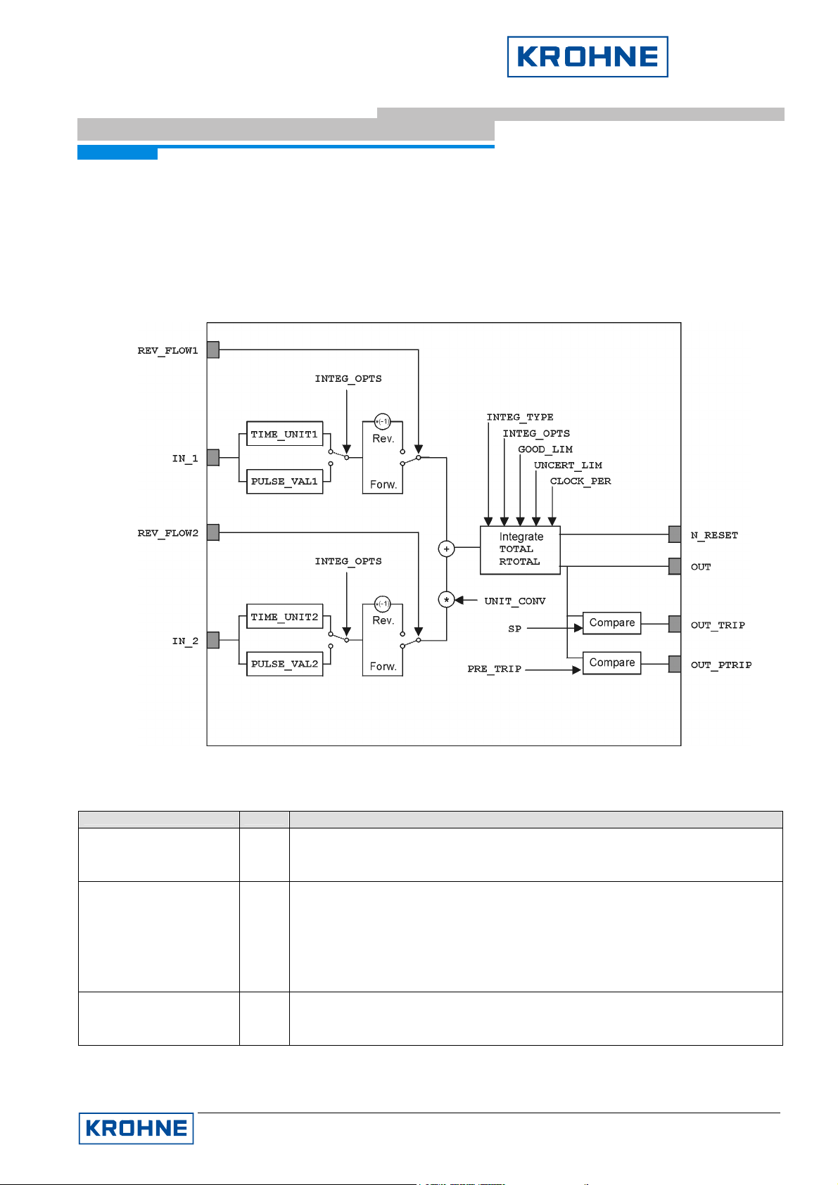
4.4 Integrator Blocks 1 and 2 (Flow(+)- and Flow(-)-Totalizer)
Table 4 lists the Integrator Blocks parameters in alphabetical order (this list gives a description of the various
parameters only; see chapter below for a detailed description of how to configure these parameters). The
descriptions are valid for both Integrators, ‘Flow(+) Totalizer’ and ‘Flow(-) Totalizer’ unless expressively pointed
out:
IFC090-FF Block Description
Figure 2: IFC090-FF Integrator Block
Parameter Access
ALERT_KEY R/W
Description
ALERT_KEY parameter contains the identification number of the plant unit. It
helps to identify the location (plant unit) of an event. The handling of this
parameter is up to the control system or control person, respectively.
BLOCK_ALM R
Display of current block state. Field subcode gives information about the state
current errors. The following errors can occur:
Configuration Error
Block was put Out of Service
The remaining fields give information about the state and the occurrence of
this alarm.
BLOCK_ERR R
Display of active block errors. The following errors are possible:
Out of Service block is in Out of Service mode
Memory Failure memory of device has errors
KROHNE Messtechnik GmbH & Co. KG · Ludwig-Krohne-Str. 5 D-47058 Duisburg
Tel.: 0203-301 309 Fax: 0203-301389 · E-mail: krohne@krohne.de
Page 23

Supplementary Documentation Page 23 of 44
IFC090, IFC090 i with FF
IFC090 FF 01/2006
Parameter Access
CLOCK_PER R/W
Description
CLOCK_PER specifies the time after which the Integrator OUT value should
be reset, if parameter INTEG_TYPE is set to ‘Periodic’.
see also: INTEG_TYPE
IFC090-FF Block Description
GOOD_LIM R/W
GOOD_LIM specifies the limit for Good status of parameter OUT. If the
percentage of Good input gets below this limit (and above UNCERT_LIM),
the status of OUT turns from Good to Uncertain (unless GOOD_LIM equals
UNCERT_LIM).
see also: UNCERT_LIM
GRANT_DENY R/W
Options for controlling access of host computer and local control panels to
operating, tuning and alarm parameters of the block.
NOTE:
This parameter is not supported by IFC090-FF
IN_1 R
Primary block input with status coming (normally) from another block’s output
parameter.
see also: IN_2
IN_2 R
Secondary block input with status, coming (normally) from another block’s
output parameter.
see_also: IN_1
INTEG_OPTS R/W
INTEG_OPTS is to be used to specify several integration options as type of
input used in each input, flow direction to be considered in the totalization,
status to be considered in the totalization and if the totalizatiion residue shall
be used in the next batch after a reset. The following INTEG_OPTS are
possible:
Input 1 accumulate IN_1 is used as pulse (otherwise as rate)
Input 2 accumulate IN_2 is used as pulse (otherwise as rate)
Flow forward only positive net flow will be taken into account
Flow reverse only negative net flow will be taken into account
Use Uncertain IN_1 and IN_2 input will be taken into account
Use BAD Input IN_1 or IN_2 with BAD status will be interpreted
Carry integration after a reset starts with the init value,
Add zero if Bad If one of the input (IN_1 or IN_2) statuses are
Confirm reset after a manual reset of totalization, the next
Generate reset event in case of reset (automatic or manual), an event
for totalization (NOTE: default settig for Integrator
1)
for totalization (NOTE: default settig for Integrator
2)
even if their states are Uncertain (otherwise the
value with the last Good status will be taken)
as Good (NOTE: only the status is interpreted as
Good, the value isn’t used for totalization, but the
good one, i.e. RTOTAL isn’t affected with this
setting.
but with the residual after the trip value.
BAD, not the last Good value is used for
totalization, but zero (0).
manual reset must be preceded by a reset
confirmation by the control system.
notification will be sent to the control system.
see also: INTEG_TYPE
KROHNE Messtechnik GmbH & Co. KG · Ludwig-Krohne-Str. 5 D-47058 Duisburg
Tel.: 0203-301 309 Fax: 0203-301389 · E-mail: krohne@krohne.de
Page 24

Supplementary Documentation Page 24 of 44
IFC090, IFC090 i with FF
IFC090 FF 01/2006
Parameter Access
INTEG_TYPE R/W
Description
INTEG_TYPE defines the type of counting (up or down) and the type of
resetting the totalization. The following types are available:
Up auto Totalization starts with 0.0 and counts up with
Up demand Totalization starts with 0.0 and counts up. A reset
Down auto Totalization starts with TOTAL_SP and counts
Down demand Totalization starts with TOTAL_SP and counts
Periodic Totalization starts with 0.0 and counts up. A
Demand Totalization starts with 0.0 and counts up. To
Periodic & Demand Same as ‘Periodic’ with the exception that
IFC090-FF Block Description
automatic reset if TOTAL_SP is reached.
isn’t performed except either a reset is initiated by
RESET_IN or OP_CMD_INT.
down with automatic reset if 0.0 is reached.
down. A reset isn’t performed except a reset is
initiated either by RESET_IN or OP_CMD_INT.
automatic reset is performed in accordance to the
time given in parameter CLOCK_PER (NOTE:
RESET_IN and OP_CMD_INT resets are disabled
and would produce a ‘Wrong Mode For Request’
error).
perform a reset, the operator has to write ‘reset’ to
parameter OP_CMD_INT.
RESET_IN and OP_CMD_INT resets are possible.
see also: RESET_IN, OP_CMD_INT, N_RESET
MODE_BLK Mix
Display of the current (actual), desired (target), possible (permitted) and
normal modes of the Integrator Block. By writing a permitted value to the
target field, you can control the execution modes of the block. The following
block modes are allowed for the IFC090-FF Integrator Block:
Automatic Mode (AUTO)
In this mode, the Integrator Block performs its functional computations in
accordance with its configuration automatically. Totalization is active.
Manual (MAN)
In difference to AUTO mode, the block doesn’t perform an automatic
totalization, but freezes the totalization value to the last one obtained in
Auto mode. The OUT status limits switches to constant. In this mode it is
possible to write to the OUT value an arbitrary value to test blocks that
use this OUT value as input.
Out of Service (OOS)
In this mode, the Integrator Block stops its execution. No totalization is
performed, what can be seen at the status of OUT
(Bad:OutOfService:NotLimited).
N_RESET R
Counts the number of totalization resets. The counter provides verification
that the totalization don’t has been reset since it was last checked.
OP_CMD_INT R/W
Setting this parameter to reset performs a totalization reset according to the
chosen integration type (see parameter INTEG_TYPE for details).
see also: INTEG_TYPE
OUT R/W
The totalization value and status calculated as a result of executing the block.
In Auto mode of this block, the value and its status is automatically calculated
on the base of the calculation methods of the Integrator Block. In Man mode it
is possible to write to this value to specify a known, given value that can be
used to test the correct operation of other downstream function blocks.
KROHNE Messtechnik GmbH & Co. KG · Ludwig-Krohne-Str. 5 D-47058 Duisburg
Tel.: 0203-301 309 Fax: 0203-301389 · E-mail: krohne@krohne.de
Page 25

Supplementary Documentation Page 25 of 44
IFC090, IFC090 i with FF
IFC090 FF 01/2006
Parameter Access
OUT_PTRIP R/W
Description
Second discrete output. OUT_PTRIP can be used within a control system, to
get a discrete indication, that a specified value of totalization is reached (e.g.
as indication to start closing a valve). The specified value to reach can be set
in parameter PRE_TRIP.
NOTE:
If the totalization reaches PRE_TRIP, OUT_PTRIP is set to 255 (0xFF).
see also: PRE_TRIP, OUT_TRIP
IFC090-FF Block Description
OUT_RANGE R
Display scaling of the output OUT. It has no effect on the block and is used
by downstream blocks or control system to get the unit of the totalization.
OUT_TRIP R/W
Second discrete output. OUT_TRIP can be used within a control system, to
get a discrete indication, that the specified value of totalization for resetting
(automatic reset is selected) is reached. The specified value to reach can be
set in parameter TOTAL_SP.
see also: TOTAL_SP, OUT_PTRIP
OUTAGE_LIM R/W
PCT_INCL R
Maximum tolerable time for power failure. Not used by the IFC090-FF
Percentage of BAD and Uncertain net flow values used in conjunction with
GOOD_LIM and UNCERT_LIM to determine the status of the output value
OUT. It is calculated by the following equation:
PCT_INCL = 100 * (1 - (rtotal / atotal),
where rtotal is the portion of BAD and Uncertain net flows and atotal the
absolute value of all net flows.
see also: GOOD_LIM, UNCERT_LIM
PRE_TRIP R/W
When integration is counting up (see INTEG_TYPE) and the totalization
value equals or exceeds (TOTAL_SP - PRE_TRIP) then the discrete output
OUT_PTRIP is set to 0xFF.
If counting down and the value of OUT is equal to or less than PRE_TRIP,
the discrete output OUT_PTRIP is set to 0xFF.
see also: OUT_PTRIP
PULSE_VAL1 R/W
PULSE_VAL1 specifies the factor by witch IN_1 is to be multiplied if IN_1 is
used as input of accumulated pulses (i.e. ‘Input 1 accumulate’ is set in
INTEG_OPTS). In this respect, IN_1 will be converted according to the
following equation:
IN_1 = IN_1 * PULSE_VAL1
PULSE_VAL2 R/W
PULSE_VAL2 specifies the factor by witch IN_2 is to be multiplied if IN_2 is
used as input of accumulated pulses (i.e. ‘Input 1 accumulate’ is set in
INTEG_OPTS). In this respect, IN_2 will be converted according to the
following equation:
IN_2 = IN_2 * PULSE_VAL2
RESET_CONFIRM R/W
RESET_CONFIRM can be used by control systems to confirm a reset event
report if ‘Confirm reset’ is set in INTEG_OPTS.
RESET_IN R/W
RESET_IN can be used by control systems to reset the totalization by an
external signal. By setting 'value' to 'Reset' (0x01) and a status of
GoodNC:NS:NL, the integrator will be reset as if OP_CMD_INT was set to
'Reset'.
see also: OP_CMD_INT, INTEG_TYPE
KROHNE Messtechnik GmbH & Co. KG · Ludwig-Krohne-Str. 5 D-47058 Duisburg
Tel.: 0203-301 309 Fax: 0203-301389 · E-mail: krohne@krohne.de
Page 26

Supplementary Documentation Page 26 of 44
IFC090, IFC090 i with FF
IFC090 FF 01/2006
Parameter Access
REV_FLOW1 R/W
Description
REV_FLOW1 can be used to indicate a reverse IN_1 flow. If IN_1 flow is
positive (i.e. forward flow), setting this parameter to a value not equal to
‘Discrete state 0’ (0), will result in the same but negative value (i.e.
multiplication by (-1)).
NOTE:
If ‘Forward flow’ is selected in INTEG_OPTS (which is the default for
Integrator Block 1) the resulting net flow will always be 0.0 for negative net
flows! If ‘Reverse flow’ is selected in INTEG_OPTS (which is the default for
Integrator 2) the resulting net flow will always be 0.0 for positive flows!
IFC090-FF Block Description
REV_FLOW2 R/W
REV_FLOW2 can be used to indicate a reverse IN_2 flow . If IN_2 flow is
positive (i.e. forward flow), setting this parameter to a value not equal to
‘Discrete state 0’ (0), will result in the same but negative value (i.e.
multiplication by (-1)).
NOTE:
If ‘Forward flow’ is selected in INTEG_OPTS (which is the default for
Integrator Block 1) the resulting net flow will always be 0.0 for negative net
flows! If ‘Reverse flow’ is selected in INTEG_OPTS (which is the default for
Integrator 2) the resulting net flow will always be 0.0 for positive flows!
RTOTAL R
RTOTAL stands for ‘rejects total’ and integrates the net flow values with
status BAD (if ‘Use BAD’ is not set in INTEG_OPTS) and Uncertain (if ‘Use
Uncertain’ is not set on INTEG_OPTS) and is used to calculate the parameter
PCL_INCL (see PCL_INCL for details).
see also: PCL_INCL
SRTOTAL R
SRTOTAL stands for 'snapshot RTOTAL' and displays the value of RTOTAL
just before the last reset (if one has happened, inspect N_RESET to see if
one has happen). The initial value is set to zero (0).
SSP R
SSP stands for 'snapshot TOTAL_SP' and displays the value of TOTAL_SP
just before the last reset (if one has happened). The initial value is set to zero
(0).
ST_REV R
Static data revision counter. ST_REV will be incremented if a static Integrator
Block parameter has changed. By checking this parameter, control systems
are able to realize if a static parameter has changed its value without
checking all static parameters all the time.
STATUS_OPTS R/W
STATUS_OPTS specifies how the OUT, OUT_TRIP and OUT_PTRIP status
has to be set. If no status option is selected, the status is the result from the
block’s operation. Otherwise, the status is set subject to the following
possible status option:
Uncertain if Man mode Set the OUT, OUT_TRIP and OUT_PTRIP status to
STOTAL R
STOTAL stands for 'snapshot TOTAL' and displays the value of the
totalization (= OUT) just before a reset (if one has happened). The initial
value is set to zero (0).
STRATEGY R/W
Parameter used to group a set of blocks. This is done by assigning all blocks
belonging to one group the same STRATEGY numerical value.
NOTE:
This parameter is neither checked nor used by the function block application!
It can be used by control system to group blocks!
TAG_DESC R/W
User description of the intended application of the block. The user is free in
setting this value. The only limitation is the length of 32 characters at
maximum. It is not checked by the application, but has informational
character only.
Uncertain if the actual mode of the Integrator Block
is Man.
KROHNE Messtechnik GmbH & Co. KG · Ludwig-Krohne-Str. 5 D-47058 Duisburg
Tel.: 0203-301 309 Fax: 0203-301389 · E-mail: krohne@krohne.de
Page 27

Supplementary Documentation Page 27 of 44
IFC090, IFC090 i with FF
IFC090 FF 01/2006
Parameter Access
TIME_UNIT1 R/W
Description
TIME_UNIT_1 specifies the time unit of IN_1, if IN_1 comes from a pulse
input block (i.e. ‘Input 1 accumulate‘ is set in INTEG_OPTS) and converts
the input IN_1 according to one of the following time unit:
s second
min minute
h hour
d day
IFC090-FF Block Description
TIME_UNIT2 R/W
TIME_UNIT_2 specifies the time unit of IN_2, if IN_2 comes from a pulse
input block (i.e. ‘Input 2 accumulate‘ is set in INTEG_OPTS) and converts
the input IN_2 according to one of the following time unit:
s second
min minute
h hour
d day
TOTAL_SP R/W
Setpoint for batch totalization. Meaning depends on the chosen type of
integration. (see INTEG_TYPE for details).
see also: INTEG_TYPE
UNCERT_LIM R/W
UNCERT_LIM specifies the limit for Uncertain status of parameter OUT. If
PCT_INCL gets below this limit, the status of parameter OUT turns from
Uncertain to BAD (unless GOOD_LIM equals UNCERT_LIM):
UNCERT_LIM ≤ PCT_INCL ⇒ OUT.status = Uncertain
PCT_INCL < UNCERT_LIM ⇒ OUT.status = BAD
see also: GOOD_LIM
UNIT_CONV R/W
UNIT_CONV is used as a factor to convert the engineering units of IN_2 into
the engineering units of IN_1, after IN_2 was converted according to it's time
unit.
This is only true, if IN_2 is connected to another output parameter!
NOTE:
This is necessary since in the integration process, the (converted) inputs
IN_1 and IN_2 are added which presupposes a common unit base.
UPDATE_EVT R
Alert generated by a change to static data. The subfields of this parameter
give detailed information about the changed static parameter, time of change
and state of the update event.
Table 4: Integrator Blocks parameters
KROHNE Messtechnik GmbH & Co. KG · Ludwig-Krohne-Str. 5 D-47058 Duisburg
Tel.: 0203-301 309 Fax: 0203-301389 · E-mail: krohne@krohne.de
Page 28

Supplementary Documentation Page 28 of 44
IFC090, IFC090 i with FF
IFC090 FF 01/2006
5 IFC090-FF Configuration
5.1 Resource Block Configuration
This block contains the data associated with the underlying resource, i.e. data that are specific to the hardware.
It describes characteristics of the fieldbus device (e.g. device name, serial number, etc.) and is not included in
the functional tasks of the IFC090-FF. Thus, it consists of contained parameter3 only. As a rule, the configurable
items of the Resource Block are not used to modify a special detail, but the representation and behavior of the
complete device.
5.1.1 Resource Block Mode Handling
Since the Resource Block is characterizing the fieldbus device as a whole, its operation mode also affects the
complete IFC090-FF. To this end, the Resource Block supports the following operation modes
• Automatic (Auto), and
IFC090-FF Configuration
• Out of Service (OOS).
In Automatic mode, the complete Resource (i.e. Transducer and Function blocks) is able to operate and perform
their functional tasks. In the Out of Service mode, all other blocks are in Out of Service mode, too, and are not
capable of changing their mode unless the Resource block is set to to Automatic mode.
If a block is in Out of Service mode, this is also indicated by its BLOCK_ERR parameter.
5.1.2 Write Protection
Normally, all (writable) parameters of all blocks are not protected against accidental write accesses. To avoid
such accidental write accesses you can use the IFC090-FF building software write lock. This write lock can be
controlled by the parameter WRITE_LOCK, which can have the following settings:
• Not locked (numerical value: 1), or
• Locked (numerical value: 2).
If set to Locked, all writable parameters (with the exception of parameter WRITE_LOCK itself) are write
protected until the write lock is cleared (i.e. set to Not locked).
If the control system should be notified by an alarm, if the write lock is cleared, this can be controlled by the
parameter WRITE_PRI. This parameter expects a numerical value which specifies the behavior of the write lock
clearing alarm parameter WRITE_ALM. Subject to the following settings of WRITE_PRI, WRITE_ALM behaves
as follows:
3
A parameter is called “contained“ if it not use other blocks output parameters or can not be used by other
blocks input parameters, respectively.
KROHNE Messtechnik GmbH & Co. KG · Ludwig-Krohne-Str. 5 D-47058 Duisburg
Tel.: 0203-301 309 Fax: 0203-301389 · E-mail: krohne@krohne.de
Page 29
Supplementary Documentation Page 29 of 44
IFC090, IFC090 i with FF
IFC090 FF 01/2006
WRITE_PRI Behavior of WRITE_ALM
IFC090-FF Configuration
0
1
No alarm is been generated in WRITE_ALM
Alarm is been generated in WRITE_ALM, but the control system won’t be notified about
it.
2
3-7
reserved for block alarms
Clearing of write protection is sent as user/operator note to the control system, according
to the specified priority (3 = low and 7 = high).
8-15
Clearing of write protection is sent as alarm to the control system, according to the
specified priority (3 = low and 7 = high).
5.1.3 Resource State Re-Initialization
The resource consists of a state machine which reflects the current state of the FF specific part of the IFC090-
FF. This state is displayed in the Resource Block parameter RS_STATE and can have the following settings:
RS_STATE Description
ONLINE
This is the normal operation state. All FF links are established and the resource
works in automatic mode
INITIALIZATION
Resource’s initialization state. This state will be passed if the device is connected
with the fieldbus. All FF specific parts will be initialized with respect to saved
configuration
ONLINE LINKING
In this state, all parameters are initialized and the device is waiting for the links are
all established.
STANDBY
This state reflects, that all initializations are made, but the Resource Block is in Out
of Service mode.
In some situations it could be necessary to restart or re-initialize some portions of the device (due to a
completely wrong configuration, etc.). To perform this, some degrees of reset/re-initialization are supported by
the Resource Block parameter RESTART. Assigning a special value to this parameter, it is possible to enforce
re initializations as described in the following table:
RESTART Description
Run
Restart Resource
Restart with Defaults
Setting for normal operation.
Warm start of the IFC090-FF measurement electronics.
Sets all FF parameters to their factory default values.
NOTE: To be used with caution!
Restart Processor
Cold start of the IFC090-FF measurement electronics and warm start of the FF
specific application.
5.2 Transducer Block Configuration
The Transducer Block as interface between the device specific measurement hardware and the Fieldbus
Foundation specified Function Block model, decouples the sensor output functions required to read the
measurement value from the Function Blocks. Therefore, the Transducer Block is also based on contained
parameters only, but provides its measurement value in a channel based scheme to the Function Blocks.
KROHNE Messtechnik GmbH & Co. KG · Ludwig-Krohne-Str. 5 D-47058 Duisburg
Tel.: 0203-301 309 Fax: 0203-301389 · E-mail: krohne@krohne.de
Page 30

Supplementary Documentation Page 30 of 44
IFC090, IFC090 i with FF
IFC090 FF 01/2006
Since most of the Transducer Block parameters are depending on device settings which are configurable over
the device’s display only, there are not many what the user has to configure.
5.2.1 Transducer Block Mode Handling
As in other blocks the mode handling in the Transducer Blocks can be controlled by the parameter MODE_BLK.
The Transducer Block supports the following modes:
• Automatic (AUTO),
• Manual (MAN), and
• Out of Service (OOS)
In Automatic mode, the Transducer operates in its standard way and delivers its measurement value and status
as parameter PRIMARY_VALUE via channel 1 to the Function Blocks4 (if any).
Different from the Automatic mode, in Manual mode the Transducer Block freezes its measurement value and
sets its status to Uncertain:NonSpecific Constant.
IFC090-FF Configuration
To stop the complete operation of the Transducer Block, set its mode to Out of Service. In this mode, the
Transducer Block freezes its measurement value to the last one obtained in Automatic mode and sets its status
to BAD:OutOfService:NonSpecific.
If the block is in Out of Service mode, this is also indicated by its BLOCK_ERR parameter.
5.2.2 IFC090-FF Zero Point Calibration
The Transducer Block allows a calibration of the devices zero point.
To do this, the number of calibration cycles has to be specified first by setting parameter
CYCLES_ZEROPOINT_CAL (default value is 250).
To start the zero point calibration, parameter CAL_ZEROPOINT has to be set to a value different to zero (0).
5.3 Analog Input Block Configuration
The Analog Input block is one of the 3 Function Blocks supported by the IFC090-FF. It can be used to process
the measurement value obtained from the Transducer Block in a user defined way and to deliver it to the control
system. To this end, there are some parameters in the Analog Input Block, that can be configured to get a
measurement value quality as desired by the user.
Analog Input Block Mode Handling
By selecting the operation mode in parameter MODE_BLK, the operator is able to control the activities of the
Analog Input block. The following lists the available modes and meanings:
4
Normally, this is the Analog Input block, but it has to be configured to process the channel value.
KROHNE Messtechnik GmbH & Co. KG · Ludwig-Krohne-Str. 5 D-47058 Duisburg
Tel.: 0203-301 309 Fax: 0203-301389 · E-mail: krohne@krohne.de
Page 31

Supplementary Documentation Page 31 of 44
IFC090, IFC090 i with FF
IFC090 FF 01/2006
Analog Input block MODE_BLK Description
Automatic (AUTO) The Analog Input block performs its functional computations in
accordance to its configuration automatically. Measurement
deliverance and alarm handling are active
Manual (Man) The block doesn’t perform an automatic deliverance of valid
measurement values, but freezes the measurement processing to
the last value obtained in Automatic mode. The OUT status limit
switches to ‘Constant’. In this mode it is possible to write to the OUT
value an arbitrary value to test blocks that use this OUT value as
input.
The alarm model works in the same way as in Automatic mode.
Out of Service (OOS) The block stops its operation and freezes its measurement value to
the last one obtained in Automatic mode. The OUT status switches
to BAD:OutOfService:NonSpecific.
5.3.1 Process Value Selection
By selecting the channel of the Transducer Block, the operator determines which value should be used as
IFC090-FF Configuration
Analog Input block input value. The value received over this channel is the base of the measurement value
processing.
Since the Transducer Block of the IFC090-FF consists of one channel only, the Analog Input block parameter
CHANNEL must be set to ‘1’ to configure the Analog Input block for processing the IFC090-FF flow value.
If parameter CHANNEL is set to a different value than 1, the Analog Input parameter will display a
‘BlockConfigurationError’ in parameter BLOCK_ERR. The block isn’t able to set the actual mode to Automatic.
5.3.2 Linearization and Scaling
The Transducer Block delivers the IFC090-FF measurement value in units of m3/s statically. If this is the unit
that should be passed to the control system, no linearization is necessary and hence parameter L_TYPE has to
be set to ‘Direct’. Otherwise, the parameter has to be set with respect to the following kinds of scaling:
Direct
No linearization. The channel value obtained from the Transducer is used as it came in m3/s.
This presumes that XD_SCALE equals to OUT_SCALE, otherwise a ‘Block Configuration Error’ will be
displayed in BLOCK_ERR.
Indirect
Linear conversion. The channel value obtained from the Transducer will be mapped from the input scaling
(XD_SCALE) to the output scaling (OUT_SCALE).
Example:
Assumptions:
• Transducer Block delivers channel value in unit m3/s
• Analog Input Block should deliver values in unit liter/s
• 1 m3 = 1000 liter
KROHNE Messtechnik GmbH & Co. KG · Ludwig-Krohne-Str. 5 D-47058 Duisburg
Tel.: 0203-301 309 Fax: 0203-301389 · E-mail: krohne@krohne.de
Page 32

Supplementary Documentation Page 32 of 44
IFC090, IFC090 i with FF
IFC090 FF 01/2006
Parameter calculation:
EUat100[XD_SCALE] = 100.0
EUat0[XD_SCALE] = 0.0
UnitsIndex[Units Index] = m3/s
EUat0[OUT_SCALE] = 0.0
UnitsIndex[OUT_SCALE] = liter/s
⇒ EUat100[OUT_SCALE] = (100.0 * 1,000) = 100,000.0
Indirect Square Root
Square root conversion. Takes the square root of the value computed by applying the input scaling
(XD_SCALE) to the value obtained from the Transducer and maps the result to the output scaling
(OUT_SCALE).
5.3.3 Filtering
The parameter PV_FTIME can be used to flatten the output value OUT in case of rapid changes in the channel
IFC090-FF Configuration
value obtained from the Transducer. The higher the value in PV_FTIME in unit seconds, the slower the rise in
the output value. If PV_FTIME is set to 0, no filtering will be performed.
Important Note:
Applications with pulsating flow as well with rapid changes in flowrate may require special settings in order to
smooth and stabilize the flow as indicated in the display (see section 6.4 and 6.5 of the IFC090 Installation and
Operating Instruction)
The flow input value for the FF module is based on that smoothed flow value indicated in the display (beginning
with Device Series No. 429 861). When making use of the PV_FTIME parameter in the AI Block, you should be
aware that there are two filters in series (filter in the device and filter AI Block).
5.3.4 Input/Output Options
The Fieldbus Foundation specification provides some different options for affecting the in- and outputs of
Function Blocks in parameter IO_OPTS. But only one of these options is applicable to an Analog Input Block:
“Low cutoff”.
If the Low Cutoff option is enabled and the converted block’s input value (PV) is below the limit specified by
parameter LOW_CUT, a value of zero (0) is used for the PV.
This is useful to eliminate leak flow volumes around zero.
5.3.5 Output Status Options
The status value of the output OUT offers valuable clues to the quality of the measurement value. While this
status most extensive depends on the state of the measurement electronics and the measurement process
itself. By setting some of the following options in parameter STATUS_OPTS, the user is able to give this status
an own interpretation on a small scale:
KROHNE Messtechnik GmbH & Co. KG · Ludwig-Krohne-Str. 5 D-47058 Duisburg
Tel.: 0203-301 309 Fax: 0203-301389 · E-mail: krohne@krohne.de
Page 33

Supplementary Documentation Page 33 of 44
IFC090, IFC090 i with FF
IFC090 FF 01/2006
STATUS_OPTS Description
Uncertain if Limited Sets the OUT status to Uncertain if the channel value is limited or one of the
alarm limits are exceeded.
BAD if Limited Sets the OUT status to BAD if the channel value is limited or one of the alarm
limits are exceeded.
Uncertain if Man mode Sets the OUT status to Uncertain if the current mode of the Analog Input Block
is Manual (Man).
NOTE:
If this option isn’t enabled, the status of the channel value is used with
constant limit.
The alarm limits mentioned in the former table refer to the alarms specified by the parameters
HI_HI_LIM/HI_HI_PRI, HI_LIM/HI_PRI, LOW_LIM/LOW_PRI, and LOW_LOW_LIM/LOW_LOW_PRI (see 5.3.6)
5.3.6 Process Alarms
In most flow measurement applications, there are certain measurement values that can cause problems, e.g. a
high limit (within the devices range) that may not be exceeded, otherwise other downstream devices could be
IFC090-FF Configuration
damaged, or a low limit that may not be remain below, otherwise the production process is in danger to be
interrupted.
For these purposes, the Fieldbus Foundation specified the following Analog Input Block process alarms:
High Limit (HI_LIM, HI_PRI → HIGH_ALM),
High High Limit (HIGH_HIGH_LIM, HIGH_HIGH_PRI → HIGH_HIGH_ALM),
Low Limit (LOW_LIM, LOW_PRI → LOW_ALM), and
Low Low Limit (LOW_LOW_LIM, LOW_PRI → LOW_LOW_ALM).
Each of these alarms can be configured by the user, by setting the corresponding limit values (xxx_LIM, relative
to OUT). In accordance to the following table of alarm priorities (xxx_PRI), the process alarms will be set and
reported to the control system:
xxx_PRI Description
0 Alarm is never reported and don’t have to be acknowledged by user.
1 Alarm has been evaluated, but don’t have to be acknowledged by user.
2-7 Alarm has been evaluated and reported according to the given priority (2 = low and 7 =
high).
The status of OUT changes to Good(NC):UnackAdvisoryAlarm:HighLimited.
8-15 Alarm has been evaluated and reported according to the given priority (2 = low and 7 =
high).
The status of OUT changes to Good(NC):UnackCiticalAlarm:HighLimited.
The current status of these alarms can be observed by referencing the associated process alarm parameters
HI_ALM, HI_HI_ALM, LOW_ALM, or LOW_LOW_ALM.
KROHNE Messtechnik GmbH & Co. KG · Ludwig-Krohne-Str. 5 D-47058 Duisburg
Tel.: 0203-301 309 Fax: 0203-301389 · E-mail: krohne@krohne.de
Page 34

Supplementary Documentation Page 34 of 44
IFC090, IFC090 i with FF
IFC090 FF 01/2006
To avoid alarm flicker if the OUT value oscillates around one of these alarm limits, the user is able to configure a
hysteresis in parameter ALARM_HYS, as value in percent of the OUT_SCALE span.
5.4 Integrator Blocks Configuration
The two Integrator Blocks of the IFC090-FF are working very similar. The reason to support two Integrator
Blocks is, that the IFC090-FF is capable of measuring forward (positive) and reverse (negative) flow at the same
time. Both Integrators were intended to totalize the forward flow (Integrator 1 (Flow(+)-Totalizer) on the one
hand, and the reverse flow (Integrator 2 (Flow(-)Totalizer) on the other.
The configuration of these blocks is almost the same, unless stated differently.
5.4.1 Integrator Block Mode Handling
By selecting the operation mode in parameter MODE_BLK, the operator is able to control the activities of the
Integrator block. The following lists the available modes and meanings:
Integrator Block MODE_BLK Description
Automatic (AUTO) The Analog Input block performs its functional computations in
accordance to its configuration automatically. Measurement
deliverance is active.
Manual (Man) The block doesn’t perform an automatic deliverance of valid
measurement values, but freezes the measurement processing to the
last value obtained in Automatic mode. The OUT status limit switches
to ‘Constant’. In this mode it is possible to write to the OUT value an
arbitrary value to test blocks that use this OUT value as input.
Out of Service (OOS) The block stops its operation and freezes its measurement value to
the last one obtained in Automatic mode. The OUT status switches to
BAD:OutOfService:NotLimited.
IFC090-FF Configuration
5.4.2 Integration Input – Rate or Accumulated Pulses
Each Integrator consists of two input parameter IN_1 and IN_2, which can be used at the same time (e.g. for the
totalization of two different flow meters). Both IN_1 and IN_2 can be configured as rate input (e.g. m3/s, kg/min,
etc.) or as continuous accumulation of pulses.
By default both inputs are configured as rate, but can be configured separately as continuous accumulation of
pulses by setting the options ‘Input 1 accumulate’ (for IN_1), or ‘Input 2 accumulate’ (for IN_2), respectively in
parameter INTEG_OPTS to true.
5.4.3 Adaptation of Integrator Inputs
The integration process is a function that maps a quantity unit per time unit (in case of a rate input), or a number
of pulses (in case of continuous accumulation) to a total quantity unit. For this reason, it is necessary to adapt
the inputs to the needs of the integration process. For the two possible integration types, different adaptations
are required:
Rate input
KROHNE Messtechnik GmbH & Co. KG · Ludwig-Krohne-Str. 5 D-47058 Duisburg
Tel.: 0203-301 309 Fax: 0203-301389 · E-mail: krohne@krohne.de
Page 35
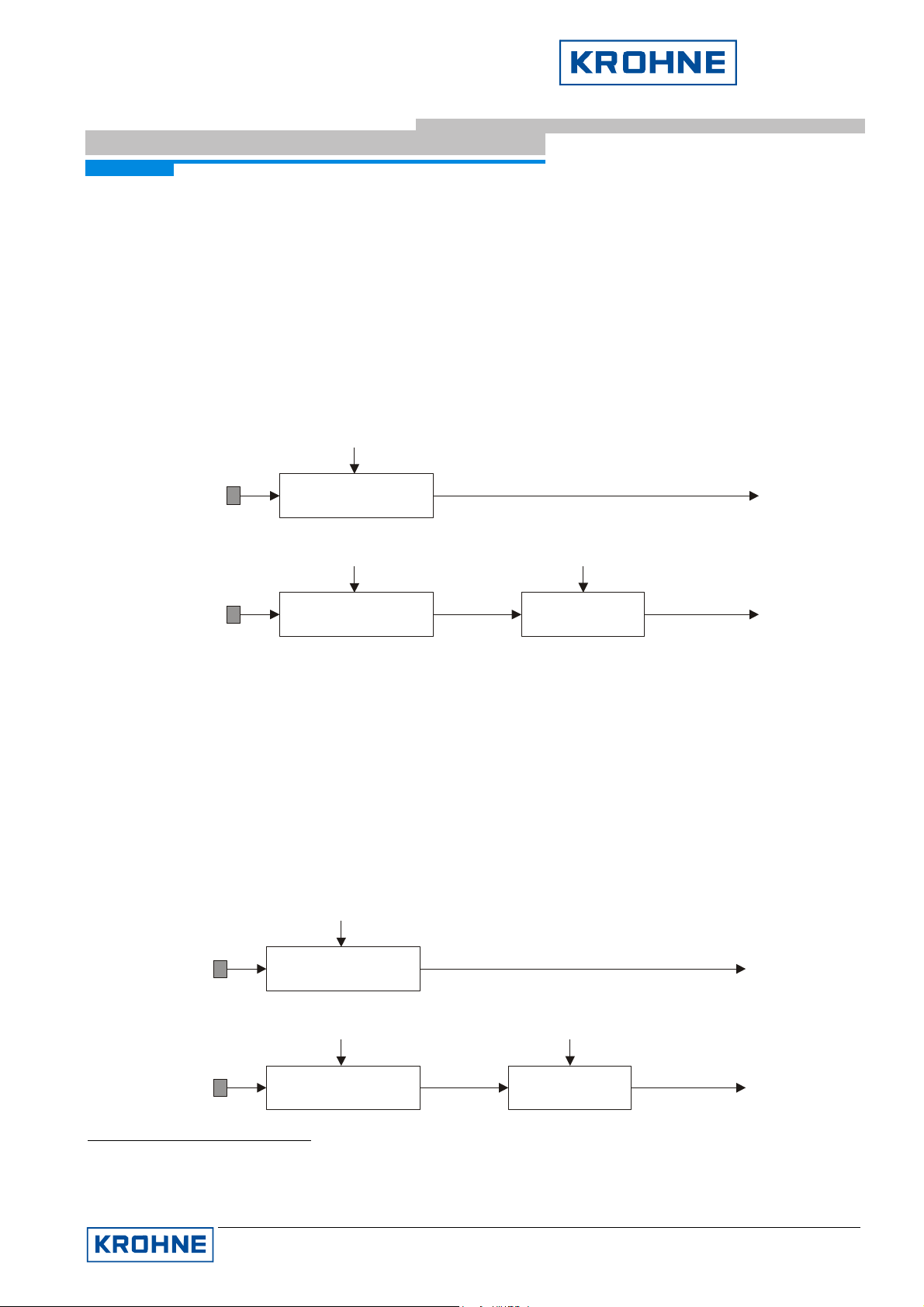
Supplementary Documentation Page 35 of 44
IFC090, IFC090 i with FF
IFC090 FF 01/2006
The input is a quantity unit per time unit (e.g. IN_1 is given as kg/h: quantity unit is kg, time unit is h). Since
the integration process operates with a time unit of seconds (s), the inputs IN_1 and IN_2 has to be adapted
to this unit. This has to be done by setting the parameters TIME_UNIT1 (for IN_1) and TIME_UNIT2 (for
IN_2) to the time unit used by the input (for the example above, TIME_UNIT1 has to be set to ‘hours‘ (h)).
Since the integration process adds the inputs IN_1 and IN_2 (if both are used), it is necessary to convert one
input into the unit of the other input. This is done by specifying a conversion factor to convert the quantity unit
of IN_2 to the quantity unit of IN_15. This conversion factor can be specified by setting the parameter
UNIT_CONV to the appropriate value.
Example:
IFC090-FF Configuration
IN_1
239.5 kg/min
TIME_UNIT1
(239.5 kg/min) / (60 s/min)
TIME_UNIT2
= min
= h
UNIT_CONV =
10
3.991 kg/s
-3
IN_2
9144.0 g/h
(9144.0 g/h) / (3600 s/h)
2.54 g/s
(2.54 g/s) * (10 kg/g)
-3
2.54 * 10 kg/s
-3
Accumulation input
The inputs of IN_1 and IN_2 are numbers of pulses. Since the integration process operates with a quantity
unit, it has to be specified for each input how many quantities of these unit represent one pulse. This has to
be done by setting the parameters PULSE_VAL1 (for IN_1) and PULSE_VAL2 (for IN_2) to the amount of
quantity per pulse.
Since the integration process adds the inputs IN_1 and IN_2 (if both are used), it is necessary to convert one
input into the unit of the other input. As at Rate input, this is done by specifying the conversion factor
UNIT_CONV, that defines a unit conversion from IN_2 into IN_1.
IN_1
236 pulses
PULSE_VAL1
236 pulses * 0.1 kg/pulse
PULSE_VAL2
= 0.1 kg/pulse
= 400g/pulse
UNIT_CONV =
10
23.6 kg
-3
IN_2
51 pulses
5
Since both inputs already have the same time base (if TIME_UNIT1 and TIME_UNIT2 are correct configured),
51 pulses * 400g/pulse
20400 g
20400 g * (10 kg/g)
-3
20.4 kg
it isn’t necessary to covert the time base, too.
KROHNE Messtechnik GmbH & Co. KG · Ludwig-Krohne-Str. 5 D-47058 Duisburg
Tel.: 0203-301 309 Fax: 0203-301389 · E-mail: krohne@krohne.de
Page 36

Supplementary Documentation Page 36 of 44
IFC090, IFC090 i with FF
IFC090 FF 01/2006
Example:
5.4.4 Setting the Flow Direction
The IFC090-FF integrators are capable of integrating three different kinds of flows:
• Forward (positive) Flow
• Reverse (negative) Flow
• Net Flow (positive- and negative flow)
By default, Integrator 1 is configured to integrate over Forward Flow and Integrator 2 over Reverse Flow.
This configuration can be changed by modifying the parameter INTEG_OPTS in the following way:
• Flow Forward (default for Integrator 1)
Enable option ‘Flow forward’ in parameter INTEG_OPTS (i.e. set to true), and ensure that option ‘Flow
reverse’ is disabled (i.e. set to false).
• Flow Reverse (default for Integrator 2)
IFC090-FF Configuration
Enable option ‘Flow reverse’ in parameter INTEG_OPTS (i.e. set to true), and ensure that option ‘Flow
forward’ is set disabled (i.e. set to false).
• Net Flow
Ensure that both options ‘Flow forward’ and ‘Flow reverse’ are disabled (set to false).
5.4.5 Type of Integration
The IFC090-FF integrators support the following seven Fieldbus Foundation specified integrator types, which
can be selected in parameter INTEG_TYPE:
Integrator Types Description
Up auto Totalization starts with 0.0 and counts up with automatic reset if the setpoint
TOTAL_SP is reached.
Up demand Totalization starts with 0.0 and counts up. A reset isn’t performed except either a
reset is initiated by a write to RESET_IN or OP_CMD_INT.
Down auto Totalization starts with the setpoint TOTAL_SP and counts down with automatic
reset if 0.0 is reached.
Down demand Totalization starts with the setpoint TOTAL_SP and counts down. A reset isn’t
performed except a rest is initiated by a write to RESET_IN or OP_CMD_INT.
Periodic Totalization starts with 0.0 and counts up. An automatic reset is performed in
accordance to the time given in parameter CLOCK_PER.
NOTE:
RESET_IN and OP_CMD_INT resets are disabled and would produce a ‘Wrong
Mode for Request Error’.
Demand Totalization starts with 0.0 and counts up. To perform a reset, the operator has to
write ‘reset’ to parameter OP_CMD_INT.
Periodic & Demand Same as ‘Periodic’ with the exception that RESET_IN and OP_CMD_INT resets
are possible.
KROHNE Messtechnik GmbH & Co. KG · Ludwig-Krohne-Str. 5 D-47058 Duisburg
Tel.: 0203-301 309 Fax: 0203-301389 · E-mail: krohne@krohne.de
Page 37

Supplementary Documentation Page 37 of 44
IFC090, IFC090 i with FF
IFC090 FF 01/2006
The a.m. setpoint TOTAL_SP can be set by user to an arbitrary value and is writable in every Integrator Block
operation mode. It defines the reset or starting points for the Up- and Down-integration types.
RESET_IN and OP_CMD_INT can be used to initiate an operator controlled reset. While RESET_IN is an input
parameter, which can be linked to any discrete output parameter of another block, OP_CMT_INT is a contained
parameter, which only can be changed by a direct write.
For the Periodic integration type, it is necessary to define a time, the totalization is being reset. CLOCK_PER is
the parameter referenced for this time and interpreted as value with unit seconds. The user can set this
parameter to any arbitrary value.
5.4.6 Integrator Reset Strategies
Depending on the chosen type of Integration (see 5.4.5), the integrators support different kinds of reseting the
totalization (i.e. the value of output parameter OUT). In the following, possible reset strategies are described
subject to the integration type:
Up auto
IFC090-FF Configuration
There are two kinds of reset possible:
• Automatic Reset
Reference point is the value of TOTAL_SP. If the totalization, i.e. the OUT value, exceeds TOTAL_SP, it is
reset to zero (0.0). A snapshot of the value at which the reset happened is saved in parameter STOTAL6.
• Operator Reset
No integrator internal reference point is used, but an input signal coming from another block or the operator.
By writing ‘reset’ to parameter OP_CMT_INT, the operator is able to reset the totalization at any point in
time.
If the operator wants to define a control strategy for resetting the totalization, it can use the input parameter
RESET_IN. Connecting this parameter with a different block’s discrete output parameter makes is possible
to reset the totalization by sending a value not equal to zero (0) via this connection.
Up demand
Only one kind of reset is possible: Operator Reset. See ‘Up auto‘ above for details.
Down auto
Similar two Up auto, two kinds of reset are possible:
• Automatic Reset
Reference point is 0.0. If the totalization, i.e. the OUT value, falls below 0.0, it is reset to TOTAL_SP. A
snapshot of the value at which the reset happened is saved in parameter STOTAL7.
• Operator Reset
See ‘Up auto’, ‘Operator Reset’ for details.
6
This could be useful, since normally the totalization isn’t reset exactly with the value of TOTAL_SP, but with a value with an additional
amount of measurement quantity.
7
This could be useful, since normally the totalization isn’t reset exactly with the value of TOTAL_SP, but with a value with an additional
amount of measurement quantity.
KROHNE Messtechnik GmbH & Co. KG · Ludwig-Krohne-Str. 5 D-47058 Duisburg
Tel.: 0203-301 309 Fax: 0203-301389 · E-mail: krohne@krohne.de
Page 38

Supplementary Documentation Page 38 of 44
IFC090, IFC090 i with FF
IFC090 FF 01/2006
Down demand
Only one kind of reset is possible: Operator Reset. See ‘Down auto‘ above for details.
Periodic
In difference to the integration types so far, this type does not support resets depending on totalization values
and/or operator signals. The periodic integration type also performs a automatic reset, but this reset is caused
by a elapsed time duration. If since the last reset the time specified in CLOCK_PER is elapsed, the totalization
is reset to zero (0.0).
An operator based reset is not possible; in contrast a write to OP_CMD_INT or RESET_IN would cause a
‘Wrong Mode for Request’ error.
Demand
Automatic resets are not performed with this setting, only operator controlled resets are possible. A write to
OP_CMD_INT or RESET_IN, respectively are the only possibilities to cause a totalization reset.
Periodic & Demand
IFC090-FF Configuration
This combines the reset possibilities of settings ‘Periodic’ and ‘Demand’, i.e. time based and operator resets are
possible.
Normally, the reset residual (i.e. the absolute difference between the reset point and the current value just
before the reset) isn’t considered in any way. But in some application it may be important, to carry this residual
to the next integration cycle. Enable option ‘Carry’ (i.e. set true) in parameter INTEG_OPTS. In order to
configure how to carry over the residual,
Common to all resets is the handling of the following parameters:
STOTAL
Snapshot of the totalization value just before the last reset.
SRTOTAL
Snapshot of the RTOTAL, i.e. input values with BAD status, just before the last reset.
SSP
Snapshot of the Set Point, i.e. setting of TOTAL_SP, just before the last reset. Useful, if TOTAL_SP was
changed since the last reset.
N_RESET
Number of resets. Useful to verify if a reset happened since the last reset.
RESET_CONFIRM
Used by control systems to confirm a reset, if confirmation is configured.
To configure reset confirmation, enable option ‘Confirm reset’ (i.e. set to true) in parameter INTEG_OPTS.
KROHNE Messtechnik GmbH & Co. KG · Ludwig-Krohne-Str. 5 D-47058 Duisburg
Tel.: 0203-301 309 Fax: 0203-301389 · E-mail: krohne@krohne.de
Page 39

Supplementary Documentation Page 39 of 44
IFC090, IFC090 i with FF
IFC090 FF 01/2006
If the control system should be notified about a reset events, this must be enabled by setting the option
‘Generate reset event’ in parameter INTEG_OPTS.
5.4.7 Trip and Pre-trip Handling
TOTAL_SP marks not only the value for automatic resets as described in the former section, it also serves as
trip value for batch totalizations.
Batch totalizations are possible for integration types (see 5.4.5) ‘Up auto’, ‘Up demand’, ‘Down auto’, and ‘Down
demand’ and works as follows:
UP auto and UP demand
If OUT ≥ PRE_TRIP ⇒ OUT_PTRIP is set (i.e. set to 255)
If OUT ≥ TOTAL_SP ⇒ OUT_TRIP is set (i.e. set to 1)
Down auto and Down demand
If OUT ≤ PRE_TRIP ⇒ OUT_PTRIP is set (i.e. set to 255)
IFC090-FF Configuration
If OUT ≤ 0 ⇒ OUT_TRIP is set (i.e. set to 1)
If a reset occurs, the conditions that set OUT_PTRIP and OUT_TRIP are no longer true, so they are cleared. In
any case, OUT_TRIP is set for at least 5 seconds, even if a reset happened. From this, the control system
should be able to read the set OUT_TRIP for at least one time.
5.4.8 Status Handling
The status of the output totalization value OUT depends on the statuses of all integrated input values of IN_1
and IN_2.
All inputs are grouped in inputs with Good status, and inputs with Bad status (whereas an input with Uncertain
status is deemed to be Bad). The dynamic parameter PCT_INCL always reflects the percentage ratio of inputs
with Bad status.
What status the output has depends on this Bad ratio. The resulting output status can be configured by setting
the parameters GOOD_LIM and UNCERT_LIM. The relations between these parameters, the ratio PCT_INCL,
and the resulting output status are as follows:
If 100% ≤ PCT_INCL < GOOD_LIM ⇒ Output status = Good
If GOOD_LIM ≤ PCT_INCL < UNCERT_LIM ⇒ Output status = Uncertain
If UNCERT_LIM ≤ PCT_INCL ≤ 0 ⇒ Output status = Bad
5.4.9 Input Value Handling
Normally, the inputs of IN_1 and IN_2 are used as they are:
KROHNE Messtechnik GmbH & Co. KG · Ludwig-Krohne-Str. 5 D-47058 Duisburg
Tel.: 0203-301 309 Fax: 0203-301389 · E-mail: krohne@krohne.de
Page 40

Supplementary Documentation Page 40 of 44
IFC090, IFC090 i with FF
IFC090 FF 01/2006
• input status = Good ⇒ value is used for the integration.
• input status = Uncertain ⇒ value of last input with Good status is used instead
• input status = Bad ⇒ value of last input with Good status is used instead
This strategy can be enabling by one or more of the following INTEG_OPTS options:
IFC090-FF Configuration
KROHNE Messtechnik GmbH & Co. KG · Ludwig-Krohne-Str. 5 D-47058 Duisburg
Tel.: 0203-301 309 Fax: 0203-301389 · E-mail: krohne@krohne.de
Page 41

Supplementary Documentation Page 41 of 44
IFC090, IFC090 i with FF
IFC090 FF 01/2006
INTEG_OPTS Description if enabled (i.e set to true)
IFC090-FF Configuration
Use Uncertain
Input values of IN_1 or IN_2 are also used for the integration, if their status are
Uncertain. The calculation of RTOTAL isn’t affected by this setting (i.e. the value
is used for the integration, but even though the input is interpreted as Bad and
added to RTOTAL).
Use Bad
Status of input values of IN_1 or IN_2 isn’t interpreted as Bad value in the
calculation of RTOTAL even if they’re really Bad.
NOTE:
This doesn’t mean, that the values of inputs with Bad status are used for the
integration! The last value with Good status is used further on!
Add zero if Bad
Instead of using the last value with Good status for integration, zero (0.0) is used,
if the status of the input of IN_1 or IN_2 is Bad.
KROHNE Messtechnik GmbH & Co. KG · Ludwig-Krohne-Str. 5 D-47058 Duisburg
Tel.: 0203-301 309 Fax: 0203-301389 · E-mail: krohne@krohne.de
Page 42

Supplementary Documentation Page 42 of 44
IFC090, IFC090 i with FF
IFC090 FF 01/2006
6 Troubleshooting
This chapter documents the possible errors that can occur. They are ordered by error parameter or block.
Normally, the errors don’t occur solely, but in conjunction with other errors, described here.
6.1 BLOCK_ERROR
Each block has a parameter BLOCK_ERR, that reflects possible problems with the block. The following
describes these possible problems and the necessary action to be taken by the user.
6.1.1 Resource Block
The following table lists the block errors documented by the Resource Block:
Error Code Description Action
Troubleshooting
Out of Service
Power-up
Device needs
Maintenance
Memory Failure
Input Failure
Other
Target mode is set to ‘Out of
Service (OOS)’
Power failure of measurement
electronics (NOTE: Not the
bus power!)
Fatal error of the
measurement electronics
Device memory failure Replace signal converter or contact KROHNE service.
AD converter error. Replace signal converter or contact KROHNE service.
Other hardware problem. Replace signal converter or contact KROHNE service.
If Automatic is the desires target mode, set
MODE_BLK target to ‘Automatic (Auto)’
This requires an action at the device’s display:
Quit the ‘ERROR QUIT’ menu at the device’s display.
Refer to the ‘Installation and operating instructions,
Signal converters for electromagnetic flowmeters’
manual.
Note: No counting during power failure.
Replace signal converter or contact KROHNE service.
6.1.2 Transducer Block
The following table lists the block errors documented by the Transducer Block:
Error Code Description Action
Out of Service
Target mode is set to ‘Out of
Service (OOS)’
Communication problem
between FF module and
If Automatic is the desired target mode, set
MODE_BLK target to ‘Automatic (Auto)’
Replace signal converter or contact
KROHNE service.
measurement module
Device Needs Maintenance Now
AD converter error. Replace signal converter or contact
KROHNE service.
KROHNE Messtechnik GmbH & Co. KG · Ludwig-Krohne-Str. 5 D-47058 Duisburg
Tel.: 0203-301 309 Fax: 0203-301389 · E-mail: krohne@krohne.de
Page 43
Supplementary Documentation Page 43 of 44
IFC090, IFC090 i with FF
IFC090 FF 01/2006
6.1.3 Analog Input Block
The follwowing table lists the block errors documented by the Analog Input Block:
Error Code Description Action
Troubleshooting
Out of Service
Target mode is set to
‘Out of Service (OOS)’
‘Block Configuration
If Automatic is the desired target mode, set MODE_BLK target to
‘Automatic (Auto)’.
See ‘Block Configuration Error’ description below.
Error’ is also set
Block
Configuration
Value of CHANNEL ≠
1
Set the value of CHANNEL to 1.
Error
Value of L_TYPE is
unspecified.
Set value of L_TYPE to ‘Direct’, ‘Indirect’, or ‘Indirect Square
Root’.
NOTE:
If set to ‘Indirect’ or ‘Indirect Square Root’, don’t forget to
configure parameter OUT_SCALE!
Unit of XD_SCALE is
not equal to unit of
Transducer Block
parameter
PRIMARY_VALUE_R
Set the unit of XD_SCALE to the same unit as
PRIMARY_VALUE_RANGE.
NOTE:
Since the unit of PRIMARY_VALUE_RANGE is fixed to m
this always must be m
3
/s.
3
/s,
ANGE
Some IFC090 measurement problems can be read from the Analog Input Block parameter OUT status. The
following table lists (almost) all of the Analog Input OUT statuses that are mapped to IFC090 (Precondition:
Analog Input Block is configured and target mode is set to Automatic, see 5.3):
OUT status Description Action
Good:NonSpecific:NotLi
mited
Bad:NonSpecific.NotLi
mited
No IFC090 problem
detected
Old measurement
value. The value has
n/a
Normally, this status will disappear after a short period. If not,
replace signal converter or contact KROHNE service.
not been updated for
a long period of
time.
Bad:ConfigurationError:
NotLimited
Analog Input Block
configuration is
Check parameters CHANNEL, L_TYPE and XD_SCALE.
Configure them as described in 5.3.
incorrect.
Bad:DeviceFailure:NotL
imited
Bad:DeviceFailure:Con
AD converter error. Replace signal converter or contact KROHNE service.
stant
Bad:SensorFailure:Con
stant
Measured value is
outside of sensor
Check instrument parameters and correct it if necessary. Error
messages deleted automatically.
range.
Bad:OutOfService:NotLi
mited
Uncertain:NonSpecific:
NotLimited
Actual mode is Out
of Service.
Pipe is empty Fill the pipe with media.
AD converter
overshooted.
Check the target mode and ensure that it is set to ‘Auto’ mode.
Check instrument parameters and correct it if necessary. Error
messages deleted automatically.
KROHNE Messtechnik GmbH & Co. KG · Ludwig-Krohne-Str. 5 D-47058 Duisburg
Tel.: 0203-301 309 Fax: 0203-301389 · E-mail: krohne@krohne.de
Page 44

Supplementary Documentation Page 44 of 44
t
IFC090, IFC090 i with FF
IFC090 FF 01/2006
Other possibly occuring statuses correspond to the PRIMARY_VALUE statuses. See 6.1.3 for details.
6.1.4 Integrator Blocks
The follwowing table lists the block errors documented by the Integrator Blocks:
Error Code Description Action
Troubleshooting
Out of Service Target mode is set
to ‘Out of Service
If Automatic is the desired target mode, set MODE_BLK target
to ‘Automatic (Auto)’
(OOS)’
Memory Failure Device memory
Replace signal converter or contact KROHNE service.
failure.
6.2 Transducer Block XD_ERROR
The Transducer Block has a special error parameter XD_ERROR. If this error displays the error ‘Electronics
failure’, the AD converter of the sensor seems to have problems. Please contact the KROHNE support team, if
this error remains.
6.3 Measurement Value Status
Besides the problems that are displayed in the BLOCK_ERR parameter of each block, the status of the
Transducer Block parameter PRIMARY_VALUE (the raw measurement value obtained from the device) can
provide further information on possible reasons for measurement problems.
The following table lists possible indications:
PRIMARY_VALUE
state
BAD:OutOfService:Not
Limited
BAD:DeviceFailure:Not
Limited
BAD:SensorFailure:Low
Limited
BAD:SensorFailure:Hig
hLimited
Uncertain:NonSpecific:
NotLimited
Uncertain:NonSpecific:
Constant
Uncertain:SensorConve
rsionNotAccurate:NotLi
mited
Description Action
Target mode is set
to ‘Out of Service
If Automatic is the desired target mode, set MODE_BLK targe
to ‘Automatic (Auto)’
(OOS)’
AD converter fatal
Contact the KROHNE support team.
error.
Measured value is
below the sensor
Check instrument parameters and correct it if necessary. Error
messages deleted automatically.
range.
Measured value is
above the sensor
Check instrument parameters and correct it if necessary. Error
messages deleted automatically.
range.
Pipe is empty. Fill the pipe with media.
AD converter
warning.
Current mode is
‘Manual (Man)’
AD converter
overshooted.
Check instrument parameters and correct it if necessary. Error
messages deleted automatically.
If Automatic is the desired mode, set MODE_BLK traget to
‘Automatic (Auto)’.
Check instrument parameters and correct it if necessary. Error
messages deleted automatically.
KROHNE Messtechnik GmbH & Co. KG · Ludwig-Krohne-Str. 5 D-47058 Duisburg
Tel.: 0203-301 309 Fax: 0203-301389 · E-mail: krohne@krohne.de
 Loading...