

Page 1
www.krohne.com
7022812100
C
KROHNE 03/2005
GM
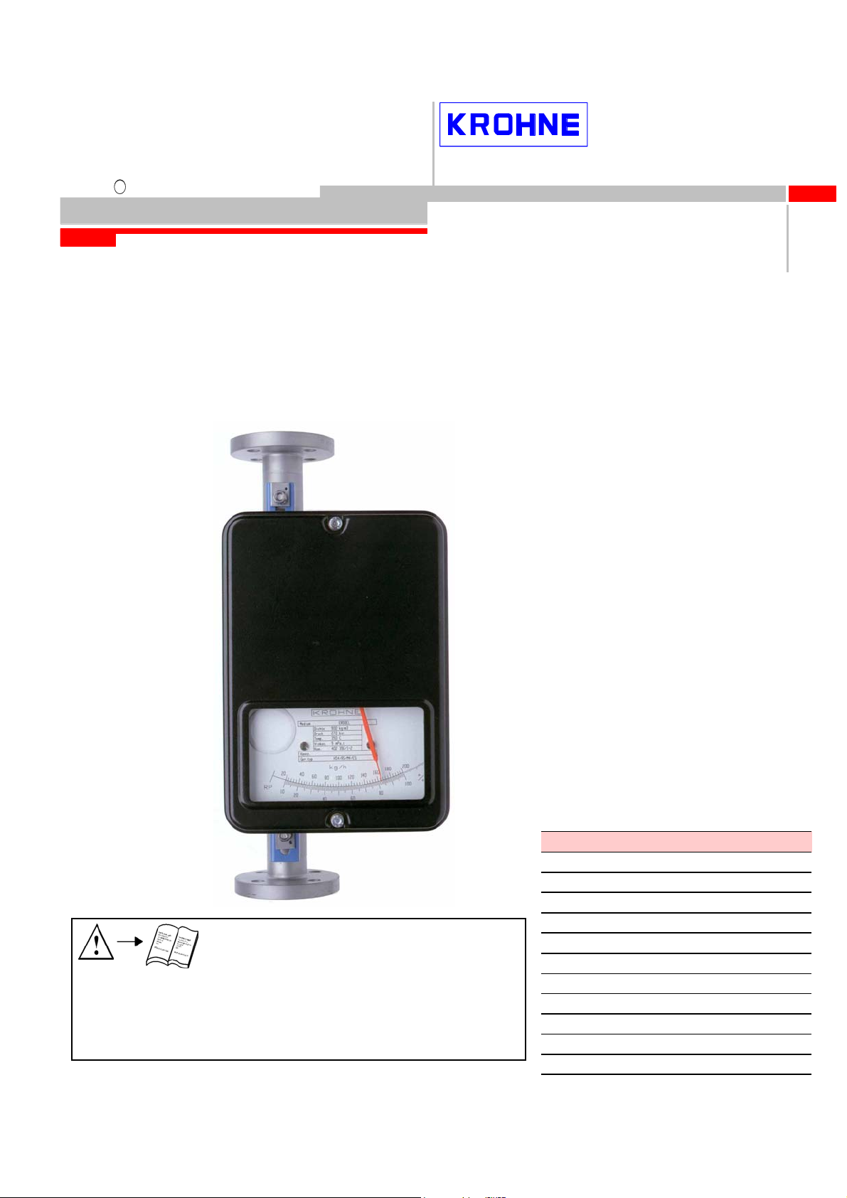
Operating Instructions
Installation and
H54 / M4
Variable Area Flowmeter
Vortex flowmeters
Flow controllers
Electromagnetic flowmeters
Ultrasonic flowmeters
Mass flowmeters
Level measuring instruments
For explosion protected devices please refer to Supplementary
Communications technology
Installation an Operating Instructions:
Engineering systems & solutions
GA24/... Cat. II2GD
Switches, counters, displays and recorders
Cat. II3GD without electr. built-in parts Id. No. 702271##00
Heat metering
Pressure and temperature
Variable area flowmeters
Page 2

Product liability and warranty
The variable area flowmeter is suitable for measuring the volume flow of liquids, gases and vapor.
Special regulations apply for use in explosion-hazardous areas. Responsibility for the suitability and
usage to the intended purpose of these flowmeters rests solely with the operator.
Improper installation or improper operation of the flowmeters may lead to the loss of warranty. In addition,
the "General conditions of sale" which forms the basis of the purchase contract are applicable.
The calculation of the pressurized parts is effected with allowance for corrosion, erosion through abrasion
or cavitation.
If the flowmeter needs to be returned to KROHNE Messtechnik, please note the information at the end of
these installation and operating instructions.
Scope of delivery
The scope of delivery of the variable area flowmeter in the version respectively ordered includes:
- Installation and operating instructions Ident. No. 702281##00
For explosion protected devices please refer to Supplem. Installation an Operating Instructions:
H54/... Cat. II2GD Cat. II3GD without electr. built-in parts Id. No. 702271##00
- Supply without installation accessories (screw bolts, flange seal and cabling)
Special certificates (supplied to order only)
- Record on setting in works
- Test certificate to EN 10204:
- Pressure test, paint penetration test, irradiation test, leak test,
ultrasonic test, helium leakage test,
- Cleaning to works regulations.
2 H54 Installation and operating instructions
Page 3

Table of Contents
Product liability and warranty ................................................................................................................... 2
1 General................................................................................................................................................ 4
1.1 Type code ........................................................................................................................................ 4
1.2 Marking ............................................................................................................................................ 4
1.3 Key for Pressure Equipment Directive ............................................................................................5
1.4 Functional principle.......................................................................................................................... 5
2 Installation and Start-up.................................................................................................................... 6
2.1 Protection during shipment.............................................................................................................. 6
2.2 Prerequisite for the installation ........................................................................................................ 6
2.3 Preparation of the pipeline............................................................................................................... 6
2.4 Installation in the pipeline ................................................................................................................ 6
2.5 Fastening torque.............................................................................................................................. 6
2.6 Magnetic filters ................................................................................................................................ 7
2.7 Observance of the IP degree (NEMA Type) of protection............................................................... 7
2.8 Start-up............................................................................................................................................ 7
2.9 Measurement of liquids ................................................................................................................... 7
2.10 Measurement of gases.................................................................................................................... 7
3 Flow tables ......................................................................................................................................... 8
4 Materials ............................................................................................................................................. 9
5 Technical Data.................................................................................................................................. 10
6 Medium Temperatures..................................................................................................................... 10
7 Dimensions and weights................................................................................................................. 11
8 Limit switches .................................................................................................................................. 12
8.1 Electrical connection...................................................................................................................... 12
8.2 Setting............................................................................................................................................ 12
8.3 Technical data of limit switches ..................................................................................................... 12
9 Electrical signal output ESK II........................................................................................................ 13
10 Electrical signal output ESK3-PA................................................................................................... 14
11 Maintenance ..................................................................................................................................... 15
Information on returning instruments.................................................................................................... 15
Form for returning the instrument.......................................................................................................... 16
3 H54 Installation and operating instructions
Page 4

1 General
1.1 Type code
The type code consists of the following elements: 1)
H 5 4 / / / /
1 2 3 4 5 6
1 Series measuring unit H54
2 Materials
RR : stainless Steel
C : stainless steel with PTFE liner
3 Heating jacket design
B : with heating jacket
4 Display part series
M4 : mechanical indicator
M10 : electronic transmitter with LC display M10
5 Signal output (M4 display)
ESK : electronic transmitter
6 Limit switch
K1 : one limit switch
K2 : two limit switches
1) Positions which are not used in the type code are not required.
1.2 Marking
The type marking of the complete instrument is carried out at the display part by means of the rating plates
shown here (also refer to the type code).
Example:
MD: Manufacturing date
PS: Max. permissible operating
pressure at max. permissible operating temperature TS
PT max: Maximum pressure tested
TS: Max. operating temperature
PED: Directive for Pressure Equipment
Tag No : Measuring point tag
0044: Identification number of the supervising office for
EC Directive for Pressure Equipment 97/23/EC
SN: Serial number
SO: Sales order / item
KO: KROHNE order
V251…: Product configurator code
AC: Article code
4 H54 Installation and operating instructions
Page 5
1.3 Key for Pressure Equipment Directive
PED / / /
1 2 3 4 5
1 Pressure Equipment Directive
2 Fluid
G Gases, liquefied gases, gases dissolved under pressure, vapors and those liquids
whose vapor pressure lies more than 0.5 bars over the normal atmospheric pressure
(1013 mbars) at the maximum permissible temperature
L Liquids whose vapor pressure lies a maximum of 0.5 bars above the atmospheric
pressure at the maximum permissible temperature
3 Fluid group
1 Group 1: Explosion-hazardous, highly flammable, readily flammable, flammable
(when the maximum permissible temperature lies above the flash point),
highly toxic, toxic, fire stimulating
2 Group 2: All the fluids not specified in Group 1
4 Category
3.3 In accordance with Article 3.3 of Directive 97/23/EC
I Category I to 97/23/EC
II Category II to 97/23/EC
III Category III to 97/23/EC
5 Conformity evaluation process
SEP Solid engineering practice
A Module A internal process inspection
A1 Module A1 internal process inspection with supervision of the acceptance
H Module H Comprehensive quality assurance
The PED key marking is contained on the rating plate of the instrument.
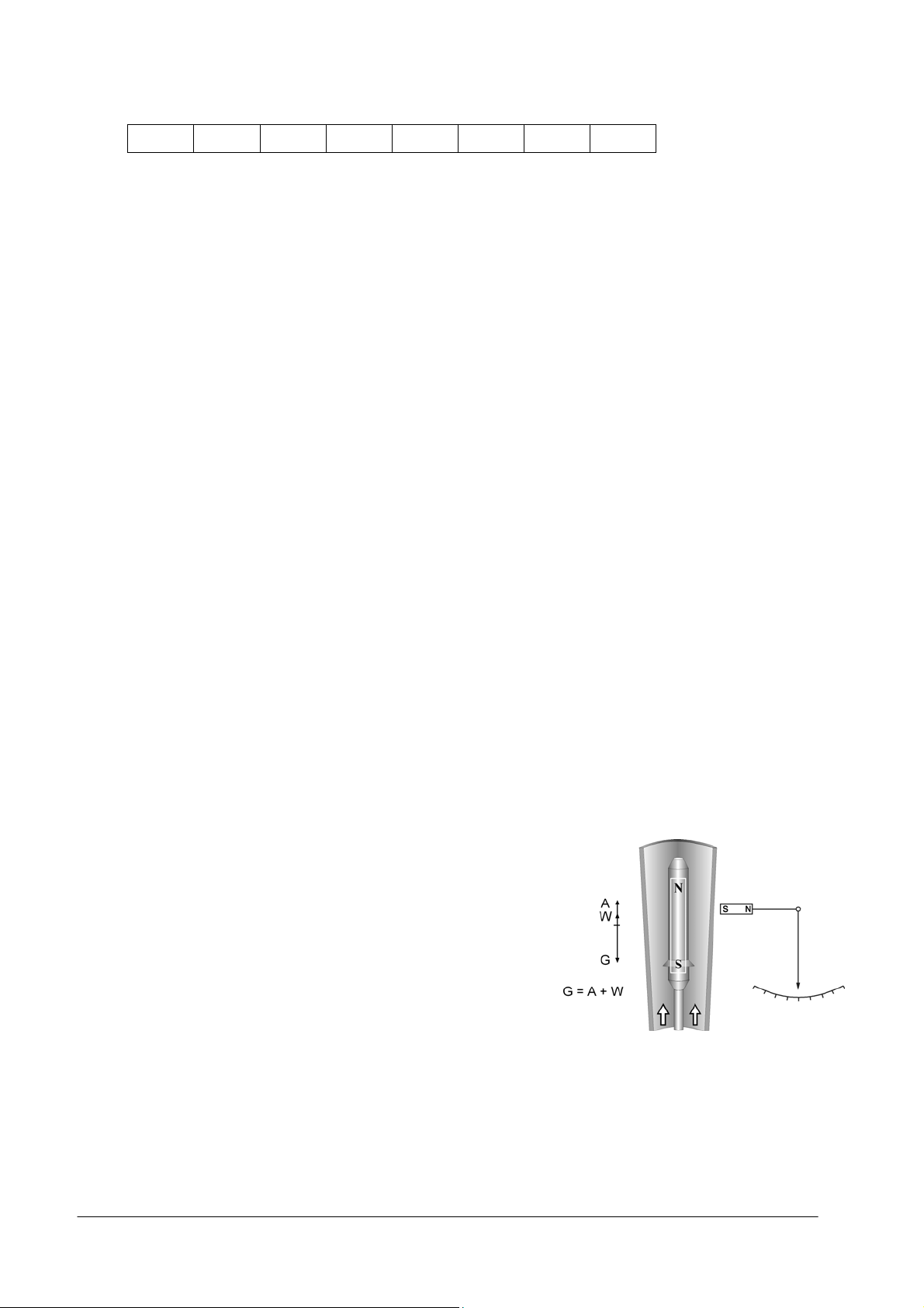
1.4 Functional principle
The flowmeter operates in accordance with the float measuring
principle.
A metal cone is installed in the measuring unit H54, in which
a suitably formed float can move freely up and down.
The flowmeter is inserted into a vertical pipeline and the
medium flows through it from bottom to top.
The guided float adjusts itself so that the buoyancy force
A acting on it, the wave resistance W and its weight G are
in equilibrium (G = A + W).
An annular gap which depends on the flow rate results.
The height of the float in the measuring unit, which depends
on the flow, is transmitted by a magnetic coupling and
displayed on a scale. Strong magnetic fields can lead to
deviations in the measured value.
The installation of several instruments in immediate vicinity to
each other does not cause notable influences.
5 H54 Installation and operating instructions
Page 6

2 Installation and Start-up
2.1 Protection during shipment
The sensing arm and cam plate are secured by a rubber band.
2.2 Prerequisite for the installation
The operating pressure of the plant may not exceed the value indicated on the rating plate.
Ensure that the parts coming into contact with the medium are compatible with the material. (For the list
of the materials please refer to the chapter on the materials of the instrument designs.)
The ambient and medium temperatures may not exceed certain maximum values.
The variable area flowmeter has to be installed vertically (float measuring principle - flow direction from
bottom to top).
In order to prevent distortions the connecting flanges have to face each other axially and in parallel.
2.3 Preparation of the pipeline
The pipeline is to be supported by suitable installation measures, so that vibrations at the pipeline are
prevented and axial stresses on the instrument are minimized.
A straight unimpeded inflow section of ≥ 5 x DN before the instrument and a straight
outflow section of ≥ 3 x DN behind the instrument are recommended.
Shutoff and control devices are to be positioned in the flow direction behind the measuring unit.
For installation recommendations please also refer to the Directive VDE/VDI 3513, Sheet 3.
2.4 Installation in the pipeline
The instrument may not be subjected to tensile or compressive stresses through the pipelines.
Immediately before carrying out the installation check whether the instrument is free of foreign particles.
Screws, bolts and seals (provided by customer) are to be selected in accordance with the pressure stage
of the connecting flange or the operating pressure.
The inside diameter of the flange deviates from the standard dimensions.
Flange seal standard DIN 2690 (ASME B16.21) can be applied without any limitation.
Align the seals. Tighten the nuts with the tightening torques of the corresponding pressure stage.
2.5 Fastening torque
The flange bolts are to be tightened with the following maximum torques in case of measuring units with
PTFE liner or of measuring units with ceramic lining and PTFE sealing surface:
Nominal size to
DIN 2501 ASME B 16.5 DIN ASME DIN ASME 150 lbs
DN PN Inch lbs 150 lbs 300 lbs Nm ft·lbf Nm ft·lbf
15 40 ½” 150/300 4 x M 12 4 x ½” 4 x ½” 9.8 7.1 5.2 3.8
25 40 1” 150/300 4 x M 12 4 x ½” 4 x 5/8” 21 15 10 7.2
50 40 2” 150/300 4 x M 16 4 x 5/8” 8 x 5/8” 57 41 41 30
80 16 3” 150/300 8 x M 16 4 x 5/8” 8 x ¾” 47 34 70 51
100 16 4” 150/300 8 x M 16 8 x 5/8” 8 x ¾” 67 36 50 36
Bolts Max. tightening torque
125 16 5" 150/300 8 x M 16 8 x 5/8“ 8 x ¾“ 67 48 75 54
150 16 6" 150/300 8 x M 20 8 x ¾“ 8 x ¾“ 88 64 94 68
6 H54 Installation and operating instructions
Page 7

2.6 Magnetic filters
Magnetic filters are used when the medium contains particles which can be influenced magnetically. The
magnetic filter is to be installed in the flow direction before the flowmeter. Magnetic bars are positioned
helically in the filter so that an optimal efficiency at a low pressure loss is achieved. All the magnets are
coated individually with PTFE to protect against corrosion. Two models are available:
Type F Type FS
Fitting part with flange Fitting part without flange
Overall length 100 mm Overall length 50 mm
Materials 1.4571 (316 Ti)
2.7 Observance of the IP degree (NEMA Type) of protection
The following instructions are to be observed in order to observe the IP degree (Nema Type) of electrical
built-in parts.
- After the connecting cable has been introduced, tighten the outlet nut.
- All the cable glands which are not used remain closed with blanking plugs.
- Do not kink lines directly at the cable gland.
- Provide a drain bend
- The feed lines may not be subjected to mechanical strains. Refer to the description
of the electrical supplementary components for this device.
Cable glands / screwed glands: PG11 - line diameter 8 to 10mm
2.8 Start-up
A minimum operating pressure (pre-pressure) is required to operate the instrument.
Medium Pressure loss : Operating pressure
Liquids 1 : 2
Gases (without damping) 1 : 5
Gases (with damping) 1 : 2
For the pressure losses please refer to the flow tables
2.9 Measurement of liquids
Vent the pipeline during starting-up in order to avoid liquid beats.
Open valves slowly!
2.10 Measurement of gases
Pulsations of the medium are to be kept away from the instrument.
In case of gases increase the operating pressure slowly.
The flow is to be varied by means of adjusting valves, so that the float is not subjected to blows
(e.g. through solenoid valves) thus ensuring that damage to the measuring unit cannot occur.
Instruments for measuring the flow rate of gases can be equipped with a gas damping, in order to avoid
possible compression vibrations of the float.
If vibrations nevertheless occur at the float, these can be eliminated by installing a throttle valve or a
suitable aperture hole (on request) behind the instrument.
A float damping is recommended for gas measurement.
7 H54 Installation and operating instructions
Page 8

3 Flow tables
General
Reference conditions: Water at 20°C
Air at 20°C, 1.013 bar abs.
The conversion to other media or operating data (pressure, temperature, density, viscosity) is carried out
by means of the KROHNE calculation procedure KroVaCal on the basis of the VDE /VDI Guideline 3513.
The specified flow values amount to 100% values of the measuring range.
The turn-down range amounts to 10 : 1
The specified pressure losses apply for water and air at the maximum flow rate.
3.1 Flow table H 54 / DN15
Float material CrNi steel
Float form Water: N
Air: NA
Nominal size Water Air Max. pressure loss
DN ASME
mm inches No. No. l/h US GPM m3/h SCFM mbar psig
15 1½“
Cone Float
N NA N / NA
R10.03 10 16 0.07 0.4 0.28 60 0.87
R10.04 11 25 0.11 0.9 0.56 60 0.87
R10.06 11 40 0.18 1.2 0.74 60 0.87
R10.08 11 63 0.28 1.8 1.11 60 0.87
R11.07 31 100 0.44 2.8 1.74 65 0.94
R11.10 32 160 0.70 5 3.10 65 0.94
R11.17 33 250 1.10 8.5 5.27 70 1.02
R11.27 34 400 1.76 11.5 7.13 80 1.16
R12.21 42 630 2.77 20 12.4 100 1.45
R12.32 43 1000 4.40 26 16.1 140 2.03
8 H54 Installation and operating instructions
Page 9

3.2 Flow table H54 DN25 … DN150
Float material CrNi steel
Float form Water: CIVB, CIVTF
Air: CIVT, DIVBLD
Nominal
Cone
Float
size
DN ASME
mm inches No. No.
25 1" K20.12 21
K20.16
K20.23
K20.33
K20.49
K20.55
40 1 1/2" K40.37 41
K40.50
K40.54
50 2" K50.34 51
K50.57
K50.60
80 3" K80.23 81
K80.37
K80.40
K80.50
100 4" K102.35
K102.41
125 5" K122.39
K122.42
150 6" K152.45
CIV 102 50.000 220 120 1.74
CIV 102 63.000 277
TR 122 80.000 352 130 1.89
TR 122 90.000 396
TR 152 150.000 660 150 2.18
Water Air Max. pressure loss
C IV B C IV TF C IV T D IV BLD C IV B C IV TF C IV T C IV BLD
l/h US
800 3.52 500 2.20 12 7.44 20 12.4 46 0.67 19 0.28 13 0.19 21 0.30
1.000 4.40 600 2.64 15 9.31 25 15.5 48 0.70 19 0.28 14 0.20 24 0.35
1.600 7.04 1000 4.40 24 14.9 40 24.8 50 0.73 21 0.30 16 0.23 30 0.44
2.500 11.0 1600 7.04 35 21.7 60 37.2 60 0.87 26 0.38 19 0.28 38 0.55
4.000 17.6 2500 11.0 55 34.1 100 62.0 90 1.31 36 0.52 25 0.36 60 0.87
5.000 22.0 3000 13.2 70 43.4 130 80.6 110 1.60 48 0.70 32 0.46 80 1.16
6.300 27.7 4000 17.6 85 52.7 200 124 60 0.87 31 0.45 19 0.28 75 1.09
10.000 44.0 6000 26.4 125 77.5 280 174 90 1.31 41 0.59 25 0.36 100 1.45
12.500 55.0 7500 33.0 150 93.1 350 217 110 1.60 51 0.74 30 0.44 110 1.60
12.500 55.0 7000 30.8 160 99.3 450 279 65 0.94 30 0.44 11 0.16 90 1.31
16.000 70.5 9000 39.6 180 111 650 403 75 1.09 32 0.46 11 0.16 120 1.74
20.000 88.1 12000 52.8 200 124 750 465 100 1.45 44 0.64 12 0.17 140 2.03
20.000 88.1 12000 52.8 250 155 520 323 60 0.87 25 0.36 14 0.20 50 0.73
25.000 110 14000 61.6 300 186 620 385 70 1.02 26 0.38 14 0.20 52 0.75
30.000 132 16000 70.5 350 217 700 434 80 1.16 27 0.39 14 0.20 54 0.78
40.000 176 20000 88.1 400 248 900 558 90 1.31 29 0.42 15 0.22 56 0.81
l/h US
GPM
m3/h SCFM m3/h SCFM mbarpsig mbarpsig mbarpsig mbarpsig
GPM
135 1.96
140 2.03
4 Materials
Materials
Design
H 54
H 54 / RR CrNi-steel
H 54 / R PTFE * CrNi-steel
H 54 / Hastelloy Hastelloy B3 or C4 CrNi-Stahl HC
* With this liner, flanges are those of the next meter size up,
e.g. cone 20.12 with flange DN40 instead of DN 25
** Alternatively: cone of glass, gasket of PTFE (Only for cone DN 15)
9 H54 Installation and operating instructions
Measuring tube
1.4571
(316Ti)
1.4571
(316Ti)
with PTFE liner
Flange Cone Internals, seal
CrNi-steel
1.4571
(316Ti)
CrNi-steel
CrNi-steel
1.4571 (316Ti)
PTFE ** PTFE PTFE
1.4571 (316Ti)
Hastelloy B3 or
cladded
1.4571
(316Ti)
C4
strip
CrNi-steel
1.4571 (316Ti)
Hastelloy B3
or C4
Float
CrNi-steel
1.4571 (316Ti)
Hastelloy B3
or C4
Page 10

5 Technical Data
Accuracy class
to VDI/VDE Directive 3513, Sheet 2
Connections H 54
Flange dimensions to DIN EN 1092-1
Flange dimensions to ASME B 16.5
Pipe connection for Ermeto
Pipe connection for air cooling
Overall height
With flange connection (without seals)
Operating pressure PS
Directive 97/23/ EC of the Council of April 29, 1999 on mobile pressurized equipment (Directive for
Pressure Equipment) is applied. The maximum permissible operating pressure PS is calculated for the
maximum operating temperature TS. Both limits (PS and TS) are listed on the rating plate. As a rule PS
corresponds to the nominal pressure of the connection.
Pressure Tested PT
The pressure tested is calculated in accordance with the Directive for Pressure Equipment (97/23/EC) or AD
2000-HP30 under consideration of the maximum permissible operating pressure as well as the maximum
operating temperature.
Degree of protection
in accordance with EN 60529 / IEC 60529
1.0
DN 15 … DN 80 / PN 40
DN 80 … DN 150 / PN 16
½" … 6" class 150 lbs / RF or 300 lbs / RF
Ermeto 12
Ermeto 6, 8, 10 or 12
other on request
500 mm
IP 67, NEMA Type 4X / 6
6 Medium Temperatures
Max. Medium Temperatures TS without electrical built-in components -80 °C to +400 °C
Max. Medium Temperatures with ESK, K, KD
H 54 / M4 / ESK
H 54 / M4 / K ( KD )
Ambient temperature T
Ambient temperature T
amb.
with ESK, K, KD
amb.
Other temperatures on request
160 °C (DN 15 : 80 °C)
180 °C (DN 15 : 100 °C)
-40°C to + 90°C
-25 °C to +60 °C
10 H54 Installation and operating instructions
Page 11

7 Dimensions and weights
226
c 45 do
a
321
500 (DN 150 : 600)
b du
Nominal size Dimensions [mm]
DIN ASME
a b c du do
approx.
weight *
DN PN inches mm kg
15 40
25 40
40 40
50 40
80 40
½“
1“
1½“
2
3
23 410 97 125 23 23 5
34.5 380 109 165 34.5 34.5 7
50 380 120 175 45 50 9
67 380 128 185 57 67 12
89 380 147 190 89 89 25
80 16 3 89 380 147 190 89 89 27
100 16 4 106 380 164 205 93 106 29
125 16 5 148 380 175 225 115 148 35
150 16 6 175 380 190 240 127 175 42
* Weights with DIN-Flanges
11 H54 Installation and operating instructions
Page 12
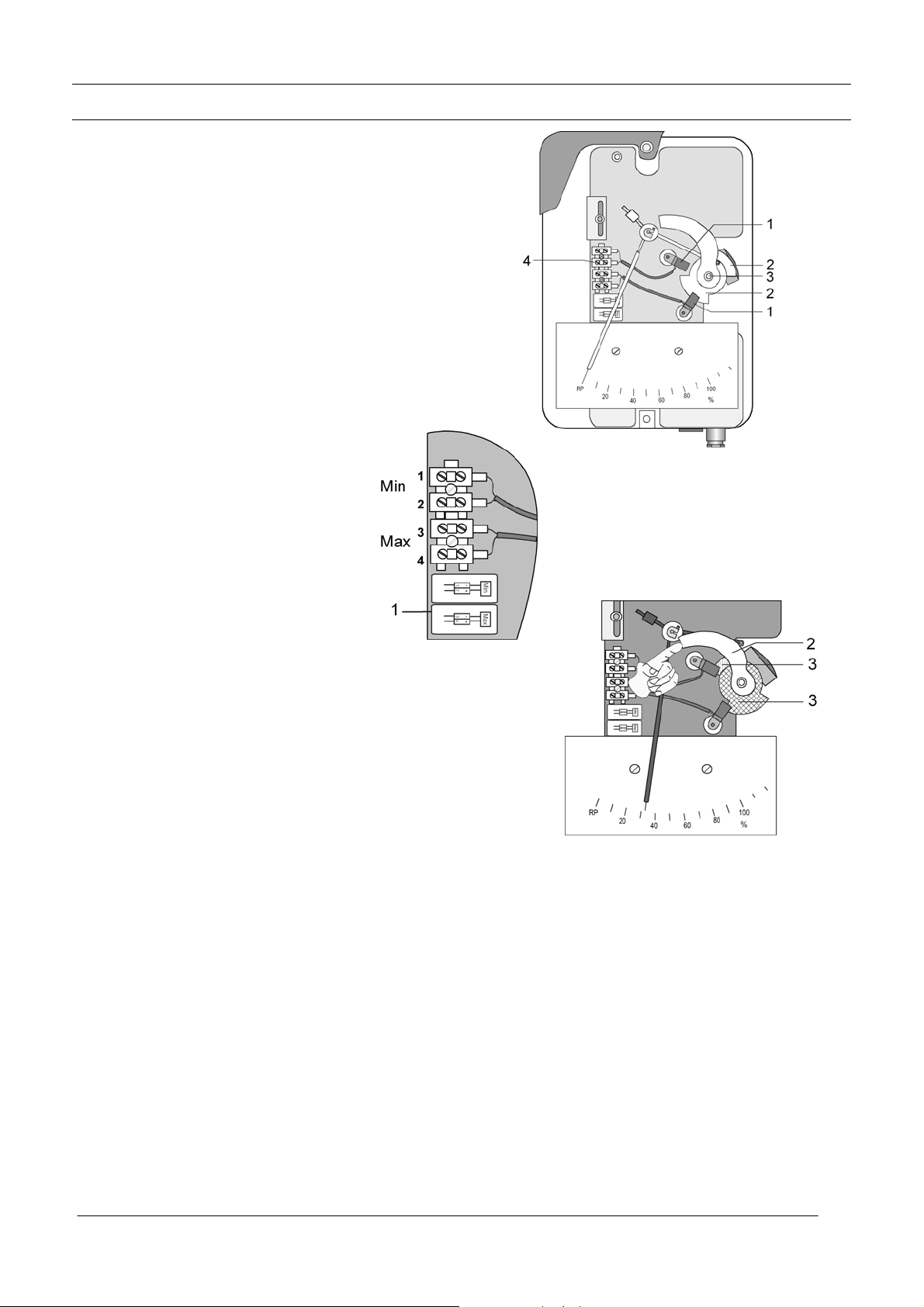
8 Limit switches
Description
The variable area flowmeter H54 can be equipped with
a maximum of two electronic limit switches.
The limit switch functions with a slot-type initiator (1) which is
operated inductively through a metal vane (2).
Contact types:
SC3,5-N0-Y 2-wire technology (NAMUR)
SJ3,5-SN 2-wire technology safety-oriented
SJ3,5-S1N 2-wire technology safety-oriented (inverted)
8.1 Electrical connection
SC3,5-N0-Y, SJ3,5-SN, SJ3,5-S1N:
Limit switch Min Terminal 1 Limit switch Min Terminal 2 +
Limit switch Max Terminal 3 Limit switch Max Terminal 4 +
The label (1) shows the type of contact (1).
8.2 Setting
The limit switches K1 and K2 are set individually from each other
as normally open or normally close!
Lift the cam disk (2) and set the pointer at the switch point.
The metal vanes (3) are set via slipping clutch.
8.3 Technical data of limit switches
Technical data 2-wire 2-wire 2-wire
SC3,5-N0-Y SJ3,5-SN SJ3,5-S1N
NAMUR NAMUR NAMUR
Switching element function NC contact NC contact NO contact
Nominal voltage U0 8 V 8V 8V
Power consumption:
Pointer vane not detected ≥ 3 mA ≥ 3 mA ≤ 1 mA
Pointer vane detected ≤ 1 mA ≤ 1 mA ≥ 3 mA
An isolating switching amplifier, e.g. Pepperl + Fuchs Series KF .. -SR2 ..., is required in order to operate the
SC3,5-N0-Y limit switch (refer to the chapter on the spare part list).
SJ3,5-SN and SJ3,5-S1N limit switches in 2-wire technology safety-oriented are connected to a safety-oriented
isolating switching amplifier, e.g. Pepperl & Fuchs K… –SH- ... (large S on the front)
12 H54 Installation and operating instructions
Page 13
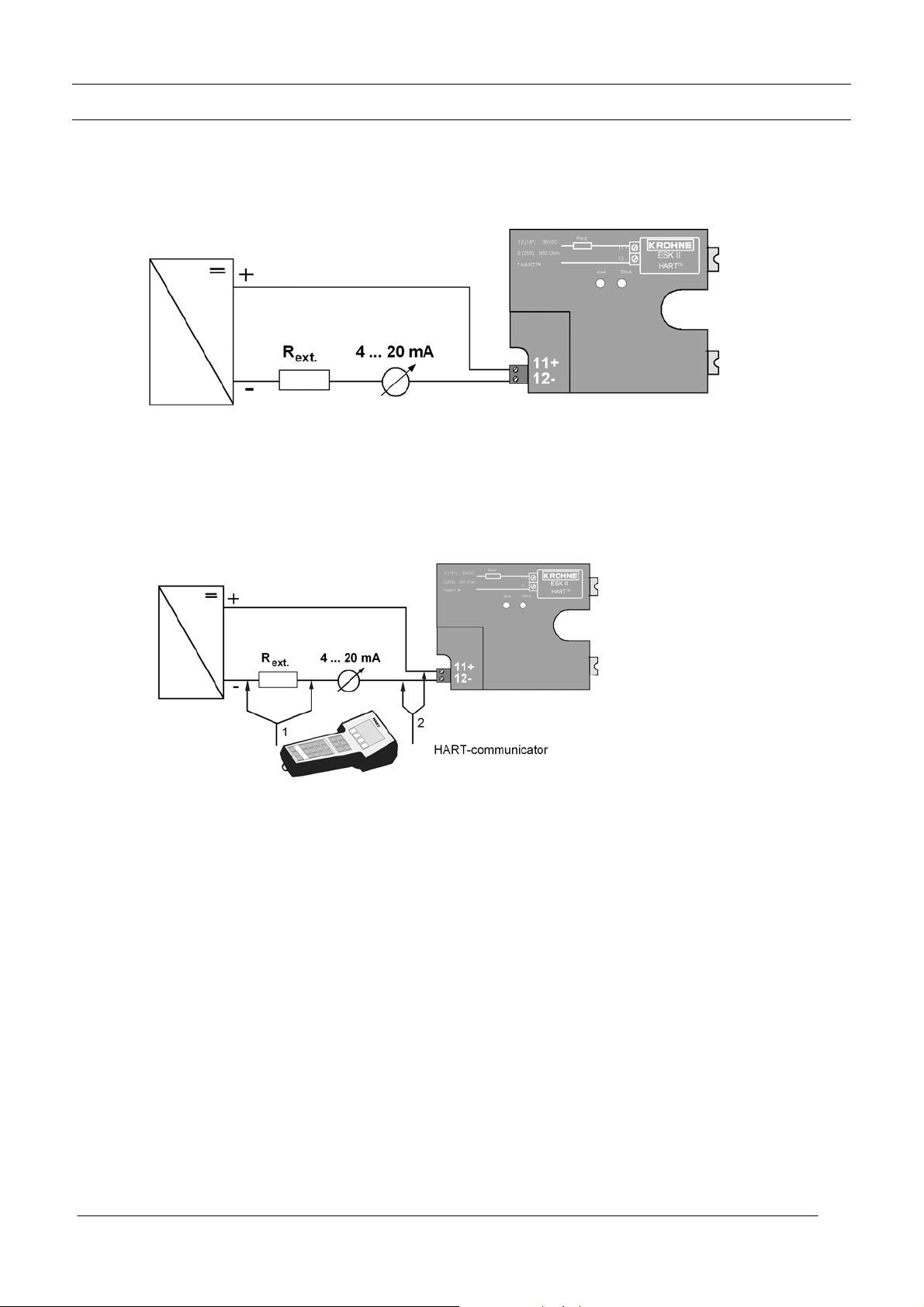
9 Electrical signal output ESK II
9.1 Electrical connection
The connecting terminals of the M9 display have a pluggable design and can be removed in order to
connect the lines.
9.2 HART
HART
When HART
measured value transfer (4...20mA).
Exception at Multidrop operation. In Multidrop operation a maximum of 15 instruments with HART
function can be operated in parallel, whereby their current outputs are switched inactive (approx. 4 mA).
If a HART
used, the resistor which is connected in series (R
In this type of operation the auxiliary power must amount to at least 18 V. The communicator or the PC
is connected as shown in the drawing above.
It can be operated optionally via the connecting terminals of the ESK II (2) or via an external resistance
(1) connected in series. The counter cannot be read out or operated by means of HART
communication!
TM
communication with the ESK II
TM
communication is not compellingly required in order to operate the ESK II.
TM
communication is carried out with the ESK II, this does not by any means impair analog
TM
communicator (type Fisher Rosemount, Model 275) or a PC with HART
) has to exceed 250 Ohms.
ext.
TM
modem is
TM
TM
9.3 Technical data of ESK II
Auxiliary power 12 (18 * ) to 30 V DC
Measurement signal 4.00 to 20.00 mA for 0 to 100 % flow value
> 20.8 mA for alarm status
Auxiliary power influence < 0.1%
Dependency on external resistance < 0.1%
Temperature influence < 5 µA / K
Max. external resistance / load 0 (250 * ) to 800 Ohms
* These values are to be observed as minimum values during HART
TM
communication.
13 H54 Installation and operating instructions
Page 14

10 Electrical signal output ESK3-PA
10.1 Bus cable
The statements of the FISCO model only apply if the bus cable used fullfills the following specifications:
R´ = 15...150 Ohm/km
L´ = 0.4...1 mH/km
C´ = 80...200 nF/km.
10.2 Shielding and grounding
In order to ensure optimum electromagnetic compatibility of systems it is very important that the system
components, and in particular the bus cables which connect the components, are shielded and that
these shields form an electrically unbroken envelope as far as possible.
10.3 PROFIBUS-PA connection
For the connection of the bus cable refer to the adjacent figure.
Connect the cable conductors to D and D- (polarity reversal
does not have any influence). The cable shield should be connected
with minimum length to the functional grounding FE.
10.4 Technical data of the ESK3-PA
Hardware to IEC 1158-2 and the FISCO model
Supply voltage via 2-wire bus connection: .........9 to 32 V DC
Basic current .......................................................12 mA
Starting current ...................................................< Basic current
FDE (fault drop electronics) ................................< 18 mA
Accuracy to VDI/ VDE 3513................................1.6
Measured value resolution..................................< 0.1% of upper range value
Temperature influence........................................< 0.05% / K of upper range value
Software
GSD ..................................(device master file) is supplied on a diskette
or via Internet www.krohne.com
Device profile ....................Complete implementation of Profile B, V3.0
Function blocks
Flow rate (AI0) ..................Optionally for volume or mass rate of flow
Default units: Qv [m3/h]; Qm [kg/h]
D
D
FE
Counter (TOT0).................Volume counter Default unit: [m3]
Counter (TOT1).................Mass counter Default unit: [kg]
Address range...................0-126, default 126 ("Set slave address" is supported)
SAPs .................................Service_Access_Points 1
DD ..................................... Device Description DD for PDM
Operation ..........................Via PROFIBUS PA (no local operation at the instrument)
14 H54 Installation and operating instructions
Page 15

11 Maintenance
The flowmeter is also to be inspected for soiling, corrosive erosion and mechanical wear or damage to the
measuring tube and the display in the context of the routine operational maintenance of the installation and the
pipelines. We recommend at least annual inspections. In order to clean the instrument remove it from the
pipeline.
Note
Pressurized lines have to be relieved before the measuring unit is removed.
Corresponding safety precautions with regard to residual liquids in the measuring unit in case of instruments
which are used to measure aggressive media.
New seals must always be used when remounting the measuring unit in the pipeline.
Electrostatic charges are to be avoided when the surfaces (e.g. viewing window) are cleaned!
Information on returning instruments
Your instrument has been manufactured carefully
and tested several times. If installed and operated in
accordance with these instructions your instrument
will rarely present any problems. Should you
nevertheless need to return an instrument for
checking or repair, please pay strict attention to the
following points:
Due to statutory regulations concerning protection
of the environment and safeguarding the health and
safety of our personnel, KROHNE may only handle,
test and repair returned instruments that have been
in contact with liquids if it is possible to do so
without risk to personnel and environment.
This means that KROHNE can only service your
device if it is accompanied by a certificate in line
with the following model confirming that the device
is safe to handle.
If the instrument has been operated with toxic,
caustic, flammable or water-endangering liquids,
you are kindly requested:
- To check and ensure, if necessary by rinsing
or neutralizing, that all the cavities in
the instrument are free from such dangerous
substances. (Directions on how you can find out
whether the primary head has to
be opened and flushed out and neutralized
are obtainable from KROHNE on request.)
- To enclose a certificate with the device confirming
that the device is safe to handle and
stating the liquid used.
KROHNE regret that we cannot service your device
unless it is accompanied by such a certificate and
thank you for your understanding.
15 H54 Installation and operating instructions
Page 16

Form for returning the instrument
Company: ...................................................... Address: .......................................................................
Department: .................................................. Name: ..........................................................................
Tel. No.: ........................................................ Fax. No.: ......................................................................
The enclosed instrument
Type: ...............................................................................................................................................................
KROHNE Order No. or Series No.:.................................................................................................................
has been operated with the following process liquid: .....................................................................................
Because this process liquid is water-endangering * / toxic * / caustic * / flammable *
we have
- Checked that all cavities in the instrument are free from such substances *
- Flushed out and neutralized all cavities in the instrument *
(* delete where not applicable)
We confirm that there is no risk to man or environment through any residual liquid contained in the instrument.
Date: ............................................................. Signature .......................................................................
Company stamp:
H54 Installation and Operating Instructions
16
 Loading...