

Page 1
Supplementary instructions
Supplementary instructions
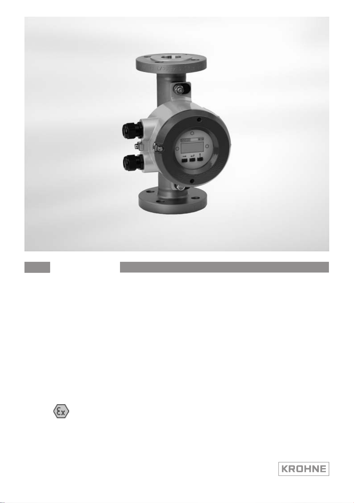
H250 M10
H250 M10
H250 M10H250 M10
Ex supplementary instructions
Equipment category II 3 D
Supplementary instructions Supplementary instructions
© KROHNE 03/2011 - 4001348101- MA H250/M10-Ex-II3G-AD R01 en
Page 2

CONTENTS
H250 M10
1 Safety instructions 3
1.1 General notes ................................................................................................................... 3
1.2 EC conformity ................................................................................................................... 3
1.3 Safety instructions............................................................................................................ 3
2 Device description 4
2.1 Device description ............................................................................................................ 4
2.2 Description code............................................................................................................... 4
2.3 Marking............................................................................................................................. 5
2.4 Flammable products ........................................................................................................ 6
2.5 Equipment category .........................................................................................................6
2.6 Protection types................................................................................................................ 6
2.7 Ambient temperature / temperature classes.................................................................. 7
2.8 Electrical data................................................................................................................... 8
3 Installation 9
3.1 Installation........................................................................................................................ 9
3.2 Special Conditions ............................................................................................................ 9
4 Electrical connections 10
4.1 General notes ................................................................................................................. 10
4.2 Power supply .................................................................................................................. 10
4.3 Inputs / outputs .............................................................................................................. 10
4.4 Earthing and equipotential bonding ............................................................................... 11
5 Operation 12
5.1 Start-up........................................................................................................................... 12
5.2 Operation ........................................................................................................................ 12
5.3 Electrostatic charge .......................................................................................................12
6 Service 13
6.1 Maintenance ................................................................................................................... 13
6.2 Dismantling .................................................................................................................... 14
2
www.krohne.com 03/2011 - 4001348101- MA H250/M10-Ex-II3G-AD R01 en
Page 3
H250 M10
1.1 General notes
These additional instructions apply to explosion-protected versions of the H250/M10 variable
area flowmeter with the designation II 3 D. They complement the Installation and Operating
Instructions for the non-explosion protected versions.
The information given in these Instructions contains only the data relevant to Category 3
explosion protection. The technical details given in the Installation and Operation Instructions for
the non-explosion protected versions apply unchanged unless excluded or superseded by these
Instructions.
1.2 EC conformity
The manufacturer declares with the EC Declaration of Conformity on his own responsibility
conformity with the protection goals of Directive 94/9/EC for use in hazardous areas with dust.
The assessment was made according to Directive 94/9/EC, Annex VIII (module "Internal
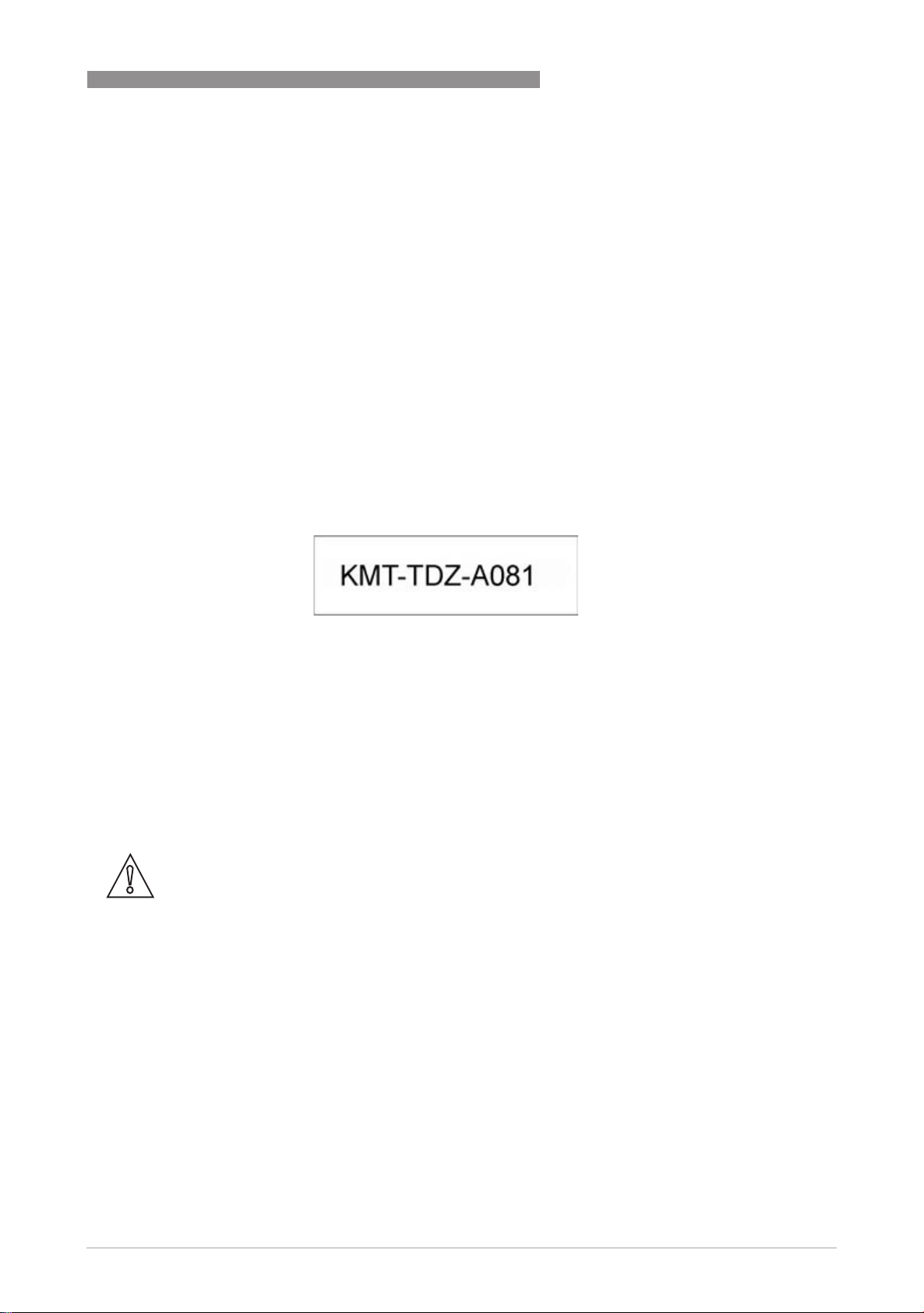
production control"), and is registered in-house under
SAFETY INSTRUCTIONS 1
This registration is also provided on the nameplate.
1.3 Safety instructions
Assembly, installation, start-up and maintenance may only be performed by personnel trained in
explosion protection!
CAUTION!
The operator respectively his agent is responsible to follow further standards, directives or laws
if required due to operating conditions or place of installation. This applies particularly for the
use of easy detachable process connections such as SMS or Clamp when measuring flammable
mediums.
www.krohne.com03/2011 - 4001348101- MA H250/M10-Ex-II3G-AD R01 en
3
Page 4
2 DEVICE DESCRIPTION
2.1 Device description
Variable area flowmeters measure and display the volume flow of flammable and nonflammable gases and liquids. The display unit contains a 4...20 mA signal output with optional
HART® communication, two programmable electronic switch outputs and a reset input.
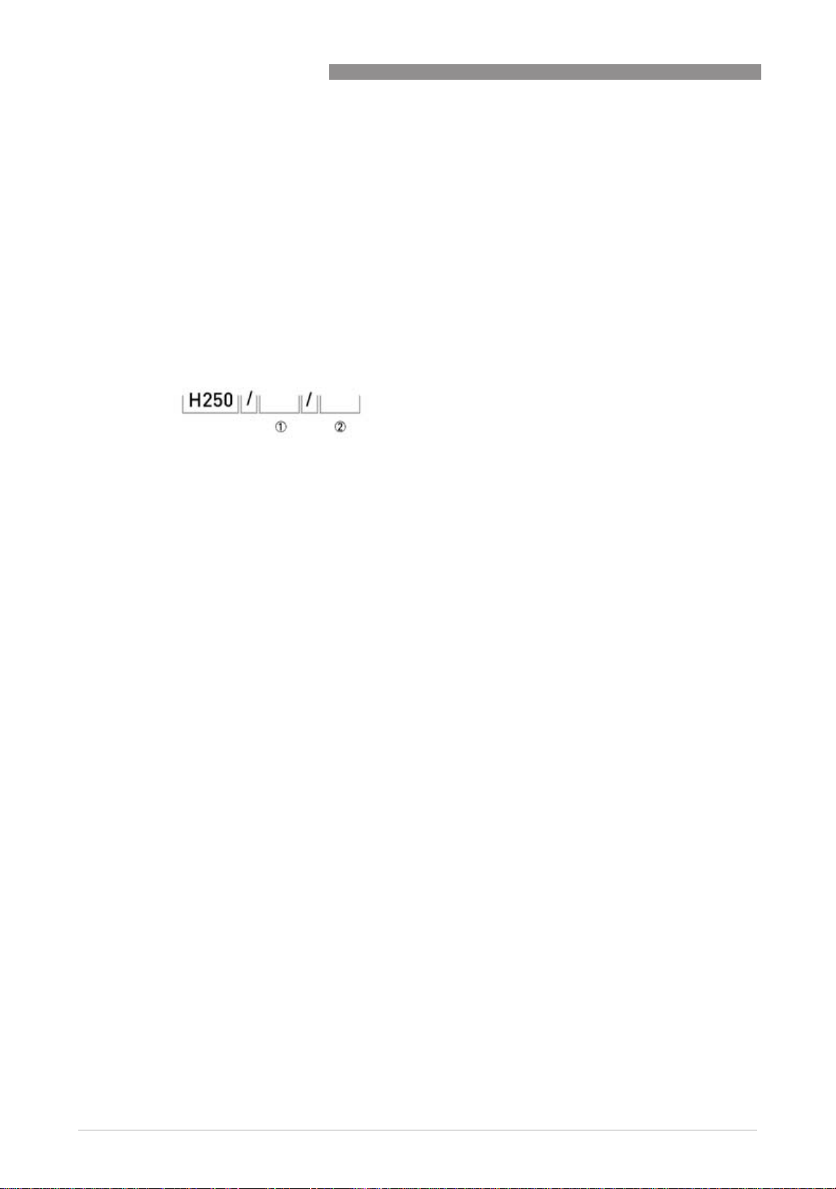
2.2 Description code
The safety description code * consists of the following elements:
1 Materials / versions
RR - Stainless Steel
C - PTFE or PTFE/ceramics
HC - Hastelloy
Ti - Titanium
F - aseptic version (food)
2 Series of indicators
M10 - Converter M10
H250 M10
* positions which are not needed are omitted (no blank positions)
4
www.krohne.com 03/2011 - 4001348101- MA H250/M10-Ex-II3G-AD R01 en
Page 5
H250 M10
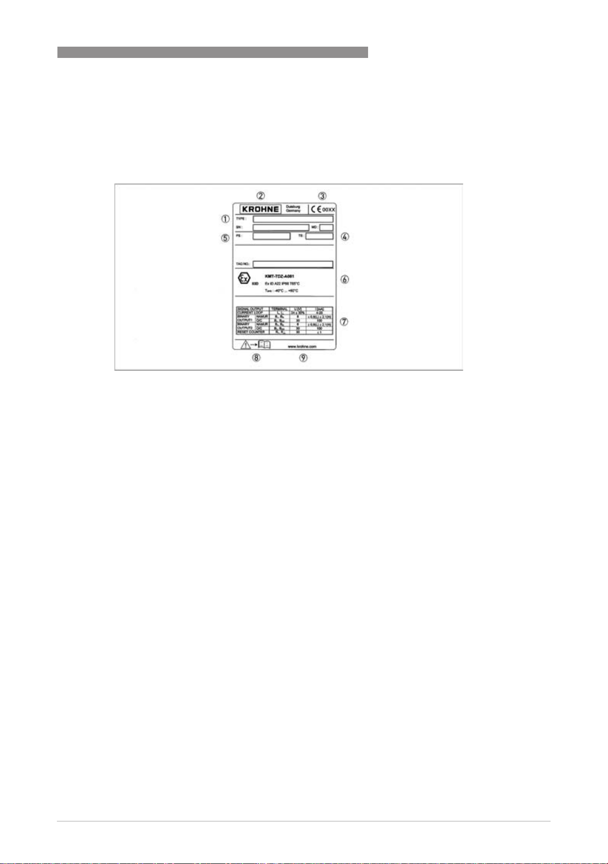
2.3 Marking
The marking of the entire device is on the display, where the following identification plate can be
found.
DEVICE DESCRIPTION 2
1 Device type according to description code
2 Manufacturer
3 Identification number of the notified body, Pressure Equipment Directive [PED]
4 Sizing data: temperature & pressure rating
5 PED data
6 Ex data
7 Electrical connection data
8 Note manual
9 KROHNE website
Additional markings on the device:
• SN - serial number
• SO - sales order / item
• PA - KROHNE order
• Vxxx - product configurator code
• AC - article code
www.krohne.com03/2011 - 4001348101- MA H250/M10-Ex-II3G-AD R01 en
5
Page 6

2 DEVICE DESCRIPTION
2.4 Flammable products
Atmospheric conditions
An explosive atmosphere is a mixture of air and flammable gases, vapours, mists or dusts under
atmospheric conditions. The following values define it:
= -20...+60°C / -4...+140°F and P
T
atm
Outside of this range, no key data are available as to ignition behaviour for most mixtures.
Operating conditions
Variable area flowmeters operate outside of atmospheric conditions, which means that
explosion protection according to Directive 94/9/EC (ATEX) – regardless of the zone assignment
– is fundamentally not applicable due to the lack of key safety data for the interior of the
measuring section.
CAUTION!
Operation with flammable products is only permitted as long as no explosive fuel/air mixture
builds up on the inside of the flowmeter under operating conditions. The operator is responsible
for ensuring that the flowmeter is operated safely as regards the temperature and pressure of
the products used. In case of operation with flammable products the measuring units must be
included in the periodic pressure tests of the system. When using the device version H250/C...
(PTFE-liner, nonconductive) the min. conductivity of the medium must be 10
avoid the electrostatic charge.
= 0.8...1.1 bar.
atm
H250 M10
-8
S/m, in order to
2.5 Equipment category
The flowmeters are designed in category II 3D according to EN61241-0:2006 and EN 612411:2004 for use in zone 22.
2.6 Protection types
The variable area flowmeter is designed with protection type "Protection by enclosure"
according to EN 61241-1:2004. Dust protection is guaranteed by the use of a housing which
provides appropriate protection against penetration by dust.
The marking is: II 3 D Ex tD A22 IP66 T65
The marking contains the following information:
The marking contains the following information:
The marking contains the following information:
The marking contains the following information:The marking contains the following information:
II
II Group II explosion protection
IIII
3333 Equipment category 3
DDDD Dust explosion protection
tD
tD Protection by enclosures
tDtD
A22
A22 Surface temperature according to method A, use in zone 22
A22A22
IP66
IP66 Foreign bodies and water pollution control
IP66IP66
T65
T65°C
C Maximum surface temperature of the converter housing without dust coating at ambient
T65T65
CC
II 3 D Ex tD A22 IP66 T65°C
II 3 D Ex tD A22 IP66 T65II 3 D Ex tD A22 IP66 T65
temperature 60°C / 140°F and product temperature 60°C / 140°F
C
CC
6
www.krohne.com 03/2011 - 4001348101- MA H250/M10-Ex-II3G-AD R01 en
Page 7

H250 M10
2.7 Ambient temperature / temperature classes
Because of the influence of the temperature of the product, no fixed temperature class is
assigned to variable area flowmeters. In fact, the temperature class of a device is a function of
the temperature of both the product and the environment. The classification is outlined in the
following tables.
The tables take into account the following parameters:
• Ambient temperature T
• Product temperature T
• Nominal DN
• Heat resistance of the connecting cable
INFORMATION!
The maximum permissible product temperatures listed in the tables are valid under
the following conditions:
•
The measuring device is installed and operated in accordance with the installation
instructions in the installation and operating manual.
•
It must be ensured that the flowmeter is not heated by the effects of additional heat radiation
(sunshine, neighbouring system components) and thus operated above the permissible
ambient temperature range.
•
Insulation must be limited to the piping.
Unobstructed ventilation of the indicator part must be ensured.
amb.
m
DEVICE DESCRIPTION 2
For certain device version, lower values apply due to differing boundary conditions (e.g. lining
materials).
Here the user should consult the technical data sheet.
Maximum permitted product temperature °C
Maximum permitted product temperature T
operating temperature of the cable T
Ambient temp. Cable T
-40...+40 180 200 200
-40...+50 135 190 200
-40...+60 85 145 200
max
=70°C T
max
(°C) as a function of the maximum continuous
m
=80°C Cable T
max
max
=90°C
Maximum permitted product temperature °F
Maximum permitted product temperature T
operating temperature of the cable T
Ambient temp. Cable T
-40...+104 356 392 392
-40...+122 275 374 392
-40...+140 185 293 392
max
= 158°F Cable T
max
(°F) as a function of the maximum continuous
m
= 176°F Cable T
max
max
=194°F
www.krohne.com03/2011 - 4001348101- MA H250/M10-Ex-II3G-AD R01 en
7
Page 8

2 DEVICE DESCRIPTION
For use in areas with flammable dust it should be noted that the indicated maximum surface
temperature of T65°C at an ambient temperature of 60°C / 140°F and a product temperature of
60°C / 140°F is valid without a dust coating. For higher product temperatures the maximum
surface temperature is determined by the product.
2.8 Electrical data
Circuit Rated voltage Nominal current
Optional switching outputs NAMUR 8V DC 1mA - 3mA
Current output 4-20 mA 24V DC ± 25% 4mA - 20mA
Reset input 9V DC - 30V DC < 2mA
The insulation of the flowmeter is measured according to EN 61010-1:2001. The following
ratings are taken into account:
Open-collector-PNP 24V DC ±
25%
H250 M10
1mA - 100mA
with HART communication
• Overvoltage category II
• Pollution degree 2 (inside device on printed circuit boards)
8
www.krohne.com 03/2011 - 4001348101- MA H250/M10-Ex-II3G-AD R01 en
Page 9

H250 M10
3.1 Installation
Installation and setup must be carried out according to the applicable installation installation
standards (e.g. EN 60079-14) by qualified personnel trained in explosion protection. The
information given in the Installation and Operation Instructions and the Supplementary
Installation and Operation Instructions must always be observed.
Variable area flowmeters must be installed in such a way that
• There is no danger from mechanical impact effects.
• There are no external forces affecting the indicator part.
• The device is accessible for any visual inspections that are necessary, and can be viewed from
all sides.
• The nameplate is clearly visible.
• It can be operated from a location with secure footing.
CAUTION!
The manufacturer is not liable for any damage resulting from improper use or use other than the
intended purpose. This applies in particular to hazards due to insufficient corrosion resistance
and suitability of the materials in contact with product.
INSTALLATION 3
3.2 Special Conditions
Cable entries / Blanking plugs
Cable entries / Blanking plugs
Cable entries / Blanking plugsCable entries / Blanking plugs
The variable area flowmeter is optionally equipped with one conduit entry and one blind plug or
two conduit entries. These elements ensure protection against foreign bodies and water
(protection category) IP66 according to EN 60529 in the temperature range of T
40°C...+100°C / -40...+212°F. The conduit entries are sealed with a plug. The plugs should be
replaced with suitable connecting cables. The nominal diameter range of the conduit entries is
marked on the plugs.
A choice of the following nominal diameters is available:
• Plugs with marking 13,5: Nominal diameter 6...12 mm / 0.24...0.47 inch
• Plugs with marking 16: Nominal diameter10...14 mm / 0.39...0.55 inch
Electronics compartment lock
Electronics compartment lock
Electronics compartment lockElectronics compartment lock
Close the variable area flowmeter during operation. The cover for the electronics compartment
is secured by means of a lock. Use an SW3 Allen key to turn the screw.
amb
= -
www.krohne.com03/2011 - 4001348101- MA H250/M10-Ex-II3G-AD R01 en
9
Page 10

4 ELECTRICAL CONNECTIONS
4.1 General notes
The signal circuits are electrically connected in the buit-in terminal compartment of the signal
converter.
Unused conduit entries should be closed using approved blind plugs and seals. Ensure that the
seals are tight.
The connecting cables should be selected according to the applicable installation standards (e.g.
EN 60079-14) and the maximum operating temperature. The outside diameter of the connecting
cables must be matched to the sealing area of the conduit entry/entries. The connecting cables
must be fixed and laid in such a way as to be sufficiently protected against damage.
Before connecting or disconnecting the electric connecting cable of the device, ensure that all of
the cables leading to the signal converter are de-energised relative to each other and to the
reference potential of the hazardous area. This also applies to earthing conductors (FE) and
equipotential bonding conductors (PA).
All cores that are not used must be securely connected to the earth potential of the hazardous
area or carefully insulated against each other and against ground (test voltage ≥ 500 V
H250 M10
).
eff
4.2 Power supply
The variable area flowmeter does not require any separate power supply. The required supply
for the built-in electronics is provided via the 4...20mA current output.
4.3 Inputs / outputs
The signal circuits of the variable area flowmeter may only be connected to downstream devices
or circuits that satisfy the requirements of protective extra-low voltage (PELV). The terminal
assignment of the equipment is described in the standard installation and operating
instructions.
10
www.krohne.com 03/2011 - 4001348101- MA H250/M10-Ex-II3G-AD R01 en
Page 11

H250 M10
4.4 Earthing and equipotential bonding
The signal converter shall be connected to the equipotential bonding system of the hazardous
area via the external grounding connection on the signal converter housing. The measuring unit
and the signal converter are electrically connected via an equipotential bonding conductor.
Any existing cable shields should be connected to earth according to applicable installation
regulations (EN 60079-14). A terminal connection in the terminal compartment permits a short
way earthing of the cable shields.
ELECTRICAL CONNECTIONS 4
1 External grounding connection
2 Internal grounding connection
www.krohne.com03/2011 - 4001348101- MA H250/M10-Ex-II3G-AD R01 en
11
Page 12

5 OPERATION
5.1 Start-up
Start-up is only permitted when the variable area flowmeter:
• is correctly installed in the system and connected.
• has been checked for the proper state with regard to its installation and connection
requirements.
The user of the system must have it checked before start-up in compliance with the national
regulations for checks before startup.
If the device needs to be configured due to the existence of an explosive dust atmosphere, this
can be done using the supplied programming magnets. There is no need to open the housing as
it can be done through the glass window of the electronics compartment or digitally via the
signal output (HART interface).
5.2 Operation
Variable area flowmeters must be operated in such a way that they remain within the maximum
and minimum permissible temperatures and pressures and the electrical limit values.
H250 M10
Variable area flowmeters may only be operated if the equipment parts necessary for safety are
effective in the long run, and are not rendered inoperable during operation.
During operation it is only permitted to open the indicator if no explosive atmosphere is present.
5.3 Electrostatic charge
In order to avoid ignition hazards due to electrostatic charge, variable area
flowmeters may not be used in areas where the following appear:
• processes that generate large charges,
• machines with friction and cutting processes,
• spraying of electrons (e.g. in the vicinity of electrostatic painting systems),
• dust carried by compressed air.
12
www.krohne.com 03/2011 - 4001348101- MA H250/M10-Ex-II3G-AD R01 en
Page 13

H250 M10
6.1 Maintenance
Maintenance work of a safety-relevant nature within the meaning of explosion protection may
only be carried out by the manufacturer, his authorised representative or under the supervision
of authorised inspectors.
For systems in hazardous areas, regular tests are required in order to maintain the proper
condition.
The following checks are recommended:
• Checking the housing, the cable entries and the feed lines for corrosion and/or damage.
• Checking the measuring unit and the piping connections for leakage.
• Checking the measuring unit and the indicator for dust deposits.
Following any maintenance work on the converter, re-grease the cover thread including the
cover seals with a non resinous, acid-free, all purpose grease.
SERVICE 6
www.krohne.com03/2011 - 4001348101- MA H250/M10-Ex-II3G-AD R01 en
13
Page 14

6 SERVICE
6.2 Dismantling
Exchanging the built-in equipment
Due to the modular design of the variable area flowmeter, it is possible to replace a complete
signal converter and display with an identical spare part in accordance with safety guidelines.
CAUTION!
There may be a loss of measuring accuracy!
Exchanging the entire device
Removal and installation are the responsibility of the operator.
Before disconnecting the electric connecting cable of the device, make sure that all cables
leading to the indication unit are isolated from the ground of the hazardous area. This also
applies to functional earthing conductors (FE) and equipotential bonding conductors (PA).
Faulty prisms (spacers) between the measuring tube and the display housing should be
replaced.
H250 M10
CAUTION!
•
Pressurized pipes have to be depressurized before removing the measuring unit.
•
In the case of environmentally critical or hazardous products, appropriate safety precautions
must be taken with regard to residual liquids in the measuring unit.
•
New gaskets have to be used when re-installing the device in the piping.
14
www.krohne.com 03/2011 - 4001348101- MA H250/M10-Ex-II3G-AD R01 en
Page 15

H250 M10
SERVICE 6
.
www.krohne.com03/2011 - 4001348101- MA H250/M10-Ex-II3G-AD R01 en
15
Page 16

KROHNE product overview
• Electromagnetic flowmeters
• Variable area flowmeters
• Ultrasonic flowmeters
• Mass flowmeters
• Vortex flowmeters
• Flow controllers
• Level meters
• Temperature meters
• Pressure meters
• Analysis products
• Measuring systems for the oil and gas industry
• Measuring systems for sea-going tankers
Head Office KROHNE Messtechnik GmbH
Ludwig-Krohne-Str. 5
D-47058 Duisburg (Germany)
Tel.:+49 (0)203 301 0
Fax:+49 (0)203 301 10389
info@krohne.de
© KROHNE 03/2011 - 4001348101- MA H250/M10-Ex-II3G-AD R01 en - Subject to change without notice.
The current list of all KROHNE contacts and addresses can be found at:
www.krohne.com
 Loading...