

Page 1
02/98
CORIMASS G+ Class
Installation and
Operating
Instruction s
Single straight tube mass flow meter
MFM 4085 K/F
Page 2

How to use these installation and operating instructions
For easy reference these Instructions are divided into four parts.
Only Part A (page 3) is needed for installation and initial start-up.
All CORIMASS mass flowmeters of t he G-S eries are fact ory set to your or der sp ecif ication s .
Part A Install flowmeter in the pipeline (Sect. 1), connect up (Sect. 2) and power the
flowmeter (Sect. 3).
The system is operational
Part B Operator control and functions of the MFC 085 Signal Converter.
Part C Service and functional checks.
Part D Technical data, dimensions and measuring principle.
Product liability and warranty
The CORIMASS mass flowmeter MFM 4085 is designed for the direct measurement of mass
flow rate, product density and product temperature, and also indirectly enables measurement of
parameters such as tota l mas s, concentration of dissolved substanc es and the volume flow.
For use in hazardous areas, special codes and r egul ations ar e applica ble wh i ch ar e spec i fied
in the special ”Ex installation and operating instructions” (supplied only with hazardous-duty
equipment).
Responsibility as to suitability and intended use of our instruments rests solely with the
purchaser.
Improper installation and operation of the flowmeters may lead to loss of warranty.
In addition, the ”general conditions of sale” forming the basis of the p urch ase agreement a re
applicable.
If you need to return CORIMASS flowmeters to KROHNE, please complete the form on the last
page of this manual and return it with the meter to be repaired. Krohne regrets that it cannot
repair or check your flowmeter unless accompanied by this completed form.
CE / EMC Standards / Approvals
• The Corimass MFM 4085 with the MFC 085 signal converter meet the requirements of the
EU-EMC Directives and bear the CE symbol.
• The Corimass MFM 4085 K -Ex are approved as hazardous duty equipment to the
harmonised European Standards and to Factory Mutual (FM). Further details are given in the
”Ex” supplementary instructions provided only with hazardous-duty equipment.
CE
Technical data subject to change without notice
2
Page 3

Contents
Part AInstallation and Start-up 5 - 24
1. Installation in the pipeline 5
1.1 General principles 5
1.2 Installation Guidelines 5
1.2.1 Mounting location 5
1.2.2 Connecting pipes 6
1.2.3 Mounting figures 8
1.2.4 Installation factor 8
1.2.5 Standard flange sizes for the flow meter 9
1.2.6 Cross talk 10
1.2.7 Recommended piping for use with the G-Meter 10
1.2.8 Inner Pipe diameters of the G-Series 10
1.3 External Heating and Insulation 11
1.3.1 Insulation 11
1.3.2 Electrical Trace Heating 13
1.3.3 Hot Fluid or Steam Heating 14
1.3.4 Heating Up from Cold 15
2. Electrical installation 17
2.1 Location and connecting cables 17
2.2 Connection to power 18
2.3 Inputs and outputs 18
2.4 Connection of Remote Meters 20
3. Start-up 21
3.1 Factory set parameters 21
3.2 Initial start-up 22
3.3 Installation factor 22
3.4 Zero point adjustment 22
3.5 Programming the converter with a bar magnet 24
Part BMFC 085 Signal Converter 25 - 75
4. Operation of the Signal Converter 25
4.1 Operating and check elements 25
4.2 Krohne Operating Concept 26
4.3 Key functions 27
4.3.1 How to enter programming mode 28
4.3.2 How to terminate programming mode 28
4.4 Table of programmable functions 31
4.5 Reset / Quit Menu - Totalizer reset and status indication acknowledgement 41
4.6 Status messages 43
4.7 Menu variations for systems with other output options 44
5 Descriptions of functions 45
5.1 Zero point adjustment 45
5.2 Low Flow cutoff 47
5.3 Time constant 47
5.4 Pro gramming the display for meas uremen t values 48
5.5 Programming Numeric Data 51
5.6 Setting the current output 52
5.7 Setting the frequency / pulse output 55
5.8 Setting the process alarm output (status) 59
5.9 Setting the control input (binary) 61
5.10 Setting the system control 62
3
Page 4

5.11 Standby function 63
5.12 Density adjustment for maximum measuring accuracy 65
5.13 Specific gravity 69
5.14 User data 71
5.14.1 Programming the display language 71
5.14.2 Password protection of menus 71
5.14.3 Custody transfer protection code 72
5.14.4 Primary head type and tube parameters (CF1-5) 74
5.14.5 Location 75
Part CSpecial options, Functional checks, Service and Order numbers 76 - 95
6. Special options 76
6.1 Use in hazardous areas 76
6.2 Converter with non-standard output options 76
6.3 Concentration measure ments 76
6.4 Converter with Smart / Hart communication option 76
6.5 Converter with RS 485 communication option 77
6.6 Custody transfer option 77
7. Functional checks 77
7.1 Test functions 77
7.1.1 Testing the display 77
7.1.2 Testing current output 78
7.1.3 Testing pulse output 78
7.1.4 Testing alarm output 80
7.1.5 Testing control input 80
7.1.6 Viewing temperature and strain 81
7.1.7 Viewing primary head signal conditions 81
8. Service and Troubleshooting 82
8.1 Threads and ”O” ring of the converter housing lid 82
8.2 Replacing the conver ter el ectroni cs 82
8.3 Change of operating voltage and power fuse F9 83
8.3.1 Replacement of power fuse F9 83
8.3.2 Changing the operating voltage 83
8.4 Turning the display circuit board 84
8.5 Turning the Signal Converter housing 84
8.6 Troubleshooting 85
8.7 Fault finding 88
8.8 Checking the Primary head 91
8.8.1 Compact Meter 91
8.8.2 Remote Meter 92
8.9 Status warnings 93
9. Order numbers 95
Part DTechnical Data, Measurement principle and Block diagram 96 - 104
10. Technical data 96
10.1 Measuring ranges and error limits 96
10.2 Primary head 97
10.3 MFC 085 Signal Converter 98
10.4 Block diagram of Converter MFC 085 101
10.5 Instrument data plate 102
10.6 Dimensions and weights 102
11. Measuring principle 104
12. Software History 104
4
Page 5
Part A Installation and Start-up
1. Installation in the pipeline
1.1 General principles
The MFM 4085 K/F CORIMASS mass flow meter provides high accuracy and excellent
repeatability. Narrow band pass digital filtering, and the mathematically modelled internal
primary head design provides exceptional immunity to external vibratory disturbances from
nearby process equipment. The accuracy of the flow meter is not affected by velocity profile.
The straight single tube means there is a very low risk of cavitation, and no air can be trapped
inside the meter. No back pressure is required at the outlet of the meter. As with all Coriolis
mass flow meters, the CORIMASS is an active device with its own energy source. A good
installation is essential for the high measurement accuracy.
The following installation guidelines are practical to implement, particularly if planned before the
CORIMASS is first installed. For further dimensions or connections, please refer to Section D,
Technical Data.
1.2 Installation Guidelin e s
1.2.1 Mounting location
For the G+ no special mounting requirements are necessary. However, good general
engineering practices for the installation of flow meters should still be observed.
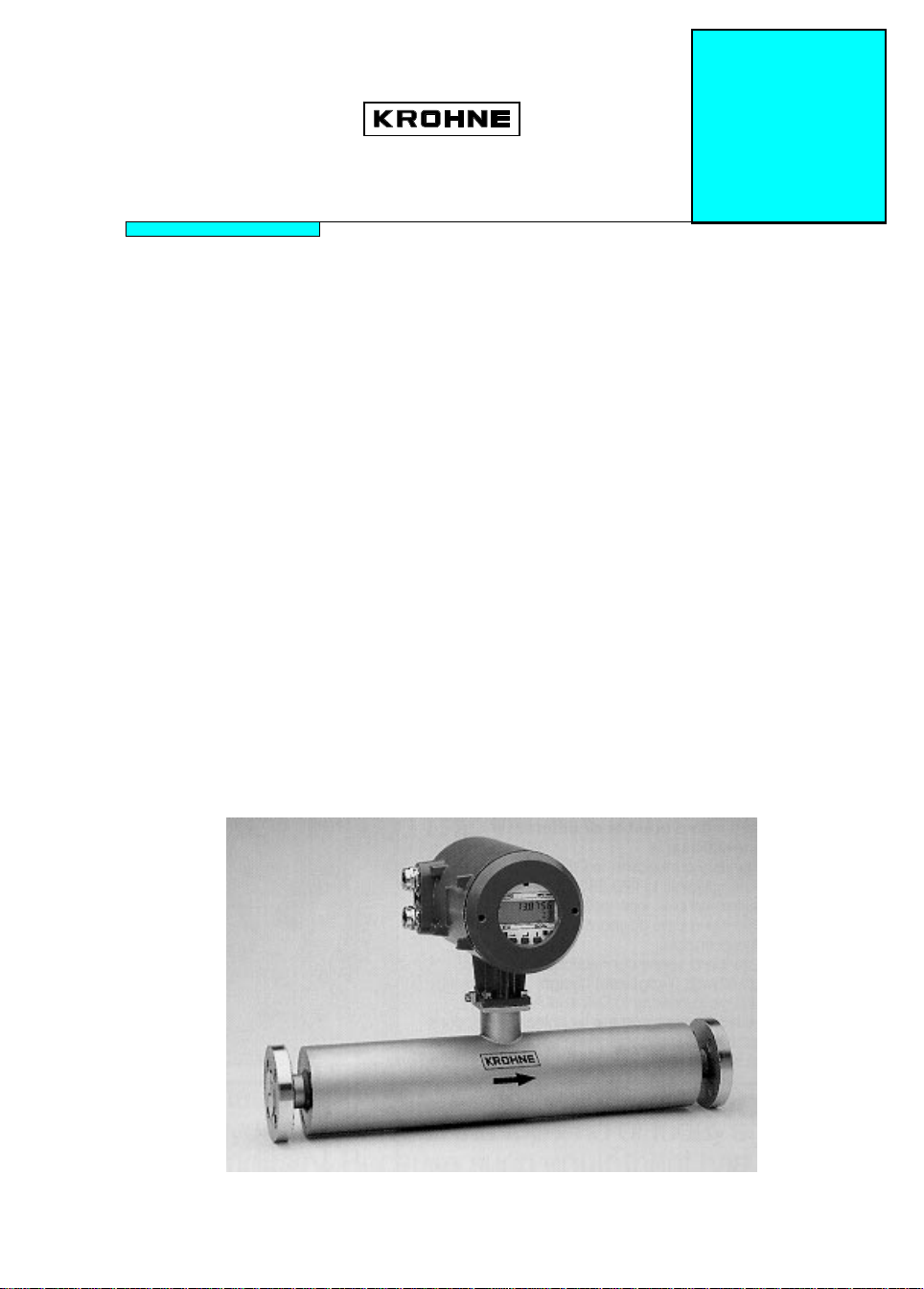
¾
The meter can be installed horizontally, in an upward sloping pipeline or vertically. For best
results, a vertical installation with flow in an upward direction is recommended.
Flow
1.2.2 Connecting pipes
Upward sloping install ation
Vertical instal lation (recommended)
Flow
Figure 1
Horizontal mounting
Flow
5
Page 6
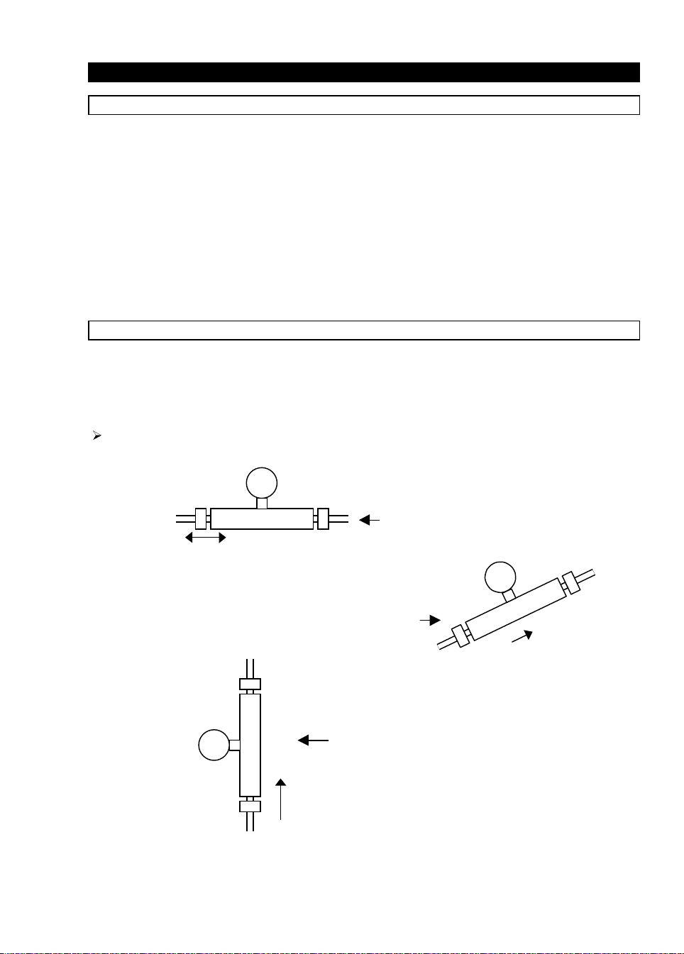
¾
Avoid mounting the meter with long vertical drops after the meter. This could cause
siphoning and cause measurement errors.
Siphoning effect
Figure 2. Avoid long vertical drops
¾
Install meter at least 4 × L downstream of pumps. ( where L = length of the meter )
> 4 × L
Figure 3
¾
Avo id mounting th e meter at t he hig hest p oint in th e pipeline. Air or gas can accumulate
here and cause faulty measurements.
Figure 4
¾
The use of reducers at the flanges is allowed. Extreme pipe size reductions should be
avoided due to possibility of cavitation and gassing. One size up from smallest available
flange size is acceptable.
Figure 5
One size up from standard
6
Page 7
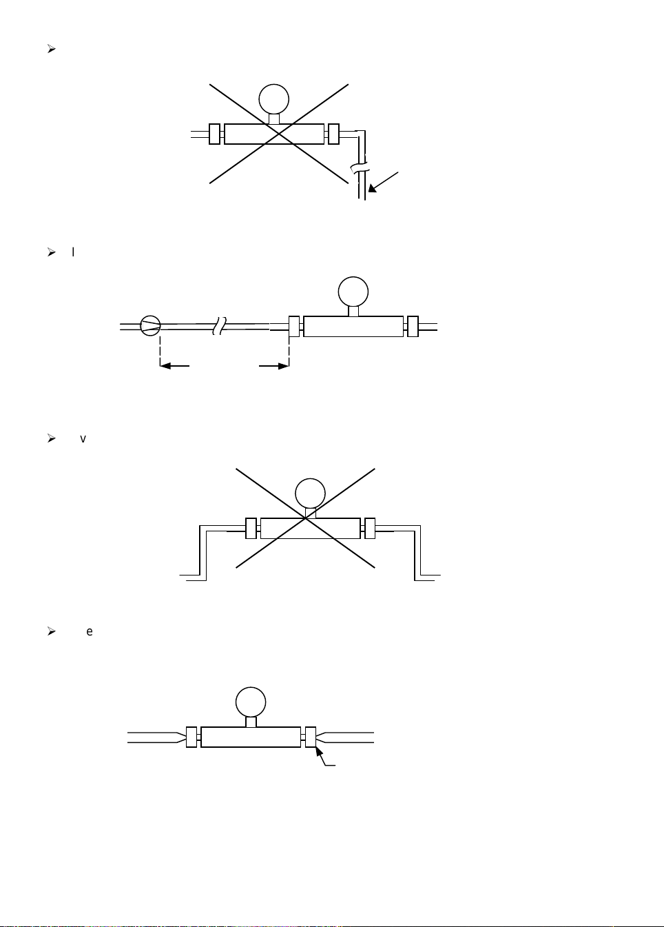
¾
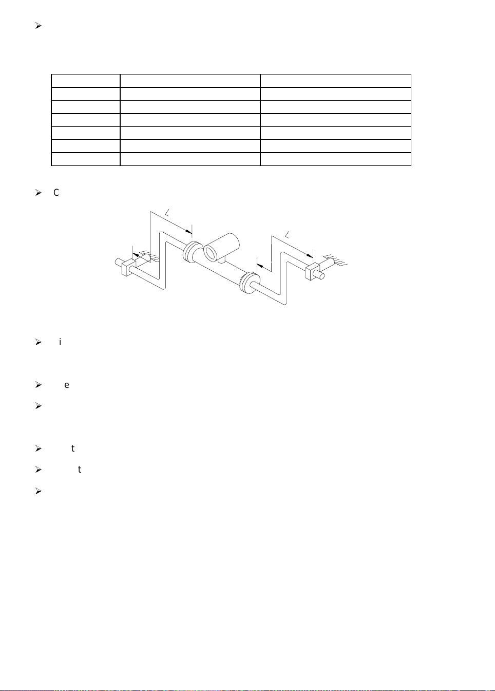
The use of flexible hoses is allowed. For best results the meter should be supported by two
spool pieces and the hoses connected to these spool pieces. For low flow rates (less than
10%) secondary clamps may be required.
L L
Figure 6
Note: See table on next page for information on supports for distances, L.
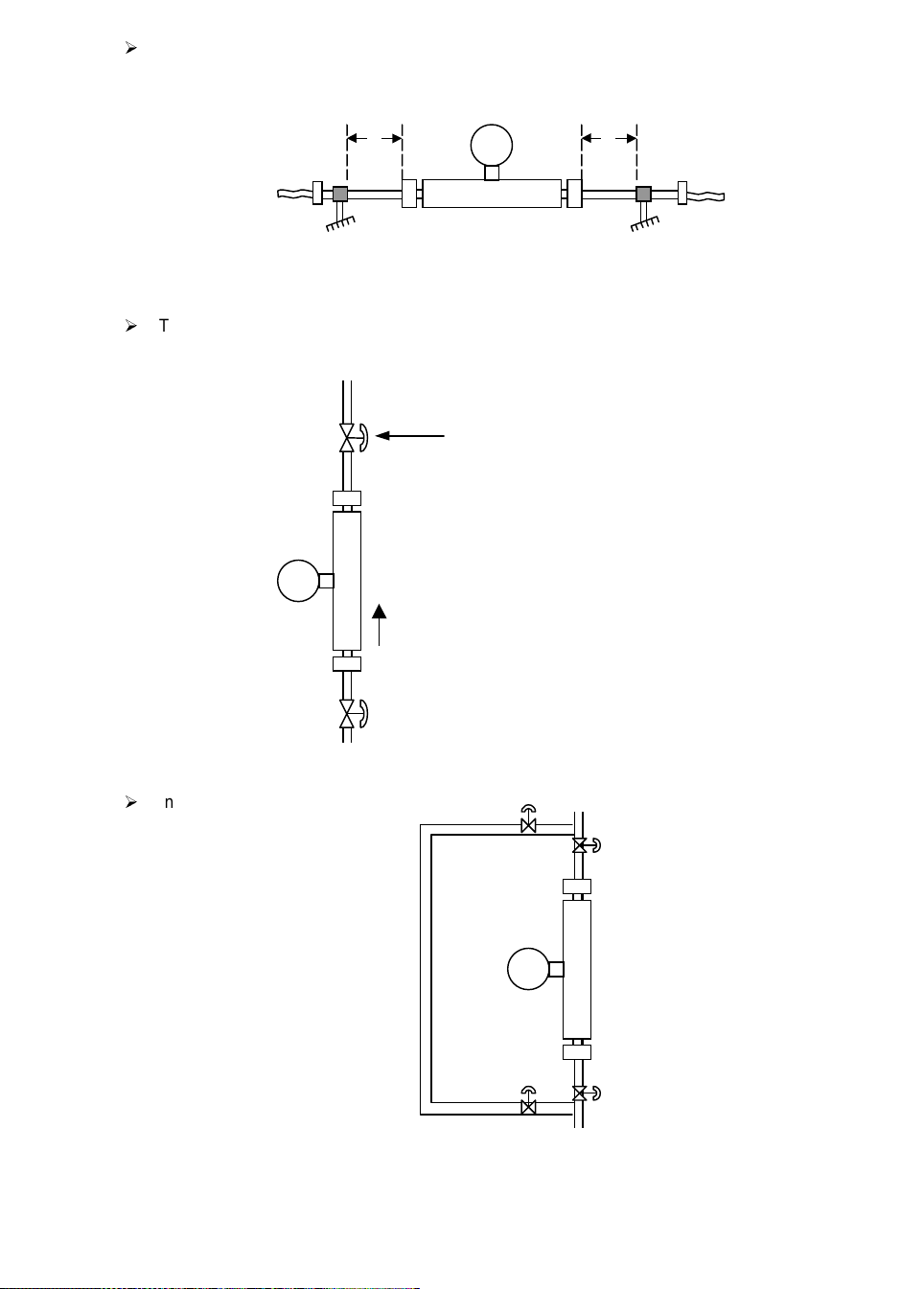
¾
To enable a good zero to be done, it is recommended that a shut-off valve be installed
downstream of the flow meter.
Valve for zeroing flow meter
Flow
The second valve is recommended if the
pump is sw itc hed off to pr event back flow
Figure 7
Figure 7
¾
Installing in a bypass
Figure 8
7
Page 8
¾
Should it become necessary to support the pipework, the following guidelines should be
fol low ed. Do not clamp the meter body or the process pi pework clo ser than di stance L, as
shown in the table below. Due to the weight of the 800 to 3000 G, the pipework should be
supported. Please note minimum support distances as per table.
Meter Size
10 G+ 21
100 G+ 35
300 G+ 48
800 G+ 48
1500 G+ 48 (DN 50) 70 (DN 80)
3000 G+ 48 (DN 80) 60 (DN 100)
L (cm)
8,8
13,8
18,9
18,9
18,9 (2”N.B.) 27,6 (3”N.B.)
18,9 (2”N.B.) 23,7 (3”N.B.)
L (inch)
¾
Connecting pipes may have bends between the meter and supports
Figure 9
¾
Fit valves, sensors, sight glasses, etc. outside the supports if possible.
1.2.3 Mounting fixtures
¾
The connecting pipework must be in a stress free condition.
¾
The meter should fit between the connecting pipe with perhaps 2 - 3 mm (1/8 inch) to spare.
It should not be necessary to force the pipes apart to fit meter. Flanges should be correctly
aligned.
¾
Tighten flange bolts evenly.
¾
Do not fit rigid electrical conduit to the converter housing.
¾
Do not fit supports or any fixtures to any part of the meter or connecting pipework between
meter and supports.
1.2.4 Installation factor
The installation factor feature is unique to the G-Series. This factor (found in menu 2.7.4) is a
dimensionless number between 0 and 999 which is an indication of how well the instrument is
installed and whether the product contained gas bubbles. This is a function of the amount of
energy required to excite the measuring tube to its natural resonant frequency. The auto zero
value (menu 1.1.1 or 3.1.1) should be as low as possible, typically less than 1% for normal
installations and less than 2% for extreme conditions.
8
Page 9

The following values are a guideline to a good installation:
With the meter filled with water, the values should be less than the figure indicated.
Meter Size Installation factor
Non Ex
• Installation factor
Ex
10 G + 20 200
100 G + 10 150
300 G + 20 400
800 G + 20 300
1500 G + 30 300
3000 G + 40 400
• The higher installation factor for Ex instruments is due to the power limiting of the Zener
barriers in the Exciter circuit, and does not mean bad installation.
• Product with higher density or entrained gas will exhibit higher installation factors.
Use the followin g procedur e t o check th e i nstallation fact or. Warm up the electro nics for at l east
30 minutes. Flush the meter with water or product to ensure that all trapped air has been
removed.
Key Display
Line 2
→
↑
→
6 × ↑
→
3 × ↑
→
Fct. (1).0 OPERATOR
Fct. (2).0 TEST
Fct. 2.(1) TEST DISP:
Fct. 2.(7).0 TEST: TRANSD:
Fct. 2.7.(1) SENSOR A
Fct. 2.7.(4) INSTAL:FACT:
Fct. xxx
Display
Line 2
LEVEL
Display of installation factor
3 × ↵
↵
Fct. 2.7.(4) INSTAL:FACT
Display
Not e: Terms in bracket s are flashing on the displ ay.
1.2.5 Standard flange sizes
The following is a list of flanges for the meters, which are supplied as standard.
10 G+
100 G+
300 G+
800 G+
1500 G+
3000 G+
DN 10 PN 40 / ½” ANSI 150
DN 15 PN 40 / ¾” ANSI 150
DN 25 PN 40 / 1” ANSI 150
DN 40 PN 40 / 1½” ANSI 150
DN 50 PN 40 / 2” ANSI 150
DN 80 PN 40 / 3” ANSI 150
9
Page 10

1.2.6 Cross talk
Mul tiple instruments of th e sam e si ze installed in the same structure m ay cause a problem with
cross talk between the operating frequencies of the instruments.
If this type of installation is envisaged, please contact your nearest Krohne office or
representative for assistance.
Instrument s of dif ferent sizes are nor mall y not a p r obl em . As a guide the following table of
frequencies are provided for information ( +/- 5 Hz ) :
10 G+ 100 G+ 300 G+ 800 G+ 1500 G+ 3000 G+
Frequency in air (Hz) 230 223 253 250 290 295
Frequency in Water (Hz) 224 203 219 194 205 210
1.2.7 Inner Pipe diameters of the G-Series
Inner Diameter 10 G+ 100 G+ 300 G+ 800 G+ 1500 G+ 3000 G+
[mm] 4.93 14.46 23.58 37.60 47.96 68
[inch] 0.19 0.57 0.93 1.48 1.89 2.68
Tube thickness [mm] 0.71 0.71 0.91 1. 20 1.42 2.00
1.2.8 Sanitary Connections
The installation guidelines are the same for sanitary connections as for flanges up to the
300 G.
The 800 G, 1500 and 3000 G has a different requirement due to the weight of the meter. The
standard sanitary connectors are not capable of carrying the weight of the meter. As a safety
precaution Krohne has decided to ship the 800 G to 3000 G with extended spool pieces with the
customer-requested sanitary connectors on the ends.
The installation length is thus increased with this extra set of spool pieces. This has the
advantage of having the correct length and outside diameter of the pipe to enable secure
clamping and a vastly improved installation. Supports must be used on the extra spool piece
close to the sanitary connection.
All G+ meters with sanitary connections have stainless steel adaptor, which screw on each end
of the meter using seals between the adaptor and the meter. The standard seal material is
PTFE on 10 G+ and 100 G+, and Viton for all other sizes. Other materials are available on
request. It is important that the adaptors are properly tightened to ensure crevice free seal (see
table on the next page for correct torque tightening valves.
10
Page 11

METER
SIZE
SIZE & TYPE
Seal is
modelled on:
STD.
MATERIAL
TYP.
TORQUE
Nm
KFTC part/drawing ALTERN.
MAT.
10 G ½” Tri-clamp PTFE 18 3.85055.00 .00 None
100 G ¾” Tri-clamp PTFE 16 3.85155.00.00 Nitrile
+
Silicone
EPDM
+
Viton
+
+
300 G 1” IDF/ISS Viton 8 5.85065.00.00 Nitrile
EPDM
PTFE
800 G DN40
DIN11851
Viton 27.5 5.85117.00.00 Nitrile
EPDM
Silicone
1500 G 2” IDF/ISS Viton 24 5.85162.00.00 Nitrile
EPDM
PTFE
Installation lengths for sanitary connections - please contact Krohne for further details as
installation lengths depend on customer requirements.
• Typical Torque on request.
TYP.
TORQUE
Nm
8
•
•
8
9
•
11.5
•
24
•
26
•
39.5
1.3 External Heating and Insulation
When installing the G+ Meter in heated and insulated pipelines, it is not generally necessary or
desirable to heat or insulate the case of the meter. This is because t he central measuring tube
is not thermally coupled to the case, except at the extreme ends. It is then only necessary to
insulate the flanges as shown in the attached drawings. However, it is permissible to insulate
the case of G+ Meters and special units with heating jacket s are a vail able.
The fo llowi ng notes will a ct as a gu ide fo r use of t he G+ Met er wit h diff erent t ypes of heati ng
and insulation systems. Please note that freezing of the product within the meter cannot
damage the meter.
1.3.1 Insulation
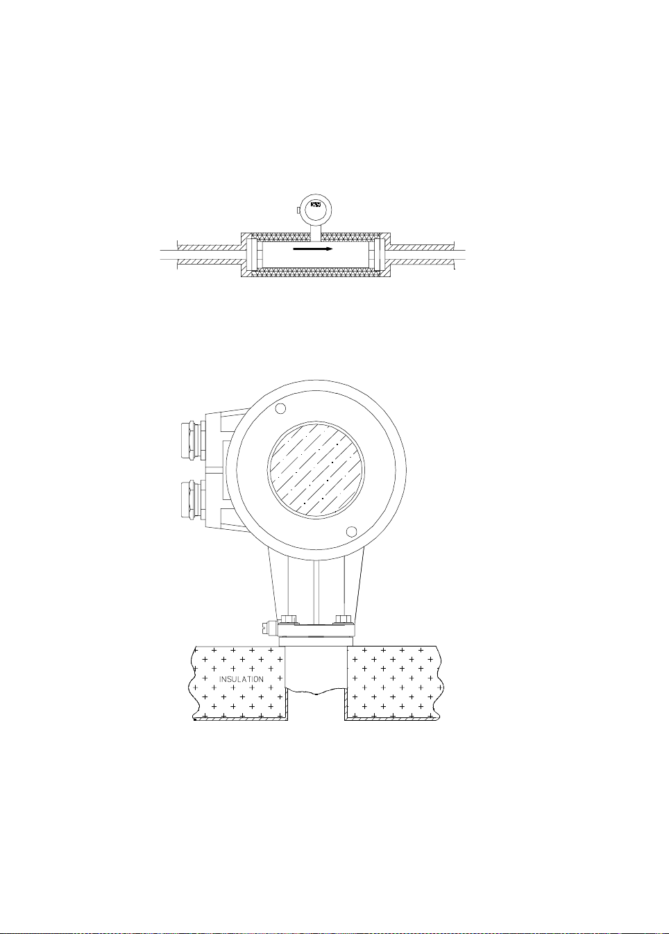
It is recommended that the pipework and insulation material be installed as in figure 10. The
ins ul ati on ca n b e Rubb er, Foam , G las s Fi br e or a ny ot her pro ces s su it abl e mat eri al . It s houl d,
however, be firmly fixed with no components such as straps or covers that can vibrate.
Figure 10
Insulation Principle
11
Page 12
Notes:
1. Insulation Material: Rubber, Foam, Glass Fibre, or any other process suitable material.
2. Insulation must be firmly fixed to the pipework.
If especially desired by the customer, it is permissible to insulate the meter itself. If this is
required, then the following guidelines should be followed.
The insulation must be firmly fixed to the meter with no components such as straps or covers
that can vibrate (figure 11). DO NOT insulate converter (figure 12).
Figure 11
Important No te:
When insulating Ex meters, insulation must not rise above the square plate that connects the
sensor and converter (figure 12).
Figure 12
In addition, any heat tracing used (electrical or fluid) must not exceed 130°C for titanium meters
(optional 150°C). For zirconium meters maximum temperature is 100°C. The Ex temperature
cl asses are also different , see table below.
12
Page 13
Ex Temperature Classes for Insulated/Heated Meters
Process Temperature Temperature Class
65°C T5
100°C T4
130°C T3
Optional 150°C T3-T1
If remote meters are insulated (see figure 13), it is imperative that the insulation does not rise
above the square plate mentioned above and a thermal insulation adapter must be purchased
from Krohne and fitted as shown.
Figure 13
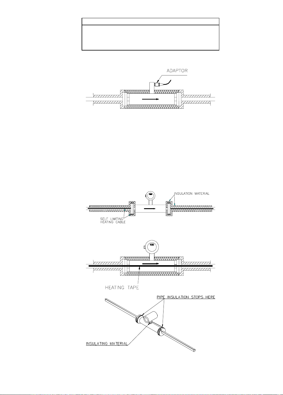
1.3.2 Electrical Trace Heating
The use of electrical heating tape is illustrated in figures 14,15,16 and 17. The use of selflimiting tape is ideal, but other types of electrical heating may be used. Any thermostat should
be fitted to the adjacent pipework, if this is done it should be firmly fixed with no loose wires or
connections that could vibrate. If only pipework and flanges are insulated, two turns of heating
tape should be tightly applied to the flanges and covered in insulation as shown. All heating
tapes should be tightly fixed with no areas that could vibrate. Between the flanges the heating
tape should be secured to the converter neck, but insulated from it (figure 16) or run back to the
first clamp and then in a loop to the opposite clamp (figure 17). Krohne can supply a list of
electrical heating tape suppliers, if required. If the meter case is insulated then heating tape
may be applied tightly under the insulation. It is recommended that the heating tape be applied
axially and continuously taped down (figure 15).
Figure 14
Figure 15
Figure 16
13
Page 14
The converter must not be insulated or heated. For Ex meters refer to ‘important note’ in
‘Insulation’ section above.
In all cases, the installation factor should be monitored and maintained within the normal
levels.
Figure 17
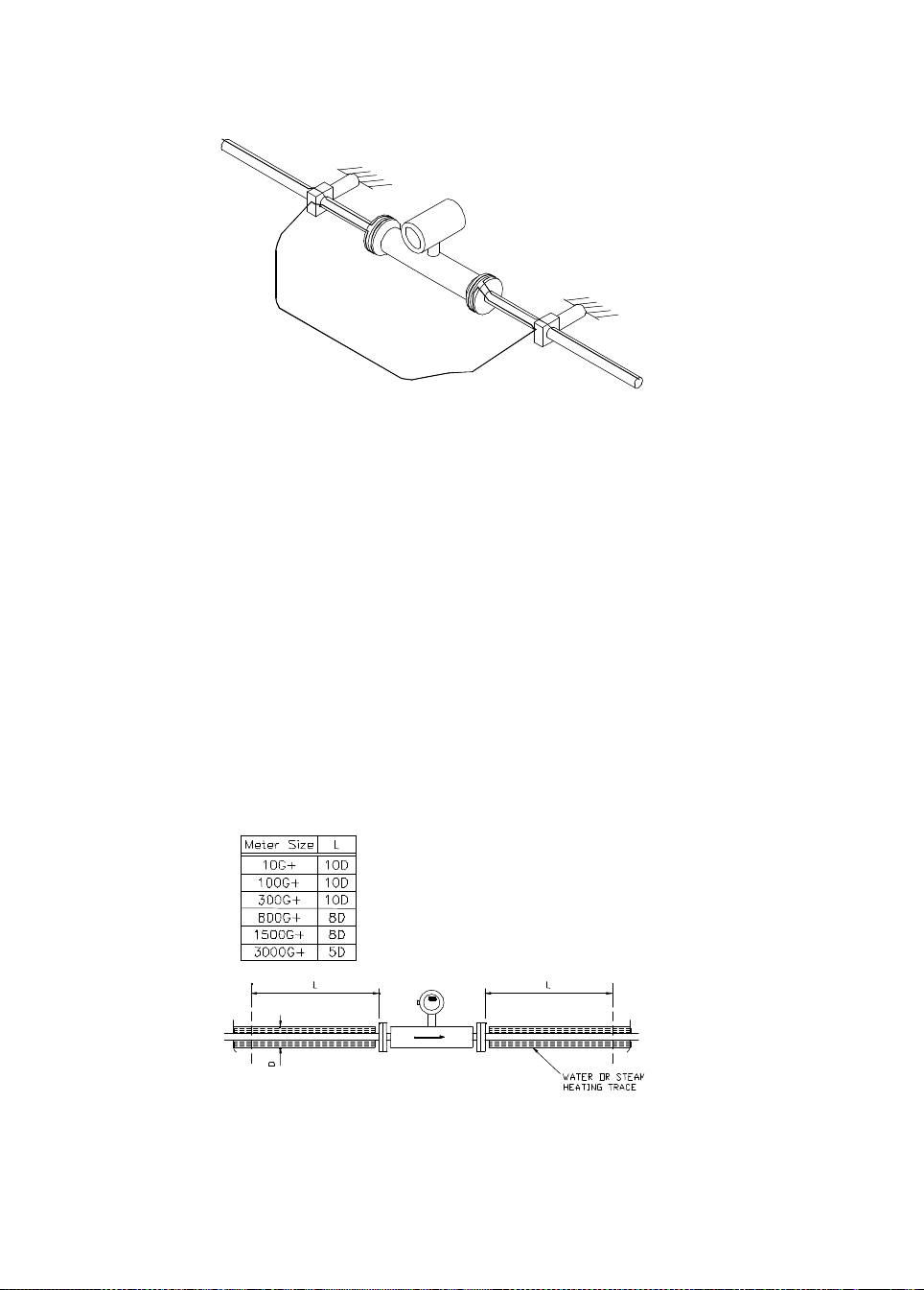
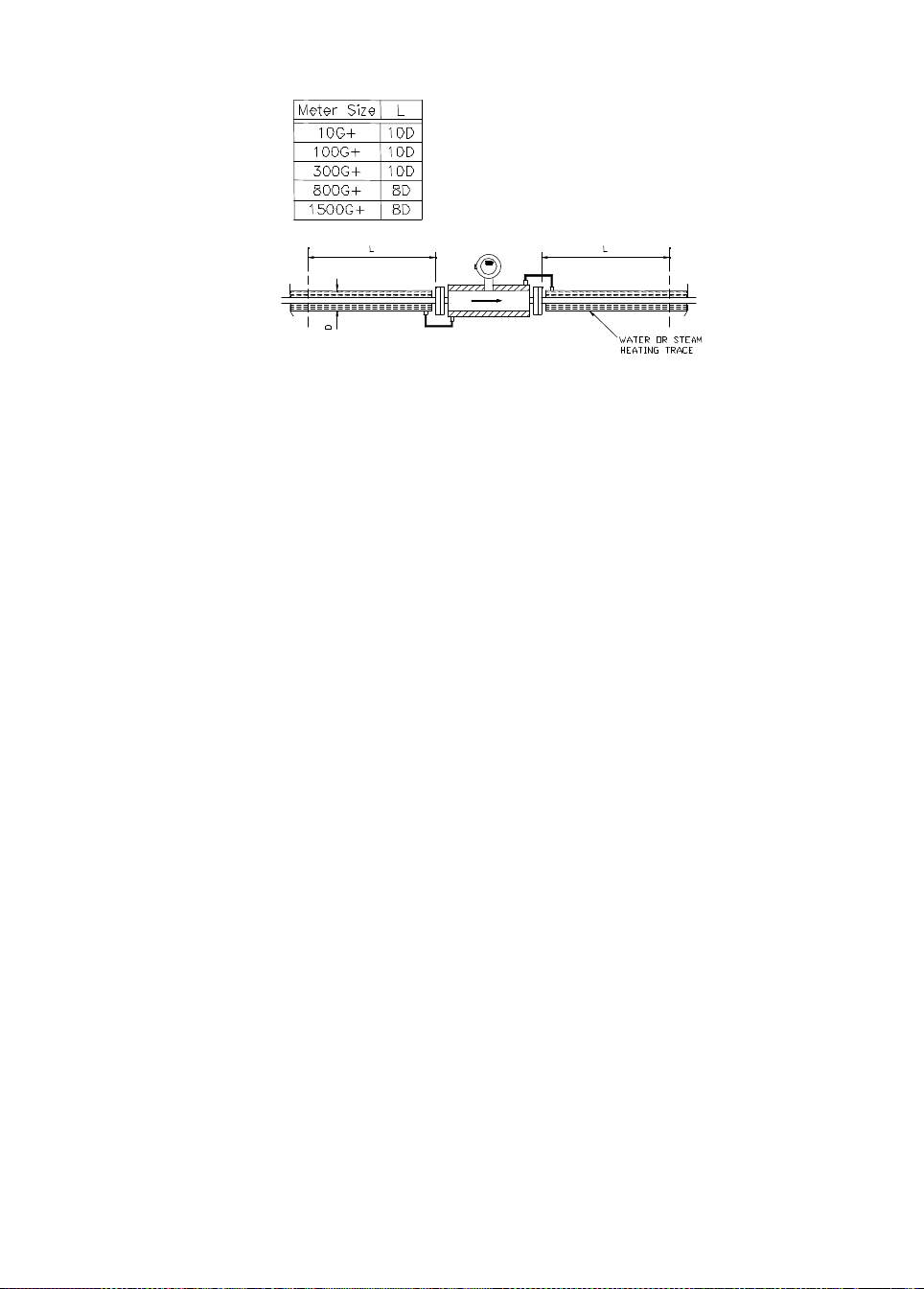
1.3.3 Hot Fluid or Steam Heating
Where pipelines are jacketed with concentric pipes, carrying a hot fluid such as water or steam,
follow the following recommendations.
The jacket should be of as small a diameter as possible and the wall thickness should be as thin
as possible (figure 18).
A radial gap between the process pipe and the inside of the jacket of 5-6mm is suitable.
The minimum clamping distance is increased (figure 18). The first clamp should be moved
further away from the meter.
It i s an advant age t o avoi d proc ess pipewo rk of a large diamet er comp ared to the meter bore.
Krohne can provide further guidelines and dimensions of suitable pipes and jackets.
The jacket must be completely filled with no air pockets present.
Any clamps or supports must be applied at a distance greater than L.
Figure18
14
Page 15
Also availa ble are special jacketed meters as s hown in fi gure 19. These are also Ex app roved .
Remote jacketed meter must be fitted with an insulation adaptor shown in fig. 13.
Figure 19
In all ca s es, the installat io n fa ctor sh ould be moni to red and m aintain ed wit hin normal levels.
1.3.4 Heating Up From Cold
The proceeding insulation and heating instructions also apply in this case, together with the
following notes:
The low thermal coupling between the Titanium tube and the flanges means that maintaining a
G+ Meter at a desired temperature is straight forward as already described, however, heating
from cold an uninsulated meter can be a lengthy process, particularly if the customer’s product
could be damaged by high rates of heat input at the flanges. The areas at each end of the
meter can be heated from 20°C to 60°C in about 2 hours, but the centre of the meter can take 5
hours to reach this temperature particularly if the product has solidified. It is possible to speed
this up if the meter is mounted vertically and a reduction of abou t an hour is possible, if the case
is insulated. If the case is also heated, heating times are further cut.
The above comments assume that there is no flow through the meter. If there is flow through
the meter then the desired temperature can be reached within a few minutes.
Another important fact to note, is that it is rarely necessary to fully melt all the product which has
solidified in the meter, as it has been demonstrated that any ‘plug’ of product can be pushed
through the meter by pumping pressures of less than 1 bar. Any ‘plug’ would be rapidly melted
in the joining pipework. This fact is an important benefit of the single straight tube design and is
not true of bent tube meters, or meters with flow dividers and multiple tubes.
Temperature Note
Most work in this subject has considered product temperature up to 80°C, if higher
temperatures are required by the customer the proceeding guidelines still apply, but heat up
from cold times will be extended.
The G+ Met ers ha ve maximum o perating t emper atures, as foll ows:
Zirconium Tubes 100°C
Titanium Tubes 130°C
Titanium Tubes (to special order) 150°C
15
Page 16
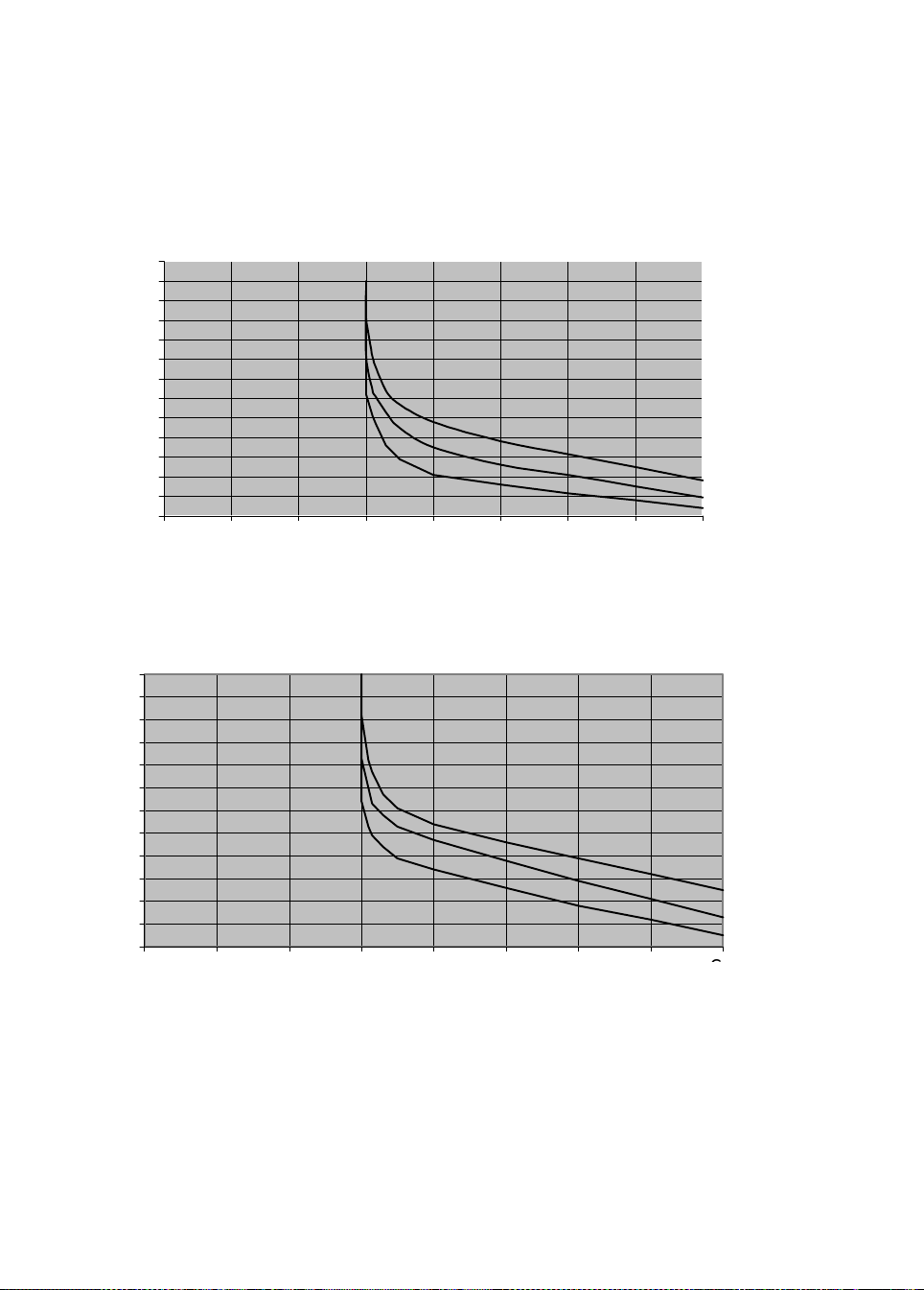
On Titanium tube meters, it is, however, possible to exceed 150°C up to an absolute maximum
of 200°C, for short periods. The time is limited by the initial temperature and final temperature.
To assess the time allowable, refer to figures 11,12 and 13, which cover the 10G+, 100G+ and
300G+ meters. For the 800G+ and 1500G+ refer to Krohne Ltd.
This does not apply to the 3000G+. These meters must not exceed 130°C. Zirconium tube
meters must never exceed 100°C.
ALLOWABLE TIME AT HIGH TEMP .
10 G METER
130
120
110
100
90
80
70
60
50
TIME MIN.
40
30
20
10
0
120 130 140 150 160 170 180 190 200
Initial temp 30 C
Initial temp 70 C
Initial temp 120 C
TEMP. C
ALLOWABLE TIME AT HIGH TEMP.
120
110
100
90
80
70
60
50
TIME MIN.
40
30
20
10
0
120 130 140 150 160 170 180 190 200
100G METER
TEMP. C
Initial temp 30 C
Initial temp 70 C
Initial temp 120
16
Page 17
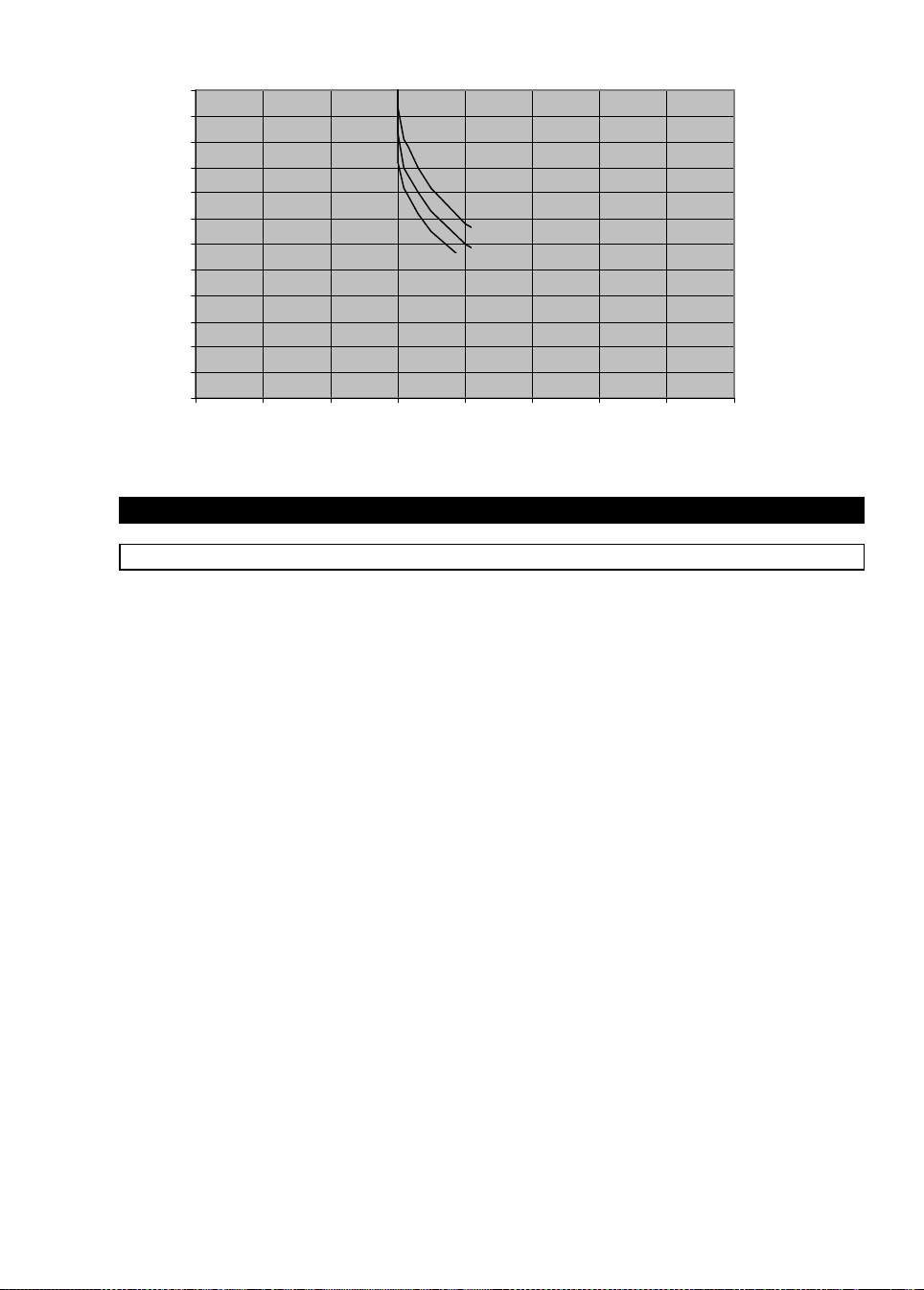
ALLOWABLE TIME AT HIGH TMP.
120
110
100
90
80
70
60
50
TIME MIN.
40
30
20
10
0
120 130 140 150 160 170 180 190 200
2. Electrical installation
2.1 Location and connecting cables
300G/ 800G METER
Initial
Initial
Initial
TEMP. C
Location
Do not expose the compact flow meter to direct sunlight. Install a sunshade if necessary.
Connecting cables
To conform to protection category requirements, observe the following recommendations:
– Fit blanking plug PG 16 and apply sealant to unused cable entries.
– Do not kin k cabl es directly at ca ble entries.
– Provide water drip point (U bend in cable).
– Do not connect rigid conduit to cable entries.
– If c ables are a tight fit, enla r ge in side diameter o f cable gland by removing t he appropriate
ring(s) from the seal.
17
Page 18
2.2 Connection to power
Please ensure that the information about power given on the
data plate corresponds to the locally ava ilable mains voltage.
– Note information given on the instrument data plate (voltage, frequency)!
– Electrical connection in conformity with IEC 364 or equivalent national standard.
Special regulations apply to installation in hazardous areas. Please refer to separate "Ex"
insta llat io n in struction s .
– The PE protective ground conductor must be connected to the separate U-clamp
termin al in t he terminal box of the signal converter.
– Do not cross or loop the cables in the terminal box of the signal converter. Use separate
(PG or NPT) cable glands for power and output cables.
– Ensure that the screw thread of the round cover on the terminal box is well greased at all
times.
NOTE: The grease used must be non-corrosive to aluminium; typically it must be resin- and
acid-free.
– Protect sealing ring from da mage .
5 6 4 4.1 4.2 11 12
N L AC
+ DC
Outputs and
connections
see S ect. 2.3
–
PE
Power and signal connections for MFC 085 K
2.3 Inputs and outputs
The table below shows the input/output connection for the converter. The exact configuration
depends on which optional output modules were fitted in the factory.
Table of input/output connections
Trm.
No.
5 Common (-) Common (-)
6 Current output (+) Curr ent output 1 (+)
4 Control input Control input.
4.1 Pulse output Current output 2 (+)
4.2 Status out put (active) Sta tus ou tput (pas sive)
* The inputs/outputs share a common signal ground that is galvanically isolated from ground
(PE).
Option 1
(Current, pulse, status
output and control input )
Option 2
(2 current,NGI
status ou tp ut )
*
18
Page 19
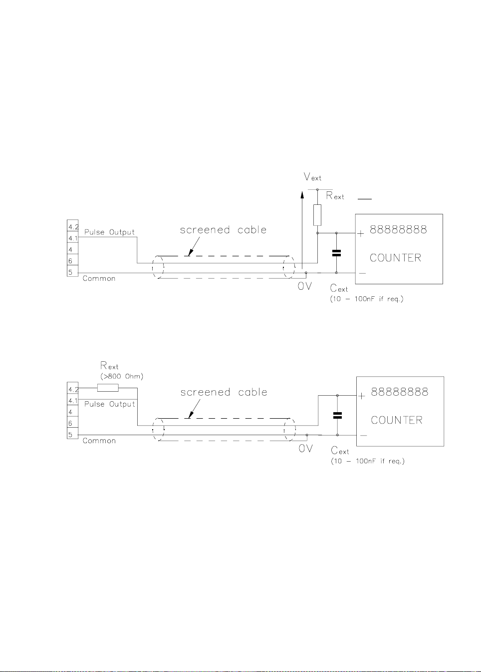
For the standard converter, the pulse output is passive and requires an external voltage
source for operation. In addition, the signal may need protection from external electrical
interference. The use of screened cables and a filter capacitor next to any counter is
recommended. (Fig. a)
It is possible to connect the pulse output without using an external voltage supply. However to
do this the function of the alarm output must be sacrificed. (Fig. b).
If the alarm o utput is used to power the pu lse signa l then the followin g settings must be made
in the menus.
(i) Fct. 3.5.1 ALARM FUNCTION must be set to OFF
(ii) Fct. 3.5.2 ALARM ACTIVE LEVEL must be set to ACTIVE LOW.
(Max. 24 V DC)
V
ext
150 mA)
(
≤
R
ext
Fig. a Pr eferred connections to an external counter with separate power supply
(Example). For correct wiring see table of Input/ output connections
Fig. b Connection without external voltage source (Example). For correct wiring see
table of Input/ output connection
19
Page 20
Additional input/output options
Tr
Opt ion 4*
(Current an d
m.
RS485)
No.
5 Common
(-)
6 Current
output 1 (+)
4 TX/RX TX/RX Control Input Current
4.1 TX/RX TX/RX Pulse
4.2 +5V +5V Pulse
Opt ion 5*
(Current an d
Modbus)
Common
(-)
Current
output 1 (+)
Option 6
(1 Current,
1 Dual
phase pu lse
output an d
control
input)
Common
(-)
Current
output 1 (+)
Output A
Output B
Option C
(2 current,
pulse an d
control
input)
Common
(-)
Current
output (+)
output 2 (+)
Control Input Current
Pulse
Output
Option D
(3 current
and
pulse)
Common
(-)
Current
output 1 (+)
Current
output 2 (+)
output 3 (+)
Pulse output Control Input status output
Option E
(3 current
and
control
input)
Common
(-)
Current
output 1 (+)
Current
output 2 (+)
Current
output 3 (+)
Option F
(3 current
and
status
output)
Common
(-)
Current
output 1 (+)
Current
output 2 (+)
Current
output 3 (+)
(passive)
The p uls e out alarm ou tputs where sel ected are passi ve.
* Refer to separate RS 485 or Modbus manual
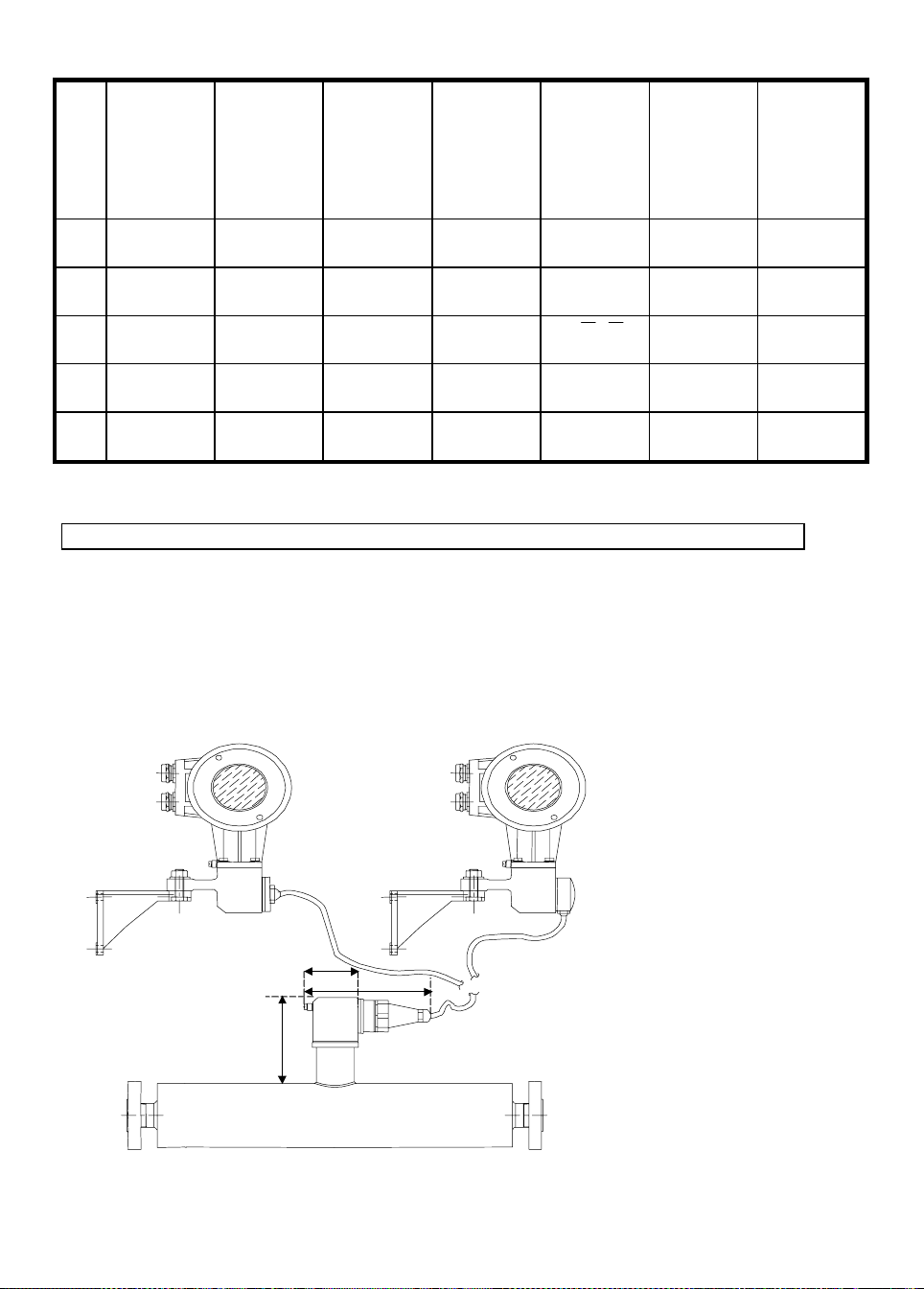
2.4 Connection of remote meters
The G meter can be supplied as remote meter with 5 m cable. Under no circumstances should
the cable be cut shorter or joined to increase its length. The meter is calibrated with this 5m
length. Any changes will influence the performance of the meter.
There are two di fferent conf igurations of remote meter, on the firs t vers ion the cable is fixed at
the converter end and the second has a terminal junction box at the converter end.
50
145
115
20
Page 21
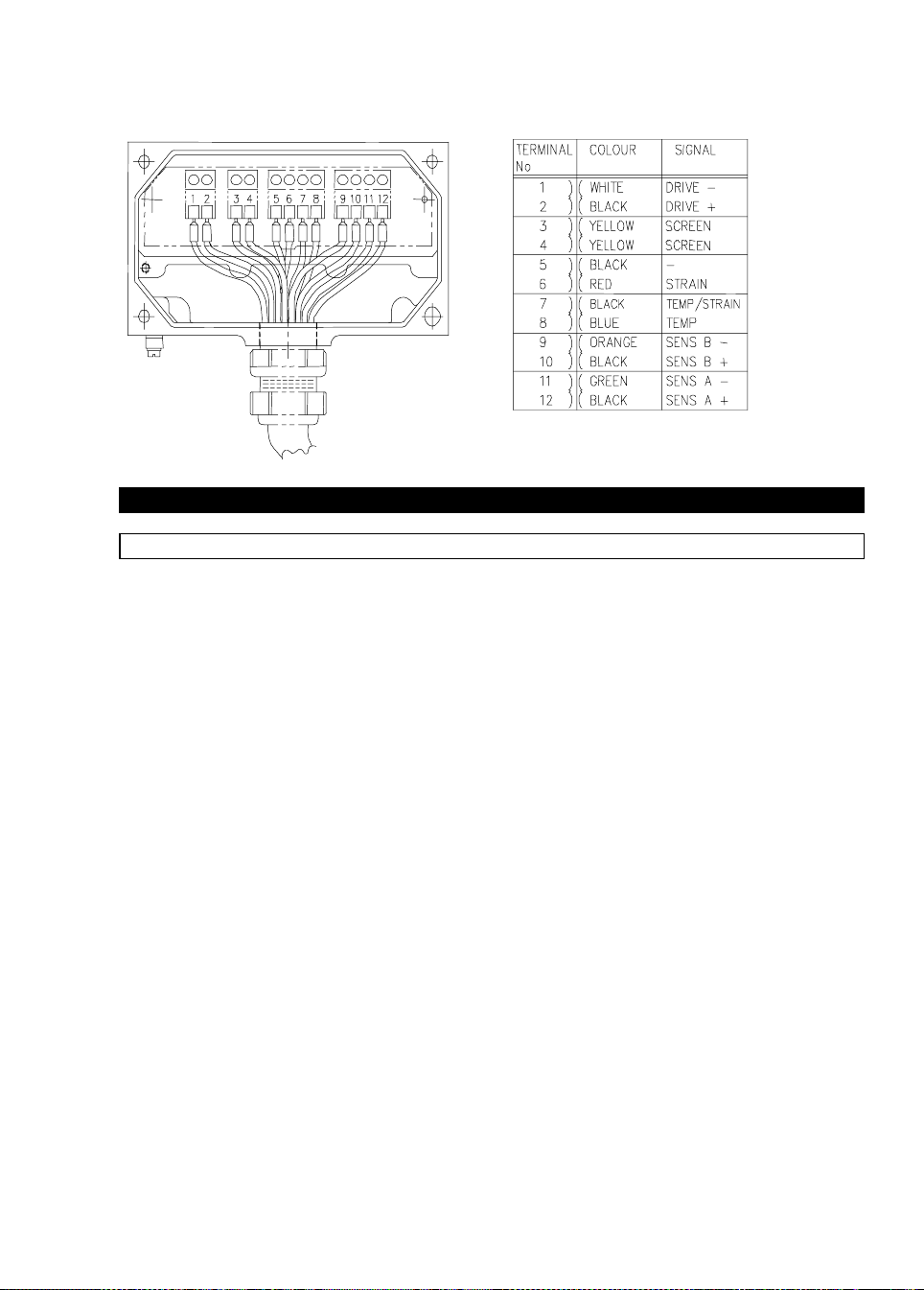
The connection on the transducer end is done for both versions over a special connector. On
the fixed version the connection on the converter side is fixed. The second option uses a
junction box for the connection. Wiring is done according to the following figure. PG 16 or ¾”
NPT adaptor are available with the junction box version to put the cable into flexible conduit.
3. Start-up
3.1 Factory Set Parameters
The mass flow meter leaves the factory ready to be used. All process data has been
program med a ccor ding to the c ustomer order. See factory programming s heet d elivered with
the flow meter.
When no process details were supplied at the time of order, the mass flow meter is programmed
to a standard default set of values and functions.
The current and pulse outputs treat all flows as positive. The actual flow and quantity is thereby
measured independent of the flow direction. The indicator will indicate a ” – ” or ” + ” in front of
the flow rate.
These factory-set settings for current and pulse may cause an error under the following
conditions: When the pump is stopped and a reverse flow is present, which is larger than the
low flow cut-off or when totalizing should be indicated for both flow directions.
To a void these poss ible prob lems:
a) Set fl ow mo de (Fc t . 3.1.8) to either fl ow > 0 or Flow < 0, so that rever se fl ows are igno red.
or
b) Increase Low Flow cut-off (Fct. 3.1.7) so that small reverse flows are ignored.
or
c) Set the alarm outp ut (Fct. 3.5.1) to DIRECTION s o t hat extern al eq uipment c an dif ferentiate
between positive and negative flows.
21
Page 22

3.2 Initial Start-up
• Please check that the power supply corresponds to the information supplied on the data
plate.
• Switch on the power supply.
• On switch-on, the signal converter first carries out a self-test. The following sequence is
displayed:
TEST
10 G GX.XX
Pri mary Head S oftware V ersion
STARTUP
Mass flow will be displayed following a brief settling phase for the primary head.
A minimum warm-up time of 30 minutes is recommended to
ensure stable measurement operation.
• For stable and accurate mass flow results the following should be checked:
a) The quality of the mechanical installation. See Sect. 1.2.2.
b) A good zero point calibration should be done. See Sect. 3.4. Further information
regarding zero point calibration can be found in Sect. 5.
3.3 Installation factor
The extensive self-diagnosis functions of the MFM 4085 also include a so-called installation
factor. This factor indicates whether the flow meter has been correctly installed in the pipeline
and whether the mounting supports have been fitted at defined points. For that reason, the
installation factor must without fail be checked during the initial start-up phase. The installation
factor can be checked by way of the keystroke combination as in Sect. 1.2.3.
If corr ectl y install ed, the val ue of the installation facto r when the pr imar y head is full of water
should be as per table in section 1.2.3. If the figure is higher, the specified accuracy of the flow
meter cannot be guaranteed. Please check the installation again on the basis of the installation
information (Sect. 1.2). If necessary adjust clamping with the meter displaying the installation
factor to obtain optimum performance.
3.4 Zero point adjustment
After installation adjust the zero point. To do this, the primary head must be completely filled
with the liquid product without gas or air inclusions. This is best obtained by allowing the
liquid product to flow through the primary head for approx. 2 minutes at a throughput rate of
greater than 50% of rated flow. Subseque ntly ensure tha t flow co mes to a complete stop in the
primary head (see fig 10, Section 1.2) for setting the zero without interruption to product flow,
use a bypass set-up as shown in fig. 11 (Section 1.2). For best results the zero adjustment
should be performed with the front cover in place. To activate the calibration, use the bar
magnet provided to operate the magnetic sensors on the display.
22
Page 23

Now initiate zero adjustment by way of the following keystroke combination:
Start from measuring mode
Key Display
line 1 line 2
→ Fct. (1).0 OPERATOR
2x→ Fc t. 1. 1.(1) Z ERO SET
→ (MEASURE.VAL.)
↵ CALIB. (NO)
↑ CALI B. ( YES)
↵ X.X PERCENT
ACCEPT (YES)
↵ Fct. 1.1.(1) ZERO SET
3x↵ ACCEPT (YES)
↵ Display
Under certain conditions, it may not be possible to adjust the zero point:
– If the medium is in motion. Shut-off valves not tightly closed.
– If there are gaseous inclusions in the primary head. Flush the primary head and repeat the
calibration.
– If resonant oscillations of the piping are interfering with the primary head. Check the
clamping of the in strument.
– If there ar e active warning(s ) in the status m es sage list. (See section 4.6)
In such cases, the zero point adjustment procedure is automatically aborted and the following
message is displayed for a short time:
ZERO.ERROR
Then the converter returns to the start of the function 1.1.1:
Fct. 1.1.1 ZERO SET
Further information on zero point adjustment is given in Section 5.
The CORIMASS MFM 4085 is ready to operate after zero has been adjusted.
All parameters have been fa ctory-set in keepin g with the data s pecified in your ord er. Detailed
information for further setting of the signal converter will be found in Part B of the operating
instructions.
23
Page 24
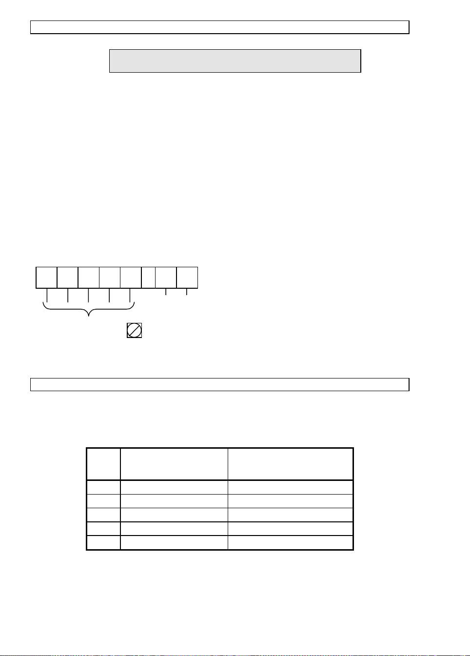
3.5 Programming the converter with a bar magnet
• The converte r can be programme d by mean s of the magnet ic se nsors moun te d on the
faceplate without removing the front lid.
• To do this, a bar magnet (standard supply) is used to activate the sensors by holding the
magnet close to the glass window of the housing lid.
• These sensors then duplicate the functions of the push buttons.
24
Page 25
Part B MFC 085 Signal Converter
4. Operation of the Signal converter
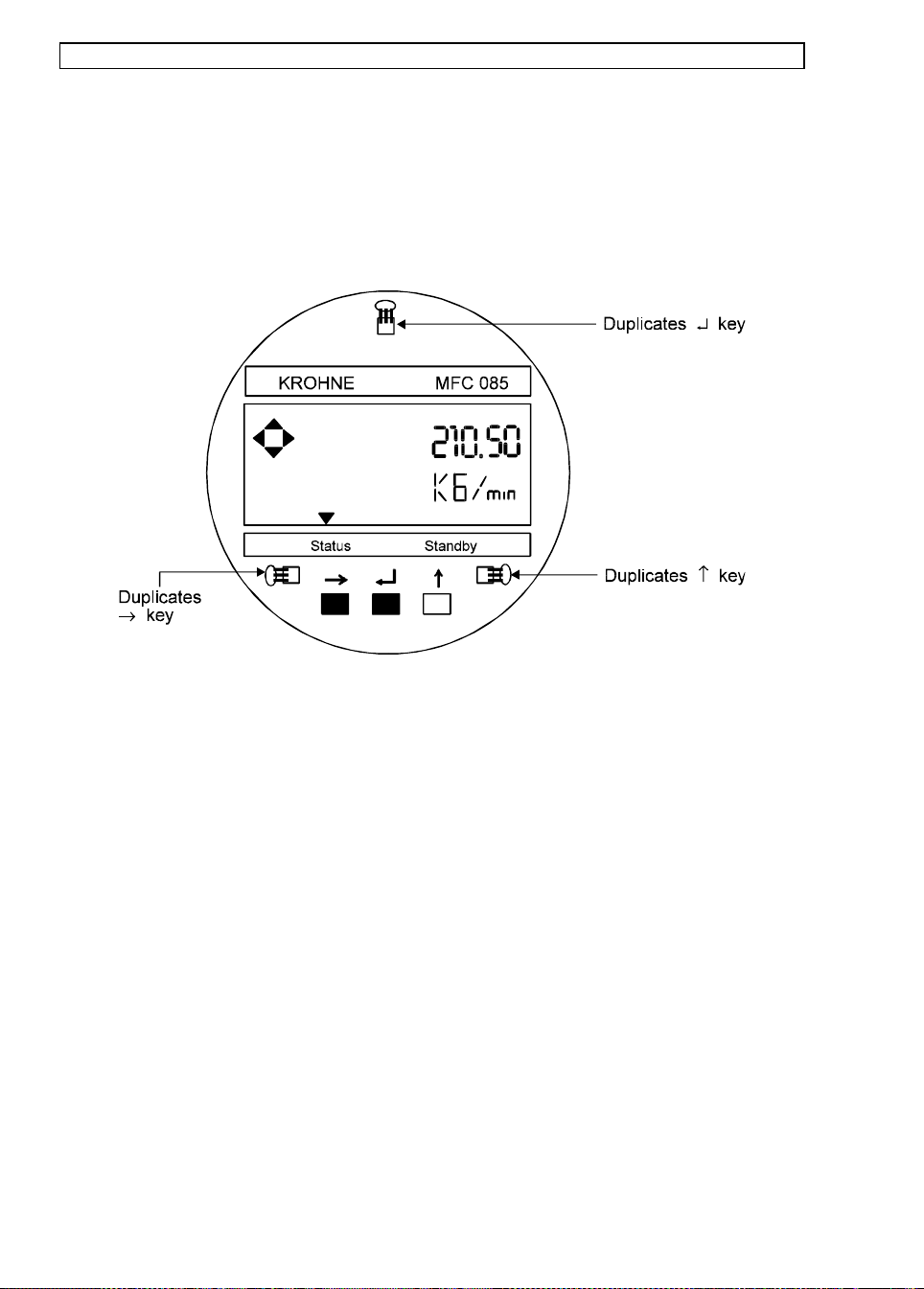
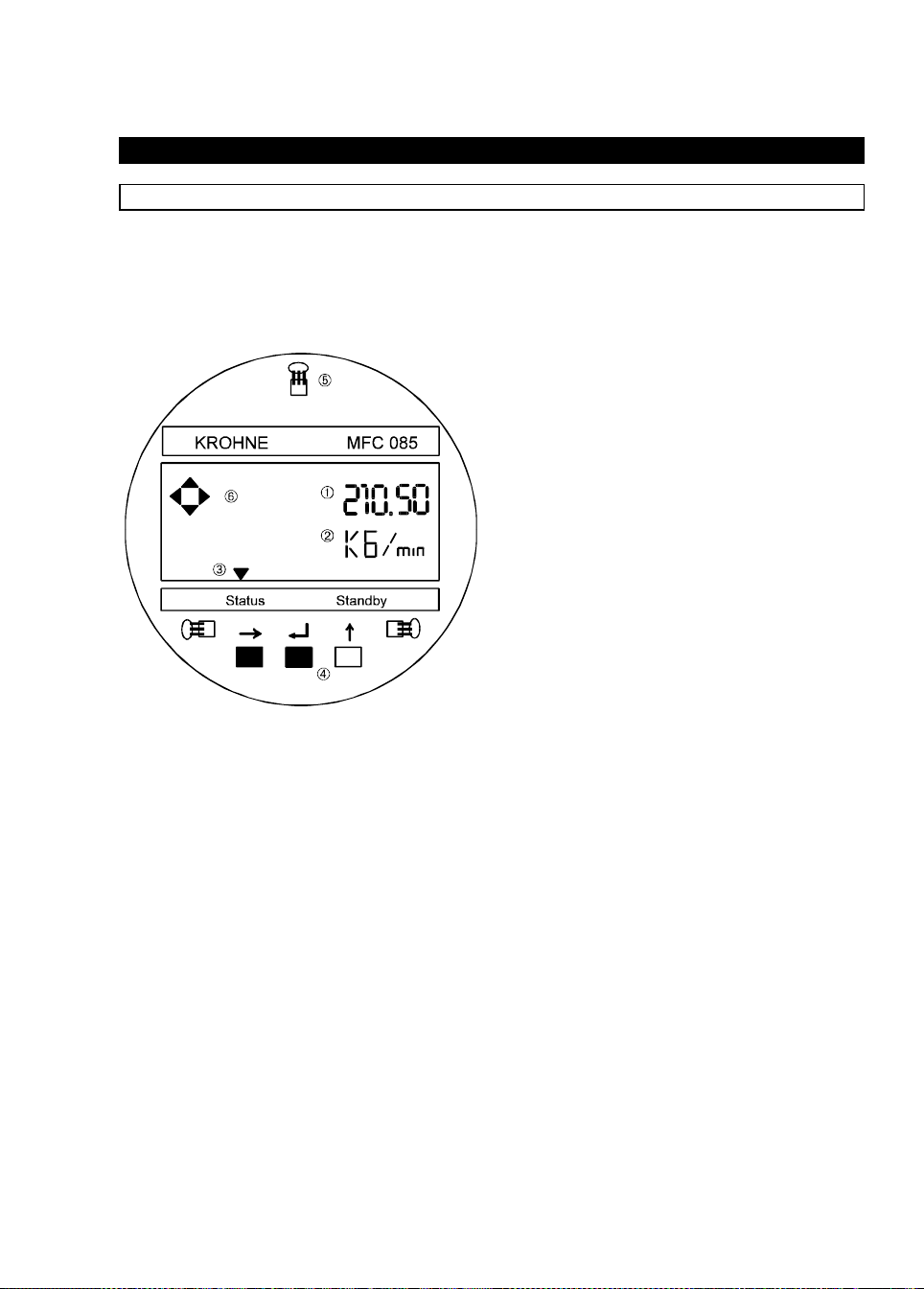
4.1 Operating and check elements
The o perating elements are accessibl e after removing the c over of the elect ronics section usi ng
the special wrench. The converter is also programmable with magnetic sensors and a bar
magnet without removing the covers of the electronic housing.
Caution:
The operator control concept consists of three levels (horizontal). See next page.
Setting level:
Parameter check level: Fct. 4.0 PARAM.ERROR
Reset/acknowledge
level (Qui t):
Do not damage the screw thread and the gasket, never allow dirt to accumulate,
and make sure they are well greased at all times.
① Display 1st (top) line
② Display 2nd (middle line
③ Display 3rd (bottom line:
arrows (τ) to identify the state
of the signal converter
Status
–
–
④ Keys for operator control of the
signal converter.
⑤ Magnetic sensors to set the
converter by means of a
handheld bar magnet without
opening the housing. Function
of sensors same as keys ℘.
⑥ Compass field, signals
actuation of a key.
This level is divided into three main menus:
Fct. 1.0 OPERATION
important parameters and functions of Menu 3 (install) to allow
rapid changes to be made during the measurement mode.
Fct. 2.0 TEST
(displays, outputs, measuring range).
Fct. 3.0 INSTALL
parameters and functions can be set in this menu.
After exiting from the ”Sett ing l evel”, th e sign al convert er ch ecks
new data for plausibility. If an error is detected, the signal
converter indicates PARAM.ERROR in Fct. 4.0. In this menu, all
functions can be scanned and those changed that are not
”plausible”.
This menu has two tasks and is selected via Entry Code 2
( ↵ ↑ → )
1) Resetting of totalizer, provided that resetting is enabled under
Fct. 3.8.5 ENABL.RESET, input YES.
2) Status message and acknowledgement (Quit) messages that
have occurred since the last acknowledgement are indicated in
a list. After elimination of the cause(s) and acknowledgement,
these mes sages are deleted from th e list .
: Test menu for checking the signal converter
: This menu contains only the most
: All flow measurement- and flowmeter-spe cific
: This leve l is not se lectable.
message indicator
Standby
mode
25
Page 26
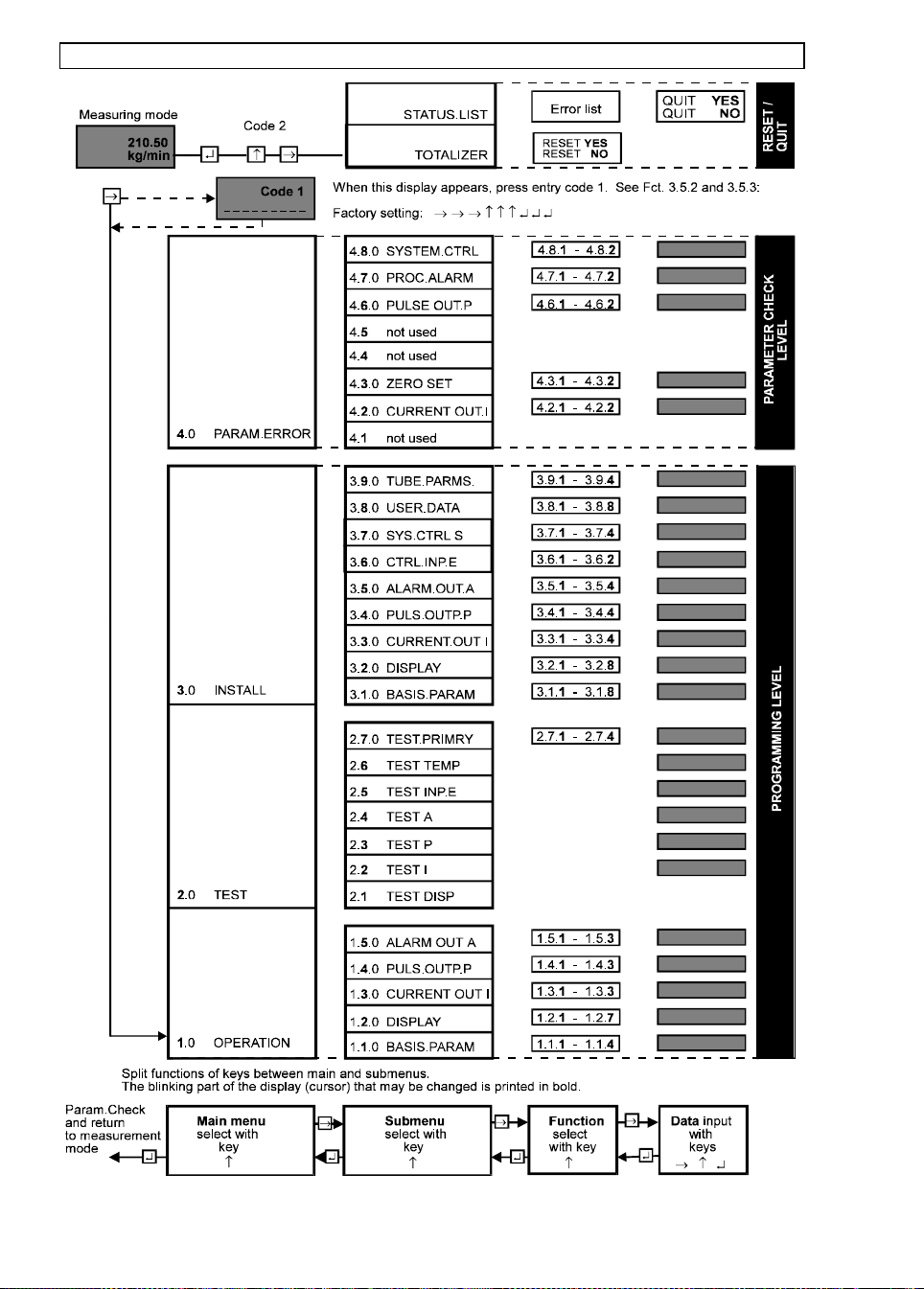
4.2 Krohne Operating Concept
26
Page 27

4.3 Key functions
Function of the keys
Cursor
The location of the cursor on the display is indicated by flashing characters. This
cou ld be a sing le digit when entering number; numeric sig n ( + or -) ; meas ure-ment
units (g,kg,t etc.); or any other text field. Throughout this manual the location of the
cursor, in programming examples, will be indicated by parentheses ( ) around the
flashing characters.
↑ Select or Up Key. This key changes the field/digit under the cursor.
- Digit: Increase value by 1 for each key press. (0 follows 9).
- Dec. pt. Move decimal point. 0000(.)0000 changes to 00000(.)000
- Menu Increase menu number by 1. i.e. Fct. 1.(1).0 changes to
Fct. 1.( 2 ).0
When the menu number reaches its maximum the next ↑ changes the
number to 1. i.e. Fct 1.(5).0 changes to Fct 1.(1).0
- Text Change text field. i.e. ”YES” to ”NO” or ”g” to ”kg” to ”t” etc.
- Sign Toggle ”+” to ”-”
→
Cursor or Right Key. This key moves the cursor onto the next field to be edited.
(usually the next on the right).
- Number Move cursor from 12(3).50 to 123(.)50 to 123.(5)0
- Text Move to next field. i.e. (kg)/min to kg/(min)
- Menu Move to next menu column: i.e. from Fct 1.(2).0 to Fct. 1.2.(1)
or
if the cursor is already in the rightmost column: invoke that menu
function. i.e. from Fct. 1.2. (1) press → to edit MASS FLOW format.
↵ Accept or Enter Key.
-Within a
Accept changes (if any) and exit the function.
function
-Menu Move cursor to the next column on the left.
i.e. from Fct. 1.2.(1) back to Fct. 1.(2).0
If the cursor is already in the leftmost column then ↵ exits the menus.
See next box: ”To terminate” .
Note:
If numerical values are set that are outside the permissible input range, the display shows the
min. or max. . accept ab l e val ue. After pr ess i ng the ↵ the numb er m ay b e c orr ec ted.
27
Page 28

4.3.1 How to enter programming mode
To start:
Display Comments
→ Pres s Fct . 1.0
If this appears, see next box: ”Function of the keys ” .
Operation
or
CodE 1
---------
If this appears on the display, set the 9-keystroke Entry
CodE 1 .
Factory setting: → → → ↵ ↵ ↵ ↑ ↑ ↑
1st- 8thplace
(key)
9th place
(key)
CodE 1
∗∗∗∗∗∗∗∗-
Fct. 1.0
Operation
CodE 1
(9 alpha
Each keystroke acknowledged by " ∗ " in display.
If this appears, see box: ”Function of the keys ” below.
A wrong Entry CodE 1 was keyed in. Press any key and set
the correct 9-keystroke
characters)
4.3.2 How to terminate Programming mode
To terminate:
Press ↵ 1-3
times
↵ + 12.345
Fct (1).0
OPERATOR
kg/min
Press ↵ 1-3 times until the cursor is under the extreme
left menu column. (Fct. 1.0 , 2.0 or 3.0)
If no changes have been made to the system’s configuration return directly to the measurement mode.
or
(ACCEPT YES) Changes have been detected. Press ↵ to accept these
changes.
or
↑
(ACCEPT NO)
Press ↵ to reject changes and return directly to
measurement mode.
or
↑
(GO BACK)
Press ↵ to return to the menus, Fct. 1.(0) to make
further changes
↵ PARAM.CHECK Assuming ACCEPT YES was selected,
the system now checks the new setting for errors.
After 1-2 sec. + 12.345
No errors detected. Return to measurement mode.
kg/min
or
Fct. (4).0
PARAM.ERROR
Errors were detected. The sub-menus of 4.0 will guide
the operator to those functions where problems have
been identified.
28
Page 29
Examples
The cursor (flashing part of display) has a grey background in the following examples:
To start programming
Measurement mode Programming mode
13.571
→
Fct. 1. 0
m3 / h r OPERAT I ON
PLEASE NOTE: When ”yes” is set under Fct. 3.8.2 ENTRY CODE, the following will
appear in the display after pressing the → key:
CodE 1 - - - - - - - - -.
The 9-stroke entry code must now be entered.
Factory setting: → → → ↵ ↵ ↵ ↑ ↑ ↑.
Each keystroke is acknowledged by an ” ∗ ” in the display.
To terminate programming
Press ↵ key repeatedly until one of the following menus are displayed:
Fct. 1.0 OPERATION, Fct. 2.0 TEST or Fct. 3.0 INSTALL
Press ↵ key
Fct. 3. 0
INSTALL. A C C E P
↵
T.
Y E S
To accept the new parameters
Press ↵ to confirm.
”PARAM.CHECK” will appear in th e displa y.
The measuring mode will continue after a few
seconds with the new parameters, when no
errors are detected.
When an error is detec ted the di spla y will
indicate ”Fct. 4. 0 PARAM.ERROR”. The error
parameters can be called up in this menu and
corrected.
New parameters not to be accepted
When the new param eters are no t to be
accepted, the following keystrokes should be
executed: Press ↑ key. The display will
show ”ACCEPT NO”. When the ↵ key is
then pressed, the instrument will return to the
measurement mode using the old parameters.
29
Page 30
To change numeric values
Increase numeric value
210. 5 0
↑
210.6 0
kg/mi n kg/mi n
To move the cursor (flashing digit)
To move to the right
210. 6 0
→
210.6 0
kg/mi n kg/mi n
To move the decimal point
To move to the right
21. 060
↑
210. 6 0
kg/mi n kg/mi n
To change the text
Select next text
↑
M A S S F L O W D E N S I T Y
To change the units
Numeric v alues autom aticall y c onv er t ed
Select new unit
0.21060
↑
210.60
g /min k g /min
Alternative time unit
210. 60
→
k g /min kg/m i n
To change from numeric values back to text
Alternative engineering units
210. 60
→
kg/mi n k g /min
Return to function display
10.3
↵
Sec TIMECONST.
30
210.60
210.60
F c t. 1. 1. 3
Page 31

4.4 Table of programmable functions
Fct. No. Text Description and settings
1.0 OPERATION Main menu 1.0 Operation
1.1.0 BASIS.PARAM Submenu 1.1.0 Base data
1.1.1 ZERO SET Zero adjustment . See Fc t. 3. 1.1
1.1.2 L.F. CUTOFF Low flow cutoff. See Fct. 3.1.2
1.1.3 TIME CONST. Signal converter time constant. See Fct. 3.1.3
1.1.4 STANDBY Switching between measuring operation
and standby. See Fct. 3.1.4
1.2.0 DISPLAY Submenu 1.2.0 Display
1.2.1 CYCL.DISP Switching between steady display and cyclic display
1.2.2 STATUS MSG Sel ects which status messages should be displayed
1.2.3 MASS FLOW Unit for mass flow. See Fct. 3.2.3
1.2.4 MASS TOTAL Unit for mass total. See Fct. 3.2. 4
1.2.5 DENSITY Unit for density. see Fct. 3.2.5
1.2.6 TEMPERAT Unit for temperature. see Fct. 3. 2.6
1.2.7 VOLUME.FLOW Unit for volume flow. See Fct. 3.2.7
1.2.8 VOLUME.TOTAL Unit for volume total. See Fct. 3.2.8
1.2.9 CONC.MEAS Parameters for concentration mea su rement. See
separate concentration meas urement instruction manual
1.2.10 CONC.MEAS See 1.2.9
1.2.11 CONC.MEAS See 1.2.9
1.3.0 CUR.OUTP. I Submenu 1.3.0 Current output I.
1.3.1 FUNCTIO N I Function current output I. see Fct. 3.3.1
1.3.2 MIN.VALUE* Minimum range for current output I see Fct. 3. 3.3
1.3.3 MAX.VALUE
*
Maximu m ra n ge for current ou tp ut I see Fct. 3.3.4
1.4.0 PULS.OUTP. P Submen u 1.4.0 Pulse, frequency output P. see Fct. 3.4.0
1.4.1 FUNCTIO N P Select. Parameter to be totalized
1.4.2 PULSE/MASS * Select. Pulse per unit
1.4.3 PULSE WIDTH * Select pulse width in milliseconds
1.5.0 ALARM.OUT.A Submenu 1.5.0 Process alarm output A. see Fc t. 3.5.0
1.5.1 FUNCTIO N A Se lect ala r m functio n. See Fc t. 3.5.1
1.5.2 ACTIV.LEVEL Select. active high or low. See Fct. 3.5.2
*
Exact disp l ay d epends on s elec ted function. See su b- menu 3.3.0
31
Page 32

Fct. No. Text Description and settings
2.0 TEST Main Menu 2.0. Test functions
2.1 TEST DISP. Carry ou t disp l ay te st.
Start with the key → (Duration of test approx. 30 sec.).
Stop test at any time with the ↵ key.
2.2 TEST I Test current output I
* SURE (NO). Use the ↑ key to select YES, then press ↵.
* 0 mA wil l be output f rom t he converter. U se th e ↑ key
to select test currents from the list below.
0 mA, 2 mA, 4 mA, 10 mA, 16mA, 20 mA, 22 mA.
To exit test mode, press the ↵ key at any time.
2.3 TEST P Test frequency output P
* SURE (NO). Use the ↑ key to select YES ,then
press ↵ key.
2.3.1 FREQUENCY * LEVEL LOW 0 volt DC level will be output from the
converter.
Use the ↑ key to select test signals from the list below.
* LEVEL HIGH (+ V volts dc)
* 1 Hz * 100 Hz
* 10 Hz *1000 Hz
2.3.2 TEST PULSE * Test Pulse
Use the ↑ key to select desired pulse width from the list
below:
∗ 0.4 mSec ∗ 100.0 mSec
∗ 1.0 mSec ∗ 500.0 mSec
∗ 10.0 mSec
Then press ↵. The system now sends pulses of the
required width. To stop the test press ↵ twice.
2.4 TEST A Test alarm output
* SURE (NO). Use the ↑ key to select YES, then
press ↵
* LEVEL LOW. 0 Volts is output on the alarm terminal.
Press the ↑ key to switch output to:
* LEVEL HIGH . +24V dc is output on the alarm terminal.
To exit test mode, press the ↵ key at any time.
2.5 TEST INP.E Test control input
The a ctu al in put level, HI or LO , and t he selected
functi ons are displa yed see Fct. 3.6.1
End test by pressing the ↵ key.
2.6 TEST TEMP. Test temperature and strain gauge
Start with the → key . The temperature in °C is display ed.
Use the ↑ key to dis play the t emperature in °F. Us e t he
↑ key again to display strain. End the test by pressing
↵ key
2.7.0 TEST.PRIMRY. Sub menu 2.7.0 Test primary head values.
2.7.1 SENSOR A Monitor the amplitudes of sensor A and B
2.7.2 SENSOR B as percentage of their max. value. (80% is ideal)
Start test with the → key. End the test with the ↵ key.
2.7.3 FREQUENCY Monitor the primary head frequency.
Start test with the → key. End the test with the ↵ key.
2.7.4 INSTAL.FACT. Monitor the primary head's drive level.
Start test with the → key. End test with the ↵ key.
32
Page 33

Fct. No. Text Description and settings
3.0 INSTALL. Main menu 3.0 Installation
3.1.0 BASIS.PARAM Submenu 3.1.0 Base data
3.1.1 ZERO SET Zero adjustment .
Use the ↑ key to select between MEASURE.VAL.
and SET VALUE then press the ↵ key.
* MEAS.VALUE (ensure "ZERO" flow in the pipeline)
1) Select: CALIB.YES or NO
2) If YES: Calibration (approx. 20 sec. duration)
Display: Actual flow rate as percent of the
maximum rated flow for the primary head. (Q
100%
3) Select: ACCEPT YES or NO
* SET.VALUE Direct input of a zero flow offset.
Units: As sel ected by Fct. 1.2.1 or 3.2.1
3.1.2 L.F. CUTOFF Low flow cutoff
Value: 0 to 10 percent of nominal flow
3.1.3 TIME CONST. Time constant for output of measured values
Range 0.5 ... 20 sec. (Option: 0,2 ... 20 sec.)
3.1.4 STANDBY Use the key ↑ to switch between three modes
of operation, then press ↵:
* MEASURE
* STANDBY (tube vibrating, Mass Flow set to zero)
* STOP (tube drive stopped)
Note: It is not possible to switch directly
from STOP to STANDBY.
3.1.5 PRIMRY.TYPE Type of the primary head **
Using t he ↑ key select the primary head type
that is connected to the converter:
* 10 G * 800 G
*100 G *1500 G
*300 G *3000 G
Then press → key to select material field, then ↑ key to
select:
* T * T+ * Z * Z+ as per the data plate
3.1.6 CF5 Primary head constant. **
Displays the primary head constant as stamped
on the primary head’s data plate. (Password protected)
3.1.7 FLOW DIR. Define direction of flow.
Select either FORWARD or BACKWARD
3.1.8 FLOW MODE Define whether bi-directional or uni-directional
flow is expected. Select either:
* FLOW > 0 (Ignore negative flows)
* FLOW < 0 (Ignore positive flows)
* FLOW +/- (Allow positive and negative flows)
)
** These menus are protected by the Code 4 password, see Fct. 3.8.8
33
Page 34

Fct. No. Text Description and settings
3.2.0 DISPLAY Su bmenu 3.2 .0 DISPLAY
3.2.1 CYCL. DISP. Cyclic display required?
Setting NO or YES. If YES is selected then in
measurement mode the display will switch from Mass
Flow to Density to Total to Temperature every 4 seconds.
3.2.2 STATUS MSG. Which status messages to be displayed ?
* NO MESSAGE (= no warning messages in main
display, warning system ignores status of outputs)
* PRIMRY.HEAD (= light warning messages in the
main display, warning system ignores status of
outputs)
* OUTPUT (= output saturation/alarm status
messages in the main display)
* ALL MSG. (= all warning messages in the main
display. System responds to output status)
3.2.3 MASS FLOW Units and format for mass flow display
* g, kg, t, oz, lb per s, min, h, d
* Number of digits after the d ecimal point selectabl e.
3.2.4 MASS TOTAL Units and format for totaliser
* g, kg, t, oz, lb
* Number of digits after the decimal point selectable.
3.2.5 DENSITY Units and format for density
* g, kg, t, per cm3, dm3, litre, m3 or
oz, lb per in3 ,ft3 , USgal, gallon or SG (Specific
Gravity relative to water at 20°C)
* Number of digits after the decimal point selectable.
3.2.6 TEMPERAT. Units for temperature
*°C or °F
* Format fixed at 1 decimal place
3.2.7 VOLUME.FLOW Units and format for volume flow
* Select OFF (no volume flow d ispl ay) or
*cm3, dm3, litre, m3 , in3 ,ft3 , USgal, or gallon
per
* s, min, hr, day
* Number of digits after the decimal point selectable.
3.2.8 VOL.TOTAL Units and format for totalizer
cm3, dm3, liter , m3, inch3, ft3, US gal, gallon.
3.2.9 to 3.2.11 Concentration menu when installed.
Please refer to separate Concentration instruction manual
34
Page 35

Fct. No. Text Description and settings
3.3.0 CUR.OUTP. I Submenu Current output I
For systems with 2 or more current outputs see Sect. 4.7
3.3.1 FUNCTIO N I Function current output I
* OFF (O/P current = 0 mA)
* MASS FLOW (Mass flow in range MIN [Fct. 3.3.3] to
MAX [Fct. 3.3.4] output as current in range [Fct 3.3.2]
0/4-20mA)
* DE NSIT Y (Density in range MIN [Fct. 3.3.3] to MAX
[Fct. 3.3.4] output as current in range [Fct 3.3.2]
0/4-20 mA)
* TEMPERATUR (Temperature in range MIN [Fct. 3.3.3]
to MAX [Fct. 3.3.4] output as current in range
[Fct 3.3.2] 0/4-20 mA)
* VOL.FLOW (Volume flow in range MIN [Fct. 3.3.3]
to MAX [Fct. 3.3.4] output as current in range
[Fct 3.3.2] 0/4-20 mA)
SOLUTE.FLOW Concentration measurement
CONC. BY MASS functions available if installed
CONC.BY (see sep. instruction manual).
* DIRECTION (Negative flow gives current of 0/4 mA,
positive flow gives current of 20 mA)
3.3.2 RANGE I Range for current output I: Select from the following
by pressing ↑ key and then ↵ key
*0-20 mA
*4-20 mA
* 0-20/22 mA (O/P = 22 mA when error detected)
* 2/4-20 mA (O/P = 2 mA when error detected)
* 3.5/4-2 0 m A (O/P = 3.5 mA when error detec ted)
3.3.3 MIN.VALUE Value of measured quantity as set by Fct. 3.3.1
or MIN. FLOW, that corresponds to the minimum output current
or MIN. DENSITY (0 or 4 mA as set by 3.3.2)
or MIN. TEMP.
or MIN V.FLOW
or MIN.CONC. Menu not available if Function 3.3.1 is set to OFF or
DIRECTION
3.3.4 MAX.VALUE Value of measured quantity as set by Fct. 3.3.1
or MAX. FLOW, that corresponds to an output current of 20 mA
or MAX. DENSITY,
or MAX TEMP
or MAX V.FLOW
or MAX.CONC Menu not available if Function 3.3.1 is set to OFF or
DIRECTION
35
Page 36

Fct. No. Text Description and settings
3.4.0 PULS.OUTP. P Submenu 3.4.0 Frequency output P
3.4.1 FUNCTIO N P Function frequency output P
* OFF (Output = 0V DC)
* MASS FLOW (Frequency output 0 to MAX Freq. Hz =
Mass Flow in range: MIN. FLOW to MAX FLOW as set
in Fct. 3.4.3 and 3.4.4)
* MASS TOTAL(1 pulse = fixed mass as set in Fct 3.4.2)
* DENSITY (Frequency output 0 to MAX Freq. Hz =
Density in range: MIN.DENSITY to MAX.DENSITY as
set in Fct. 3.4.3 an d 3.4.4)
* TEMPERAT. (Frequency output 0 to MAX Freq. Hz =
Temperature in range: MIN. TEMP to MAX. TEMP as
set in Fct. 3.4.3 an d 3.4.4)
* VOLUME.FLOW(Frequency output 0 to MAX Freq. Hz
= Volume flow in range: MIN. V.FLOW to MAX.
V.FLOW as set in Fct. 3.4.3 and Fct. 3.4.4)
* VOL.TOTAL(1 pulse = fixed volume as set in Fct 3.4.2)
SOLUTE.FLOW
SOLUTE.FLOW Concentration parameters if
CONC.BY.MASS option installed. See separate
CON:BY:VOLUME instruction manual.
* DIRECTION (Negative flow gives output of 0 volts DC ,
Positive flow gives output of +V volts DC)
3.4.2 PULSE/MASS M ass per pulse value for function TOTAL MASS
or PULSE/VOL. Volume per pulse value for function VOL. TOTAL
or PULSE/TIME Maximum frequency value for functions MASS FLOW,
DENSITY, TEMPERATUR and VOLUME.FLOW or
CONC.OPTIONS. Not accessible for functions OFF and
DIRECTION.
3.4.3 MIN.VALUE Value of measured quantity that corresponds to
or MIN. FLOW, 0 Hz output
or MIN. DENSITY,
or MIN. TEMP.
or MIN. V.FLOW
or CONC.OPTIONS
or PULSE.WIDTH For functions MASS TOTAL, VOL.TOTAL OR
SOL.TOTAL. Not accessible for functions OFF and
DIRECTIONS
3.4.4 Full Scale Value of measured quantity that corresponds to
or MAX. FLOW, Max. Frequency
or MAX. DENSITY
or MAX TEMP.
or MAX V.FLOW
or CO NC.OPTIONS Not accessible for functions OFF, DIRECTION, TOTAL
MASS TOTAL, or VOL. TOTAL
36
Page 37

Fct. No. Text Description and settings
}
3.5.0 ALARM.OUT.A Sub menu 3.5.0 Process alarm output
3.5.1 FUNCTIO N A Function for alarm output P
* OFF (Output goes to its inactive state)
* MASS FLOW (Alarm active if mass flow goes outside
limits as set in Fcts. 3.5.3 and 3.5.4)
* MASS TOTAL (Alarm active if totaliser goes outside
limits as set in Fcts. 3.5.3 and 3.5.4)
* DENSITY (Alarm active if density goes outside limits
as set in Fcts. 3.5.3 and 3.5.4)
* TEMPERAT. (Alarm active if temperature goes outside
limits as set in Fcts. 3.5.3 and 3.5.4)
* VOLUME.FLOW (Alarm active if volume flow go
outside limits as set in Fcts. 3.5.3 and 3.5.4)
* VOL.TOTAL (Alarm active ...
Solute flow Concentration option
Conc. by mass if installed. See separate
Conc. by volume instruction manual
* I 1.SAT (Alarm active if value output on current output
exceeds the range as set in Fct. 3.3.3 and 3.3.4)
* P 1.SAT (Alarm active if value output on pulse output
is either: > 1 . 3 x Max Limit as set in Fct 3 .3.4 or
< Min Limit as set in Fct 3.3.3
* AN Y O/P .SAT ( Alarm active if value output on eith er
curren t or pulse output exceeds t he selected ran ges)
* SEVERE ERR. (Output active if a severe error is
detected)
* ALL MSG. (Output active if any warnings occur)
* DIRECTION (Output active for positive flows, inactive
for negative flows)
3.5.2 ACTIV.LEVEL Select the desired voltage level for the active state
* ACTIVE.HIGH (24 V dc)
* ACTIVE LOW (0 V dc)
3.5.3 MIN. LIMIT Minimum allowable value for functions
TOTAL MASS, MASS FLOW, DENSITY,
TEMPERATUR and VOLUME.FLOW
Units: depend on function but will correspond
to those set in Fcts. 3.2.1 to 3.2.5
or Not accessible for all other functions
3.5.4 MAX. LIMIT. Maximum allowable value for functions
MASS TOTAL, MASS FLOW, DENSITY,
TEMPERATUR and VOLUME.FLOW
Units: depend on function but will correspond
to those set in Fcts. 3.2.1 and 3.2.5
or Not accessible for all other functions
37
Page 38

Fct. No. Text Description and settings
3.6.0 CTRL.INP.E Submenu 3. 6.0 C ontr ol input
3.6.1 FUNCTIO N E Function of the control input
* OFF (control input inactive)
* STANDBY (When active converter switches to
STANDBY)
* ZERO SET (Zero calibration triggered on the transition
from inactive to active on the control input)
* RESET TOTAL (Totaliser reset to zero on the transition
from inactive to active on the control input)
* CLEAR. MSG. (Status warnings cleared on the
transition from inactive to active on the control input)
3.6.2 ACTIV.LEVEL Set the desired voltage level for the input to be active
* ACTIVE LOW (0 to 2 V)
* ACTIVE.HIGH (4 to 24 V)
3.7.0 SYS.CTRL S Submenu 3.7.0 System control
3.7.1 FUNCTIO N S Function for system control
* OFF (System control inactive)
* FLOW = OFF (Mass flow readings forced to zero,
total iser frozen)
* FLOW = 0/RST. (Mass flow readings forced to zero,
totaliser frozen while active but reset to zero
as condition becomes inactive. Not available with
Custody Transfer Protection)
* OUTPUTS OFF (Forces all outputs to their OFF states)
3.7.2 REFERENCE Condition for triggering the above function
* DENSITY (Function is triggered if density goes outside
Max or Min limits as set in Fcts 3.7.3 and 3.7.4)
* TEMPERATUR (Function is triggered if temperature
goes outside Max or Min limits as set in Fct 3.7.3 and
3.7.4) Function not available with Custody Transfer
Protection.
3.7.3 MIN. LIMIT. Minimum allowable value of temperature or density
selected in Fct. 3.7.2
Units: depend on function but will correspond
to those set in Fct. 3.2.1 and 3.2.5
Function not available with Custody Transfer Protection.
3.7.4 MAX. LIMIT. Maximum allowab le value of temperatur e or density
selected in Fct. 3.7.2
Units: depend on function but will correspond
to those set in Fct. 3.2.1 and 3.2.5
Function not available with Custody Transfer Protection.
38
Page 39

Fct. No. Text Description and settings
3.8.0 USER DATA Submen u 3.8.0 User dat a
3.8.1 LANGUAGE Language for display text
* GB/USA (= English)
* F (= French)
*D (= German)
3.8.2 ENTRY.CODE1 Entry code for accessing menus required?
* NO (Entry to menus with the → key only)
* YES(Entry with → key and 9-keystroke code see
Fct 3.8.3)
3.8.3 CODE 1 Set Code 1 (Fct. 3.8.2 must be set to YES otherwise this
function is not available)
* Factory setting: → → → ↵ ↵ ↵ ↑ ↑ ↑
* If a different code is required:
press any 9-keystroke combination and then press the
same key combination again. Each keystroke is
acknowledged by "*". CODE WRONG (incorrect entry)
appears if 1st and 2nd entries are not the same. Press
↵ then → keys and repeat the procedure.
3.8.4 LOCATION Tag name setting (measuring point number)
Required only for flow meters using the MIC 500 Hand
Held Communicator (HHC), connected to current output)..
Factory setting: ”MFC 085”
Characters assignable to each place:
A...Z / 0...9 / + / - / * / = / // ( > = blank character)
3.8.5 ENABL. RESET Allow total iser rese t from the
RESET/ACKNOWLEDGE
menu or with Control.Input E
Select : NO/YES
3.8.6 CSTDY CODE 3 Custody transfer required?
The function is protected by the CODE E password. After
pressing the → key enter a 9-keystroke password. If in-
correct, 9 characters are displayed which can be decoded
in the factory, otherwise select:
* NO (No protection)
* YES (Custody Transfer Protection requir ed)
3.8.7 CODE 3 CodE E setting (9 characters). (If custody transfer
is active then this function is unavailable)
* Factory setting: ↵ → ↑ ↵ ↑ → ↵ → ↑
* If a different code is required, press any 9-keystroke
combination and then pre ss the same key combination
again. Each keystroke is acknowledged by "*".
CODE WRONG appears if 1st and 2nd entries are not the
same. Press ↵ then → keys and repeat the procedure.
3.8.8 PARAM.CODE 4 Extra code ↵ ↑ to allow subsequent access to
Menus: Fct . 3.1.5
Fct. 3.1.6
Fct. 3.9.3
Fct. 3.9.4
39
Page 40

Fct. No. Text Description and settings
3.9.0 TUBE PARAMS Submenu 3.9.0 primary head specific parameters
Pas sword pro tected, s ee Fct . 3.8. 8
3.9.1 CF1 Density coefficient 1
Input the value stamped on the primary head’s data plate
or perform on site calibration as described in Sect. 5.12.
3.9.2 CF2 Density coefficient 2
Input the value stamped on the primary head’s data plate
or perform on site calibration as described in Sect. 5.12.
3.9.3 CF3 * Reference strain
Displays the value stamped on the primary head’s data
plate.
3.9.4 CF4 * Reference temperature
Displays the value stamped on the primary head’s data
plate.
3.9.5 CF5 *Primary head constant
Displays the value stamped on the primary head’s data
plate.
3.9.6 DSS CF6 Density strain slope
Displa ys the valu e whi ch is menti oned on the c al. Sheet
3.9.7 DTS CF 7 Density temperature sl ope
Displa ys the valu e whi ch is menti oned on the c al. Sheet
3.9.8 FSS CF8 Slope strain
Displa ys the valu e whi ch is menti oned on the c al. Sheet
3.9.9 FTS CF9 Slope temperature
Displa ys the valu e whi ch is menti oned on the c al. Sheet
3.9.10 D.REF.HIGH Density adjustment, High Point
3.9.11 D.REF.LOW Density adjustment, Low Point
3.10.0 CONC.MEAS Concentration measurement option when installed
3.10.1 SOLUTE R20 See separate Concentration instruction manual
3.10.2 SOLUTE K1 See separate Concentration instruction manual
3.10.3 SOLUTE K2 See separate Concentration instruction manual
3.10.4 LIQUID See separate Concentration instruction manual
3.10.5 LIQUIDR20 See separate Concentration instruction manual
3.10.6 LIQUID K1 See separate Concentration instruction manual
3.10.7 LIQUID K2 See separate Concentration instruction manual
3.11.0 SERIAL I/O RS485 or Modbus option, if installed
3.11.1 PROTOCOL See separate RS485 or Modbus instruction manual
3.11.2 ADDRESS See separate RS485 or Modbus instruction manual
3.11.3 BAUDRATE As per 3.11.1
* Only accessible if allowed through password in Fct. 3.8.8.
40
Page 41

Fct. No. Text Description and settings
4.0 PARAM.ERROR Main Men u 4.0 Parameter error
4.1 Not Used
4.2.0 CUR.OUTP.I Range settings incorrect
LOW SCALE ≥ FULL SCALE
4.2.1 LOW SCALE Low scale range for current output I see Fct. 3.3.3
4.2.2 FULL SCALE Full scale range for current output I see Fct. 3 .3.4
4.3.0 ZERO Zero calibration incorrect.
The measured zero offset must be less than ±10 %
of the primary head’s full scale flow rating.
4.3.1 ZERO SET Zero calibration see Fct. 3.1.7
4.3.2 PRIMRY.TYPE Type of primary head see Fct. 3.1.5
4.4 Not Used
4.5 Not Used
4.6.0 PULS.OUTP. P Range setting incorrect
LOW SCALE ≥ FULL SCALE
4.6.1 LOW SCALE Low scale range for pulse output see Fct. 3.4.3
4.6.2 FULL SCALE Full scale range for pulse output see Fct. 3.4.4
4.7.0 PROC. ALARM Minimum and maximum limits incorrec t
MIN.LI MIT > 96 % of MAX.LIMI T
4.7.1 MIN.LIMIT Minimum limit for range checking see Fct. 3. 5.3
4.7.2 MAX.LIMIT Maximum limit for range checking see Fct . 3.5.4
4.8.0 SYS.CTRL.S Minimum and maximum limits incorrec t
MIN.LI MIT > 96 % of MAX.LIMI T
4.8.1 MIN. LIMIT Minimum limit for condition checking see Fct . 3.7.3
4.8.2 MAX. LIMIT Maximum limit for condition checking see Fct . 3.7.4
4.5 Reset / Quit Menu - Totalizer reset and status indication acknowledgement
Totalizer reset
Button Display Description
10.36
Measurement mode
kg
↵ CodE 2
Enter access Code 2 for reset/quit menu: ↑ →
––
↑ → RESET.TOTAL Totalizer reset menu
Only appears if ”yes” programmed in Fct. 3.8.5. Reset
enable No or Yes. If ”no” is programmed ”status light”
only appears. See next section.
→ RESET.YES If the reset function is enabled RESET YES will be
shown, press ↵ to execute th e func tio n.
To c ancel the r eset operation pres s ↑ to get RESET NO
and then press ↵
If the res et function is dis abled by menus Fct. 3. 8.5 or
3.8.6 then BLOCKED is displayed. Press ↵ to continue
↵↵ 0.00
kg
Assuming RESET YES was selected the totalisers will
now be cleared.
41
Page 42

View status message(s) and quit
Button Display Description
0.36
kg/min
∇
↵ CodeE 2
Measurement mode
The p resen ce of the ∇ marker above Status on the
display indicates the presence of warning messages in
the status list.
Enter access code for reset/quit menu: ↑ →
– –
∇
↑→ RESET.TOTAL
Totalizer reset menu.
∇
↑ STATUS.LIST
View/Quit Status message menu
∇
→ ≡ 1 Err ≡
MASS FLOW
∇
This display shows that there is just 1 warning in the list,
in this case MASS FLOW. The ≡ symbols indicate that
this is a new error and not one that has been previously
acknowledged. Use either the ↑ or → keys to view other
messages in the list. Otherwise press ↵ to exit.
→ ≡ 1 Err ≡
QUIT YES
∇
At the end of the message list the QUIT YES prompt is
shown. Selecting YES will clear if possible messages in
the list.
To c ancel the op eration press ↑ to get QUIT NO and
then press ↵
↵ STATUS.LIST Assuming the conditions that caused the message have
passed (i.e. mass flow is back within the meter’s range)
then th e Stat us marker , ∇ will disappear.
↵ 0.36
kg/min
Assuming RESET YES was selected, the totalisers will
now be cleared.
42
Page 43

4.6 Status messages
ERROR
MESSAGES
SAMP LING Sever e P LL out of range
SENSOR A Severe Sensor A voltage signal less than 5% of desired value
SENSOR B Severe Sensor B voltage signal less than 5% of desired value
RATIO A/B Severe O ne sensor signal much larger than the other
EEPROM FATAL Unable to save data in EEPROM. Hardware fault
SYSTEM FATAL I n dic ates soft ware error, will alway s occur with
WATCHDOG Severe Reset due to SYSTEM error or temporary power supply
NVRA M Severe NVRAM ch eck sum error, previous da ta lost
DC A Severe max. DC voltage part of sensor A is larger than 20% of ADC
DC B Severe max. DC voltage part of sensor B is larger than 20% of ADC
NVRAM FULL Li ght NVRAM has exceeded its specified number of write
MASS FLOW Light Mass flow rate > 2 × nominal flow *
ZERO ERROR Light Mass flow rate at zero adjust is larger than > 20% of
TEMPERATUR Light Temperature > outside operating range
STRAIN Light St r ain out of operating range
I.SAT Output Current output saturated **
FREQ.SAT Output Frequency output saturated **
ALARM.OUT. A Outp ut P roc ess alarm l imit chec k exceeded **
ROM DEF Light EEPROM check sum error, defaults loaded from ROM
TOTAL O/F Light Cust ody transfer only. Mass total has overflowed the
TEMP.CUST Light Custody transfer only. Operating temperature has drifted
POWER.FAIL Light Custody transfer only. There has been an interruption of
TYPE COMMENT
WATCHDOG
drop-off
cycles
nominal (100%) flow rate *
display, i.e. it has gone from 99999999 → 00000000
by more than ±30°C from the zer o calibration temperature
power to the converter.
* Actual mass flow rate is too big or manual zero offset PUTIN.VAL in Fct. 1.1.1 was
programmed incorrectly .
** Change output range to avoid saturation.
43
Page 44

4.7 Menu variations for systems with other output options
Fct. No OPTION 1 OPTION 2 OPTION 4 OPTION 5 OPTION 6 OPTION C OPTION D OPTION E OPTION F
Fct. 1.3 CUR.OUTP.I CUR.OUTP.I* CUR.OUTP.I CUR.OUTP.I CUR.OUTP.I CUR.OUTP.I* CUR.OUTP.I* CUR.OUTP.I* CUR.OUTP.I*
Fct. 1.4 PULS.OUT.P BLOCKED BLOCKED BLOCKED PULS.OUT.P PULS.OUT.P PULS.OUT.P BLOCKED BLOCKED
Fct. 1.5 STATUS.OUT.A STATUS.OUT.A BLOCKED BLOCKED BLOCKED BLOCKED BLOCKED BLOCKED STATUS.OUT.A
Fct. 2.2 TEST I TEST I* TE ST I TE ST I TES T I TEST I* TE ST I* TEST I* TEST I*
Fct. 2.3 TEST P BLOCKED BLOCKED BLOCKED TEST P TEST P TEST P BLOCKED BLOCKED
Fct. 2.4 TEST A TEST A BLOCKED BLOCKED BLOCKED BLOCKED BLOCKED BLOCKED TEST A
Fct. 2.5 TEST.INP.E TEST.INP.E BLOCKED BLOCKED BLOCKED BLOCKED BLOCKED TEST.INP.E BLOCKED
Fct. 3.3 CUR.OUTP.I CUR.OUTP.I* CUR.OUTP.I CUR.OUTP.I CUR.OUTP.I CUR.OUTP.I* CUR.OUTP.I* CUR.OUTP.I* CUR.OUTP.I*
Fct. 3.4 PULS.OUTP.P BLOCKED BLOCKED BLOCKED PULS.OUTP.P PULS.OUTP.P PULS.OUTP.P BLOCKED BLOCKED
Fct. 3.5 STATUS.OUT.A STATUS.OUT.A BLOCKED BLOCKED BLOCKED BLOCKED BLOCKED BLOCKED STATUS.OUT.A
Fct. 3.6 CTRL.INP.E CTRL.INP.E BLOCKED BLOCKED BLOCKED CRTL.INP.E BLOCKED CTRL.INP.E BLOCKED
Fct. 4.2 CUR.OUTP.I CUR.OUTP.I* CUR.OUTP.I CUR.OUTP.I CUR.OUTP.I CUR.OUTP.I* CUR.OUTP.I* CUR.OUTP.I* CUR.OUTP.I*
Fct. 4.6 PULS.OUTP.P N/A N/A N/A PULS.OUTP.P PULS.OUTP.P PULS.OUTP.P N/A N/A
Fct. 4.7 STATUS.OUT.A STATUS.OUT.A N/A N/A N/A N/A N/A N/A STATUS.OUT.A
∗
These menus access two or more current outputs.
Press → and a flashing ”1” appears.
i.e. Fct . 1.3.0
CUR.OUTP.I
1
USE THE ↑ TO SELECT THE REQUIRED OUTPUT NUMBER THEN PRESS ↵ TO SELECT.
Page 45

5. Functions
5 Description of Functions
5.1 Zero point adjustment
When operating the system for the first time, it is necessary to set the zero point of the
instrument.
Once the zero point has been adjusted, the installation should not undergo any further
modifications in order to maintain the quality of the measurement. This means that after system
changes (such as the piping or changing the calibration factor), it is advisable to re-adjust the
zero-point.
To a chi eve a suc ces sf ul zer o c ali bra ti on th e pr im ary h ead s houl d be c ompl et ely f ull of pr oc ess
fluid at normal operating pressures and temperatures. Ideally there should be no air inclusions
in the fluid, particularly for horizontal installations, so it is recommended that the primary head
be flushed with the process fluid at a high flow rate (>50%), for 2 minutes, prior to starting the
adjustment. After flushing, flow in the primary head must be brought back to zero by tightly
closing appropriate valves.
The zero off-set can either be measured automatically or entered manually using the display
keys. If an automatic adjustment is to be made then the operator should trigger this, with the
front cover still in place, using the bar magnet provided to operate the magnetic sensors on the
display. This is to ensure that the zero adjustment is carried out with the mechanical installation
exactly the same as for normal operation.
Begin from the measuring mode.
Key Di splay
line 1 line 2
→ 9-key stroke entry code
(if enabled)
Fct. (1).0 OPERATOR
↑ Fct. (2).0 TEST
↑ Fct. (3).0 INSTALL
→ Fct. 3.( 1) BASE DATA
→ F ct. 3.1.(1) Z ERO SET
→ (MEAS.VALUE)
NOTE:
The brackets around parts of the above text indicates the cursor position, these characters will
be flashing on the display. Flashing values can now be changed with the ↑ key. Pressing the →
key moves the cursor to the next ”field” which then starts to flash.
45
Page 46

The operator can now choose either A) Automatic (recommended) or B) manual adjustment.
A) Automatic adjustment :
key Display
line 1 line 2
↵ CALIB. ( NO)
↑ CALI B. ( YES)
↵ X.X PERCENT*
↵ ACCEPT (YES)
4x↵ Return to measuring mode
* Display of actual flow rate % of maximum
value, for a period of 20 seconds.
B) Manual adjustment :
Key Display
line 1 line 2
↑ SET.VALUE
↵ (0).000 kg/min
Input zero value in the
sequ ence : dimension, sign ,
numeric value.
(see section 5.2).
↵
4x↵ Return to measuring mode.
In al l the fol lowin g exampl es, a shor t notat ion i s used f or the setti ng of th e sign al conv erter.
Pushing a key several times is indicated by the number of times without the intermediate display
messages. Only the final display output is listed. If programming is possible in the different
menus 1.0 or 3.0 the only change is in the function number (e.g. for zero adjustment 1.1.1.
instead of 3.1.1.), th e inp uts fo r the programmi ng of the fu ncti ons ar e the s ame.
Under certain conditions, it may not be possible to adjust the zero point, for instance when :
– The medium is i n motion, because t he shut-of f val ves et c. are not functioning properly.
– There are still gaseous inclusions in the primary head because it was flushed insufficiently.
– Resonant vibration of the piping interferes with the primary head because of poor clamping.
In such cases the zero point adjustm ent will not be accept ed. If the zero adj ustm ent was started
by the binary input, the converter will show the message :
ZERO.ERROR
This will appear in th e display fo r a sho rt tim e after the a djustm ent. The convert er also r eports
the ZERO.ERROR in the status list.
If t he zero c alib ratio n was st arted f rom the m enus t hen Par amet er Erro r 4.3 will be di splay ed
when the operator tries to accept the new values.
46
Page 47

Under certain circumstances, when the media consists of unevenly mixed components, it might
be difficult to adjust the zero point. In such a case, the zero point adjustment procedure must be
carried out under special conditions :
– Media which tend to vaporise or degas should be kept under higher pressure.
– Two-phase media consisting of a separable solid component (slurry): In such a case it
might be advisable to fill the primary head with the carrier medium only.
– Other two-phase media .
If it is not possible to separate the solid or gaseous components, the operator can fill the
measuring system with a substitute liquid (e.g. with water).
5.2 Low Flow Cutoff (Fct. 1.1.2 an d 3.1.2)
If the FLOW MODE (Fct. 3.1.8) is set to FLOW +/- then at zero flow small signal fluctuations
will average out to nothing and the totaliser will remain fixed. However, if "one-way flow" is
selected, this avera ging process will not work and the totaliser readi ng will increase sl owly with
time. To prevent this the Low Flow Cutoff should be set.
The Low Flow Cutoff is entered as a percentage of the rated flow of the primary head. The
cutoff may be set in the range of 0.0 to 10.0% in steps of 0.1%.
Thus, for a 10G instrument with a low flow cutoff of 0.2%, any flows less than 0.02 kg/min are
taken as 0 kg/min.
To set the Low Flow Cutoff to 1% :
Key. Display
line 1 line 2
→→→ Fct. 1.1.(1) ZERO SET
↑ Fct. 1.1.(2) L .F.CUTO FF
→ (0)0.0 PERCENT
→↑ (1).0 PERCENT
↵ Fc t. 1. 1.2 L.F. C UTOFF
4x↵
5.3 Time constant
Measurements taken from the primary head require filtering in order to give stable readings in
the presence of fluctuating flows. The degree of filtering also affects how quickly the reading
responds to rapid changes in flow.
SHORT TIME CONSTANT:
FAST RESPONSE
FLUCTUATING READING
LONG TIME CONSTANT:
SLOW RESPONSE
STABLE READING
The figure below shows the typical response of the system for varying Time Constants and a
sharp change in flow.
47
Page 48

To set the Time Constant :
Begin from measuring mode.
Key Display
line 1 line 2
→→→ Fct . 1.1.(1) ZERO SET
↑↑ Fct. 1. 1.(3) TIME. CONST.
→ (0)4.0 TIME C. S.
↵ Fct. 1.1.(3) TIME .CON ST
4x↵
Edit the time constant in
seconds in range 0.5 to 20.
This filtering only applies to mass and volume flow readings and any outputs that use them. The
mass totaliser is independent of the time constant.
The standard range for the time constan t is 0.5 to 20 seconds. For fas te r response times, a
range of 0.2 to 20 seconds is available as a factory set option.
Time constant characteristic
5.4 Programming the display for measurement values (Fct. 1.2. and 3.2.)
The following measurement functions can be displayed :
Fct. 1.2.1 CYCL .DISP
Fct. 1.2.2 STATUS MSG.
Fct. 1.2.3 MASS FLOW
Fct. 1.2.4 MASS TOTAL
Fct. 1.2.5 DENSITY
Fct. 1.2.6 TEMPERAT.
Fct. 1.2.7 VOLUME.FLOW
Fct. 1.2.8 VOL.TOT AL
48
Page 49

For systems with concentration software their specific extra displays will be added to the above
list from Fct. 1.2.9 onwards.
The displayed measurement function can be changed in the measurement mode by pressing ↑
key.
The set ting of the di splay o utput is demo nstrat ed for t he exam ple of di splay ing th e mass fl ow
rate in kg/h.
Starting from the display of measurement values, the following programming steps are
necessary.
Begin from measuring mode.
Key Display
line 1 line2
→ Fct. (1).0 OPERATOR
2x↑ Fct. (3).0. INSTALL
→ Fct. 3.(1).0. BASE DATA
↑ Fct. 3.(2).0. DISPLAY
→↑↑ Fct. 3.2.( 3). MASS FLOW
After pressing → key the display shows :
0000.0000 (kg)/min
This display means that mass flow will be displayed in units of kg/min to an accuracy of 4
decimal places.
The brackets around 'kg' indicate the cursor position, these characters will be flashing on the
display. The flashing value can now be changed with the ↑ key. By pressing the → key the
cursor moves to 'min' which starts to flash.
This dimension may now also be changed by using the ↑ key. After pressing the → key again,
the curs or moves to the output format of t he numeri c value which can then be edi ted.
To change the display to kg/h with 5 decimal places, follow the following procedure.
Key Display
line 1 line 2
→ 0000.0000 kg/(min)
↑ 0000.0000 kg/(h)
→ 0000(.)0000 kg/h
↑ 00000(.)000 kg/h
↑ 000000(.)00 kg/h
↑ 0000000(.)0 kg/h
↑ 00000000(.) kg/h
↑ 0(.)0000000 kg/h
↑ 00(.)000000 kg/h
↑ 000(.)00000 kg/h
↵ Fct . 3.2.(3).
0000.0000 (kg)/min
MASS FLOW
49
Page 50

The setting of the display for TOTAL MASS or DENSITY is done the same way.
Temperat ure is displayed with a fixed posi tion of one decimal plac e. However , the user can
choose between °C and °F.
Begin from measuring mode
Key Display
line 1 line 2
→ Fct. (1).0 OPERATOR
→↑ Fct. 1.(2).0. DISPLAY
5x↑ Fct. 1.2.(6). TEMPERATUR
→ (°C)
↑ (°F)
↵ Fct. 1.2.(6). TEMPERATUR
Volume flow is an optional display in the measurement mode. To turn on this display with units
dm3/hr :
Key Display
line 1 line 2
↑ Fct. 1. 2.(7) VO L.FLOW.
→ (OFF)
↑ 00000.000 (cm3)/S
↑ 00000.000 (dm3)/S
→↑↑ 00000.000 dm3/(hr)
→ 00000(.)000 dm3/ hr
↑↑ 0000000(.)0 dm3/hr
↵ Fct. 1.2.(7) VOL.FLOW
For a lis t of ava ila ble units for eac h display r efer to Sec t ion 5, Tech nical data.
If a cyclic display of all measurement values is desired the following inputs have to be added to
the prev ious step s :
Key Display
line 1 line 2
↵→ Fct. 1.2.(1) . CYCL. DI SP.
→ (NO)
↑ (YES)
↵ Fct. 1.2.(1) . CYCL. DIS P.
4x↵
With the cyclic display enabled, the converter will switch displays in the measuring mode every
3 to 4 seconds as if the operator had pressed the ↑ key.
50
Page 51

5.5 Programming Numeric Data
Various functions on the MFC 085 require numeric data to be entered by the operator. Numeric
data is always entered in the following manner.
Using setting FULL SCALE of current output, Fct. 1.3.3 as an example:
Begin from the measuring mode:
Return to measuring mode
Key Display
line 1 line 2
→ Fct. (1).0 OPERATOR
→↑↑ Fct. 1.(3).0 CUR.OUTP. I
→↑ Fct. 1.3.(2) MIN. FLOW
↑ Fct. 1.3.(3) M AX. FLOW
→ (0)
↑ (1)5.0000 kg/min
→ 1(5).0000 kg/min
5x↑ 1(0).0000 kg/min
→ 10(.)
→↑ 10.(1)000 kg/min
↵ Fct. 1.3.(3) MAX FL OW
4x↵
(assume function is set to
MASS FLOW)
*
5.0000 kg/min
Current setting of MAX.FLOW
Units and accuracy are as
set by the format Fct. 1.2.1
**
0000 kg/min
Decimal point may now be
moved one digit to the right for
each press of the ↑ key
∗ The flashing '0' to the left of the number to be edited allows extra digits to be added, as in
this example. If no extra digits are required, pressing the → key will cause this leadi ng zero
to be blanked.
(0)5.0000 kg/min
→ (5).0000
∗∗ Some values do not allow the decimal point to be moved.
51
Page 52

NOTE:
Som e num eric al val ues hav e fixed permi ssi bl e lim it s. Fo r exam pl e, Menu 3.1 .2. , L. F. CUT OF F
only allows values in the range 0 to 10%. If, for example, the operator tries to enter a value of
15%, the converter responds as follows :
Key Display
line 1 line 2
↵ 10 .0 MAX.VALUE
15.0 PERCENT
Press ↵ again to correct the number:
↵ (0)10.0 PERCENT
Re-edit the numb er or press ↵ again to
accept this value.
5.6 Setting the current output (Fct. 1.3. and 3.3)
The current output can be programmed to the following measurement values :
– Mass Flow
– Density
– Temperature
– Volume Flow Rate
– Flow Direction
For the current output of the MFC 085, five ranges are available :
0 to 20 mA
4 to 20 mA
0 to 20 mA warning state: 22 mA
4 to 20 mA warning state: 2 mA
4 to 20 mA warning state; 3.5 mA
All output ranges will over range to 20.5 mA. The 4 - 20 mA ranges will under range to 3.8 mA.
All functi ons except flow di rectio n have a mi nimum an d a maxi mum val ue. When t he curr ent
output is set to one of these quantities, then the output range (4 to 20 or 0 to 20 mA) will
correspond to the appropriate minimum and maximum (see figure on next page).
For example, t o use t he cur rent o utpu t for density wit h the following parameters :
MIN DENSITY = 0.5g/cm
MAX DENSITY = 2.0g/cm
RANGE 4 to 20 mA
Density Current
0.5 g/cm
1.0 g/cm
2.0 g/cm
52
3
3
3
4 mA (minimum)
10 mA
20 mA (maximum)
3
3
Page 53

If the current output is used to indicate the direction of flow the output is as follows :
Flow Current
pos. 20 mA
neg. 0 or 4 mA depending on range.
Where the current range has a warning state, the output will jump to this current level when the
meter detects an abnormal condition. When the condition clears, the current output returns to
normal automatically.
To program the density example above:
Begin from measuring mode
Key Di splay
line 1 line 2
→ Fct. (1).0 OPERATOR
2x↑ Fct. (3).0 INSTALL
→↑↑ Fct. 3.(3).0. CUR.O UTP.I
→ Fct. 3.3.(1). FUNCTION I
→ (TEMPERATUR)
↑ (VOLUME.FLOW)
:(OFF)
: (MASS FLOW)
↑ (DENSITY)
↵ Fct. 3.3.(1). FUNCTI ON 1
↑ Fct. 3.3.(2). MIN.DENSI T Y
→ Input of min. value.
↵ Fct. 3.3.(2). MIN.DENSITY
→ F ct. 3.3.(3). MAX.DENS ITY
→ Input of max. value.
↵ Fct. 3.3.(3) . MAX.DEN SITY
↑ Fct. 3.3.(4). RANGE I
→ (0-20/22mA)
↑ (2/4-20mA)
↑ (3.5/4-20mA)
↑ (0-20mA)
↑ (4-20mA)
↵ Fct. 3.3.(4). RANGE I
4x↵
If during operation the density measured falls outside the set maximum and minimum limits, the
output is said to be saturated. This may cause problems with external instrumentation.
Saturatio n may be i ndic ated to the customer using eith er t he proc ess alarm (sect ion 5.7) or the
status warnings (section 5.12.).
If t he ou tp ut f unc tio n is set t o OF F or t o DI REC TIO N t hen su b- menu s Fct . 3. 3. 3 an d F ct. 3. 3. 4
are not a vail able.
53
Page 54

Current output characteristics
54
Page 55

5.7 Setting the frequency/pulse output (Fct. 3.4. and 1.4)
The freq uency/p ulse o utput all ows the transf er of on e of the following m easur ement valu es :
VALUE OUTPUT TYPE
Mass Total Pulse
Mass Flow Rate Frequency
Density Frequency
Temperature Frequency
Volume Total Pulse
Volume Flow Rate Frequency
Flow Direction Binary 0 or V+
For systems with the Concentration option, the following functions are also available:
VALUE OUTPUT TYPE
Concentration by mass / Brix Frequency
Concentration by volume Frequency
Solute flow / Brix rate Frequency
Solute Total Pulse
The exact programming of this output depends on the measurement value selected.
Pulse Outputs:
When the pulse output (Fct. 1.4.1 or 3.4.1) is set to either MASS TOTAL, VOL.TOTAL OR
SOL.TOTAL (Concentration systems only) then the following sub menus are available:
Fct. 3.4.1 FUNCTION P
Fct. 3.4.2 PULSE/MASS
( or PULSE/VOL. )
Fct. 3.4.3 P ULSE . WID TH
55
Page 56

For thes e fun ctions the output sen ds out a series of p ulses where each pulse represen ts a fixed
mass or volume. So, for example, to set the converter for 1 pulse equal to 20g, proceed as
follows :
Begin from measuring mode
Key Display
line 1 line 2
→↑↑ Fct. (3).0. INSTALL.
→↑↑↑ Fct. 3.(4).0. PULS.OUTP. P
→ Fct. 3.4.( 1). FUNCTION P
→ (OFF)
↑ (MASS FLOW)
: (TOTAL MASS)
: (DENSITY)
: (TEMPERAT)
:(VOLUME.FLOW)
: (VOL. TOTAL)
↑ (DIRECTION)
↵ Fct. 3.4.(1). FUNCTION P
↑ Fct. 3.4.(2). PULSE/MASS
→ 1.000 1 P. = (KG)
Current setting 1kg per pulse
4x↑ 1. 000 1 P. = (g)
→ (0)1.000 1 P. = g
↑↑ ( 2) 1.000 1 P. = g
→9x↑ 2( 0).000 1 P. = g
↵ Fct. 3.4.(2). PULSE/MASS
Menu Fct . 3.4.3 can now be u sed to set the mini mum puls e width, τ , in the range 0.4 to
500 ms.
τ
τ
In this way the operator can be sure that the pulses produced by the impulse out put will never
be shorter than the specified width.
Wh en setti ng the pul se width , τ, and the mass (or volume) per pulse, Q, the operator
Flow
should take into account the maxi mum flow rate,
such that:
Flow
max
<
Q
2τ
where:
Flow
Q
is in units g/s (or cm3/s)
max
is in units of g (or cm3)
τ is in units of seconds
Flow
If
exceeds the above, limit saturation will occur and pulses will be lost and any external
max
counter connected will under-read. It is possible to generate warnings of saturation in one of
two ways:
56
, he expects through the meter,
max
Page 57

I. Set the Alar m out put, Fct . 3.5. 1 to ei ther P1 SAT or ANY OP.SAT. If the pulse output
saturates now the Alarm outp ut will si g nal a warnin g.
II. Set the STATUS MSG. function Fct. 1.2.2 to either OUTPUT or ALL MSGS. If the p ulse
output becomes saturated now the Status arrow on the display will be lit and the display
will start to fla s h.
To program the pulse width to 10 ms
Fct. 3.4.(2) PULSE/ MASS
↑
→
↑
→ →
Fct. 3.4.(3) PULSE.W IDTH
(0)0.4 mSec
(1)0.4 mSec
10.(4) mSec
6 × ↑ 10.0 mSec
↵
Fct. 3.4.(3) PULSE.W IDTH
4 × ↵
Having progr ammed this, one pulse will b e sent from the output for every 2 0g of process fluid
going through the primary head.
NOTE:
The pulse output ignores the sign, positive or negative of the flow. To ensure reliable operation,
the system should be set for one-way flow with suitable low flow cutoff.
Frequency:
For these values the frequency output sends out a continuous square wave with a frequency
representing the corresponding measured value. As with the current output, the frequency
output is scaled to match the maximum and minimum settings for these values. The range of
the frequency output may also be set by Fct. 1.4.2. or Fct. 3.4.2..
Exampl e 1 :
Measured value = m ass flow
Max flow = 5 kg/min
Min flow = 0
Max frequency = 500 Hz
Flow Frequency
0 kg/min
1 kg/min
5 kg/min
6.5 kg/min
>6.5 kg/min
0 Hz
100 Hz
500 Hz
650 Hz (1.3xMax Flow)
650 Hz
57
Page 58

Exampl e 2 :
Measured value = t emperature
Max temperature = 75°C
Min temperature = -25°C
Max frequency = 1000 Hz
Temperature Frequency
< - 25°C
0°C
20°C
75°C
> 95°C
To s et up example 1, proceed as f ollows :
Begin from measuring mode.
Key Displ a y
line line 2
→↑↑ Fct. (3).0. INSTALL.
→↑↑↑ Fct. 3.(4).0. PULS.OUTP. P
→ Fct. 3.4.(1). FUNCTI ON P
→ (TOTAL MASS)
↑ (MASS FLOW)
↵ Fct. 3.4.(1). FUNCTION P
↑ Fct. 3.4.(2). PULSE/TIME
→ (0)1000 MAX Hz
Current max. frequency 1000 Hz.
→9x↑ (0)000 MAX Hz
→ 0(0)00 MAX Hz
5x↑ 0(5)00 MAX Hz
↵ Fct. 3.4.(2). PULSE/TI ME
↑ Fct. 3.4.(3). MIN. FLOW
→ Input min. flow of 0 kg/min
↵↑ Fct. 3.4. (4). MAX. FLOW
→ Input max. flow of 5 kg/min
↵ Fct. 3. 4.(4). MA X. FLOW
4x↵
0 Hz
250 Hz
450 Hz
1000 Hz
1300 Hz
The frequency output will allow f lows to b e registered up t o 1. 3 times the maximum value. (Note
: for mass flow and volume flow, all flows are assumed positive).
The absolute maximum output frequency is 1300 Hz so the Max. Value allowed for Fct. 3.4.2. is
1000 Hz allowing for the 1.3 x over-range.
NOTE:
The frequency output has a duty cycle of 50% for a frequency range > 1Hz. For a frequency
range < 1Hz, the duty cycle is not 50%.
58
Page 59

Binary output:
If the frequency output is set to signal the flow direction, Fct. 3.4.2. is suppressed and the
output is as follows :
Flow Direction
pos. + V
neg. 0 Volts
Frequency output characteristic of example 1 and 2
5.8 Setting the process alarm output (Status)
The process alarm output is a two state signal (active or inactive) that can be used to indicate a
variety of meter and pr ocess states , s ee Table below:
For all functions it is possible to define whether the output is to be active high, 24 Volts or active
low, 0 Volts (Fct. 3.5.2). The first five functions check measured values against user-defined
lim its. W hile the value i s wit hin t hese l imit s the Proces s Ala rm ou tput i s in activ e. If t he v alue
exceeds the limits then the output becomes active. To prevent multiple switching of the output
when the measured value is just on the limits, hysteresis is built in. Refer to figure below; as
mass flow increases past the maximum limit the output switches to active. However, as flow
then decreases the output will not switch to inactive until it becomes less than MAX - H where H
= 2% of upper limit.
Process alarm functions
Function Inactive Active
Mass tota l
Mass flow
Density
Temperature
Volume flow
Concentration by mass *
Concentration by volume *
Solute Mass Flow Rate*
Current outputs I 1,2 3
Frequency output
Any Output
All status messages
Severe errors
Flow direction
•
If concentr ation option inst al led.
Total in range
Mass flow in range
Density in range
Temp. in range
Volume flow in range
Concentration in range
Concentration in range
Solu te flow rate in range
Specified current output OK
Frequency output OK
All outputs OK
No converter errors
No serious converter faults
neg. flow (-ve)
Total out of range
Mass flow out of range
Density out of range
Temperature out of rang e
Volume fl ow out of range
Concentration out of range
Concentration out of range
Solute flow rate out of range
Current output saturated
Output saturated
At least one output saturated
At least one error detected
Major converter fault;measurement stops
pos. flow (+ve)
59
Page 60

ACTIVE
H
Hysteresis, H = 2% Max Limit
H
INACTIV E
Min. Limit
Max. Lim i t
FLOW
Process alarm characteristics
For example, a process requires that the process fluid temperature stays within the range 30 to
40°C and the low level signal is required to indicate that the temperature has gone out of range.
Begin from measuring mode
Key Display
line 1 line 2
→↑↑ Fct. (3).0. INSTALL
→4x↑ Fc t. 3.( 5).0. ALARM.OUT.A
→ Fct. 3.5.( 1). FUNCTION A
→ (OFF)
↑ (MASS FLOW)
: (MASS TOTAL)
: (DENSITY)
↑ (TEMPERATURE)
↵ Fct. 3.5.(1). FUNCTION A
↑ Fct. 3.5.( 2). ACTIV.LEVEL
→ (ACTIVE.HIGH)
↑ (ACTIVE LOW)
↵ Fct. 3.5.(2). ACTIV. LEVEL
↑ Fct. 3.5.(3). MIN. LIMIT
→ Input minimum temperature
↵ Fct. 3.5.(3). MIN. LIMIT
↑ Fct. 3.5.(4). MAX. LIM IT
→ Input max imum temperature
↵ Fct. 3.5.(4). MAX. LIMI T
4x↵
Return to measuring mode.
NOTE:
For functions other than range checking Fct. 3.5.3. and 3.5.4. are not accessible.
60
Page 61

5.9 Setting the control input (Binary)
The MFC 085 has an input connection which allows certain meter functions to be controlled
rem otely. Th ese functions are:
- Reset totaliser
- Standby
- Acknowledge status message
- Start zero calibration
The function will be triggered when the input becomes active. For standby the converter will be
held in standby for as long as the input is active. The other functions are triggered on the
transition of the input from inactive to active. The active level of the input m ay be defined using
Fct. 3.6.2. as active high (4 - 24 volts) or active low (0 - 2 volts).
NOTE:
Internal resistors attached to the control input pull it low, 0V, when the input is not driven. (see
figure below)
Example:
Using a TTL signal to reset the totaliser when the signal goes from high (+5V) to low (0V).
Begin from measuring mode
Key Display
line 1 line 2
→↑↑ Fct. (3).0 INSTALL
→5x↑ Fct. 3.6.0 CT RL. INP.E
→ Fct. 3.6.(1) FUNCTI ON E
→ (OFF)
↑ (STANDBY)
: (ZERO SET)
↑ (RESET MASS)
↵ Fct. 3.6.(1) FUNCTION E
↑ Fct. 3.6.( 2) ACTIV.LEVEL
→ (ACTIVE.HIGH)
↑ (ACTIVE. LOW)
↵ Fct. 3.6.(2) ACTIV. LEVEL
4x↵
61
Page 62

Driving the control input
5.10 Setting the system control
Some applications for the MFM 4085 may require measurement to be suspended at particular
times, such as during steam cleaning. The system control functions allow the converter to
automatically detect user-defined conditions and then to act accordingly.
Selectable conditions (Fct. 3.7.2.) are :
Density out of range
Temperature out of range
The ranges for these conditions are set by Fct. 3.7.3. and 3.7.4. (These range checks are
sub ject t o hys teresis in the same way as t he process alarm , see Sect. 5.7).
When such a condition is met, the converter takes one of the following actions :
1. Fl ow reading forced to zero, totaliser stopped, any output registering flow will go to zero.
2. Flow reading forced to zero as above, but totaliser is cleared to zero when measurement
restarts.
3. Disable outputs. All outputs, current, frequency and alarm are forced to their zero/inactive
stat e.
Example:
A process has to be steam cleaned regularly. The user has the pulse output set to total mass,
but he does not want pulses sent to his instrumentation during cleaning. However, he still
requires a temperature reading from the current output. The nominal density of his process fluid
is 1.2g/cm3.
62
Page 63

Begin from measuring mode
Key Display
line 1 line 2
→↑↑ Fct. (3).0. INSTALL
→6x↑ Fct. 3.(7).0. SYS.CTRL.S
→ Fct. 3.7.(1). FUNCTION S
→ (OFF)
↑ (FLOW OFF)
↵ Fct. 3.7.(1). FUNCTI ON S
↑ Fct. 3.7.(2). REFERENCE
→ (TEMPERATUR)
↑ (DENSITY)
↵ Fct. 3.7.(2). REFERENCE
↑ Fct. 3.7.(3). MIN. LIMIT
→ Input minimum density of 0.5g/cm3
↵ Fct. 3.7.(3). MIN. LIMIT
↑ Fct. 3.7.(4). MAX. LIMIT
→ Input maximum density of 5.0g/cm3.
NOTE : The max. value in this case will set a
↵ Fct. 3.7.(4) . MAX. LIM IT
4x↵
This value is set high as only low fluid
density are of interest in this case.
hyster esis of 0.1g/cm3
As the line is drained and prior to steam cleaning, density reading will fall below 0.5g/cm3.
When this happens the converter will read zero flow and no more pulses will be sent from the
pulse output. The current output registering temperature will function as normal. When the line
is refilled an d densit y exceeds 0.6g/cm3, measurement will restart.
When this function becomes active then the standby indicator on the display becomes lit. All
displays for mass flow, density, temperature etc. work as normal. However, if functions 1 or 2
above are selected then the mass flow (and hence volume flow) will be zero and will be
displayed as shown below.
0.0000
STANDBY.
5.11 Standby function (Fc t . 1.1.4. and 3.1.4.)
The inst rum ent may b e switched to a 'ST ANDBY ' stat e. Once i n this st ate, all out puts go t o their
off state and the mas s totaliser is frozen. The mai n dis play will have th e STANDBY indicator s et
and will display either the frozen totaliser or just STANDBY.
63
Page 64

Begin from measuring mode
Key Display
line 1 line 2
↑ 3.456 kg Fr ozen Totalizer
↑ STANDBY
STANDBY
Whilst in this state the measuring tube still vibrates and the measurements can come back on
line in an ins t a nt.
There is an additional standby state, 'STOP', in this case the drive to the primary head is
disabled and vibrations cease. However, when leaving STOP the converter has to return to
STARTUP before measurements can resume.
The inst rum ent can be switched to STAN DBY either b y the keys on the display or by the cont rol
input signal (see section 5.9). STOP can only be set by the keys.
To set STANDBY or STOP :
Begin from measuring mode
Key Display
line 1 line 2
→ Fct. (1).0. OPERATOR
→→ F ct. 1.1.(1). ZERO SET
3x↑ Fc t . 1.1.(4). STA NDBY
→ (MEASURE)
↑ (STANDBY)
↑ (STOP)
↵ Fct. 1.1.(4) STAND BY
Use the ↑ key to select
the desired mode.
If STANDBY or STOP was selected the instrument goes immediately into that state.
To return to measurement, go back to Fct. 1.1.4. and select MEASURE.
NOTE:
It is not possible to change mode directly from STOP to STANDBY, as the converter must first
be switc hed to M EASUR E to restar t the primary head vibrations.
In addition to these 'standby' modes the SYSTEM CONTROL function provides a fully
automated way of switching to simil ar modes using ei ther the densit y or tempera ture of the
process fluid as a control (see section 5.10).
64
Page 65

5.12 Density adjustment for maximum measuring accuracy
G-Series Coriolis Mass Flow meters are factory calibrated for density prior to shipment. This
calibration is based on measurements made with air and water under reference conditions.
The results of this calibration are stored in the calibration factors CF1 and CF2 in menus Fct.
3.9.1 and 3.9.2. However for applications that require maximum accuracy an on-site density
calibration will be required.
To calibrate density measurements two points are required. For convenience these are often
taken to be: i) air (meter empty), and ii) water or the normal process fluid. However if the
application only has a limited density range of interest then best results will be obtained if the
calibration points are taken at each end of that range. Similarly if the application normally
operates at a particular temperature then the calibrations should be done at that temperature.
Setting the Low Calibration Point
(It does not normally matter which order the calibration points are measured in but it is usually
more convenient if the Low density point is done first particularly if air is used. However if one
of the density points is to be water then this should be treated as the High point).
Ensure that the meter is properly installed and is operating correctly.
If air is used the meter must be dry inside with no droplets of liquid. If necessary blow through
with clean compres sed ai r to dry. If a f lui d i s used circulate th e f luid at a high flow rat e for a f ew
minutes to ensure that no air bubbles remain inside the meter.
Adjust flow rate to the typical rate for the application. (50% of rated flow is ideal). If operating at
temperatures other than ambient maintain these conditions for about 20 minutes so that the
meter can stabilise. (G+ meters 100G and bigger need only be left 5 minutes but 20 minutes is
optimum).
On the menus go to menu 3.9.11 D. REF. LOW and proceed as follows:
Key Line 1
→
↵
↑
↵
↑
↵
↑→
↑↑↑
→→
↑x5
→↑↑
↵
↵x4
Fct. 3.9.(11) D. REF. LOW
0.0000
0.0000
0.0000
(0).0000
(5).0000
500(.)00
Fct. 3.9.(11) D. REF. LOW
Line 2
(MEAS. VALUE)
CALIB. (NO)
CALIB.
(YES)
(AIR)
(OTHER)
(g) / cm3
kg / (cm3)
kg / (m3)
kg / m3
kg / m3
kg / m3
Notes:
Use the ↑ key to select CALIB YES or
press ↵ to abort
Press ↵ to start the calibration. The meter
wil l now log the current t emperat ure,
frequency and strain values. If for some
reason this is not possible BLOCKED will
be displayed and the operation aborted.
Use the ↑ key to select whether this
calibration point was AIR, or OTHER
fluid. If AI R is sel ected th en pres sing ↵
completes the operation.
Enter the fluids density and units in the
normal way and then press ↵. The value
entered here must be the density of the
fluid at the opera t ing temp erature. I f the
exact density of the product is not known
at this time, enter an approximate value
(taking a sample from the line if required),
an exact value may be entered later.
Exit the menus and save the changes.
65
Page 66

Setting the High Calibration Point
Ensure that the meter is properly installed and is operating correctly.
Circulate the high density fluid at a high flow rate for a few minutes to ensure that no air bubbles
remain inside the meter.
Adjust flow rate to the typical rate for the application. (50% of rated flow is ideal). If operating at
temperatures other than ambient maintain these conditions for about 20 minutes so that the
meter can stabilise. (G+ meters 100G and bigger need only be left 5 minutes but 20 minutes is
optimum).
On the menus go to menu 3.9.10 D. REF. HIGH and repeat the procedure as for the LOW
density point. (note WATER and not AIR will be the option for the density type in this case.)
Note : If on leaving functions 3.9.10 or 3.9.11 the CALIB. ERR message is displayed this means
that the meter was unable to calculate realistic values for CF1 and CF2. Press ↵ to continue.
This error may be caused by a number of factors. Please check the following:
Check initial values of CF1 and CF2, these should be the same or similar to the values printed
on the data plate. I f these are vastly dif ferent re-enter t he values from t he dat a plate and repea t
the calibrations.
Chec k CF3 and CF 4 are as pr inted on the da ta plate.
Ensure that both calibration points were carried out with different density fluids and that the
correct densities were entered on the display.
Reviewing the Calibration settings.
After successfully calibrating the density it is recommended that the new data is recorded on the
table below. CF1 and CF2 can be found from menus Fct. 3.9.1 and 3.9.2.
Density Calibration Data
Serial Number
Date
Primary Type
Fct. 3.9.1
CF1
Fct. 3.9.2
CF2
Fct. 3.9.3
CF3
Fct. 3.9.4
CF4
Fct. 3.9.10
D. REF. HIGH
Fct. 3.9.11
D. REF. LOW
Frequency
Hz
Hz
Temperature Strain Density
°C/°F
°C/°F
Ω
Ω
66
Page 67

CF1 to CF4 can be found from menus Fct. 3.9.1 to 3.9.4 To find the remaining data proceed as
follows.
Key Line 1
Fct. 3.9.(10) D. REF. HIGH
→
↑
210.1234
↵
22.1
↵
467.05
↵
↵
or
1200.1
Fct. 3.9.(10) D. REF. HIGH
↵
Fct. 3.9.(11) D. REF. LOW Repeat for th e LOW cal ibration point.
↑
Line 2
Notes:
(MEAS.
VALUE)
(SET VALUE)
HZ Record this frequency value.
°C Reco rd this temperature va lue.
STRAIN Record this strain value.
(WATER)
(kg) / min
If WATER (or AIR for menu 3.9.6)
was selected then thi s will b e
displayed here. If a fluid other than air
or water was selected then the
density input by the customer will be
displayed. If required these values
can be edited here. Note if the value
is edited CF1 and CF2 will be
adjusted.
When reviewing the calibration data the frequency, temperature and strain values cannot
normally be edited. If a replacement converter is being fitted then it may be necessary to copy
the calibration points into the new set of electronics. (CF1 to CF5 must be copied in all cases).
Frequency , temperature and strain data can be edited if the operator first enters the
PARAM.C ODE.4 password in menu 3.3.8 (see section 5.14.4).
67
Page 68

Density of water as a function of temperature
Temperature in
°C
°F
kg/m
3
Density in
lb/ft
Temperature in
3
°C
°F
kg/m
3
Density in
lb/ft
3
0
0.5
1
1.5
2
2.5
3
3.5
4
4.5
5
5.5
6
6.5
7
7.5
8
8.5
9
9.5
10
10.5
11
11.5
12
12.5
13
13.5
14
14.5
15
15.5
16
16.5
17
17.5
18
18.5
19
19.5
20
20.5
21
21.5
22
22.5
23
23.5
24
24.5
68
32
32.9
33.8
34.7
35.6
36.5
37.4
38.3
39.2
40.1
41
41.9
42.8
43.7
44.6
45.5
46.4
47.3
48.2
49.1
50
50.9
51.8
52.7
53.6
54.5
55.4
56.3
57.2
58.1
59
59.9
60.8
61.7
62.6
63.5
64.4
65.3
66.2
67.1
68
68.9
69.8
70.7
71.6
72.5
73.4
74.3
75.2
76.1
999.8396
999.8712
999.8986
999.9213
999.9399
999.9542
999.9642
999.9701
999.9720
999.9699
999.9638
999.9540
999.9402
999.9227
999.9016
999.8766
999.8482
999.8162
999.7808
999.7419
999.6997
999.6541
999.6051
999.5529
999.4975
999.4389
999.3772
999.3124
999.2446
999.1736
999.0998
999.0229
998.9432
998.8607
998.7752
998.6870
998.5960
998.5022
998.4058
998.3066
998.2048
998.1004
997.9934
997.8838
997.7716
997.6569
997.5398
997.4201
997.2981
997.1736
62.41999
62.42197
62.42367
62.42509
62.42625
62.42714
62.42777
62.42814
62.42825
62.42812
62.42774
62.42713
62.42627
62.42517
62.42386
62.42230
62.42053
62.4185
62.41632
62.41389
62.41125
62.40840
62.40535
62.40209
62.39863
62.39497
62.39112
62.38708
62.38284
62.37841
62.37380
62.36901
62.36403
62.35887
62.35354
62.34803
62.34235
62.33650
62.33047
62.32428
62.31793
62.31141
62.30473
62.29788
62.29088
62.28372
62.27641
62.26894
62.26132
62.25355
25
25.5
26
26.5
27
27.5
28
28.5
29
29.5
30
30.5
31
31.5
32
32.5
33
33.5
34
34.5
35
35.5
36
36.5
37
37.5
38
38.5
39
39.5
40
40.5
41
41.5
42
42.5
43
43.5
44
44.5
45
45.5
46
46.5
47
47.5
48
48.5
49
49.5
77
77.9
78.8
79.7
80.6
81.5
82.4
83.3
84.2
85.1
86
86.9
87.8
88.7
89.6
90.5
91.4
92.3
93.2
94.1
95
95.9
98.6
97.7
98.6
99.5
100.4 992.9789
101.3 992.7951
102.2 992.6096
103.1 992.4221
104
104.9 992.0418
105.8 991.8489
106.7 991.6543
107.6 991.4578
108.5 991.2597
109.4 991.0597
110.3 990.8581
111.2 990.6546
112.1 990.4494
113
113.9 990.0341
114.8 989.8239
115.7 989.6121
116.6 989.3986
117.5 989.1835
118.4 988.9668
119.3 988.7484
120.2 988.5285
121.1 988.3069
997.0468
996.9176
996.7861
996.6521
996.5159
996.3774
996.2368
996.0939
995.9487
995.8013
995.6518
995.5001
995.3462
995.1903
995.0322
994.8721
994.7100
994.5458
994.3796
994.2113
994.0411
993.8689
993.6948
993.5187
993.3406
993.1606
992.2329
990.2427
62.24563
62.23757
62.22936
62.22099
62.21249
62.20384
62.19507
62.18614
62.17708
62.16788
62.15855
62.14907
62.13947
62.12973
62.11986
62.10987
62.09975
62.08950
62.07912
62.06861
62.05799
62.04724
62.03637
62.02537
62.01426
62.00302
61.99168
61.98020
61.96862
61.95692
61.94510
61.93317
61.92113
61.90898
61.89672
61.88434
61.87186
61.85927
61.84657
61.83376
61.82085
61.80783
61.79471
61.78149
61.76816
61.75473
61.74120
61.72756
61.71384
61.70000
Page 69

Temperature in
°C
°F
kg/m
3
Density in
lb/ft
Temperature in
3
°C
°F
kg/m
3
Density in
lb/ft
3
50
50.5
51
51.5
52
52.5
53
53.5
54
54.5
55
55.5
56
56.5
57
57.5
58
58.5
59
59.5
60
60.5
61
61.5
62
62.5
63
63.5
64
64.5
65
122
122.9 987.8592
123.8 987.6329
124.7 987.4051
125.6 987.1758
126.5 986.9450
127.4 986.7127
128.3 986.4788
129.2 986.2435
130.1 986.0066
131
131.9 985.5287
132.8 985.2876
133.7 985.0450
134.6 984.8009
135.5 984.5555
136.4 984.3086
137.3 984.0604
138.2 983.8108
139.1 983.5597
140
140.9 983.0535
141.8 982.7984
142.7 982.5419
143.6 982.2841
144.5 982.0250
145.4 981.7646
146.3 981.5029
147.2 981.2399
148.1 980.9756
149
988.0839
985.7684
983.3072
980.7099
61.68608
61.67205
61.65793
61.64371
61.62939
61.61498
61.60048
61.58588
61.57118
61.55640
61.54153
61.52656
61.51150
61.49636
61.48112
61.46580
61.45039
61.43489
61.41931
61.40364
61.38787
61.37203
61.35611
61.34009
61.32400
61.30783
61.29157
61.27523
61.25881
61.24231
61.22573
65.5
66
66.5
67
67.5
68
68.5
69
69.5
70
70.5
71
71.5
72
72.5
73
73.5
74
74.5
75
75.5
76
76.5
77
77.5
78
78.5
79
79.5
80
149.9 980.4432
150.8 980.1751
151.7 979.9057
152.6 979.6351
153.5 979.3632
154.4 979.0901
155.3 978.8159
156.2 978.5404
157.1 978.2636
158
158.9 977.7068
159.8 977.4264
160.7 977.1450
161.6 976.8624
162.5 976.5786
163.4 976.2937
164.3 976.0076
165.2 975.7204
166.1 975.4321
167
167.9 974.8522
168.8 974.5606
169.7 974.2679
170.6 973.9741
171.5 973.6792
172.4 973.3832
173.3 973.0862
174.2 972.7881
175.1 972.4890
176
977.9858
975.1428
972.1880
61.20907
61.19233
61.17552
61.15862
61.14165
61.12460
61.10748
61.09028
61.07300
61.05566
61.03823
61.02074
61.00316
60.98552
60.96781
60.95002
60.93216
60.91423
60.89623
60.87816
60.86003
60.84182
60.82355
60.80520
60.78680
60.76832
60.74977
60.73116
60.71249
60.69375
5.13 Specific Gravity
From Software version G2.0 onwards the operator has the option of displaying density as
A SPECIFIC GRAVITY.
Spec. Grav. =
To set the display for Specific Gravity go to menu Fct. 1.2.5:
Density of Process Fluid
Density of Water at 20°C
Fct. 1.2.(5). DENSITY
→
0000.0000
Press the ↑ key repeatedly until the
display shows
↑
0000.0000
↑
0000.0000
↵
Fct. 1.2.(5). DENSITY
(g) / cm
(lb) / cm
(S.G.)
3
3
69
Page 70

5.13.1 Referred Density (Option)
Referred density is a factory-installed option which expands the type of density outputs available
to three different variations - ”actual” ( normal density output ), ”fixed”, and ”referred”. Any one
of these three options can be selected in Fct. 1.2.5 or Fct. 3.2.5 - the ”DENSITY” function of the
”DISPLAY” submenu . Program ”actual ” if th e ”Refe rred” or ”Fixed” Options are not de sired.
Referred density corrects the actual density value to a standardised density value based on a
reference temperature. The reference temperature and the slope are programmable. The sign
of t he slo pe coefficient (α) is always positive based on the assumption that increasing
temperature decreases the actual density measured. The referred density equation is as
follows:
+ α ( ta − tr )
ρ
r = ρa
where ”ρ” is the density and ”t” the temperature. Subscripts ”r” and ”a” indicate
”referred” or ”reference” and ”actual” respectively.
Note that the above equation is linear. Referred density accuracy is determined by how precise
a fit a li near funct ion i s to the act ual temperature-density r elationship of the p roces s over the
range of operating temperatures. Also note that the coefficient, α , depends on the temperature
units selected, °F or °C, as well as the density units selected. The units of α are the change in
density per degree change in temperature.
Key strokes for the ”referred density” option shown below - start from the measuring mode:
Key Display
line 1
→
Fct.(1).0
×↑
2
Fct.(3).0
→
Fct.3.(1).0 BASIS.PARAM
↑
Fct.3.(2).0 DISPLAY
→
Fct.3.2.(1) CYCL.DISP.
×↑
4
Fct.3.2.(5) DENSITY
→
↑
↑
↵
0.0000000 (g)/cm
→
0.0000000 g/(cm3)
→
0(.)0000000 g/cm
↵
+ 20.0
↵
(0).000000 SLOPE/°C 6. set slope (α) of temp. coefficient
↵
Fct.3.2.(5) DENSITY 7. enter inputs
×↵
4
line 2
OPERATOR
INSTALL
Step #
1. enter programming mode
ACTUAL
FIXED
REFERRED
3
3
REF.TEMP (°C) 2. set ref. temp. -°F or °C, sign &
2. set mass units in this step (or S.G.)
3. set volume units in this step
1. set decimal point location in this
step
value
8. return to measuring mode
5.13.2 Fixed Density (Option):
The ”Fixed Density” Option permits setting a fixed, specific density value for the purpose of
calculating volumetric flowra te and/or volu metr ic tota l from mass flow. This is useful when
dealing with pure liquids or liquids with a known, fixed composition when it is desired to know
the volumetric flow referenced to a s pecific (fixed ) den sity at a speci f ic t emperatur e.
70
Page 71

It is programmed by selecting ”FIXED” rather than ”REFERRED” and programming the fixed
density value in that step (step #4) of the program shown in 6.13.2 where the decimal point is
adjusted for ”Referred Density”. After setting the fixed density value, press 4x ↵ to return to
the measuring mode. ”Actual Density” is programmed in similar fashion except the density
value is not entered as with ”Fixed Density”.
5.14 User data
5.14.1 Programming the display language
The converter can display its message s and prompts in one of three languages, German,
English or French. The language may be changed using Menu 3.8.1..
Example: Setting for German language
Begin from measuring mode.
Key Display
line 1 line 2
→ Fct. (1).0 OPERATOR
↑↑ Fct. (3).0 INSTALL
→7x↑ Fct. 3.(8).0 USER DATA
→ Fct. 3.8.(1) LANGUAGE
→ (GB/USA)
↑ (F) French
↑ (D) German
↵ Fct. 3.8.(1) SPRACH E
German selected
↵ Fct. 3.(8).0 USER DATEN
↵↵↵
5.14.2 Password protection of menus
As mentioned in Section 4.2, access to the menus can be protected by a password. This
password protection is enabled by Menu 3.8.2. and the password itself can be altered by Menu
3.8.3.. To enable password protection and to change the password from its factory setting,
proceed as follows (Note: the password must be enabled in Fct. 3.8.2. before it can be changed
in Fct. 3.8.3.).
Begin from measuring mode
Key Displa y
line 1 line 2
→ Fct. (1).0 OPERATOR
→→ Fct. (3).0 INSTALL
→7x↑ Fct. 3.( 8).0 USER DATA
→↑ Fct. 3.8.(2) ENTRY.CODE.1
→ (NO)
↑ (YES)
↵ Fct. 3.8.(2) E NTRY .CODE.1.
↑ Fct. 3.8.(3) COD E 1
→ CodE 1 ---------
any key x9 CodE 1 *********
Enter new password
CodE 1 --------Enter the new password again
71
Page 72

If the new password was entered the same both times it will be accepted, otherwise "CODE
WRONG" will be displayed.
NOTE:
The default value of the password protection code when leaving the factory is:
→ → → ↵ ↵ ↵ ↑ ↑ ↑
5.14.3 Custody transfer protection code
The converter can be set for measurement with or without the custody transfer protection
enabled.
When using custody transfer protection, any additional provisions of the local calibration
authority must be adhered to and the entire instrument must be approved by that authority.
The custody transfer protection can naturally also be used without official approval. The
calibration protection in the converter affects only the total summating counter. All settings
which alter the measured value of mass flow can no longer be altered when the calibration
protection is active.
The following cannot be altered :
– Primary head type and CF 1 to 5
– Low flow cut-off
– Custody transfer password
– Mass total display units and format.
– Flow direction
– Flow mode (Set to FLOW > 0 only)
– Standby
– Control input function. (Only acknowledge messages still allowed)
– System control. (Conditions and limits that trigger the system control function are
locked. 0 FLOW+RST function not allowed).
– Mass totaliser can no longer be r eset. W hen t he totaliser rolls over from 99999999
to 00000000 a status message will be set.
When custody transfer protection is enabled a warning message will be generated on any
int err up ti on of the m ain s su ppl y, or if t he pr oces s f lui d t em per atu re vari es by mo re tha n ±30°C
fr om the t emperature that the zero calibration was per formed at .
To enable or disable the custody transfer protection, use menu Fct. 3.8.6. CSTDY CODE.
Begin from measuring mode.
Key Display
line 1 line 2
→ Fct. (1).0 OPERATOR
2x↑ Fct. (3).0 INSTALL.
→ Fct. 3.( 1).0 BASE DATA
7x↑ Fct. 3.(8).0 USER DATA
→ Fct. 3.8.(1) LANGUAGE
5x↑ Fct. 3.8.(6) CSTDY CODE
→ CodE 3
Input 9-keystroke Entry-Code
CODE (NO)
↑ CODE (YES)
4x↵
72
Page 73

The default value of the custody transfer protection code when leaving the factory is
↵→↑↵↑→↵→↑
This password may be changed using Menu 3.8.7.. However, this can only be done if custody
transfer protection is disabled first, as described above.
Begin from measuring mode.
Key Display
line 1 line 2
→ Fct. (1).0 OPERATOR
2x↑ Fct. (3).0 INSTALL.
→ Fct. 3.(1).0 BASE PARAM.
7x↑ Fct. 3.(8).0 USER DATA
→ Fct. 3.8.(1) LANGUAGE
6x↑ Fc t . 3.8.(7) C ODE 3
→ CodeE 3 - - - - - - - -
Enter new custody transfer
password two times.
Fct. 3.8.(7) C ODE 3
4x↵
If the two entered passwords are different the message "CODE WRONG" is displayed.
The message has to be acknowledged with the ↵ key and input must be repeated with Fct.
3.8.7.. Then the protecti on sta te 'activ e' or 'inactive' can be chosen w i th Fc t.3.8.6..
NOTE:
If the input of the custody transfer password is wrong, a 9-character code is displayed. With this
character code the manufacturer can decode the password in cases where the password is
lost.
It is also possible to protect just the mass totaliser. Menu 3.8.5. ENABL.RESET determines
whether the operator can clear the mass total from the ACKNOWLEDGE/RESET MENU.
Begin from measuring mode.
Key Display
line 1 line 2
→ Fct. (1).0 OPERATOR
2x↑ Fct. (3).0 INSTALL
→7x↑ Fct. 3.(8).0 USER DATA
→4x↑ Fct. 3.8.(5) ENABL.RESET
→ (YES)
↑ (NO)
↵ Fct. 3.8.(5) ENABL.RESET
4x↵ +110.25 kg
Mass Total Display
↵ CodE 2 - -
↑→ RESET MASS
→ BLOCKED
Totaliser Reset is disabled
↵↵
73
Page 74

5.14.4 Primary head type and tube parameters (CF1 - 5)
The primary head type and tube parameters are factory set and should not normally be changed
by th e c u st om er . They a r e o nl y n orm a ll y needed i f th e c on v er t er h a s t o b e r ep l a ced i n t h e fi el d.
In this case, the new converter must be programmed with the correct primary head type, and
parameters, CF1 to CF5, must be entered as printed on the data plate.
In order to prevent accidental changes to key parameters CF3 and CF5 and the Primary head
type, an additional level of password protection is included. The operator may freely look at
these parameters as ”READ ONLY” but he may only be able to change it when he has first
entered the correct PARAM.CODE 4 password.
Fct. (1).0 OPERATION
↑↑
→↑ × 7
→↑ × 7
↑
↵↑
↵
Fct. (3).0 INSTALL
Fct. 3.(8).0 USER DATA
Fct. 3.8.(8) PARAM.CO DE.4
CodE 4 – –
OK
Fct. 3.8.(8) PARAM.CO DE.4
The operator may now edit, (if required), CF3, CF4, CF5 as well as PRIMRY.TYPE. Having
made the changes the operator should save them and return to the main displays. Once back
in the main displays any subsequent attempts to edit these parameters will be blocked until the
PARAM.C ODE.4 password is re-entered.
To ed it th ese param eters:
Key Di splay
line 1 line 2
Fct. 3.8.(8) PARAM. CO DE.4
↵↵ Fct. (3).0 INSTALL
→→4x↑ Fct. 3.1.( 5) PRIMRY.TYPE
→ (10G) T
↑ (100G) T
↑ (300G) T
→ (300G) T
↑ (300G) T+
Select the correct size and type (T,
T+, Z, Z+) as printed on the data
plat e.
↵ Fct. 3.1.(5) PRI MRY. TYPE
↑ Fct. 3.1.(6) CF5
→ (0)16.000 CF5
Enter CF5 as printed on the data
plate.
↵ Fct. 3.1.(6) CF5
↵ Fct. 3.1.0. INST ALL
8x↑ Fct. 3.9.0. TUBE PARAM
→ F ct. 3.9.1. CF1
Enter CF1 to CF4 (Fct. 3.9.1. to
3.9.4.) as printed on t he dat a plate.
4x↵
74
Page 75

5.14.5 Location
It i s possibl e to pr ogram eac h unit wi th an in divi dual id entifi cation number . This i s esp eciall y
useful if the 'SMART' option is being used. To set the location number :
Begin from measuring mode
Key Display
line 1 line 2
→↑↑ Fct. (3).0 INSTALL
→7x↑ Fct. 3.( 8).0 USER DATA
→↑↑↑ F ct. 3.8.(4) LOCATION
→ (M)FC 085
Factory Setting
Use the ↑ key to change the character under the cursor. The sequence is :
A to Z, 0 to 9, +, -, *, /, =, SPACE.
Use the → key to move the cursor to the next character.
Press ↵ key when completed.
75
Page 76

Part C Special options, Functional checks, Service and Order
numbers
6. Special Options
6.1 Use in hazardous areas
MFM 4085 K/F - Ex Coriolis massflow meters are approved for use in hazardous areas as
electrical equipment in conformance with the harmonised European Standards and Factory
Mut ual (F M). Conf orm ity between t he tem per atu re cl asses and t he tem pera ture o f the p roc ess
fluid, meter size and material of the measuring tube is defined in the test certificate. The Test
Cert ific ate, certi ficat e of confor mity an d wiring in structi ons are i ncluded in the In stallat ion and
Operating instructions for Ex equipment.
This is a separate manual to the standard Installation and Operating manual and is only
supplied when an instrument for use in a hazardous area is ordered. If you have an ”Ex”
instrument, please ensure that you have this manual and read it carefully before using the
massf lo w meter.
6.2 Converter with non-standard output options
The flowmeter may be supplied with one or more of the output options as mentioned in Part B,
Section 4.7. These are factory fitted options and changes should not be attempted by
unqualified personnel. Most of these options are hi-pot-tested to comply with the requirements
of Ex and CE and if field exchanged these requirements may be violated. * Krohne will also not
accept responsibility or honour the warranty if this is done. If you need an option change,
please contact your nearest office for advice.
*Al l option s are not compati ble in certain configurations wi th older v ersi ons of software.
6.3 Concentration measurement
The Corimass G-Series may be fitted with a concentration measurement option. This option
enables the meter to measure sugar concentration in °Br ix or °Baum é, co ncent ratio n by mass
or volume.
The fluid may be a liquid / liquid or a liquid / solid suspension mixture. If the meter has been
fitted with this option a separate Concentration manual will be supplied with the meter.
If you have any queries, please contact your local Krohne office for further assistance.
6.4 Converter with Hart communication option
The instrument menu can be accessed and programmed remotely via the 4 - 20 mA output.
The followi ng opt ions are av aila ble:
a) H.H.C Hand-Held Communicator with Hart communications protocol.
b) MS DOS PC via an RS 232 adaptor and CONFIG software
Detailed instructions are supplied when these options are purchased. Refer t o t he section with
the Order numbers for ordering details or contact Krohne.
76
Page 77

6.5 Converter with RS 485 or Modbus Communication option
When this option is fitted only one analog 4 - 20 mA output is fitted as well.
Detailed description of the Krohne RS 485 or Modbus protocol is available on request or when
the meter is ordered a copy is included in the instruction package.
6.6 Custody Transfer option
The G-Series has been approved for custody transfer applications in Germany. If you have a
custody transfer application, please check with your local authorities in the weights and
measures department for loca l requirements.
Krohne will gladly assist in obtaining a local approval.
7. Functional checks
7.1 Test functions
Menu 2.0. contains a number of test functions. These allow the current, frequency and alarm
outputs to be driven at a number of fixed test levels, so that the communication between the
converter and the customer's equipment can be verified. In addition, other functions allow
various measured parameters from the primary head to be viewed directly for trouble shooting
purposes.
7.1.1 Testing the display
This function sends a test sequence to the LCD display which causes each element of the
display to be lit in sequence. If any segments fail to light, this indicates that the display is faulty
and should be replaced.
Begin from measuring mode.
Key Di splay
line 1 line 2
→↑ Fct. (2).0 TEST
→ Fct. 2.( 1) TEST DISP.
→ Display blanks then starts its
test sequence
The test may be terminated at any time by pressing the ↵ key, otherwise the display returns
automatically when the sequence is complete.
77
Page 78

7.1.2 Testing current output
This function allows a number of fixed current levels from 0 to 22 mA to be driven from the
current outp ut. Thi s f unction interrupts the norm al opera tion of the output, so the op erat or will be
asked if he is sure before the test commences.
Key Display
line 1 line 2
Fct. 2.(1) TEST DISP.
↑ Fct. 2.( 2) TEST I
→ SURE (NO)
↑ SURE (YES)
↵ (0 mA)
0 mA is output
↑ (2 mA)
↑ (4 mA)
↑ (10 mA)
↑ (16 mA)
↑ (20 mA)
↑ (22 mA)
↑ (0 mA)
Press the ↵ key at any time to stop the test and return the output to normal operation.
System s wit h two or m ore c urrent ou tputs
From software G2.00 onwards programmin g of any current output will be by menus Fct. 1.3.0
and Fct. 3.3.0 (testing will be by menu Fct. 2.2) regardless of how many current outputs are
fitted. When programming (or testing) a system with two current outputs the operator must first
select the desired output number.
Fct. 3.(3).0 CUR.OUT.I
→
Fct. 3.3.0 CUR.OUT.I( 1)
↑
Fct. 3.3.0 CUR.OUT.I( 2)
Use the ↑ key to select the
desired output number
↵
Fct. 3.3.(1) FUNCTION I
Program the selected output
as normal
7.1.3 Testing pulse output
This function allows the frequency/pulse output to be tested. The frequency output has an open
collector transistor drive which requires a pull-up resistor to an external DC power supply. (Sect.
2.3). When this output is connected to the customer’s instrumentation, reliable operation can
only be ensured if the customer takes proper care to ensure the connection is properly screened
against external electrical interference. Therefore, it is important that this output connection
should be thoroughly tested before being put into use.
78
Page 79

To test the frequency, connect a frequency meter to the pulse output t erminals and proceed as
follows:
Key Display
line 1 line 2
Fct. 2.(2) TEST I
↑ Fct. 2.(3) TEST P
→ SURE (NO)
↑ SURE (YES)
↵↵ Fc t. 2. 3.( 1) FREQUENCY
→ (LEVEL LOW)
0V on the output
↑ (LEVEL HIGH)
+V on the output
↑ 1 Hz
A frequency meter
connected to the
output will show 1Hz.
↑ 10 Hz
↑ 100 Hz
↑ 1000 Hz
After testing the
1000 Hz signal
connect a counter to
the out put.
↵ Fct.2.3.(1) FREQUENCY
To test the pulse output, connect an external counter to the output terminals. When testing the
pulse output, the oper ator has t he choice of the followin g pulse widths: 0.4 ms, 1.0 ms, 10.0
ms, 100.0 ms and 500 ms. The operator should choose the pulse width that best matches the
performance of his external pulse counter.
Connect a pulse counter to the impulse output and proceed as follows:
Fct. 2.(3).0 TEST P
→
↑
↵
↑
→
Fct. 2.3.(1) FREQUENCY
Fct. 2.3.(2) TEST PULSE
SURE (NO)
SURE (YES)
(0.4 mSec)
Use the ↑ to select the
desired pulse width
↑
↑
↑
(1.0 mSec)
(10.0 mSec)
(100.0 mSec)
Having selected the pulse
width zer o th e external
counter and then press ↵
↵
625 100.0 mSec
79
Page 80

The meter now issues a stream of pulses with the set width. The running total of pulses sent is
shown on the display. The test stops when either 100,000 pulses have been sent or the
operator presses the ↵ key.
If the counter reads a smaller number than the actual number of pulses sent, or the frequency
meter under reads, then this indicates that a weak signal is reaching the frequency meter/pulse
counter. In this case try the following suggestions:-
(i) D ecrea se th e external pull-up res ist or
(ii) Decrease/ remove the filter capacitor.
(ii i) Dec reas e the c abl e length between the c onverter and t he counter.
(iv) Add external buffers to boost the signal.
If the pulse counter reads a larger number than the converter, or if the frequency meter reading
is h i gh or un st a bl e, t hen t hi s in di c ates th e p r es enc e o f ext er n a l i nt er f er en c e. T ry one o r m or e of
the following:-
(i) Add/increase the size of the filter capacitor. (10 - 100nF)
(ii) Use high quality screened cable.
(iii) Keep cable lengths as short as possible, avoiding high power equipment/switchgear and
any cabling connected to them.
(iv) Use external buffers.
7.1.4 Testing alarm output
This is a simple function that allows the alarm output to be tested at both its high and low states.
Key Display
line 1 line 2
Fct. 2.(3) TEST P
↑ Fct. 2.(4) TEST A
→ SURE (NO)
↑ SURE (YES)
↵ (LEVEL LOW)
0V on the output
↑ (LEVEL HIGH)
+24V on the output
↵ Fct. 2.(4) TEST A
7.1.5 Testing control input
Menu 2.5 allows the state of the control input signal to be tested.
Key Display
line 1 line 2
Fct. 2.(4) TEST A
↑ Fct. 2.(5) TEST INP.E
→ HI RESET MASS
80
Page 81

Line 1 of the display shows the current state of the input. HI = 4 - 24 Volts, LO = 0 - 2 Volts.
Line 2 shows the currently selected function of the input. As the voltage on the input changes so
the display will change from HI to LO accordingly. However, whilst using the test function no
action will be taken in response to the input (i.e. the total will not be reset).
NOTE: If the input is disconnected it will read LO.
7.1.6 Viewing temperature and strain
Menu 2.6 allows the current temperature and strain gauge readings to be monitored. These
fi gures are us ed internally by software for flow and density compensat ion.
Key Dis play
line 1 line 2
Fct. 2.(5) TEST INP.E
↑ Fct. 2.(6) TEST TEMP.
→ 20.0 °C
Current temperature °C
↑ 68.0 °F
Current temperature °F
↑ 465.05 STRAIN
Resistance of the Strain Gauge
in Ohms.
↵ Fct. 2.(7) TEST TEMP.
7.1.7 Viewing primary head signal conditions
Menu 2.7 allows four measured parameters from the primary head to be displayed.
Sensor A, Sensor B (Fct. 2.7.1 and 2.7.2)
These give the normalised sensor signal levels from the primary head. In normal operation
these are controlled so that they both read about 80 - 82%.
If the sensors read less than this it indicates that the vibrations of the primary head are being
impeded. This could be due to a poor installation or a large quantity of air in the process fluid.
Frequency (menu 2.7.3)
This function displays the current resonant frequency of the primary head. This value is primarily
used to calculat e t he density of t he process fluid.
Installation f actor (menu 2.7.4)
This factor is a measure of the quality of the primary head's installation. This figure shows
roughly how much energy is required to sustain the oscillations in the primary head. Generally,
the lower the installation factor the better the installation, any reading less than 20 for 10 to 800
G, 30 for 1500 G, 40 for 3000 G is acceptable (See Section 1.2.4 for Ex Installation factors which are higher.). In addition, if the process fluid has a large gas content this will have the
effect of damping out primary head oscillation, which will in turn cause the installation factor to
increase.
81
Page 82

8. Service and Troubleshooting
8.1 Threads and ”O” Ring of the converter housing lid
The screw threads and gaskets of both housing covers should be well greased at all times.
Always check for signs of damage and never allow dust to accumulate. Defective gaskets and
lids should be replaced immediately to maintain the integrity of the protection category.
The grease used must be non-corrosive to aluminium and should be acid- and resin-free.
8.2 Replacing the converter electronics
Always switch off power before commencing work!
For Ex version allow 30 minutes to cool before opening housing.
1. Use the s peci al wrench t o remove th e cover fr om the t er minal compar t ment.
2. Di sconnect all ca bles f r om the terminals in the rear term i nal c ompartm ent .:
MFC 085 : term. 5/6/4/4.1/4.2/11/12
3. Use the s peci al wrench t o remove th e cover fr om the el ectronic compartment.
4. Undo screws A and fold display board to side .
5. Remove plug C (10-pin, signal cable).
6. Undo screws D using a screwdriver for recessed-head screws and carefully remove the
complete electronics.
7. On the electronics, check the supply voltage and fuse F9, and change / replace if
necessary, see Sect. 8.3.
8. Reassemble in reverse order (points 6 to 1).
9. Primary head specific parameters, as printed on the data plate, must now be entered on to
the new converter. (see sect ion 7.1).
10. Subsequently be sure to check the zero and store the new zero value.
B
A. Screws that hold the display
PCB in place.
B. Ribbon cable connecting
display PCB to converter
electronics.
C
Important: Ensure that the screw thread of the covers on the electronics and terminal
compartments are well greased at all times. The grease used must be noncorrosive to aluminium and should be acid- and resin-free.
82
C. 10-pin sensor connector.
D. Screws that hold the
con verter electronics in place.
Page 83

8.3 Change of operating voltage and power fuse F9
Always switch off power source before commencing work!
Rem ove elect ronics as describ ed in Sec tion 8.2.
8.3.1 Replacement of power fuse F9
The mains fuse F 9 of the convert er, si ts on the pow er su pply b oard besid e the transformer, as
shown below.
The fuse will not blow, unless there was either a connection error or a fault in the converter
itself.
The table below shows the right fuse for the different voltages the converter could be set to. Do
not use any other than the specified type.
For position of fuses, see power supply board layout diagram.
Voltage Fuse F9
200,230/240 VAC 160 mA T
100,115/120 VAC 315 mA T
42,48 VAC 800 mA T
21,24 VAC 1.6 A T
The fuses should be in anti-surge type with a breaking capacity of 1500 A at 250 V AC.
For part numbers, see table under section 9, Order numbers.
8.3.2 Changing the operating voltage
1. Insert voltage select cable into the correct position on the power supply circuit board, to
obtain desired voltage.
2. If necessary, change fuse F9 to suit the new voltage. (See fuse table for values of F9)
IMPORTANT
If the operating voltage has been altered from the factory setting, ensure that the primary head’s
data plate and the label on the F9 fuse holder are amended accordingly.
Power supply l ayout
83
Page 84

8.4 Turning the display circuit board
To ensure horizontal positioning of the display irrespective of the location of the MFM 4085 K
compact flow meter, the display circuit board can be turned through 90° or 180°.
1. Swit ch off the power supply!
2. Unscr ew the co ver from t he electro nics comp artment using t he special wrench.
3. Remove screw A from the display board.
4. Turn display board into desired position.
5. Fold the ribbon cable as shown in the following drawings. Please follow directions
scrupulously so as to avoid damage to electronic components and printed boards! For the
version on the right the screws A must be repositioned on the display board.
6. Carefully screw down the display board.
Directions for folding the ribbon cable on the display circuit board:
8.5 Turning the signal converter housing
To facilitate access to connecting, indicating and operating elements on MFM 4085 K compact
flow meters that are installed in locations that are hard to get at, the signal converter housing
can be turned through 90°.
1. The connection wires between primary head and signal converter housing are extremely
short and can break easily.
2. Switch off the power source!
3. Clamp the flow meter firmly by the primary head housing.
4. Secure the converter housing against slipping and tilting.
5. Loosen slightly but do not remove the 4 bolts connecting the two housings.
6. Carefully turn the converter housing clockwise or anti-clockwise a maximum of 90°, but do
not lift the housing. If the gasket should stick, do not attempt to lever it off.
7. To conform to the requirements of protection category IP 67, keep connecting faces clean
and tighten the 4 fixing bolts uniformly.
Any faults resulting from failure to follow these instructions scrupulously shall not be
covered by our warranty!
WARNING: Ex/Hazardous duty versions may not be turned. Please
order correct position at time of placing order or consult Krohne.
84
Page 85

8.6 Troubleshooting
Operational errors may be caused by:
– The process medium
– The installation
– The measuring system
Most frequently, errors occur in the measuring system when it is installed and switched on for
the f irs t t ime. They are no r mally due to incorrect inst al lat ion of the primary head.
When the measuring system is switched on and the converter's self-test has been carried out
(Display message 'TEST') the message 'STARTUP' is displayed. During this time, the converter
tries to activate the primary head. Usually, the desired value for the oscillation amplitude is
reached after a few seconds and the converter starts displaying mass flow. However, if the
display is flashing, the system cannot enter the measuring mode. The problem is signalled by
the arrow to 'Status' on the front plate.
First of all, it is advisable to inspect the installation to determine if it was installed in compliance
wit h th e in stal la ti on in str uct io ns. If th is i s the c as e, t hen t he f oll owi ng st eps s hou ld be t aken f or
localising the fault :
If the primary head is not installed in a vertical position, increase the flush period and flow rate in
order to remove air bubbles and solid materials from the primary head.
If th e primar y head star ts to oscil late, but the m easur ed val ues ar e err atic o r the p rima ry hea d
keeps ret urn ing to STAR TUP, then the po ssible ca use of the trouble cou ld be:
1. Poor installation causing an excessively high installation factor.
2. Bad zero calibration.
Monitor the primary head's INSTAL.FACT using Fct. 2.7.4. If the reading is high, (see Section
1.2.3) then this indicates either poor meter clamping or excessive gas in the process fluid. For
horizontally installed systems, flush the meter at a high flow rate to remove any air bubbles that
may have collected. Shut off the flow and recheck the drive level. If the drive reading is still high,
check that the meter has been installed and clamped correctly. In a poor installation, drive
power is wasted in transmitting vibrations to the attached pipe work, and this greatly degrades
meter performance. As a general guide, the clamping should be adjusted as described in the
installation manual.
Sympathetic vibrations, which are transmitted to the primary head via the floor or the pipe
system, can lead to an unstable zero point. This can cause the mass totalizer to ”creep” with
time, even wh en the flo w i s shut off.
Another reason for an increase in the display of the flow rate is due t o calibrating the zero point
with a non-zero flow rate. In this case, make sure that the shutoff valves are completely closed
and then re-calibrate the zero point.
Problems occurring during the measuring process
During operation the system is continually checking itself and its measured values against
various conditions . If one or more of th ese condi tio ns ar e broken, then t he system indicates that
a problem has occurred and various messages are stored in an internal message list. Whenever
a new problem is found the display starts to flash and the status arrow is lit, drawing the
operator's attention to the problem. The display will continue to flash indefinitely until the
operator acknowledges the warnings.
85
Page 86

The operator may inspect the message list at any time, using the RESET/ACKNOWLEDGE
menu. As the operator goes through the list, if a message is marked with '≡' characters, this
indicates a new warning that the operator had not previously acknowledged. At the end of the
list the oper ator is as ked t o acknowledg e th e warnin gs wi t h 'Q UIT (YES)' prompt. If the operator
selects YES by pressing the ↵ key, the system will attempt to remove th e warnings from the list.
If the source of a problem is still present (say mass flow is too high for example) the warning
can not be removed from the list. When the operator returns to the measurement mode the
display will have stopped flashing showing that all the problems detected so far have been
acknowledged. However, the status arrow will only be extinguished if there are no longer any
messages present in the list. It is also possible to indicate in the main display if so desired (see
section 5.12).
In summary
The display flashes if the meter has detected problems that have not been acknowledged by the
operator.
The status arrow is shown until all warnings have been acknowledged and cleared.
– The warning message shown in the display, if cause is still present.
– A warning is contained in the message list if :
The c ause of the problem i s still present.
The cause of the problem is no longer present, but the warning has not yet been acknowledged.
– A message shows three bars "≡" as long as it has not been acknowledged.
A complete list of warning messages and their causes are given on the following page.
86
Page 87

Status messages
ERROR
MESSAGES
SAMPLING
SENSOR A
SENSOR B
RATIO A/B
EEPROM
SYSTEM
WATCHDOG
NVRAM
DC A
DC B
NVRAM FULL
MASS FLOW
ZERO ERROR
TEMPERATUR Light
STRAIN
CURRENT.SAT Output
FREQ.SAT
ALARM.OUT.A Output
ROM DEF
TOTAL O/F
TEMP.CUST
POWER.FAIL
TYPE
Severe
Severe
Severe
Severe
FATAL
FATAL
Severe
Severe
Severe
Severe
Light
Light
Light
Light
Output
Light
Light
Light
Light
COMMENT
PLL out of range
Sensor A voltage signal less than 5% of desired value
Sensor B voltage signal less than 5% of desired value
One sensor signal much larger than the other
Unable to save data in EEPROM. Hardware fault.
Indicates software error, will always occur with
WATCHDOG
Reset due to SYSTEM error or temporary power supply
drop-off
NVRAM check sum error, previous data lost
DC voltage part of sensor A is larger than 20% of ADC max
DC voltage part of sensor B is larger than 20% of ADC max
NVRA M has exceeded it s spec ifi ed num ber of w r ite cycles
Mass flow rate > 2 nominal flow *
Mass flow rate at zero adjust is larger than > 20% of
nominal (100%) flow rate *
Temperature > out side o pera ting rang e
Strain out of operating range
Current output saturated **
Frequency output saturated **
Pro cess alarm l imit check exceeded **
EEPROM check sum error, defaults loaded from ROM
Custody transfer only. Mass total has overflowed the
display, i.e. it has gone from 99999999 to 00000000
Custody transfer only. Operating temperature has drifted
by more than ±30°C from the zero calibration temperature
Custody transfer only. There has been an interruption of
power to the converter.
* Actual mass flow rate is too big or manual zero offset PUTIN.VAL in Fct. 1.1.1 was
programmed incorrectly .
** Change output range to avoid saturation.
87
Page 88

8.7 Fault finding
Most of the common faults and symptoms experienced with the flowmeter can be resolved with
the help of the following ta ble.
To simplify the use of the table, the faults and symptoms are grouped together:
GROUPS D
I
P
A
E
OP
ST
Please check the following table of hints and advice before
Display, inputs and outputs
Current output
Pulse output
Alarm output (Status)
Control input (Binary)
Measurement mode and commissioning
Commissioning and Start-up of the flowmeter
calling your KROHNE Service Department.
Group Fault / Symptom
Group D
D1
No displa y or out puts
D2
D3
Fluctu ating displ ay an d
outputs
Mass flow display incorrect The wrong val ues for
D4
Density display an d
outputs not correct
I
Group
1
I
Connected instr u m ent
displays 0 or negative values
Cause
Power not switched on
Power supply fuse F9
blown
Fuses F10 , an d/or
F12 blo wn
Time constant too small
parameters CF3 - CF5
programmed. (Th es e are
stamp ed on th e d at a pl at e)
Zero calibration
Primary sensor faulty
Parameters CF 1-4 incorrect Check the correct according
Excitati on frequ ency of
primary sensor not correct
when filled with water (see
section 1.2.5)
Primary sensor faulty
Connection polarity
wrong
Connected instr u m ent
faulty or cur r ent output f aulty
Remedy
Switch on power
Replace fuse as per
Section 8.3.1
Replace converter as per
Sect. 8.2 or call Krohne
service.
Increase time constant as
per Section 5.3.
Ch eck a n d c orr ect accor d ing
to Sections 5. 1 2 an d 5.14.4
Re-do zero, check manual
offset
Check as per Section 8.8
to 5.12 - 5.14 :
Check for air in meter. Call
Krohne.
Check as per Section 8.8
Correct as per Sect. 2.3
Check output with a mA
meter.
Test OK
I
Check cabling and connected
instrum en t and replace if
necessary.
Test faulty
I
Current output faulty. Replace
convert er or c all Krohne
service.
Group Fault / Symptom
88
Cause
Remedy
Page 89

2
I
3
I
Group P
P1
Wrong dis play on
connected instrument
Fluctu ating displ ay on
connected instrument
Connected totalizer not
counting
P2
P3
Fluctu ating puls e rat e
Pulse rate too high or too
low
Group A
A1
Alarm ou tp ut n ot
functioning
A2
Incorrect voltage level at
output terminals (Hi/Lo)
Current output switched
off.
Current program m in g
not correc t.
Time constant too small
Connection / polarity not
correct.
Totalizer or external
suppl y volt ag e faulty.
Alarm output is used as
external volt ag e sup pl y, a
possible electrical short-circuit
or alarm/ p ulse output faulty.
Pulse outp ut is switch ed
off
Time constant too small
Program ming of pulse
output incorrect.
Exte rnal induced noi se due
to low qual it y c abl e or
unscreened cable.
Connection / polarity
incorrect.
Alarm ou tp ut or extern al
instrument faulty
Alarm output switched off
Incorr ec tl y program m ed in
Fct. 3.5.2
Switch on as per Fct.
3.3.1
Correct the programming
as per Fct. 3.3.1 - 3.3.4
Increase the time
constant as per Fct. 3.1.3
Ch eck a n d c orr ect as p er
Section 2.3
Check out put with
totalizer:
Test OK
Check cabling and totalizer.
Check external volt ag e supply
Test faulty
Pulse outp ut fault y. Rep l ac e
convert er or c all Krohne
Service.
Check connections as per
Section 2.3. Voltag e bet w een
termin als 5 and 4. 2 approx. 24
V. Correct short circuit if
present. I f s till faulty the
alarm or pulse output is f aul t y.
Re-place converter or call
Krohne Service.
Switch on as per Fct.
3.4.1
Increase time constant as
per Fct. 3.1.3
Correct pr ogr am m ing as
per Fct. 3.4.1 - 3.4.4
Check c abli ng and replac e
with screened cable.
See Section 2.3
Correct as per Sect. 2.3
Program al arm output to
”direction” as per Fct. 3.5.1.
Set flow direction to negative
and chec k al arm output .
Test OK
Check ext er n al instrument
and i f necessary replace.
Test faulty
Alarm output faulty. Replace
convert er or c all K r ohne
Service.
Switch on as per Fct.
3.5.1
Corr ect as f oll o w s:
Hi = 24 V
Lo = 0 V
89
Page 90

Group Fault / Symptom
Group E
E1
Control input does not
function
Group ST
ST1
Display k eeps retur ning
to ”test”. (during start-up)
ST2
Display returns to ”Start
up” and the status arr ow is
illumin at ed .
ST3
Group OP
OP1
OP2
Display returns to Startup and the primary sensor is
noisy.
Installation factor
than v alue given in Sect.
1.2.3
Display indicates a flowrate during zero setting.
Valves closed.
larger
Cause
Connection / polarity
incorrect.
Programming incorrect
Control input switched off.
Poor/intermittant power.
Supply to meter.
Hardware failure
Possibl e p oor m ec h anical
install ati on.
Primary Sensor faulty
Fuse F11 blown. (negative
analog v olt ag e) .
Sensor cannot vibrate
freely due to poor mechanical
installation.
Mechanical installation not
correct or air bu bbles in
process fluid. External
influences due to pu m ps ,
motors, etc.
Valves not shut tight or air
in process fluid.
Zero calibration not OK
Remedy
Correct as per Sect. 2.3
Correct the programming
as per Fct. 3.6.1 - 3.6.2. Test
as per Fct. 2.15. If test is
faulty, the output is f ault y.
Replace converter or call
Krohne Service.
Switch on as per Fct.
3.6.1
Check incoming su pply
Replace converter or call
Krohne Service.
Check install factor and
correct ins tallat i on as p er
Section. 1
Check the status list in
reset/quit menu as per
Section 4.5 and acknow-led ge
the error m essage.
Check as per Sect. 8. 8
Call Krohne Service.
Correct installation as per
Section 1 and try again.
Check installation and
corre c t if necessary (see
Section 1) . Flush pr oc es s pip e
work to get rid of air.
Check valves for tight shutoff. Flush lines with high
velocity.
Check that flow is zero and
pipe is full without air bubbles.
Do automatic calibration as per
Section 5.1 and ensure that a
”0” is progr am m ed in the zer o
set function.
90
Page 91

8.8 Checking the Primary Head
Remember! Always switch the power off before opening the converter housing.
Required tools and test equipment
– Phillips screwdriv er
– Multimeter
– Special wrench to unscrew converter housing lids
8.8.1 Compact Meter
A. Screws that hold the display
PCB in place.
B. Ribbon cable connecting display
PCB to co nverter elect r onic s.
P
C. 10-pin sensor connector.
C
Pre liminary prepara t ion
– Remove front lid of electronic housing
– Unscrew the two screws ”A” that hold down the display PCB and fold the ribbon cable and
PCB carefully to one side.
– Unplug blue primary connector ”C” from amplifier board
D. Screws that hold the converter
elec tronic s in pl ace.
P. Power supply circuit board
10-Pin Sensor Connector ”C” (Connector between primary and converter)
(grey)
(white)
(orange)
(green)
(yellow)
(blue)
(red)
(brown)
Colours in parenthesis are valid for Ex-converters
Testing the resistance values of
the sensors and exciter
1 Measuring tube driver:
Measure between grey and black 30 - 50 ohm
2To check sensor A and B:
Measure between:
green and violet (Sensor A)
white and yellow (Sensor B)
3 To check the temperature
sensor (RTD):
Measure between blue and red.
4 To check the strain gauge:
Measure between orange and red. 400 - 600 ohm
Typical values Assessment of
measured values
Measurements outside
typical values:
50 - 130 ohm
Primary faulty
Replace or call Krohne
service.
500 - 550 ohm
(ambient temperature
dependent)
Measurements inside
typical values:
Sensor OK
(black)
(violet)
91
Page 92

8.8.2 Remote Meter
The G meter can be supplied as remote meter with 5 m cable. Under no circumstances should
the cable cut be shorter or joined to increase its length. The meter is calibrated with this 5m
cable length. An y ch anges will i nfluence the performance of th e meter.
There are two di fferent conf igurations of remote meter, on the firs t vers ion the cable is cast on
the converter end and the second has a terminal junction box at the converter end. On the
junction box version, the measurements can be done at the terminals. On the cast version,
measurements can be done on the blue primary connector (see section 8.8.1).
Testing the resistance values of
the sensors and exciter
1 Measuring tube driver:
Measure between white and
black
2To check sensor A and B:
Measure between:
green and black
(Sensor A)
orange and black
(Sensor B)
3 To check the temperature
sensor (RTD):
Measure between blue and
black
4 To check the strain gauge:
Measure between black and
red.
Typical values Assesment of
measured values
30 - 50 ohm
Measurements outside
typical values:
50 - 130 ohm
Primary faulty
Replace or call Krohne
service.
Measurements inside
500 - 550 ohm
(ambient temperature
typical values:
Sensor OK
dependant)
400 - 600 ohm
92
Page 93

8.9 Status Warnings
The MFC 085 can detect a number of anomalous conditions during operation. These are
classed into four groups as follows :
LIGHT
These include :
– Mass flow >2x primary head rating.
– Tem perature outside operating range
– Mass total overflow.
Typ ically these i ndica te a probl em w ith the use o f the i nstrument , not the instrument i tsel f.
OUTPUT
Thes e warni ngs occu r where t he conver ter is tr ying to d rive a sig nal on ei ther t he curr ent or
fr equenc y output which is out side th e select ed ra nge. For exampl e: Max f low = 10 kg/mi n but
actual flow is 15kg/min. If the current output was set for mass flow then it would saturate at
20mA (10kg/min) plus over-range. Saturation of the outputs in this way may or may not be a
problem for the operator, so it is optional as to whether a warning is set or not in this case. (If
required, the process alarm could be used to indicate independently the saturation of the
outputs). In addition, if the Process Alarm is used to detect that a measured value is out of
range then this also generates an output warning.
SEVERE
These include any fault that causes the primary head to stop vibrating. This may be due to large
quantities of air in the process fluid or to poor clamping of the instrument. Severe errors may
also be due to a hardwar e fault. The instrument will rest ar t a s soon as the fa ult cl ear s.
FATAL
Fatal errors indicate a major fault with the converter. In this case the converter stops completely
and then tries to restart as if it had just been switched on. Normally such errors will require
repair by service personnel.
Viewing and acknowledging warning messages
Whenever a warning occurs the display will start to flash and the status arrow on the display will
be set. The flashing display enables the operator to see from a distance that a problem has
occurr ed. Th e oper ator can now inspect the list as f oll ows:
Begin from measuring mode.
Key Display
line 1 line 2
↵ CodE 2 - -
↑ CodE * -
→ RESET MASS
↑ MSG. LIST
→≡2 Err≡ MASS FLOW
→ 2 Err I1 SAT
↵ QUIT (YES)
↵ MSG. LIST
(Flow > 2 x Nominal tube flow)
The "≡" symbols indicate that
this warning has not previously
been acknowledged.
(Current output saturated)
93
Page 94

If the operator selects "QUIT YES" the status arrow will disappear if the causes of th e warning
hav e themsel ves cl eared . How ever, i f for example the m ass flow is still too large, then the arrow
will remain. On returning to the measurement, however, the display will have stopped flashing.
This shows that the warnings have been acknowledged by the operator even if it was not
possible to clear them. In this event, the flow rate should be reduced and "QUIT YES" selected
again.
The u ser c a n c ontrol th e l ev el o f w ar ni n gs f r om Fc t. 1 .2 . 2. T h i s menu al s o allo ws t h e w ar ning t o
be viewed directly from within the measurement mode if desired.
The o pera tor can choose f rom:
NO MESSAGE
No warnings will be displayed in the main displays. Output saturation warnings ignored. Light
warnings do not cause display to flash.
PRIMARY HEAD
Light warnings registered in main display. Output warnings ignored.
OUTPUT
Only o u tput wa rning s in main d is play.
ALL MESG.
All warning messages displayed.
NOTE:
Only if "OUTPUT" or "ALL MESGS." are selected above will saturation of the outputs trigger a
con verter warning (display flashing etc.), oth erwise these co nditions are completely ign ored.
If this facility is enabled then the operator may view the warnings as follows :
Begin from measuring mode
Key Display
↑ (≡2 Er r≡ Mass Flow)
↑ (0.98 g/cm3)
↑ (2 Err I1 SAT)
↑ (1244.344 kg)
↑ (≡2 Er r≡ Mass Flow)
↑ (20.4 °C)
line 1 line 2
(23.124 kg/min)
whole display flashing
error not yet acknowledged
To s et up the converter to disp lay errors in the mea suring mo de:
Begin from measuring mode
Key Display
→ Fct. (1).0. OPERATOR
→↑ Fct. 1.(2).0. DI SPL AY
→↑ Fct. 1.2.(2) STATUS MSG.
→ (NO MESSAGE)
↑ (PRIMRY.HEAD)
↑ (OUTPUT.)
↑ (ALL ME SGS. )
↵ Fct. 1.2.(2) STATUS MSG
4x↵
If the cur rent out put is set to a rang e with a warning stat e (e.g. 0 - 2 0/22mA) t hen the outp ut will
jump to that state when any anomalous condition occurs.
line 1 line 2
94
Page 95

9. Order numbers
Standard Converters
100 - 240 V AC HART CE
21 - 48 V AC HART CE
24 V DC HART CE
100 - 240 V AC Multi I/O HART CE
21 - 48 V AC Multi I/O HART CE
24 V DC Multi I/O HART CE
Order Number
2.10710100
2.10710340
2.10725100
2.11239020
2.11239040
2.11239060
Ex Converters
100 - 240 V AC HART CE
21 - 48 V AC HART CE
24 V DC HART CE
100 - 240 V AC Multi I/O HART CE
21 - 48 V AC Multi I/O HART CE
24 V DC Multi I/O HART CE
Order Number
2.10724100
2.10724340
2.10726100
2.11239080
2.11239100
2.11239120
Power Supply - Fuse F9
Value
160 mA T
315 mA T
800 mA T
1.6 A T
1.25 A T
Order number Fuse type
5.07379.00
5.05804.00
5.08085.00
5.07823.00
5.09080.00
5 × 20 mm G-F use
Switching capacity
1500 A
TR 5, switching
capacity 35 A
Fuse
F 10 +5 V Analog voltage
F 11 Negative Analog voltage
F 12 Input /output functions
Value
500 mA T
100 mA T
160 mA T
Thes e fus es F10, F1 1 & 12 are soldered into the p ower supply and are essential to ens ure the
system complies with the European Union’s low voltage directive. Any attempt to replace these
fuses will invalidate the waranty and should not be attempted by the customer. These fuses will
only blo w in the event of:
− Custom er abuse, i.e. removing the display with the power still on or incorrect use of outputs.
− Hardware fault
Spares and accessories Order number
1. Special spanner for lid 3.07421.01
2. Lid ”O”ring seal
3. RS 232 Adaptor and Config. Software 2.10209.00
4. Magnet 2.07053.00
95
Page 96

Part D Technical Data, Measurement principle and Block
diagram
10. Technical Data
10.1 Measuring ranges and error limits
CORIMASS MFM 4085 K&KM 10 G 100 G 300 G 800 G 1500 G 3000 G
Measuring ranges
(*see “Reference conditions” below)
Nominal flow rate 10 kg/min 100 kg/min 300 kg/min 800 kg/min 1500 kg/min 3000 k g/min
600 kg/h 6000 kg/h 18000 kg/h 48000 kg/h 90000 kg/h 180000 kg/h
22 lb/min 220 lb/min 660 lb/min 1760 lb/min 3300 lb/min 6600 lb/min
Useable range 20 kg/min 200 kg/min 600 kg/min 1600kg/min 3000 kg/min 6000 kg/min
Min. flow rate 0.25 kg/min 2 kg/min 5 kg/min 15 kg/min 25 kg/min 50 kg/min
Measuring accuracy / error limits (See reference conditions below)
Mass flow better than ± (0.15% of MV + Cz)
Density
(range 0.5 - 2 g/cm3 or 30-125 lb/ft3, field
calib.)
Temperature (within temperature range)≤ 1°C/1.8°F
Zero stability
Repeatability better than ± (0.04% of MV + Cz)
*Ref erence conditions (puls e output)
Liquid Water at 20°C / 68°F
Ambient temperature 20°C / 68°F
Operating pressure 2 bar / 29 psig
1200 kg/h 12000 kg/h 36000 kg/h 96000 kg/h 180000 kg/h 360000 kg/h
44 lb/min 440 lb/min 1320 lb/min 3520 lb/min 6600 lb/min 13200 lb/min
15 kg/h 120 kg/h 300 kg/h 900 kg/h 1500 kg/h 3000 kg/h
0.55 lb/min 4.4 lb/min 11 lb/min 33 lb/min 55 lb/min 110 lb/min
0.009 g/cm
±
0.56 lb/ft
±
0.0005kg/
±
0.0011lb/
±
MV = measured value
3
0.003 g/cm
±
3
0.19 lb/ft
±
≤ 1°
0.005 kg/min±0.015 kg/min± 0.04 kg/min±0.075kg/min±0.150 kg/min
min
±
0.011 lb/min± 0.033 lb/min± 0.088 lb/min±0.163 lb/min±0.326 lb/min
min
±
Cz [ % ] =
3
C/1.8°F
3
±
0.13 lb/ft
≤ 1°
zero stability × 100%
mass flow
0.002 g/cm
3
C/1.8°F
3
0.002 g/cm
±
0.13 lb/ft
≤ 1°
}{
3
C/1.8°F
3
0.002 g/cm
±
0.13 lb/ft
≤ 1°
3
0.002 g/cm
±
3
0.13 lb/ft
C/1.8°F≤ 1°C/1.8°F
3
3
96
Page 97

10.2 Primary head
(
CORIMASS MFM 4085 K and KM 10 G 100 G 300 G 800 G 1500 G 3000 G
Connections
Flange DIN 2635 PN 40 DN 10/15 DN 15/25 DN 25/40 DN 40/50 DN 50/80 DN 50/100
ANSI B 16.5 150 lb ½” ¾”,1 1”,1 ½“ 1½”,2“ 2”,3“ 3”,4“
Sanitary Tri-Clamp ½” ¾” 1½” 2” 2” on request
Process parameters
Temperature -25°C to Tmax
Size T * T+ ** Z Z+
10 G
100 G
300 G
800 G
1500 G
3000 G
*Temperature
Density 0.5 – 2 g/cm3 or 30 to 125 lb/ft
Nominal pressure
Pressure drop 0.9 0.5 0.7 0.5 0.7 0.3
complete flow
Ambient temperature
in operation Standard – 30 to + 60°C or – 20 to + 140°F
Hazardous-duty – 20 to + 55°C or – 4 to + 131°F
63 bar or ≤ 910 psig, dependent on connection
≤
-13°F to Tmax, See Table
or
Material Type
130°C
130°C
130°C
130°C
130°C
130°C
of 150°Con request
130°C
130°C
130°C
130°C
130°C
130°C
3
below
100°C
100°C
100°C
100°C
100°C
-
for Tmax
100°C
100°C
100°C
100°C
100°C
-
in storage – 50 to + 85°C or – 58 to + 185°F
Secondary containment housing
Protection category
Hazardous-duty version (complete f/meter)
European Standard EEx de or d [ib] IIC T6 ... T3, PTB-No. Ex-94.C.2054 X, Ex-97.D.2194 X
Factory Mutual (FM) Class I, Div 1 and Div 2
Materials
Wetted parts
Secondary containment housing
Flanges
Special versions
IEC 529/EN 60 529 IP 67, equivalent to NEMA 6 (complete flow meter)
63 bar / 910 psig, standard
and Ex-97.D.2195 X
titanium alloy, grade 9, ASTM B 338-91 / Zirconium
stainless steel 1.4301/1.4306 (AISI 304/304L)
3000 G: Powder coated steel ASTM 106 B
stainless steel 1.4301/1.4306, 1.4401/1.4404 (AISI 304’304L or 316/316L)
Steam/ liquid heating, heating medium temp. max.150°C/ 302°F, max. 5
bar/72 psig
food approved version 3A or EHEDG
97
Page 98

10.3 MFC 085 Signal Converter
Measured quantities and units
Mass flowrate
Total mass (or total volume)
Density
Volumetric flowrate
Temperature
Option
Programmable functions
Current output
Function
Current 0 - 20 mA or 4 - 20 mA
Load
Linearity
Pulse output
Function
Pulse rate
Amplitude
Load rating
Extern al volt ag e
Status output
Functi on s tat us , li mi t val u e, directi on id en tification
Voltage
Load rating
Control input
Function
Control signals high: 4 - 24 V
g, kg, t, oz, lb
g, kg, t, oz, lb (or cm
g, kg, t
per
specific gravity, referred density, fixed density
3
cm
, dm3, liter, m3, in3, ft3, imp. o r US gall
C or °F
°
second, minute, hour, day
per
3
, dm3, m3, liter, in3, ft3, imp. or US gallons)
3
, dm3, m3, liter or oz, lb
cm
sugar concentration in °Brix or Baumé, mass or volume concentration,
caustic soda concentrate
display format, physical units, current, pulse and status outputs, lowflow cutoff, time constant, primary constant, lower/upper range
limits, forward/reverse measurement, standby, zero and reset of
total mass
For input/output Connections, see table below.
All oper ati ng data adjustable
–
galvan ically isol at ed onl y from mains, C P U, et c . n ot f r om ot h er
–
outputs
500 ohms
≤
0.2% of meas ured value in range of 2 - 20 mA
≤
0.02% of full scale defl ection in r ang e of 0 - 2 mA
≤
If fitted
see “inputs and outputs / versions” above
all operating data adjustabl e
–
open collector
–
galvan ically isol at ed onl y from mains, C P U, et c . n ot f r om ot h er
–
outputs
up to 1300 H z
max. 24 V
150 mA
≤
24 V DC
≤
If fitted
all operating data adjustabl e
–
galvan ically isol at ed onl y from mains, C P U, et c . n ot f r om ot h er
–
outputs
max. 24 V, also suitabl e as voltage sour ce for the pulse output
short-circuit-proof. Voltage limiting initiated at > 20 mA.
If fitted
progr am m abl e f or t otal izer res et, z er o poi nt, status
–
acknowledgement or changeover standby ←→ measuring
mode
galvanically isolated via optocoupler
–
active “high” or “low”
–
low: 0 - 2 V
input current: 0.2 mA
in3, ft3, imp. or US gal l
per
sec, min, h our , d ay
per
98
Page 99

Current
Outputs
OPTION
STD
1 21113331
OPTION
1
2 CRNT
OPTION
2
Current
& RS485
OPTION
4
1
Current
Modbus
OPTION
5
1
Current
&
input,Du
al phase
pulse
OPTION
6
1
3 CRNT
PULSE
OPTION
C
3 CRNT
&
CONTR
INPUT
OPTION
D
3 CRNT
& I
CONTR
INPUT
OPTION
E
&
F
3 CRNT
&
STATUS
Pulse
Outputs
Status
Outputs
Binary Inputs
TERMINALS
:-
4.2
4.1
4
6
5
1 00011000
11
1 10010100
Alarm Alarm +5V +5V Pulse B Pulse Input Alarm +5V
Pulse Current 2 TX / RX TX / RX Pulse A Current3Current3Current3TX / RX
Input Input TX /RX TX /RX Input Current2Current2Current2TX /RX
Current Current 1 Current1Current1Current1Current1Current1Current1Current
Common Common Common Common Common Common Common Common Common
(passive)
000001
(passive)
1
0
99
Page 100

Low-flow cut-off
Time constant for flow
Power supply
Standard 2 30 V AC
Special versions 21, 24, 42, 48 V AC, +10/-15%, 48 - 63 Hz
Power consumption AC : 18 VA DC : 10 W
Operator control / interfaces
Keypad 3 keys → ↵
Local display Type 3-line, il luminated LCD display
Functi on actual meas ured value, forw ard, r everse or sum t ot ali z er
Meas quantities. and
units
Plain text l ang u age
Magnetic sensors MP same function as the 3 keys, operation by means of hand-held
Communications options
RS 232 adap t or and C onf ig. Softwar e
HART-System
RS 485/ Modbus Serial communications For detailed protocol information please contact Krohne
Housing material
0 - 10% of nominal full-scale range
0.5 - 20 seconds (optional ly: 0.2 - 20 seconds)
10%
±
200 V AC
115 V AC
100 V AC
24 V DC, ± 30%
1st (top) line: 8 character, 7 segments for numerals and signs
2nd (middle) line: 10-chara cter, 14 segments for text s
3rd (bott om ) line: 6 markers ▼ for status identification
(7 characters), eac h c an be s et for c ont i nu ous or cyclic
displ ay, an d st at us ou tp ut
see page 89 “Measured quantities and units”
English, German French
bar magnet without opening the housing
Operating via a MSDos PC. For further information see
Product Guide 6 “Communications techniques”.
Via handheld communicator. For further information see
Product Guide 6 “Communications techniques”.
die-cast aluminium with polyurethane finish
10% 48 - 63 Hz
±
10%
±
10%
±
↑
100
 Loading...