

Page 1
Handbook
Handbook
GA24
GA24
GA24GA24
Variable-area flowmeter
HandbookHandbook
© KROHNE 02/2011 - 4001229901 MA GA24 R01 en
Page 2

: IMPRINT ::::::::::::::::::::::::::::::::::
All rights reserved. It is prohibited to reproduce this documentation, or any part thereof, without
the prior written authorisation of KROHNE Messtechnik GmbH.
Subject to change without notice.
Copyright 2011 by
KROHNE Messtechnik GmbH - Ludwig-Krohne-Str. 5 - 47058 Duisburg (Germany)
2
www.krohne.com 02/2011 - 4001229901 MA GA24 R01 en
Page 3

GA24
CONTENTS
1 Safety instructions 5
1.1 Intended use ..................................................................................................................... 5
1.2 Certifications .................................................................................................................... 5
1.3 Safety instructions from the manufacturer ..................................................................... 6
1.3.1 Copyright and data protection ................................................................................................ 6
1.3.2 Disclaimer ............................................................................................................................... 6
1.3.3 Product liability and warranty ................................................................................................ 7
1.3.4 Information concerning the documentation........................................................................... 7
1.3.5 Warnings and symbols used................................................................................................... 8
1.4 Safety instructions for the operator................................................................................. 8
2 Device description 9
2.1 Scope of delivery............................................................................................................... 9
2.2 Nameplate ...................................................................................................................... 10
2.3 Description code............................................................................................................. 10
3 Installation 11
3.1 Notes on installation ......................................................................................................11
3.2 Storage ........................................................................................................................... 11
3.3 Installation condtitions...................................................................................................11
3.4 Transport locks .............................................................................................................. 11
4 Electrical connections 12
4.1 Safety instructions.......................................................................................................... 12
4.2 Limit switches GA24 ....................................................................................................... 12
4.2.1 MS14 limit switch connection ............................................................................................... 13
4.2.2 TG21 limit switch connection................................................................................................ 13
4.3 Limit switch settings ......................................................................................................14
4.3.1 Limit switch settings MS14................................................................................................... 14
4.3.2 Limit switch settings TG21.................................................................................................... 14
4.4 Limit switch function reversal........................................................................................ 15
4.4.1 Limit switch function reversal MS14 .................................................................................... 15
4.4.2 Limit switch function reversal TG21..................................................................................... 15
5 Service 16
5.1 Maintenance ................................................................................................................... 16
5.2 Spare parts availability...................................................................................................16
5.3 Availability of services .................................................................................................... 16
5.4 Returning the device to the manufacturer..................................................................... 17
5.4.1 General information.............................................................................................................. 17
5.4.2 Form (for copying) to accompany a returned device............................................................ 18
5.5 Disposal .......................................................................................................................... 18
www.krohne.com02/2011 - 4001229901 MA GA24 R01 en
3
Page 4

CONTENTS
GA24
6 Technical data 19
6.1 Operating principle......................................................................................................... 19
6.2 Technical data................................................................................................................. 20
6.3 Dimensions and weights ................................................................................................ 23
6.4 Measuring ranges...........................................................................................................24
7 Notes 26
4
www.krohne.com 02/2011 - 4001229901 MA GA24 R01 en
Page 5
GA24
1.1 Intended use
The variable area flowmeters are suitable for measuring gases and liquids.
The devices are particularly suitable for the measurement of:
• Liquids
• Hydrocarbons
• Water
• Chemicals with low corrosiveness
• Industrial gases
DANGER!
For devices used in hazardous areas, additional safety notes apply; please refer to the Ex
documentation.
WARNING!
Responsibility for the use of the measurement devices with regard to suitability, intended use
and corrosion resistance of the used materials against the measured fluid lies solely with the
operator.
The manufacturer is not liable for any damage resulting from improper use or use for other than
the intended purpose.
Do not use any abrasive or highly viscous media.
SAFETY INSTRUCTIONS 1
1.2 Certifications
The device fulfils the statutory requirements of the following EC directives:
• Pressure Equipment Directive 97/23/EC
• Devices with contacts: EMC Directive 2004/108/EC
• Devices for use in hazardous areas: ATEX Directive 94/9/EC
The manufacturer certifies successful testing of the product by applying the CE marking.
www.krohne.com02/2011 - 4001229901 MA GA24 R01 en
5
Page 6

1 SAFETY INSTRUCTIONS
1.3 Safety instructions from the manufacturer
1.3.1 Copyright and data protection
The contents of this document have been created with great care. Nevertheless, we provide no
guarantee that the contents are correct, complete or up-to-date.
The contents and works in this document are subject to copyright. Contributions from third
parties are identified as such. Reproduction, processing, dissemination and any type of use
beyond what is permitted under copyright requires written authorisation from the respective
author and/or the manufacturer.
The manufacturer tries always to observe the copyrights of others, and to draw on works created
in-house or works in the public domain.
The collection of personal data (such as names, street addresses or e-mail addresses) in the
manufacturer's documents is always on a voluntary basis whenever possible. Whenever
feasible, it is always possible to make use of the offerings and services without providing any
personal data.
GA24
We draw your attention to the fact that data transmission over the Internet (e.g. when
communicating by e-mail) may involve gaps in security. It is not possible to protect such data
completely against access by third parties.
We hereby expressly prohibit the use of the contact data published as part of our duty to publish
an imprint for the purpose of sending us any advertising or informational materials that we have
not expressly requested.
1.3.2 Disclaimer
The manufacturer will not be liable for any damage of any kind by using its product, including,
but not limited to direct, indirect or incidental and consequential damages.
This disclaimer does not apply in case the manufacturer has acted on purpose or with gross
negligence. In the event any applicable law does not allow such limitations on implied warranties
or the exclusion of limitation of certain damages, you may, if such law applies to you, not be
subject to some or all of the above disclaimer, exclusions or limitations.
Any product purchased from the manufacturer is warranted in accordance with the relevant
product documentation and our Terms and Conditions of Sale.
The manufacturer reserves the right to alter the content of its documents, including this
disclaimer in any way, at any time, for any reason, without prior notification, and will not be liable
in any way for possible consequences of such changes.
6
www.krohne.com 02/2011 - 4001229901 MA GA24 R01 en
Page 7

GA24
1.3.3 Product liability and warranty
The operator shall bear responsibility for the suitability of the device for the specific purpose.
The manufacturer accepts no liability for the consequences of misuse by the operator. Improper
installation and operation of the devices (systems) will cause the warranty to be void. The
respective "Standard Terms and Conditions" which form the basis for the sales contract shall
also apply.
1.3.4 Information concerning the documentation
To prevent any injury to the user or damage to the device it is essential that you read the
information in this document and observe applicable national standards, safety requirements
and accident prevention regulations.
If this document is not in your native language and if you have any problems understanding the
text, we advise you to contact your local office for assistance. The manufacturer can not accept
responsibility for any damage or injury caused by misunderstanding of the information in this
document.
This document is provided to help you establish operating conditions, which will permit safe and
efficient use of this device. Special considerations and precautions are also described in the
document, which appear in the form of underneath icons.
SAFETY INSTRUCTIONS 1
www.krohne.com02/2011 - 4001229901 MA GA24 R01 en
7
Page 8
1 SAFETY INSTRUCTIONS
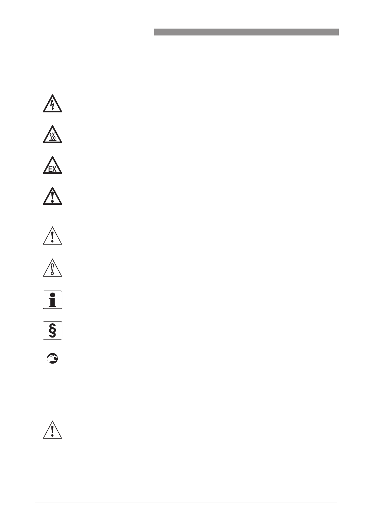
1.3.5 Warnings and symbols used
Safety warnings are indicated by the following symbols.
DANGER!
This information refers to the immediate danger when working with electricity.
DANGER!
This warning refers to the immediate danger of burns caused by heat or hot surfaces.
DANGER!
This warning refers to the immediate danger when using this device in a hazardous atmosphere.
DANGER!
These warnings must be observed without fail. Even partial disregard of this warning can lead to
serious health problems and even death. There is also the risk of seriously damaging the device
or parts of the operator's plant.
GA24
WARNING!
Disregarding this safety warning, even if only in part, poses the risk of serious health problems.
There is also the risk of damaging the device or parts of the operator's plant.
CAUTION!
Disregarding these instructions can result in damage to the device or to parts of the operator's
plant.
INFORMATION!
These instructions contain important information for the handling of the device.
LEGAL NOTICE!
This note contains information on statutory directives and standards.
• HANDLING
HANDLING
HANDLINGHANDLING
This symbol designates all instructions for actions to be carried out by the operator in the
specified sequence.
i RESULT
RESULT
RESULTRESULT
This symbol refers to all important consequences of the previous actions.
1.4 Safety instructions for the operator
WARNING!
In general, devices from the manufacturer may only be installed, commissioned, operated and
maintained by properly trained and authorized personnel.
This document is provided to help you establish operating conditions, which will permit safe and
efficient use of this device.
8
www.krohne.com 02/2011 - 4001229901 MA GA24 R01 en
Page 9
GA24
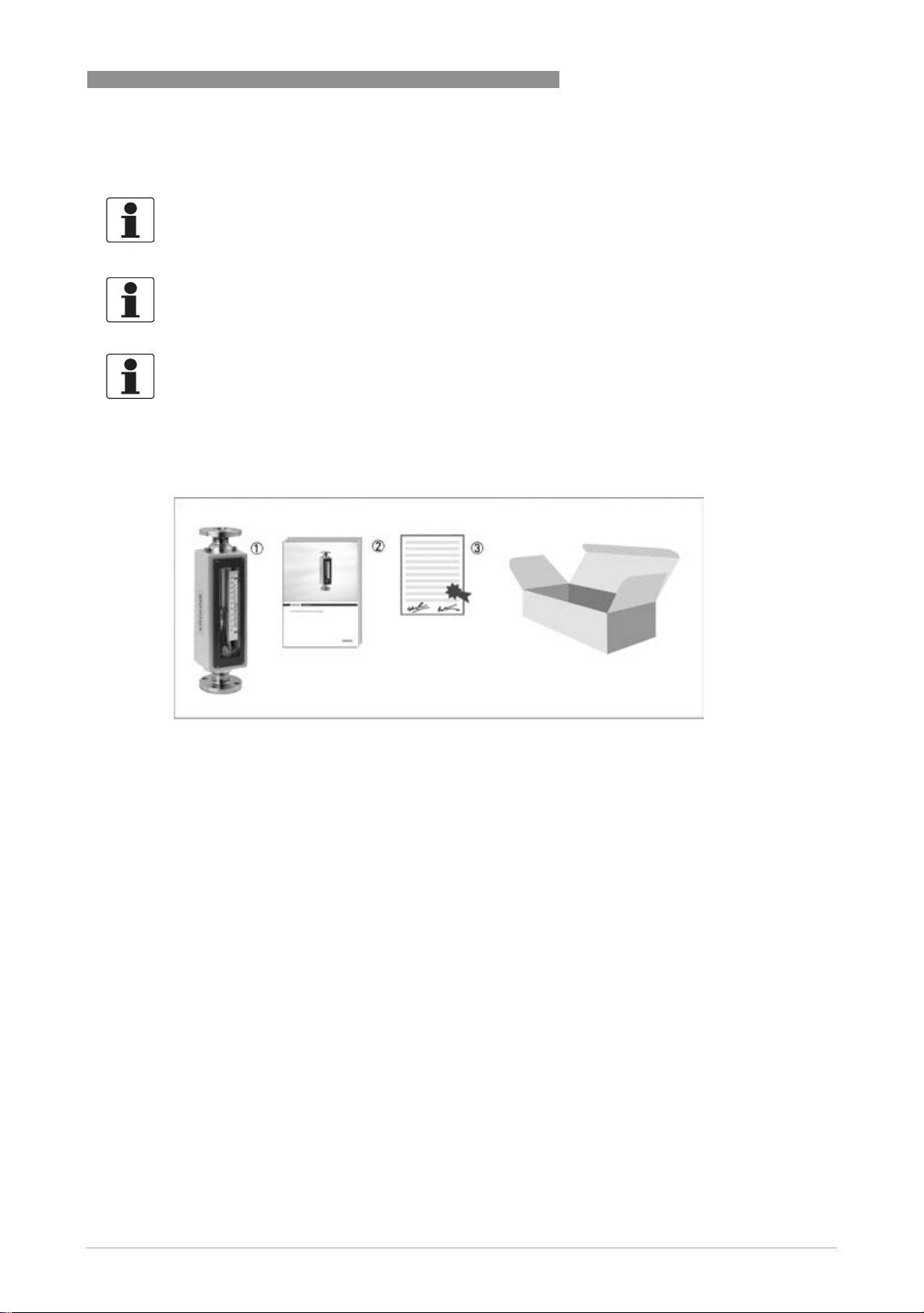
2.1 Scope of delivery
INFORMATION!
Inspect the cartons carefully for damage or signs of rough handling. Report damage to the
carrier and to the local office of the manufacturer.
INFORMATION!
Check the packing list to check if you received completely all that you ordered.
INFORMATION!
Look at the device nameplate to ensure that the device is delivered according to your order.
Check for the correct supply voltage printed on the nameplate.
DEVICE DESCRIPTION 2
Figure 2-1: Scope of delivery
1 Measuring device in ordered version
2 Manual
3 Certificates, calibration report (supplied to order only)
www.krohne.com02/2011 - 4001229901 MA GA24 R01 en
9
Page 10

2 DEVICE DESCRIPTION
2.2 Nameplate
INFORMATION!
Look at the device nameplate to ensure that the device is delivered according to your order.
Check for the correct supply voltage printed on the nameplate.
1 Device type
2 Manufacturer
3 Internet site
4 Notified ATEX body
5 Note manual
6 Ex data
7 Serial Number
8 Year of manufacture
9 PED data
10 Sizing data: temperature & pressure
GA24
Additional markings on the measuring device
• SO - sales order / item
• Tag-No - Measuring point identifier
• PA - KROHNE order
• AC - article code
2.3 Description code
The description code* GA24 consists of the following elements:
1 Type series measuring unit GA24
2 Material of connection
R - stainless steel
PTFE - stainless steel with PTFE lining
3 Limit switch
K1 - One limit switch
K2 - Two limit switches
10
* positions which are not needed are omitted (no blank positions)
www.krohne.com 02/2011 - 4001229901 MA GA24 R01 en
Page 11

GA24
3.1 Notes on installation
INFORMATION!
Inspect the cartons carefully for damage or signs of rough handling. Report damage to the
carrier and to the local office of the manufacturer.
INFORMATION!
Check the packing list to check if you received completely all that you ordered.
INFORMATION!
Look at the device nameplate to ensure that the device is delivered according to your order.
Check for the correct supply voltage printed on the nameplate.
3.2 Storage
• Store the device in a dry and dust-free location.
• Avoid lasting direct exposure to the sun.
• Store the device in its original packing.
• The permissible storage temperature for standard devices is -40...+80°C / -40...+176°F.
INSTALLATION 3
3.3 Installation condtitions
CAUTION!
When installing the device in the piping, the following points must be observed:
•
The variable area flowmeter must be installed vertically (measuring principle). Flow direction
from bottom to top. For installation recommendations please refer also to VDI/VDE 3513
Sheet 3.
•
Before connecting, blow or flush out the pipes leading to the device.
•
Pipes for gas flow need to be dried before the device is installed.
•
Use connectors suitable for the particular device version.
•
Align the pipes centrically with the connection bores on the measuring device so they are free
of stresses.
•
If necessary, support the pipeline to reduce vibrations being transmitted to the measuring
device.
•
Do not lay signal cables directly next to cables for the power supply.
3.4 Transport locks
A plastic rod is fitted to secure the float during transportation. This must be removed prior to
starting up.
Remove the protective cover on the top flange and the rod lock from the glass.
www.krohne.com02/2011 - 4001229901 MA GA24 R01 en
11
Page 12

4 ELECTRICAL CONNECTIONS
4.1 Safety instructions
DANGER!
All work on the electrical connections may only be carried out with the power disconnected. Take
note of the voltage data on the nameplate!
DANGER!
Observe the national regulations for electrical installations!
DANGER!
For devices used in hazardous areas, additional safety notes apply; please refer to the Ex
documentation.
WARNING!
Observe without fail the local occupational health and safety regulations. Any work done on the
electrical components of the measuring device may only be carried out by properly trained
specialists.
GA24
INFORMATION!
Look at the device nameplate to ensure that the device is delivered according to your order.
Check for the correct supply voltage printed on the nameplate.
4.2 Limit switches GA24
The flowmeters GA24 can be equipped with a maximum of two bistable limit switches.
Bistable function: Stable switching when passing through the switching point
Use, selection and function - see Technical Data
12
Figure 4-1: Types of limit switch
1 MS 14/I - floating, bistable reed contact
2 TG21 - bistable, with integrated switching lug and slotted proximity switch
www.krohne.com 02/2011 - 4001229901 MA GA24 R01 en
Page 13

GA24
4.2.1 MS14 limit switch connection
Figure 4-2: Connection limit switch type MS14
1 Connection Reed-switch
2 Connection Receiver device
3 Terminal connection (potential-free)
The switching function requires a float with integrated magnet.
ELECTRICAL CONNECTIONS 4
4.2.2 TG21 limit switch connection
Figure 4-3: Connection limit switch type TG21
1 Terminal -
2 Terminal +
The TG 21 is adapted for switch amplifiers with an intrinsically safe circuit as per DIN EN 50227
NAMUR.
The TG 21 includes an inductive slotted proximity switch with bistable switching characteristics.
The slotted proximity switch is activated by the immersion of an aluminum lug. The magnet of
the immersion lug is moved by the magnet in the float.
The switching function requires a float with integrated magnet.
www.krohne.com02/2011 - 4001229901 MA GA24 R01 en
13
Page 14

4 ELECTRICAL CONNECTIONS
4.3 Limit switch settings
4.3.1 Limit switch settings MS14
• Undo bracket screw 1 and set switching position
• Secure bracket screw 1
The distance between the limit switch and the casing is factory set with clamp screw 2 so that
the limit switch touches the glass taper at the maximum switching point.
GA24
The limit switch must be rotated 180° to reach the lower range of the scale.
4.3.2 Limit switch settings TG21
• Undo bracket screw 1 and set switching position
• Secure bracket screw 1
The distance between the limit switch and the casing is factory set at approx. 1 mm (0.039") with
the clamping screw 2.
14
www.krohne.com 02/2011 - 4001229901 MA GA24 R01 en
Page 15

GA24
4.4 Limit switch function reversal
4.4.1 Limit switch function reversal MS14
The contact function can be changed by reconnecting the reed cartridge screwed into the
cartridge housing:
• Closing as flow increases:Arrow on reed cartridge points towards measuring glass.
• Closing as flow decreases:Arrow on reed cartridge points away from measuring glass.
4.4.2 Limit switch function reversal TG21
ELECTRICAL CONNECTIONS 4
The contact function can be changed from normally open to normally closed by moving the
position of the slotted proximity switch 3.
1 Magnet
2 Contact vane
3 Slot sensor
4 Counter-magnet
5 Grub screw
6 Detaching screw slot sensor
Once the screw 6 has been undone, the slotted proximity switch 3 can be moved to the other
end position.
If there is the possibility of vibrations triggering an improper switching operation, the strength of
the force closure between the adjustment magnet and counter magnet 4 can be adjusted on the
immersion lug 2 using the grub screw 5.
The switching reproducibility is < 3% of the final measuring range value and is affected by the
strength of the force closure.
www.krohne.com02/2011 - 4001229901 MA GA24 R01 en
15
Page 16

5 SERVICE
5.1 Maintenance
The flowmeter should be checked for signs of dirt, corrosion, mechanical wear and damage to
the measuring glass during routine maintenance of the system and pipelines. We advise that
inspections be carried out at least once per year.
CAUTION!
Pressurized pipes have to be depressurized before removing the device.
Empty pipes as completely as possible.
In the case of devices used for measuring aggressive or hazardous media, appropriate safety
precautions must be taken with regard to residual liquids in the measuring unit.
Only the connecting couplings of the pipeline may be undone.
Always use new seals when fitting the measuring device in the pipe.
Avoid electrostatic charges when cleaning the surfaces (e.g. sight window)!
Test the leak tightness using suitable means prior to starting up the measuring device again.
5.2 Spare parts availability
The manufacturer adheres to the basic principle that functionally adequate spare parts for each
device or each important accessory part will be kept available for a period of 3 years after
delivery of the last production run for the device.
GA24
This regulation only applies to spare parts which are subject to wear and tear under normal
operating conditions.
5.3 Availability of services
The manufacturer offers a range of services to support the customer after expiration of the
warranty. These include repair, maintenance, technical support and training.
INFORMATION!
For more precise information, please contact your local representative.
16
www.krohne.com 02/2011 - 4001229901 MA GA24 R01 en
Page 17

GA24
5.4 Returning the device to the manufacturer
5.4.1 General information
This device has been carefully manufactured and tested. If installed and operated in accordance
with these operating instructions, it will rarely present any problems.
CAUTION!
Should you nevertheless need to return a device for inspection or repair, please pay strict
attention to the following points:
•
Due to statutory regulations on environmental protection and safeguarding the health and
safety of our personnel, manufacturer may only handle, test and repair returned devices that
have been in contact with products without risk to personnel and environment.
•
This means that the manufacturer can only service this device if it is accompanied by the
following certificate (see next section) confirming that the device is safe to handle.
CAUTION!
If the device has been operated with toxic, caustic, flammable or water-endangering products,
you are kindly requested:
•
to check and ensure, if necessary by rinsing or neutralizing, that all cavities are free from
such dangerous substances,
•
to enclose a certificate with the device confirming that is safe to handle and stating the
product used.
SERVICE 5
www.krohne.com02/2011 - 4001229901 MA GA24 R01 en
17
Page 18

5 SERVICE
5.4.2 Form (for copying) to accompany a returned device
Company: Address:
Department: Name:
Tel. no.: Fax no.:
Manufacturer's order no. or serial no.:
The device has been operated with the following medium:
GA24
This medium is: water-hazardous
toxic
caustic
flammable
We checked that all cavities in the device are free from such
substances.
We have flushed out and neutralized all cavities in the
device.
We hereby confirm that there is no risk to persons or the environment through any residual media
contained in the device when it is returned.
Date: Signature:
Stamp:
5.5 Disposal
CAUTION!
Disposal must be carried out in accordance with legislation applicable in your country.
18
www.krohne.com 02/2011 - 4001229901 MA GA24 R01 en
Page 19

GA24
6.1 Operating principle
The flowmeter operates on the float measuring principle
The measuring unit consists of a glass cone in which a float can move freely up and down.
The flow goes from bottom to top.
The float changes position so that the lifting force acting on it F1 is in equilibrium with the form
drag F2 and its weight F3: F3 = F1 + F2
TECHNICAL DATA 6
The height of the float is read on the scale of the measuring glass and indicates the flow rate.
The top edge of the float marks the reading line for flow values.
www.krohne.com02/2011 - 4001229901 MA GA24 R01 en
19
Page 20

6 TECHNICAL DATA
6.2 Technical data
INFORMATION!
•
The following data is provided for general applications. If you require data that is more
relevant to your specific application, please contact us or your local representative.
•
Additional information (certificates, special tools, software,...) and complete product
documentation can be downloaded free of charge from the website (Download Center).
Measuring system
Application range Flow measurement of liquids, gases and vapors
Operating method / measuring principle Variable area measuring principle
Measured value
Measured value
Measured valueMeasured value
Primary measured value Float position
Secondary measured value Operating and standard volumetric flow
Measuring accuracy
Measuring accuracy
Measuring accuracy Measuring accuracy
Directive VDI / VDE 3513, sheet 2 (qG =50%)
Measuring accuracy 1.o%
GA24
Operating conditions
Temperature
Temperature
TemperatureTemperature
Max. operating temperature TS -40...+120°C / -40...+248°F
Pressure
Pressure
PressurePressure
Max. permitted operating gauge pressure PS at TS
= 100°C
Test pressure PT Pressure equipment directive 97/23/EC or
DN15, DN25 10 bar 1
DN40 9 bar 1
DN50 7 bar 1
Pressure equipment directive 97/23/EC
AD 2000-HP30
Installation conditions
Inlet condition, run ≥ 5 x DN
Outlet condition, run ≥ 3 x DN
1 other pressures upon request
20
www.krohne.com 02/2011 - 4001229901 MA GA24 R01 en
Page 21

GA24
TECHNICAL DATA 6
Materials
Flange connection GA24/R Stainless steel 1.4404 (316 L)
Flange connection GA24/PTFE Stainless steel 1.14404 (316 L) with a liner made of
PTFE
Housing Steel plate housing (zinc-plated with epoxy/polyester
coating)
Measuring cone Borosilicate glass
Suspended solid particle Stainless steel 1.4571 (316 Ti) or Hastelloy C2000
PTFE/insert or TFM (PTFE)
Aluminum
Polypropylen (PP)
Suspended solid particle and insert PVDF (conforms to FDA)
Seals Neoprene
PTFE Scherring
PTFE sleeve
Temperatures
Temperatures
TemperaturesTemperatures
DANGER!
For devices to be used in hazardous areas, special temperature ranges apply. These can be
found in the separate instructions.
Max. measuring temperature T
Max. ambient temperature T
1 higher temperatures on request
m
amb.
-40...+120°C 1 -40...+248°F
-20...+100°C -4...+212°F
Types of limit switches
Type Switching
function
MS 14/A bistable 2-wire, floating Reed contact Float with magnet
TG 21 bistable 2-wire NAMUR Slotted proximity
Connection Shape Note
required
switch
Float with magnet
required
www.krohne.com02/2011 - 4001229901 MA GA24 R01 en
21
Page 22

6 TECHNICAL DATA
Limit switch use
Size Cone no. Limit switch Size Cone no. Limit switch
DN15 N 18.07 MS14/A DN25 N 21.09 MS14/A TG21
N 18.09 MS14/A N 21.13 MS14/A TG21
N 18.13 MS14/A N 21.18 MS14/A TG21
N 19.09 MS14/A N 21.25 MS14/A TG21
N 19.13 MS14/A DN40 N 41.09 MS14/A TG21
N 19.19 MS14/A N 41.13 MS14/A TG21
N 19.26 MS14/A N 41.19 MS14/A TG21
Technical Data Limit Switches
GA24
DN50 N 51.10 MS14/A TG21
N 51.15 MS14/A TG21
N 51.21 MS14/A TG21
Technical data MS14
Contact type Normally open or normally closed, can be reconnected
Switching reproducibility < 2% of full-scale range
Contact rating 12VA
max. turn-on voltage 30VDC
Max. switching current 0,5A
Ambient temperature -20...+85°C / -4...+185 °F
Protection category acc. to IEC 60529 / EN
529
IP44
Technical data TG21
Rated voltage 8VDC
Current consumption, active surface open 3mA
Current consumption, active surface
covered
Ambient temperature -25...+100°C / -13...+212 °F
Protection category acc. to IEC 60529 / EN
529
1mA
IP 67 (NEMA 6)
22
www.krohne.com 02/2011 - 4001229901 MA GA24 R01 en
Page 23

GA24
6.3 Dimensions and weights
Dimensions
Nominal size a b c d
DN Inch mm Inch mm Inch mm Inch mm Inch
15 1/2" 500 19.7 300 11.8 84 3.31 82 3.23
25 1" 500 19.7 300 11.8 105 4.13 102 4.02
40 1 1/2" 500 19.7 300 11.8 125 4.92 122 4.80
50 2" 500 19.7 300 11.8 165 6.50 147 5.74
TECHNICAL DATA 6
Weights
approx. kg approx. Ib
DN15 6 13
DN25 10 22
DN40 13 29
DN50 18 40
Process connection
Connection
dimensions according
to
Flanged connections EN 1092 DN15, DN25 PN25
EN 1092 DN40 DN50 PN10
ASME B16.5 1/2"...2" Class 150 lb / RF
ASME B16.5 1/2"...2" Class 300 lb / RF
Connection Pressure class
www.krohne.com02/2011 - 4001229901 MA GA24 R01 en
23
Page 24

6 TECHNICAL DATA
6.4 Measuring ranges
Measuring span 10 : 1 Flow values 100%
Reference condition: Water 20°C / Air 20°C - 1.013 bar abs.
Float materials: 1 Stainless Steel or Hastelloy® - 2 PTFE - 3 TFM - 4 Aluminium - 5 Polypropylen (PP)
Materials → 1 2 3 1 3 4 5 1 2 3 4 5
GA24
Cone ↓ Flow water [l/h]
N 18.07 DN15 40 25 13 1.5 0.6 0.8 0.5 9 6 2 3 1
N 18.09 63 40 22 2.2 0.95 1.2 0.7 9 7 3 3 2
N 18.13 100 63 35 3 1.5 1.8 1.2 9 8 3 4 2
N 19.09 160 100 55 5 2.2 2.8 1.8 13 9 4 5 2
N 19.13 250 160 85 8 3.3 4.5 2.8 16 11 4 5 2
N 19.19 400 250 140 - - - - 21 14 5 - -
N 19.26 630 400 230 - - - - 27 17 6 - -
N 21.09 DN25 630 400 230 18 1 9 11 7 22 14 6 8 3
N 21.13 1000 630 350 28 1 14 18 12 23 17 6 8 4
N 21.18 1600 1000 600 49 1 - 28 1 17 1 26 25 7 10 6
N 21.25 2500 1600 950 70 1 - 42 1 26 1 33 40 8 12 9
N 41.09 DN40 1600 1000 600 45 1 22 28 18 32 18 9 11 5
N 41.13 2500 1600 900 70 1 36 45 1 28 1 34 20 10 12 5
N 41.19 4000 2500 1500 128 1 - 76 1 46 1 38 24 11 15 8
N 51.10 DN50 4000 2500 1500 120 1 56 70 45 43 25 12 15 7
N 51.15 6300 4000 2400 190 1 90 110 1 70 1 47 30 13 16 7
N 51.21 10000 6300 3500 310 1 - 170 1 118 1 55 42 14 20 10
1 only possible with guided float
Flow air [m3/h]
Max. pressure loss [mbar]
24
INFORMATION!
The operating pressure should be at least double the pressure loss for liquids and five times for
gases. The indicated pressure losses are valid for water and air at maximum flow rate.
Conversion to other products or operating data is performed by KROHNE using the calculation
method stipulated by VDI/VDE Directive 3513.
www.krohne.com 02/2011 - 4001229901 MA GA24 R01 en
Page 25

GA24
Measuring span 10 : 1 Flow values 100%
Reference condition: Water 68°F / Air 68°F - 14.7 psi
Float materials: 1 Stainless Steel or Hastelloy® - 2 PTFE - 3 TFM - 4 Aluminium - 5 Polypropylen (PP)
TECHNICAL DATA 6
Materials → 1 2 3 1 3 4 5 1 2 3 4 5
Cone ↓ Flow, water [gph] Flow, air [scfm] Max. pressure loss [psi]
N 18.07 DN15 10.6 6.6 3.43 0.93 0.37 0.5 0.31 0.1 0.1 0.03 0.04 0.02
N 18.09 16.6 10.6 5.81 1.36 0.59 1.2 0.43 0.1 0.1 0.04 0.04 0.03
N 18.13 26.4 16.6 9.25 1.86 0.93 0.74 0.74 0.1 0.1 0.04 0.06 0.03
N 19.09 42.3 26.4 14.5 3.1 1.36 1.7 1.1 0.19 0.13 0.06 0.07 0.03
N 19.13 66.0 42.3 22.5 4.96 2.05 2.8 1.7 0.2 0.16 0.06 0.07 0.03
N 19.19 105 66.0 37 - - - - 0.3 0.2 0.07 - -
N 19.26 166 106 60.8 - - - - 0.4 0.25 0.09 - -
N 21.09 DN25 166 106 60.8 11.2 1 5.58 6.8 4.3 0.3 0.2 0.09 0.1 0.06
N 21.13 264 166 92.5 17.4 1 8.68 11 7.4 0.3 0.25 0.09 0.1 0.06
N 21.18 423 264 158 30.4 1 - 17 1 10.5 1 0.3 0.3 0.1 0.15 0.9
N 21.25 660 423 251 43.4 1 - 26 1 16 1 0.48 0.58 0.1 0.17 0.13
N 41.09 DN40 423 264 158 27.9 1 13.6 17 11 0.48 0.26 0.1 0.16 0.07
N 41.13 660 423 238 43.4 1 22.3 28 1 17.4 1 0.49 0.29 0.15 0.17 0.07
N 41.19 1057 660 396 79.4 1 - 47 1 28.5 1 0.55 0.35 0.16 0.22 0.1
N 51.10 DN50 1057 660 396 74.4 1 34.7 43.4 27.9 0.62 0.36 0.17 0.22 0.1
N 51.15 1664 1057 634 118 1 55.8 68 1 43.4 1 0.68 0.44 0.19 0.23 0.1
N 51.21 2642 1664 925 192 1 - 105 1 73 1 0.8 0.61 0.2 0.29 0.15
1 only possible with guided float
INFORMATION!
The operating pressure should be at least double the pressure loss for liquids and five times for
gases. The specified pressure losses are valid for water and air at maximum flow rate.
Conversion to other products or operating data is performed by KROHNE using the calculation
method stipulated in VDI/VDE Directive 3513.
www.krohne.com02/2011 - 4001229901 MA GA24 R01 en
25
Page 26

7 NOTES
GA24
26
www.krohne.com 02/2011 - 4001229901 MA GA24 R01 en
Page 27

GA24
NOTES 7
www.krohne.com02/2011 - 4001229901 MA GA24 R01 en
27
Page 28

KROHNE product overview
• Electromagnetic flowmeters
• Variable area flowmeters
• Ultrasonic flowmeters
• Mass flowmeters
• Vortex flowmeters
• Flow controllers
• Level meters
• Temperature meters
• Pressure meters
• Analysis products
• Measuring systems for the oil and gas industry
• Measuring systems for sea-going tankers
Head Office KROHNE Messtechnik GmbH
Ludwig-Krohne-Str. 5
D-47058 Duisburg (Germany)
Tel.:+49 (0)203 301 0
Fax:+49 (0)203 301 10389
info@krohne.de
© KROHNE 02/2011 - 4001229901 MA GA24 R01 en - Subject to change without notice.
The current list of all KROHNE contacts and addresses can be found at:
www.krohne.com
 Loading...