

Page 1
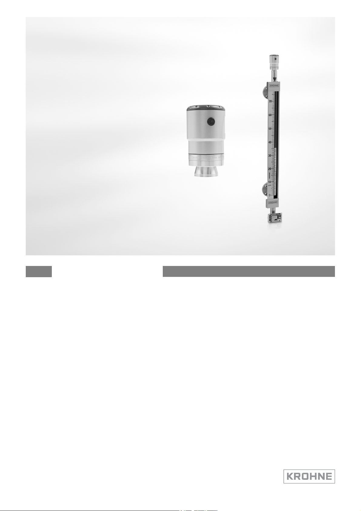
OPTIWAVE 1010
Handbook
2-wire / 6 GHz Radar (FMCW) Level Meter
for continuous measuring of clean liquids in the BM 26 Advanced (Magnetic Level
Indicator)
© KROHNE 09/2014 - 4003537401 - MA OPTIWAVE 1010 R01 en
Page 2

: IMPRINT :::::::::::::::::::::::::::::::::::::::
All rights reserved. It is prohibited to reproduce this documentation, or any part thereof, without
the prior written authorisation of KROHNE Messtechnik GmbH.
Subject to change without notice.
Copyright 2014 by
KROHNE Messtechnik GmbH - Ludwig-Krohne-Str. 5 - 47058 Duisburg (Germany)
2
www.krohne.com 09/2014 - 4003537401 - MA OPTIWAVE 1010 R01 en
Page 3

OPTIWAVE 1010
CONTENTS
1 Safety instructions 6
1.1 Software history ............................................................................................................... 6
1.2 Intended use ..................................................................................................................... 6
1.3 Certification ...................................................................................................................... 7
1.4 Radio approvals ................................................................................................................ 7
1.4.1 European Union (EU)............................................................................................................... 7
1.4.2 U.S.A. and Canada................................................................................................................... 8
1.5 Safety instructions from the manufacturer ..................................................................... 9
1.5.1 Copyright and data protection ................................................................................................ 9
1.5.2 Disclaimer ............................................................................................................................... 9
1.5.3 Product liability and warranty .............................................................................................. 10
1.5.4 Information concerning the documentation......................................................................... 10
1.5.5 Warnings and symbols used................................................................................................. 11
1.6 Safety instructions for the operator............................................................................... 11
2 Device description 12
2.1 Scope of delivery............................................................................................................. 12
2.2 Device description .......................................................................................................... 13
2.3 Visual Check ................................................................................................................... 14
2.4 Nameplates .................................................................................................................... 15
2.4.1 Nameplate (example)............................................................................................................ 15
3 Installation 16
3.1 General notes on installation ......................................................................................... 16
3.2 Storage ........................................................................................................................... 16
3.3 Transport ........................................................................................................................ 17
3.4 Pre-installation requirements ....................................................................................... 17
3.5 Pressure and temperature ranges ................................................................................ 17
3.6 Recommended mounting position ................................................................................. 20
3.7 Mounting restrictions ..................................................................................................... 20
3.8 Stilling wells ................................................................................................................... 21
3.9 How to attach the weather protection to the device...................................................... 22
4 Electrical connections 23
4.1 Safety instructions.......................................................................................................... 23
4.2 Electrical installation: 2-wire, loop-powered ................................................................ 23
4.3 Electrical connection for current output ....................................................................... 24
4.3.1 Non-Ex devices ..................................................................................................................... 24
4.3.2 Devices for hazardous locations........................................................................................... 24
4.4 Protection category ........................................................................................................24
4.5 Networks ........................................................................................................................ 25
4.5.1 General information.............................................................................................................. 25
4.5.2 Point-to-point connection..................................................................................................... 25
4.5.3 Multi-drop networks ............................................................................................................. 26
www.krohne.com09/2014 - 4003537401 - MA OPTIWAVE 1010 R01 en
3
Page 4

CONTENTS
OPTIWAVE 1010
5 Start-up 27
5.1 How to start the device................................................................................................... 27
5.1.1 Start-up checklist ................................................................................................................. 27
5.1.2 How to start the device ......................................................................................................... 27
5.2 Operating concept ..........................................................................................................27
5.3 Remote communication with PACTware™ .................................................................... 28
5.3.1 General notes........................................................................................................................ 28
5.3.2 Software installation............................................................................................................. 28
5.4 Remote communication with the AMS™ Device Manager............................................. 29
6 Operation 30
6.1 Software configuration ................................................................................................... 30
6.1.1 General notes........................................................................................................................ 30
6.1.2 Procedure.............................................................................................................................. 30
6.2 How to load settings from the device to PACTware™ ................................................... 31
6.3 Menu overview................................................................................................................ 32
6.4 Device settings ............................................................................................................... 33
6.4.1 Supervisor access rights ...................................................................................................... 33
6.4.2 How to change device settings ............................................................................................. 33
6.4.3 Data about menu items and parameters (online Help)........................................................ 34
6.4.4 Basic parameters.................................................................................................................. 35
6.4.5 Signal output ......................................................................................................................... 36
6.4.6 Import / export ...................................................................................................................... 36
6.4.7 Application............................................................................................................................. 37
6.4.8 HART...................................................................................................................................... 38
6.5 Status and error messages............................................................................................ 39
6.5.1 Device status......................................................................................................................... 39
6.5.2 Error handling....................................................................................................................... 40
7 Service 44
7.1 Periodic maintenance..................................................................................................... 44
7.2 Service warranty............................................................................................................. 44
7.3 Spare parts availability...................................................................................................44
7.4 Availability of services .................................................................................................... 44
7.5 Returning the device to the manufacturer..................................................................... 45
7.5.1 General information.............................................................................................................. 45
7.5.2 Form (for copying) to accompany a returned device............................................................ 46
7.6 Disposal .......................................................................................................................... 46
8 Technical data 47
8.1 Measuring principle........................................................................................................47
8.2 Technical data................................................................................................................. 48
8.3 Minimum power supply voltage ..................................................................................... 53
8.4 Pressure ratings............................................................................................................. 54
8.5 Dimensions and weights ................................................................................................ 55
4
www.krohne.com 09/2014 - 4003537401 - MA OPTIWAVE 1010 R01 en
Page 5

OPTIWAVE 1010
CONTENTS
9 Description of HART interface 58
9.1 General description ........................................................................................................58
9.2 Software description ...................................................................................................... 58
9.3 Connection variants........................................................................................................58
9.3.1 Point-to-Point connection - analogue / digital mode........................................................... 59
9.3.2 Multi-Drop connection (2-wire connection) ......................................................................... 59
9.4 HART® device variables ................................................................................................. 59
9.5 Field Communicator 375/475 (FC 375/475) ................................................................... 59
9.5.1 Installation ............................................................................................................................ 59
9.5.2 Operation............................................................................................................................... 60
9.6 Asset Management Solutions (AMS) .............................................................................. 60
9.6.1 Installation ............................................................................................................................ 60
9.6.2 Operation............................................................................................................................... 60
9.6.3 Parameter for the basic configuration ................................................................................. 60
9.7 Field Device Tool / Device Type Manager (FDT / DTM).................................................. 61
9.7.1 Installation ............................................................................................................................ 61
9.7.2 Operation............................................................................................................................... 61
9.8 Process Device Manager (PDM)..................................................................................... 61
9.8.1 Installation ............................................................................................................................ 61
9.8.2 Operation............................................................................................................................... 61
9.9 HART® menu tree for Basic-DD .................................................................................... 62
9.9.1 Overview Basic-DD menu tree (positions in menu tree)...................................................... 62
9.9.2 Basic-DD menu tree (details for settings)............................................................................ 62
9.10 HART® menu tree for AMS........................................................................................... 62
9.10.1 Overview AMS menu tree (positions in menu tree) ............................................................ 62
9.10.2 AMS menu tree (details for settings).................................................................................. 63
9.11 HART® menu tree for PDM .......................................................................................... 64
9.11.1 Overview PDM menu tree (positions in menu tree)............................................................ 64
9.11.2 PDM menu tree (details for settings) ................................................................................. 65
10 Appendix 67
10.1 Order code .................................................................................................................... 67
10.2 Spare parts ................................................................................................................... 70
10.3 Accessories................................................................................................................... 71
10.4 Glossary ........................................................................................................................ 72
11 Notes 75
www.krohne.com09/2014 - 4003537401 - MA OPTIWAVE 1010 R01 en
5
Page 6
1 SAFETY INSTRUCTIONS
1.1 Software history
"Firmware revision" agrees with NAMUR NE 53. It is a series of numbers used to record the
revision status of embedded software (firmware) in electronic equipment assemblies. It gives
data on the type of changes made and the effect that changes have on compatibility.
Data about software revisions is shown in the DTM for PACTware™. For more data,. If it is not
possible to refer to data in the software, record the serial number of the device (given on the
device nameplate) and speak to the supplier.
OPTIWAVE 1010
Release
date
YYYY-MM-DDConverter and
Printed circuit
assembly
sensor board
1.2 Intended use
CAUTION!
Responsibility for the use of the measuring devices with regard to suitability, intended use and
corrosion resistance of the used materials against the measured fluid lies solely with the
operator.
INFORMATION!
The manufacturer is not liable for any damage resulting from improper use or use for other than
the intended purpose.
This radar level transmitter measures distance and level of liquids. It does not touch the
measured product.
This radar level transmitter can only be used if it is correctly installed and aligned on a bypass
chamber or a stilling well. The bypass chamber or stilling well must be metallic and electrically
conductive. The stilling well must installed in a metal or reinforced concrete tank to prevent
radio frequency interference.
Firmware
revision
1.00.xx 400xxxxx01 - HB OPTIWAVE
Hardware
revision
Changes and
compatibility
Documentation
1010 R01
6
www.krohne.com 09/2014 - 4003537401 - MA OPTIWAVE 1010 R01 en
Page 7
OPTIWAVE 1010
1.3 Certification
DANGER!
For devices used in hazardous areas, additional safety notes apply; please refer to the Ex
documentation.
In accordance with the commitment to customer service and safety, the device
described in this document meets the following safety requirements:
• Electromagnetic Compatibility (EMC) Directive 2004/108/EC in conjunction with EN 61326-1
(2013).
• Radio Equipment and Telecommunications Terminal Equipment (R & TTE) Directive
1999/05/EC in conjunction with ETSI EN 302 372 (2006). For more data, refer to
Union (EU)
• Low-Voltage Directive 2006/95/EC in conjunction with EN 61010-1 (2001).
SAFETY INSTRUCTIONS 1
European
on page 7.
All devices are based on the CE marking and meet the requirements of NAMUR Guideline NE 21,
NE 43 and NE 53.
1.4 Radio approvals
1.4.1 European Union (EU)
LEGAL NOTICE!
This level transmitter is intended for installation in closed tanks. It meets the requirements of
the R & TTE (Radio Equipment and Telecommunications Terminal Equipment) Directive
1999/05/EC for use in the member countries of the EU.
An industry agreement includes approval for use of the frequency band (5.7...6.7 GHz) in
industrial environments.
According to article 6.4 of the R&TTE Directive, the product is marked by the CE sign + notified
body number (0682) + Class II identifier (= alert sign).
Refer to EN 302372 for installation conditions.
www.krohne.com09/2014 - 4003537401 - MA OPTIWAVE 1010 R01 en
7
Page 8
1 SAFETY INSTRUCTIONS
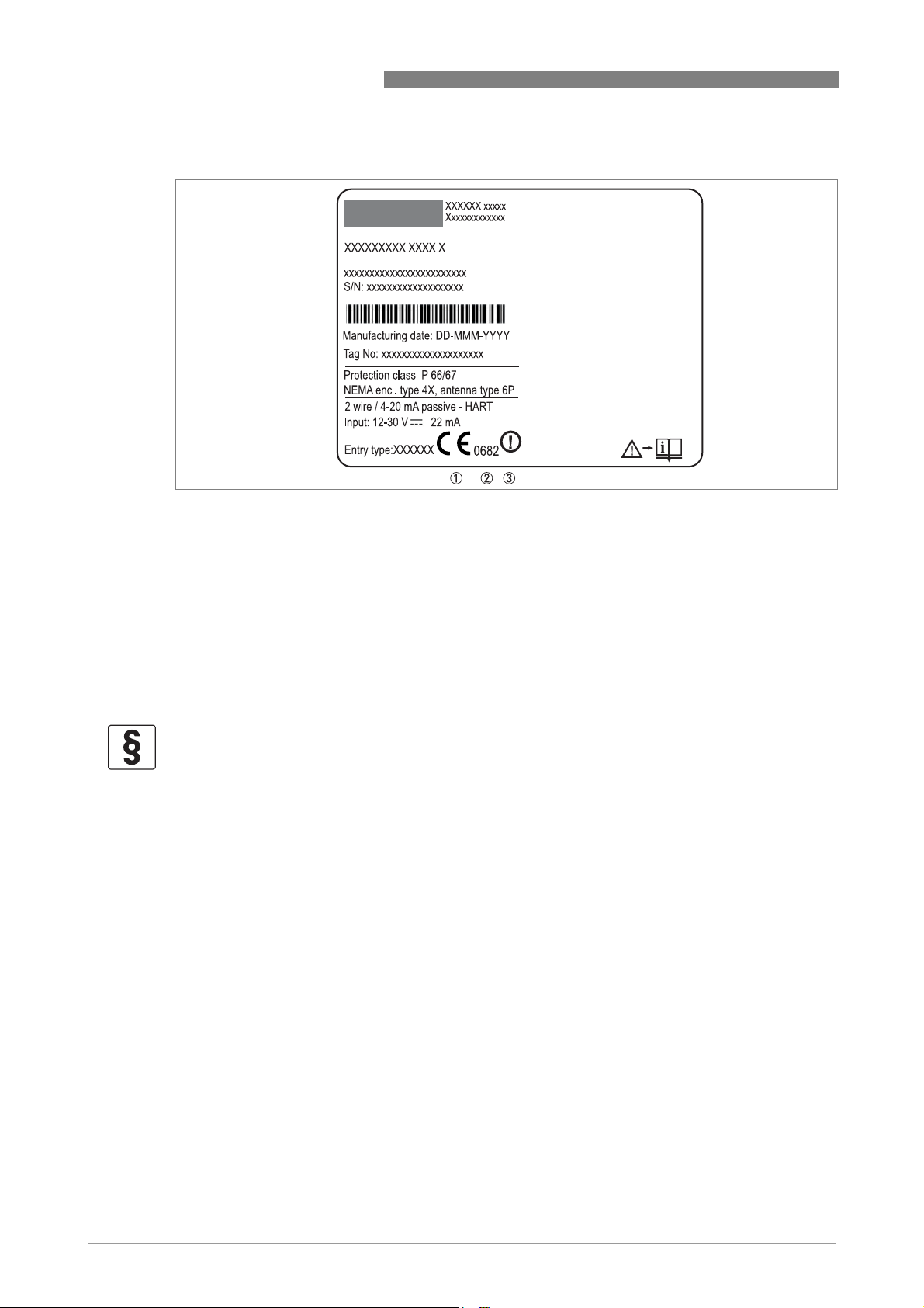
Figure 1-1: Radio approval information on the nameplate
1 CE sign
2 Notified body number (0682 = CETECOM ICT Services GmbH)
3 Class II identifier
OPTIWAVE 1010
According to ETSI EN 302 372 (2006-04), the radiated power outside a metallic tank is less than
-30 dBm.
The radio approval report is given on the DVD-ROM supplied with the device.
1.4.2 U.S.A. and Canada
LEGAL NOTICE!
English: This device complies with Part 15 of the FCC Rules and with RSS-210 of Industry
Canada. Operation is subject to the following two conditions:
1. This device may not cause harmful interference, and
2. This device must accept any interference received, including interference which may cause un-
desired operation.
Français: Le présent appareil est conforme aux CNR d'Industrie Canada applicables aux
appareils radio exempts de licence. L'exploitation est autorisée aux deux conditions suivantes:
1. l'appareil ne doit pas produire de brouillage, et
2. l'utilisateur de l'appareil doit accepter tout brouillage radioélectrique subi, même si le brouil-
lage est susceptible d'en compromettre le fonctionnment.
Changes or modifications made to this equipment not expressly approved by the manufacturer
may void the FCC and IC authorizations to operate this equipment.
This legal information is shown on a label on the side of the device.
The radio approval report is given on the DVD-ROM supplied with the device.
8
www.krohne.com 09/2014 - 4003537401 - MA OPTIWAVE 1010 R01 en
Page 9

OPTIWAVE 1010
1.5 Safety instructions from the manufacturer
1.5.1 Copyright and data protection
The contents of this document have been created with great care. Nevertheless, we provide no
guarantee that the contents are correct, complete or up-to-date.
The contents and works in this document are subject to copyright. Contributions from third
parties are identified as such. Reproduction, processing, dissemination and any type of use
beyond what is permitted under copyright requires written authorisation from the respective
author and/or the manufacturer.
The manufacturer tries always to observe the copyrights of others, and to draw on works created
in-house or works in the public domain.
The collection of personal data (such as names, street addresses or e-mail addresses) in the
manufacturer's documents is always on a voluntary basis whenever possible. Whenever
feasible, it is always possible to make use of the offerings and services without providing any
personal data.
SAFETY INSTRUCTIONS 1
We draw your attention to the fact that data transmission over the Internet (e.g. when
communicating by e-mail) may involve gaps in security. It is not possible to protect such data
completely against access by third parties.
We hereby expressly prohibit the use of the contact data published as part of our duty to publish
an imprint for the purpose of sending us any advertising or informational materials that we have
not expressly requested.
1.5.2 Disclaimer
The manufacturer will not be liable for any damage of any kind by using its product, including,
but not limited to direct, indirect or incidental and consequential damages.
This disclaimer does not apply in case the manufacturer has acted on purpose or with gross
negligence. In the event any applicable law does not allow such limitations on implied warranties
or the exclusion of limitation of certain damages, you may, if such law applies to you, not be
subject to some or all of the above disclaimer, exclusions or limitations.
Any product purchased from the manufacturer is warranted in accordance with the relevant
product documentation and our Terms and Conditions of Sale.
The manufacturer reserves the right to alter the content of its documents, including this
disclaimer in any way, at any time, for any reason, without prior notification, and will not be liable
in any way for possible consequences of such changes.
www.krohne.com09/2014 - 4003537401 - MA OPTIWAVE 1010 R01 en
9
Page 10

1 SAFETY INSTRUCTIONS
1.5.3 Product liability and warranty
The operator shall bear responsibility for the suitability of the device for the specific purpose.
The manufacturer accepts no liability for the consequences of misuse by the operator. Improper
installation or operation of the devices (systems) will cause the warranty to be void. The
respective "Standard Terms and Conditions" which form the basis for the sales contract shall
also apply.
1.5.4 Information concerning the documentation
To prevent any injury to the user or damage to the device it is essential that you read the
information in this document and observe applicable national standards, safety requirements
and accident prevention regulations.
If this document is not in your native language and if you have any problems understanding the
text, we advise you to contact your local office for assistance. The manufacturer can not accept
responsibility for any damage or injury caused by misunderstanding of the information in this
document.
This document is provided to help you establish operating conditions, which will permit safe and
efficient use of this device. Special considerations and precautions are also described in the
document, which appear in the form of icons as shown below.
OPTIWAVE 1010
10
www.krohne.com 09/2014 - 4003537401 - MA OPTIWAVE 1010 R01 en
Page 11
OPTIWAVE 1010
1.5.5 Warnings and symbols used
Safety warnings are indicated by the following symbols.
DANGER!
This warning refers to the immediate danger when working with electricity.
DANGER!
This warning refers to the immediate danger of burns caused by heat or hot surfaces.
DANGER!
This warning refers to the immediate danger when using this device in a hazardous atmosphere.
DANGER!
These warnings must be observed without fail. Even partial disregard of this warning can lead to
serious health problems and even death. There is also the risk of seriously damaging the device
or parts of the operator's plant.
SAFETY INSTRUCTIONS 1
WARNING!
Disregarding this safety warning, even if only in part, poses the risk of serious health problems.
There is also the risk of damaging the device or parts of the operator's plant.
CAUTION!
Disregarding these instructions can result in damage to the device or to parts of the operator's
plant.
INFORMATION!
These instructions contain important information for the handling of the device.
LEGAL NOTICE!
This note contains information on statutory directives and standards.
• HANDLING
This symbol designates all instructions for actions to be carried out by the operator in the
specified sequence.
i RESULT
This symbol refers to all important consequences of the previous actions.
1.6 Safety instructions for the operator
WARNING!
In general, devices from the manufacturer may only be installed, commissioned, operated and
maintained by properly trained and authorized personnel.
This document is provided to help you establish operating conditions, which will permit safe and
efficient use of this device.
www.krohne.com09/2014 - 4003537401 - MA OPTIWAVE 1010 R01 en
11
Page 12
2 DEVICE DESCRIPTION
2.1 Scope of delivery
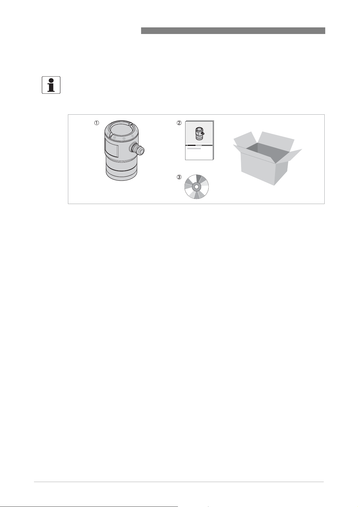
INFORMATION!
Do a check of the packing list to make sure that you have all the elements given in the order.
OPTIWAVE 1010
Figure 2-1: Scope of delivery
1 Device and measuring chamber
2 Quick Start
3 DVD-ROM (including Handbook, Quick Start, Technical Datasheet and related software)
12
www.krohne.com 09/2014 - 4003537401 - MA OPTIWAVE 1010 R01 en
Page 13

OPTIWAVE 1010
2.2 Device description
OPTIWAVE 1010 is an FMCW radar designed for use with the BM 26 Advanced (a magnetic level
indicator or MLI), bypass chamber or stilling well. If the device is used with an MLI, it measures
the distance to the float. If the device is used with a bypass chamber or stilling well, it measures
the distance to the surface of the liquid. Radar is a non-contact technology. For more data about
the measuring principle, refer to
Measuring principle
DEVICE DESCRIPTION 2
on page 47.
Figure 2-2: Radar level transmitter mounted on a magnetic (bypass) level indicator
www.krohne.com09/2014 - 4003537401 - MA OPTIWAVE 1010 R01 en
13
Page 14
2 DEVICE DESCRIPTION
2.3 Visual Check
INFORMATION!
Inspect the packaging carefully for damages or signs of rough handling. Report damage to the
carrier and to the local office of the manufacturer.
OPTIWAVE 1010
Figure 2-3: Visual check
1 Device nameplate (for more data)
2 Process connection data (size and pressure rating, material reference and heat number)
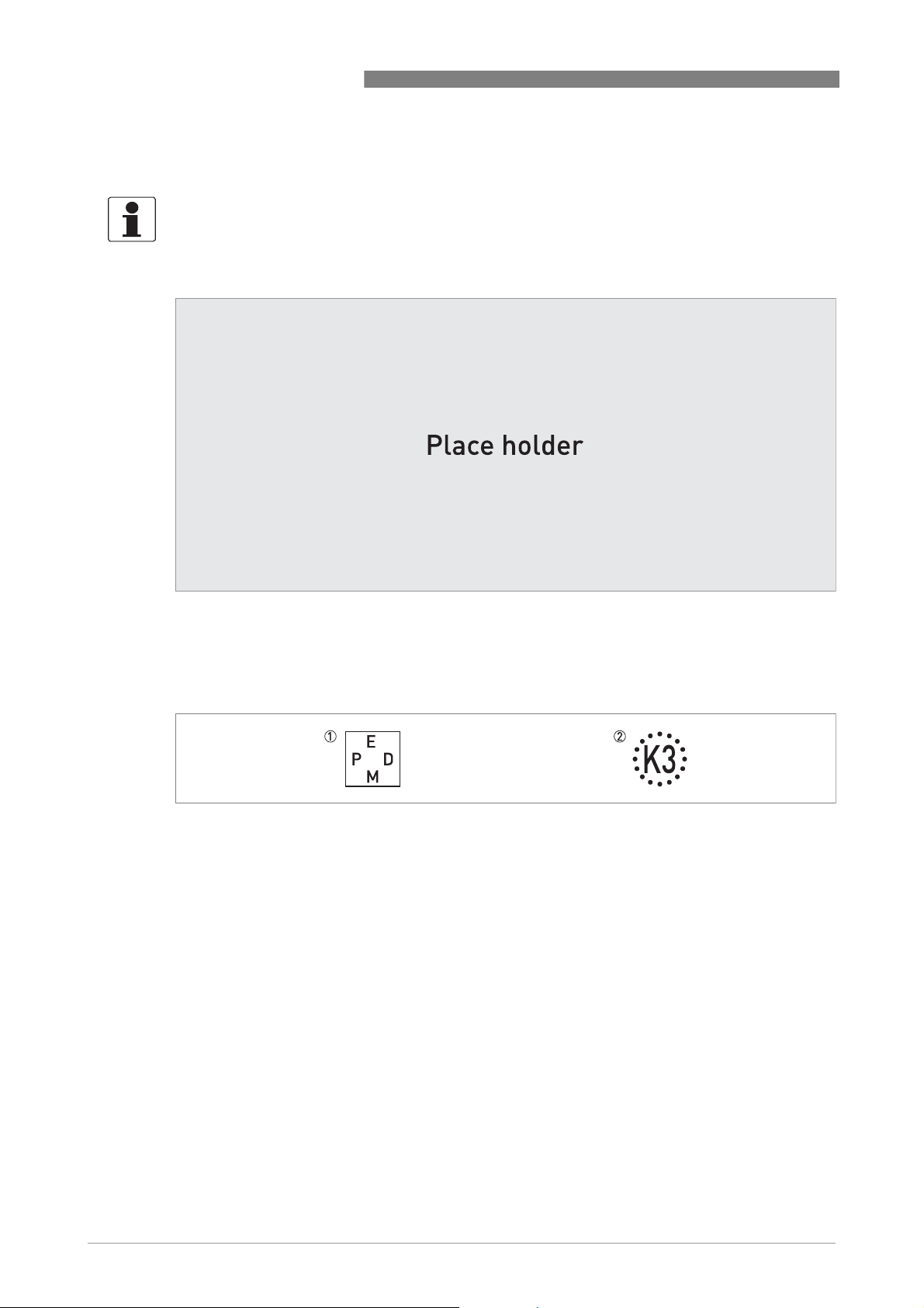
3 Gasket material data - refer to the illustration that follows
Figure 2-4: Symbols for the supplied gasket material (on the side of the process connection)
1 EPDM
2 Kalrez
®
6375
If the device is supplied with an FKM/FPM gasket, there is no symbol on the side of the process
connection.
14
www.krohne.com 09/2014 - 4003537401 - MA OPTIWAVE 1010 R01 en
Page 15

OPTIWAVE 1010
2.4 Nameplates
INFORMATION!
Look at the device nameplate to ensure that the device is delivered according to your order.
Check for the correct supply voltage printed on the nameplate.
2.4.1 Nameplate (example)
DEVICE DESCRIPTION 2
Figure 2-5: Non-Ex nameplate attached to the housing
1 Cable entry size
2 Input / output option
3 Degree of ingress protection (according to EN 60529 / IEC 60529)
4 Customer tag number
5 Date of manufacture
6 Order number
7 Type code (defined in order)
8 Model name and number
9 Company name and address
www.krohne.com09/2014 - 4003537401 - MA OPTIWAVE 1010 R01 en
15
Page 16
3 INSTALLATION
3.1 General notes on installation
INFORMATION!
Inspect the packaging carefully for damages or signs of rough handling. Report damage to the
carrier and to the local office of the manufacturer.
INFORMATION!
Do a check of the packing list to make sure that you have all the elements given in the order.
INFORMATION!
Look at the device nameplate to ensure that the device is delivered according to your order.
Check for the correct supply voltage printed on the nameplate.
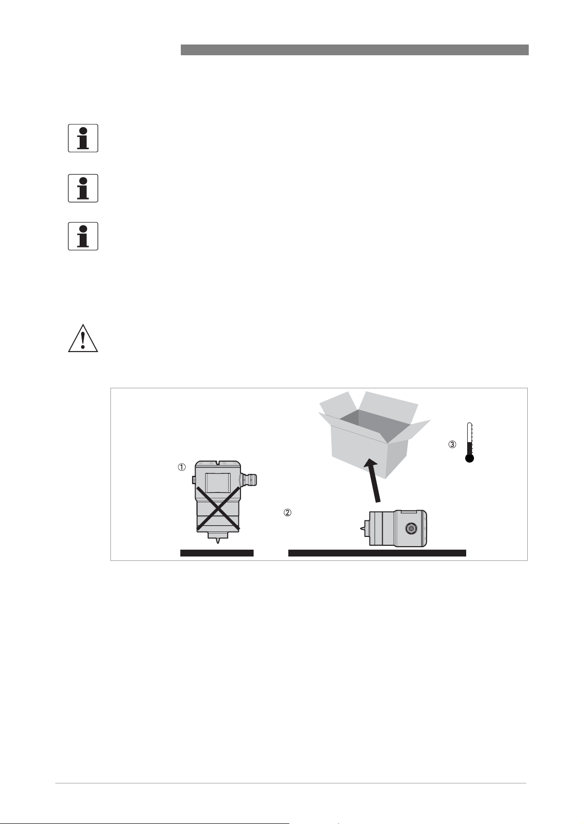
3.2 Storage
WARNING!
Do not keep the device in a vertical position. This will damage the wave guide connection and the
device will not measure correctly.
OPTIWAVE 1010
16
Figure 3-1: Storage conditions
1 When you put the device into storage, do not keep it in a vertical position
2 Put the device on its side. We recommend that you use the packaging in which it was delivered.
3 Storage temperature range: -40...+85°C / -40...+185°F
• Store the device in a dry and dust-free location.
• Store the device in its original packing.
www.krohne.com 09/2014 - 4003537401 - MA OPTIWAVE 1010 R01 en
Page 17
OPTIWAVE 1010
3.3 Transport
WARNING!
•
Depending on the version, the device will weight approx. x...xx kg / xx...xx lb. To carry, use
both hands to lift the device carefully by the converter housing. If necessary, lift the device
with a hoist.
•
When handling the device, avoid hard blows, jolts, impact, etc. to prevent damage.
3.4 Pre-installation requirements
INFORMATION!
Obey the precautions that follow to make sure that the device is correctly installed.
• Make sure that there is sufficient space on all sides.
• Protect the signal converter from direct sunlight.
• Do not subject the signal converter to heavy vibrations.
INSTALLATION 3
3.5 Pressure and temperature ranges
DANGER!
If the ambient temperature is more than +70
device. Use a protective cover or metallic grid to prevent injury.
Figure 3-2: Pressure and temperature ranges
1 Flange temperature
Non-Ex devices: Depends on the device versions (standard, HP and HT/HP versions) and the seal material. Refer to
the table that follows.
Ex devices: see supplementary operating instructions
2 Ambient temperature
Non-Ex devices: -40...+80°C / -40...+176°F
Ex devices: see supplementary operating instructions
3 Process pressure
Depends on the type of antenna and process connection. Refer to the table that follows.
°
C / +158°F, there is a risk of injury if you touch the
www.krohne.com09/2014 - 4003537401 - MA OPTIWAVE 1010 R01 en
17
Page 18

3 INSTALLATION
Aluminium housing for non-Ex and Ex i-approved devices
OPTIWAVE 1010
Version Seal Temperature
extension
Process connection
temperature
Process pressure
[°C] [°F] [barg] [psig]
Standard FKM/FPM with
PEEK
Kalrez® 6375
with PEEK
EPDM with PEEK without -40...+100 -40...+212
HP 1 FKM/FPM with
Metaglas®
Kalrez® 6375
with Metaglas®
EPDM with
Metaglas®
HT or
HT/HP
1 HP = high-pressure version. HT = high-temperature version. HT/HP = high-pressure / high-temperature version.
1
FKM/FPM with
Metaglas®
Kalrez® 6375
with Metaglas®
EPDM with
Metaglas®
without -30...+100 -22...+212 -1...16 -14.5...232
without -20...+100 -4...+212
without -30...+100 -22...+212 -1...40 -14.5...580
without -20...+100 -4...+212
without -40...+100 -40...+212
with -30...+150 -22...+302 -1...40 -14.5...580
with -20...+150 -4...+302
With -40...+120 -40...+248
Stainless steel housing for non-Ex and Ex d-approved devices
Version Seal Temperature
extension
Standard FKM/FPM with
Metaglas®
Kalrez® 6375
with Metaglas®
EPDM with
Metaglas®
without -30...+150 -22...+302 -1...40 -14.5...580
without -20...+150 -4...+302
without -40...+120 -40...+248
For more data on pressure ratings, refer to
Process connection
temperature
[°C] [°F] [barg] [psig]
Pressure ratings
Process pressure
on page 54
18
www.krohne.com 09/2014 - 4003537401 - MA OPTIWAVE 1010 R01 en
Page 19
OPTIWAVE 1010
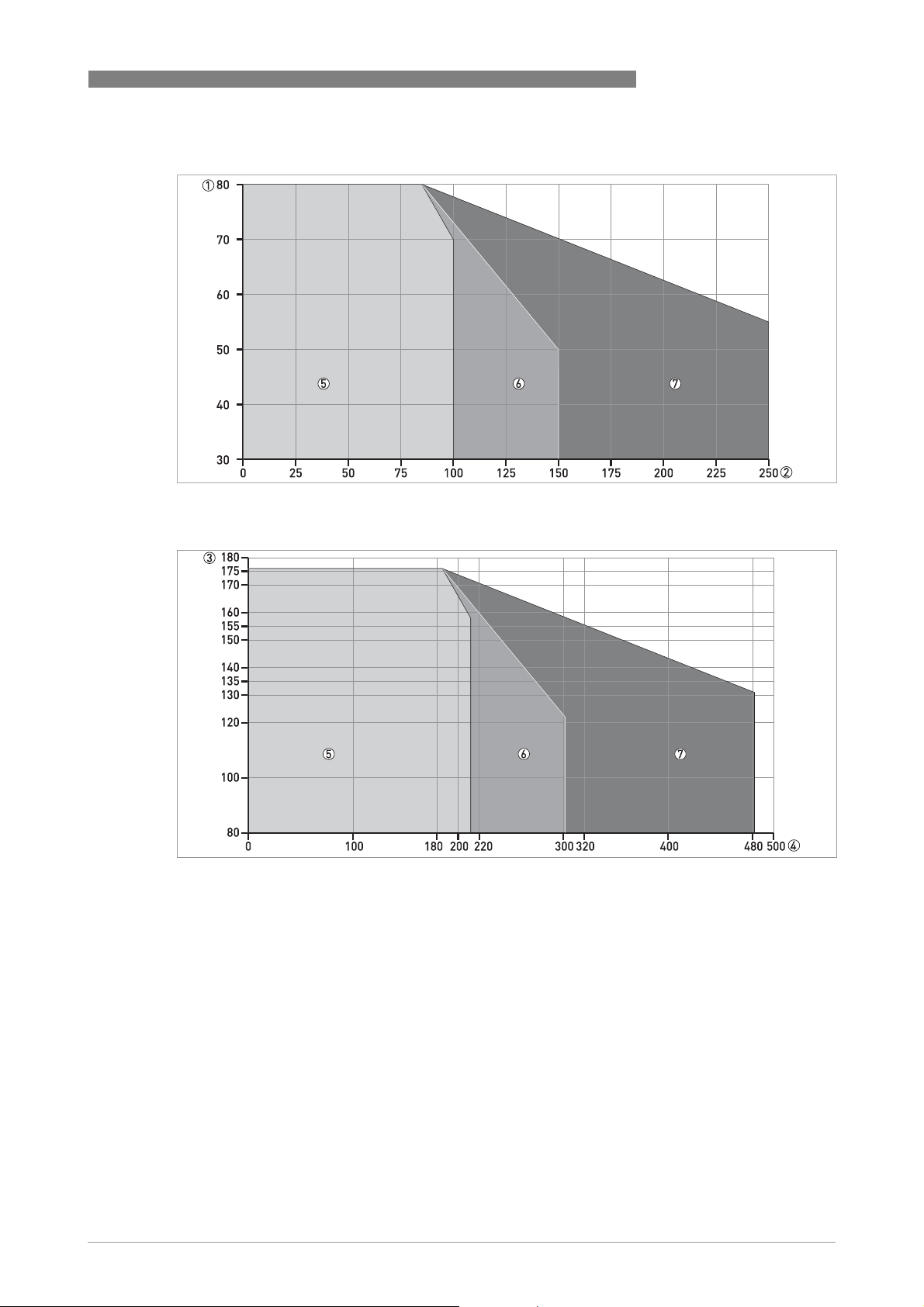
Ambient temperature / flange temperature, flange and threaded connection, in °C
Figure 3-3: Ambient temperature / flange temperature, flange and threaded connection, in °C
INSTALLATION 3
Ambient temperature / flange temperature, flange and threaded connection, in °F
Figure 3-4: Ambient temperature / flange temperature, flange and threaded connection, in °F
1 Maximum ambient temperature, °C
2 Maximum flange temperature, °C
3 Maximum ambient temperature, °F
4 Maximum flange temperature, °F
5 Metallic Horn antennas
There is no change (de-rating) in ambient temperature below 0°C/ 0°F. The process connection
temperature must agree with the temperature limits of the gasket material. For pressure rating
data,.
www.krohne.com09/2014 - 4003537401 - MA OPTIWAVE 1010 R01 en
19
Page 20
3 INSTALLATION
3.6 Recommended mounting position
CAUTION!
Follow these recommendations to make sure that the device measures correctly. They have an
effect on the performance of the device.
CAUTION!
Make sure that the cable glands are aligned with the process connections of the bypass
chamber.
OPTIWAVE 1010
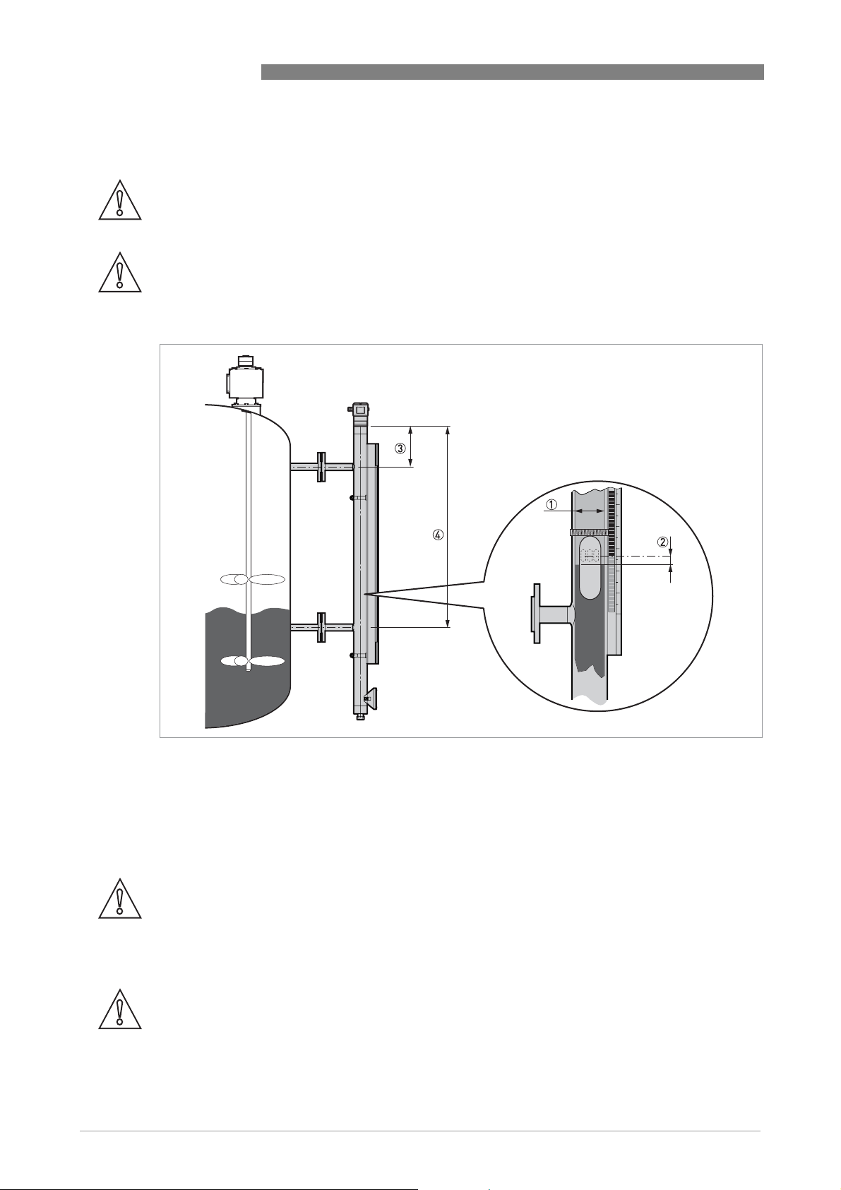
Figure 3-5: Recommended mounting position
1 Internal tube diameter. Min. / Max.: 32...67 mm / 1.26...2.64¨
2 Float offset. Min. / Max.: 0...150 mm / 0...5.91¨
3 Distance to top process connection (bypass chamber). Min. / Max.: 0...800 mm / 0...2.64¨
4 Distance to bottom process connection (bypass chamber). Min. / Max.: 32...67 mm / 1.26...2.64¨
3.7 Mounting restrictions
CAUTION!
Follow these recommendations to make sure that the device measures correctly. They have an
effect on the performance of the device.
We recommend that you prepare the installation when the tank is empty.
CAUTION!
If there are parasitic signals, the device will not measure correctly. Parasitic signals are caused
by sudden changes in bypass chamber diameter in the path of the radar beam.
20
www.krohne.com 09/2014 - 4003537401 - MA OPTIWAVE 1010 R01 en
Page 21
OPTIWAVE 1010
3.8 Stilling wells
Install the device in a metal stilling well if the radar level transmitter is attached to the top of the
tank and not on the top of a magnetic (bypass) level indicator or a bypass chamber.
CAUTION!
If the stilling well has liquid circulation holes, then the tank must be made of metal or reinforced
concrete to prevent radio frequency interference.
INSTALLATION 3
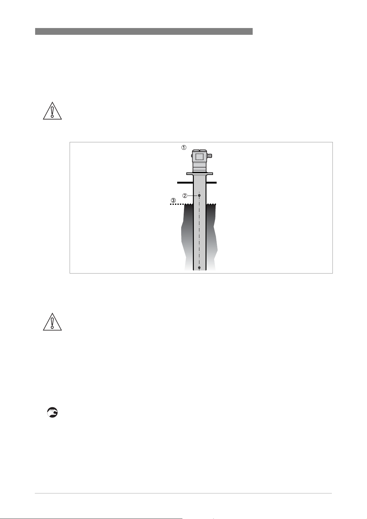
Figure 3-6: Installation recommendations for stilling wells
1 A stilling well solution
2 Air circulation hole
3 Level of the liquid
CAUTION!
Installation requirements
•
The standpipe must be electrically conductive.
•
The standpipe must be straight. There must be no sudden changes in internal diameter
greater than 1 mm / 0.04
•
The standpipe must be vertical.
•
Recommended surface roughness: <±0.1 mm / 0.004¨.
•
Make sure that there are no deposits at the bottom of the standpipe.
•
Make sure that there is liquid in the standpipe.
¨
.
General notes
Installation in tanks containing one liquid and foam
• Drill an air circulation hole (max. Ø10 mm / 0.4¨) in the stilling well above the maximum level.
• Remove the burr from the hole.
www.krohne.com09/2014 - 4003537401 - MA OPTIWAVE 1010 R01 en
21
Page 22

3 INSTALLATION
Installation in tanks containing one liquid or more without foam
• Drill an air circulation hole (max. Ø10 mm / 0.4¨) in the stilling well above the maximum level.
• Drill 1 or more liquid circulation holes in the stilling well (if there is more than 1 liquid in the
tank).
i These holes help the liquid to move freely between the stilling well and the tank.
• Remove the burr from the hole.
3.9 How to attach the weather protection to the device
The device and the weather protection option are supplied disassambled in the same box. You
must attach the weather protection when you install the device.
OPTIWAVE 1010
Figure 3-7: Equipment needed
1 Device
2 Weather protection (option).
3 2 butterfly screws and spring washers. The manufacturer attaches these parts to the device before delivery.
The overall dimensions of the weather protection are.
22
www.krohne.com 09/2014 - 4003537401 - MA OPTIWAVE 1010 R01 en
Page 23
OPTIWAVE 1010
4.1 Safety instructions
DANGER!
All work on the electrical connections may only be carried out with the power disconnected. Take
note of the voltage data on the nameplate!
DANGER!
Observe the national regulations for electrical installations!
DANGER!
For devices used in hazardous areas, additional safety notes apply; please refer to the Ex
documentation.
WARNING!
Observe without fail the local occupational health and safety regulations. Any work done on the
electrical components of the measuring device may only be carried out by properly trained
specialists.
ELECTRICAL CONNECTIONS 4
INFORMATION!
Look at the device nameplate to ensure that the device is delivered according to your order.
Check for the correct supply voltage printed on the nameplate.
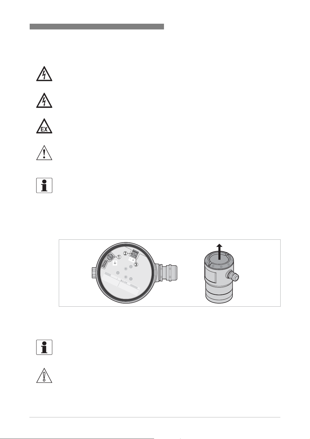
4.2 Electrical installation: 2-wire, loop-powered
Figure 4-1: Terminals for electrical installation
1 Grounding terminal in the housing (if the electrical cable is shielded)
2 Current output -
3 Current output +
INFORMATION!
Electrical power to the output terminal energizes the device. The output terminal is also used for
®
HART
communication.
CAUTION!
Use the applicable electrical cables with the cable glands.
www.krohne.com09/2014 - 4003537401 - MA OPTIWAVE 1010 R01 en
23
Page 24

4 ELECTRICAL CONNECTIONS
4.3 Electrical connection for current output
4.3.1 Non-Ex devices
Figure 4-2: Electrical connections for non-Ex devices
1 Power supply
2 Resistor for HART
3 Optional connection to the grounding terminal
4 Output: 14.5...30 VDC for an output of 22 mA at the terminal
5 Device
®
communication
OPTIWAVE 1010
4.3.2 Devices for hazardous locations
DANGER!
For electrical data for device operation in hazardous locations, refer to the related certificates of
compliance and supplementary instructions (ATEX, IECEx, FM, CSA, ...). You can find this
documentation on the DVD-ROM delivered with the device or it can be downloaded free of charge
from the website (Download Center).
4.4 Protection category
INFORMATION!
The device fulfils all requirements per protection category IP 66/67. It also fulfils all
requirements per NEMA type 4X (housing) and type 6P .
DANGER!
Make sure that the cable gland is watertight.
24
Figure 4-3: How to make the installation agree with protection category IP 67
www.krohne.com 09/2014 - 4003537401 - MA OPTIWAVE 1010 R01 en
Page 25

OPTIWAVE 1010
• Make sure that the gaskets are not damaged.
• Make sure that the electrical cables are not damaged.
• Make sure that the electrical cables agree with the national electrical code.
• The cables are in a loop in front of the device 1 so water does not go into the housing.
• Tighten the cable feedthroughs 2.
• Close unused cable feedthroughs with dummy plugs 3.
4.5 Networks
4.5.1 General information
The device uses the HART® communication protocol. This protocol agrees with the HART®
Communication Foundation standard. The device can be connected point-to-point. It can also
operate in a multi-drop network of up to 15 devices.
The device output is factory-set to communicate point-to-point. To change the communication
mode from point-to-point to multi-drop.
4.5.2 Point-to-point connection
ELECTRICAL CONNECTIONS 4
Figure 4-4: Point-to-point connection (non-Ex)
1 Address of the device (0 for point-to-point connection)
2 4...20 mA + HART
3 Resistor for HART® communication
4 Power supply
5 HART
6 HART
®
converter
®
communication software
®
www.krohne.com09/2014 - 4003537401 - MA OPTIWAVE 1010 R01 en
25
Page 26
4 ELECTRICAL CONNECTIONS
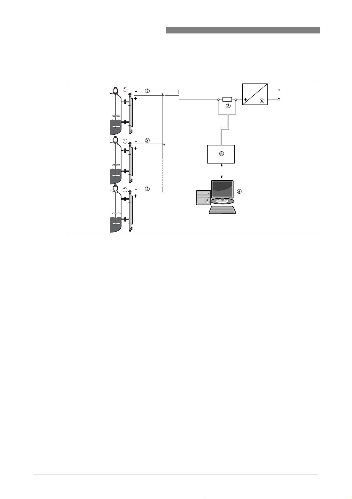
4.5.3 Multi-drop networks
OPTIWAVE 1010
Figure 4-5: Multi-drop network (non-Ex)
1 Address of the device (each device must have a different address in multidrop networks)
2 4mA + HART
3 Resistor for HART® communication
4 Power supply
5 HART
6 HART
®
®
converter
®
communication software
26
www.krohne.com 09/2014 - 4003537401 - MA OPTIWAVE 1010 R01 en
Page 27

OPTIWAVE 1010
5.1 How to start the device
5.1.1 Start-up checklist
Check these points before you energize the device:
• Are all the wetted components (PEEK element, flange and gaskets) resistant to the product in
the tank?
• Does the information on the device nameplate agree with the operating data?
• If the device is supplied with a magnetic (bypass) level indicator: Did you correctly install the
magnetic level indicator adjacent to the tank?
• If the device is supplied without a magnetic (bypass) level indicator: Did you correctly install
the device on top of the bypass chamber or stilling well?
• Do the electrical connections agree with the national electrical codes? Use the applicable
electrical cables with the cable glands.
DANGER!
Before you energize the device, make sure that the supply voltage is correct.
START-UP 5
DANGER!
Make sure that the device and the installation agrees with the requirements of the Ex certificate
of compliance.
5.1.2 How to start the device
• Connect the converter to the power supply.
• Energize the converter.
INFORMATION!
The OPTIWAVE 1010 is set up for your application when it is attached to the top of the BM 26
Advanced Magnetic (Bypass) Level Indicator at the factory. The 0% level (empty) is aligned with
the center of the bottom process connection and the 100% level (full) is aligned with the center of
the top process connection. You can use the HART communication protocol to change these
parameters.
5.2 Operating concept
You can read measurements and configure the device with:
• A connection to a system or PC with PACTware™. You can download the Device Type
Manager (DTM) file from the website. It is also supplied on the DVD-ROM delivered with the
device.
• A connection to a system or PC with AMS™. You can download the Device Description (DD)
file from the website. It is also supplied on the DVD-ROM delivered with the device.
• A connection to a HART
file from the website. It is also supplied on the DVD-ROM delivered with the device.
®
Field Communicator. You can download the Device Description (DD)
For more data about how to use the DTM in PACTware,. For more data about the menu tree for
the Basic-DD, AMS and PDM,.
www.krohne.com09/2014 - 4003537401 - MA OPTIWAVE 1010 R01 en
27
Page 28

5 START-UP
5.3 Remote communication with PACTware™
5.3.1 General notes
PACTware™ displays measurement information clearly on a computer (PC) and lets you
configure the device from a remote location. It is an Open Source, open configuration software
for all field devices. It uses Field Device Tool (FDT) technology. FDT is a communication standard
for sending information between the system and the field device. This standard agrees with
IEC 62453. Field devices are easily integrated. Installation is supported by a user-friendly
Wizard.
OPTIWAVE 1010
Figure 5-1: Start page for PACTware™
5.3.2 Software installation
Equipment needed
• A computer
• One of these two solutions: 1 the DVD-ROM delivered with the device or 2 a high-speed
Internet connection
• A web browser, if it is necessary to download files from the Internet
Software needed
• Microsoft® .NET Framework 1.1 or a later version
• PACTware™ 4.0 or a later version
• Device Type Manager (DTM) for the OPTIWAVE 1010 radar level transmitter
This software is supplied on the DVD-ROM delivered with the device. It can also be downloaded
from the “Download center: Software” web page on the manufacturer’s website.
28
www.krohne.com 09/2014 - 4003537401 - MA OPTIWAVE 1010 R01 en
Page 29

OPTIWAVE 1010
Installation procedure
1 Install Microsoft® .NET Framework 1.1.
2 Install PACTware™ 4.0 or later version.
3 Install the OPTIWAVE 1010 DTM on your workstation or your portable computer. Follow the
instructions in the Installation wizard.
4 Plug the HART modem into your computer (Serial or USB HART® modem). If you are using a
USB® HART modem, you must install the Driver for the USB HART® modem first. Make sure
that the location of the port for the HART® modem is clearly identified.
5 Start the PACTware™ program.
i End of the procedure.
5.4 Remote communication with the AMS™ Device Manager
The AMS™ Device Manager is an industrial Plant Asset Management (PAM) software tool. Its
role is to:
• Store configuration information for each device.
• Support HART® devices.
• Store and read process data.
• Store and read diagnostic status information.
• Help plan preventive maintenance to reduce a plant's downtime to a minimum.
START-UP 5
The DD file is given on the DVD-ROM supplied with the device. You can also download it from our
website.
www.krohne.com09/2014 - 4003537401 - MA OPTIWAVE 1010 R01 en
29
Page 30

6 OPERATION
6.1 Software configuration
6.1.1 General notes
How to configure the software for device communication.
Before the program can send data to and receive data from the device, it is necessary to add
elements to a project structure. The project structure is built in the PACTware™ Project pane.
The Project pane is on the left side of the window.
This procedure will open the communication port, but does not start the communication with the
device.
6.1.2 Procedure
INFORMATION!
This procedure will open the communication port, but DOES NOT start the communication with
the device.
OPTIWAVE 1010
• HOST PC is shown in the Project pane. Go to the main toolbar and click on the View menu
button. Click on "Device catalog F3" to open the Device Catalog pane.
• Double click on “HART Communication” in the Device Catalog pane. The "COM4" element is
added below "HOST PC” in the project structure.
• Click on "OK" to save changes or "Cancel" to cancel the new configuration.
• Double click on the "OPTIWAVE 1010" item in the Device Catalog pane. This step will add the
device DTM to the project structure in the Project pane.
i The software is correctly configured for device communication, but the port is not open and
the device cannot communicate with the software at this time.
• (a) Double click on the "OPTIWAVE 1010" element in the project structure (Project pane), or (b)
Right click on "OPTIWAVE 1010" element in the project structure (Project pane) and select
"Parameter" in the drop-down list box.
i This step will open the OPTIWAVE 1010 Parameter (configuration) window.
• Right click on the "OPTIWAVE 1010" element in the Project pane and select "Connect" in the
drop-down list box.
i The software is correctly configured for device communication and the port is open, but the
device cannot communicate with the software at this time. End of the procedure.
30
www.krohne.com 09/2014 - 4003537401 - MA OPTIWAVE 1010 R01 en
Page 31

OPTIWAVE 1010
6.2 How to load settings from the device to PACTware™
There are 3 alternative procedures.
Procedure 1: Click on "Load from Device" in the Device menu
OPERATION 6
Figure 6-1: Click on "Load from Device" in the Device menu
• Click on the Device button in the main toolbar.
• Select "Load from device" from the list.
i End of the procedure.
Procedure 2: Click on the "Load from Device" icon in the main toolbar
Figure 6-2: Click on the "Load from Device" icon in the main toolbar
• Click on this icon (you can find this icon below the main toolbar).
i End of the procedure.
www.krohne.com09/2014 - 4003537401 - MA OPTIWAVE 1010 R01 en
31
Page 32

6 OPERATION
Procedure 3: Right click on the "OPTIWAVE 1010" element in the Project pane
OPTIWAVE 1010
Figure 6-3: Right click on the "OPTIWAVE 1010" element in the Project pane
• Right click on the "OPTIWAVE 1010" element in the Project pane.
• Select "Load from device" from the list.
i End of the procedure.
6.3 Menu overview
• Login/Logout
• Import/Export
• Basic parameters
• Signal output
• Application
• HART
• Service
• DTM settings
The service menu is password locked. This menu is for qualified service personnel only.
32
www.krohne.com 09/2014 - 4003537401 - MA OPTIWAVE 1010 R01 en
Page 33

OPTIWAVE 1010
6.4 Device settings
6.4.1 Supervisor access rights
It is necessary to have "Supervisor" access rights to change device settings.
The device configuration is locked (write protected). To unlock the configuration and change
device settings, you need to log in as a "Supervisor". If you do not log in as a Supervisor, you can
only read the device configuration.
Procedure
• (a) Double click on the "OPTIWAVE 1010" element in the project structure (Project pane) or (b)
Right click on "OPTIWAVE 1010" element in the project structure (Project pane) and select
"Parameter" in the drop-down list box.
• Click on the Log In / Log Out menu and select "Supervisor".
• Enter the password (the default password is 123412).
• The device configuration is unlocked. Change the device settings. Refer to the handbook for
more data on menu items and their parameters.
i End of the procedure.
OPERATION 6
6.4.2 How to change device settings
CAUTION!
If you change the device settings, the DTM saves the device configuration in the computer
database. It does not send the changes to the device. For morea data about how to store the new
settings to the device,.
At the bottom right of the window there are 3 buttons. These buttons are used only to update the
computer database. If you click on "OK" or "Apply", no data is sent to the device. This function
obeys FDT guidelines for certification of the DTM.
Figure 6-4: Use "OK" or "Apply" to update the computer database
When you change the value of a menu item, a pencil symbol is shown adjacent to the changed
value:
www.krohne.com09/2014 - 4003537401 - MA OPTIWAVE 1010 R01 en
33
Page 34

6 OPERATION
Figure 6-5: Pencil symbol: changed value
If the value is too large or too small, a red exclamation mark is shown adjacent to the incorrect
value:
OPTIWAVE 1010
Figure 6-6: Exclamation mark (!): the value is too large or too small
6.4.3 Data about menu items and parameters (online Help)
More data is available for menu items in the Basic Parameters, Signal output, Application and
HART menus.
Put the mouse pointer on a box in the menu. A tooltip gives a description of the menu item.
34
Figure 6-7: Data about parameters – part1: tooltip
www.krohne.com 09/2014 - 4003537401 - MA OPTIWAVE 1010 R01 en
Page 35

OPTIWAVE 1010
Right click on the text for data about parameters. A tooltip shows the default value, data set
value (new value), minimum value and maximum value of the menu item.
Figure 6-8: Data about parameters – part 2: values
6.4.4 Basic parameters
OPERATION 6
Use the "basic parameters" menu to specifiy the basic configuration of the device. The
supervisor can specify the minimum distance (NO), maximum distance (ND), float offset (FO) and
tube internal diameter (PD).
For more data about float offset,.
Figure 6-9: Basic parameters menu
www.krohne.com09/2014 - 4003537401 - MA OPTIWAVE 1010 R01 en
35
Page 36

6 OPERATION
6.4.5 Signal output
Use the "signal output" pane to specifiy the type of data that the current output must supply. The
supervisor can set the measurement function (e.g. level, distance etc.), the output range, the
error delay, minimum distance (NO) and maximum distance (ND).
INFORMATION!
Minimum distance (NO) and maximum distance (ND) is also given in the "basic parameter"
menu.
OPTIWAVE 1010
Figure 6-10: Signal output menu
6.4.6 Import / export
You can use the import /export function to do 2 procedures:
• Import device configuration data in a CFG file. You can then transmit the data to the device
(Store to device).
• Export device configuration data (parameters etc.) in a CFG file. You can use this data for the
configuration of other devices.
INFORMATION!
You can save measurement data in a DAT file when you use the "Record" function in the Analysis
Values menu. For more data, refer to the "Analysis values" section.
36
www.krohne.com 09/2014 - 4003537401 - MA OPTIWAVE 1010 R01 en
Page 37

OPTIWAVE 1010
Figure 6-11: Import / export function
OPERATION 6
Export device configuration data
• Click on "Import / Export" in the menu list.
• Click on the Export button.
• Click on the >> button.
• Enter a file name and click on the Save button.
• Enter comments and supplementary data in the "File Comment" and "...comment for export
file" boxes.
• Click on the "tick" button to complete the procedure.
Import device configuration data
• Click on "Import / Export" in the menu list.
• Click on the Import button.
• Click on the >> button.
• Find the file and click on the Open button.
• Enter comments and supplementary data in the "File Comment" and "...comment for export
file" boxes.
• Click on the "tick" button to complete the procedure.
6.4.7 Application
Use the "application" menu to specifiy how the device monitors level. The supervisor can give the
time constant, maximum tracing speed, multiple reflections and minimum peak to identify the
correct signal and follow it as level changes.
Figure 6-12: Application menu
www.krohne.com09/2014 - 4003537401 - MA OPTIWAVE 1010 R01 en
37
Page 38
6 OPERATION
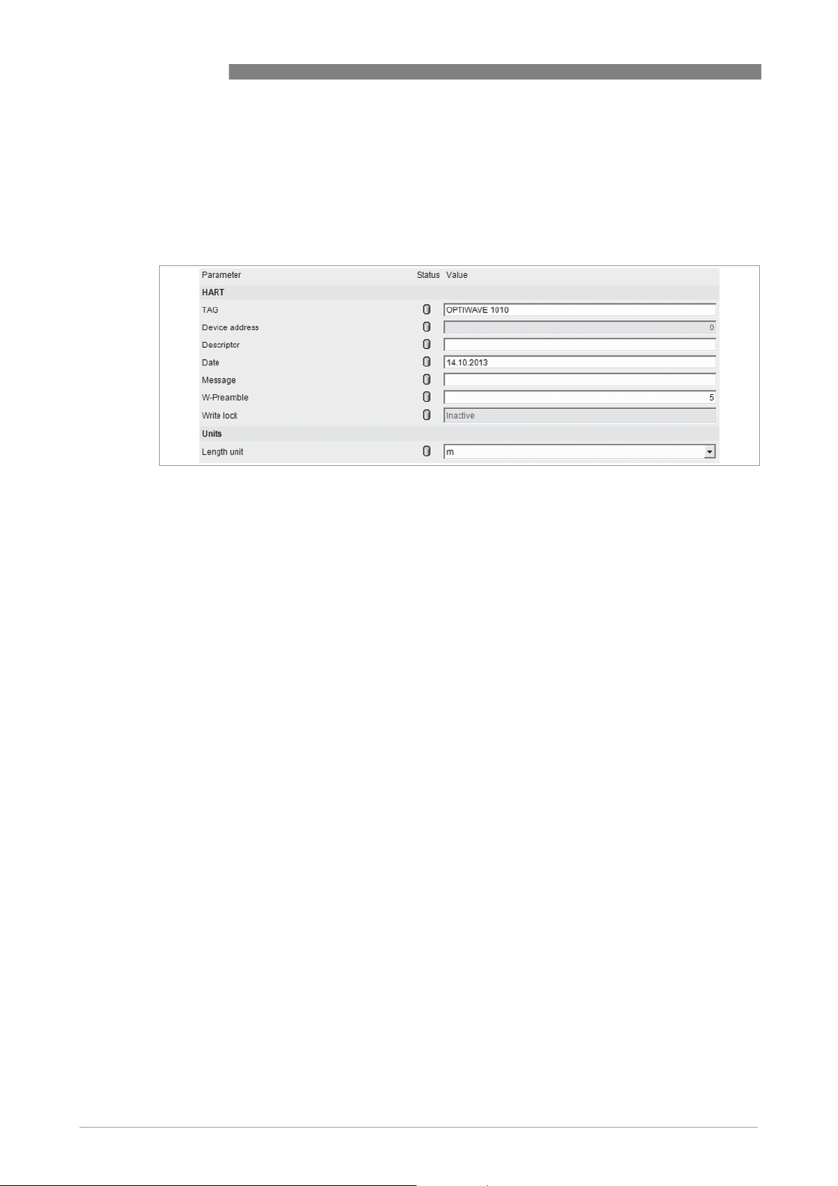
6.4.8 HART
This menu lists all the data necessary for use in a HART® network. The supervisor can specify
the tag name, device address, descriptor, date, message, W-Preamble, length unit and use a
write lock to prevent changes to the data.
Figure 6-13: HART menu
OPTIWAVE 1010
38
www.krohne.com 09/2014 - 4003537401 - MA OPTIWAVE 1010 R01 en
Page 39

OPTIWAVE 1010
6.5 Status and error messages
6.5.1 Device status
Error data is given if you use PACTware™ software with the appropriate DTM on a PC. The
sofware will show a symbol on the bottom left of the window if one or more error conditions are
found. This data agrees with NAMUR Recommendation NE 107 (Self-Monitoring and Diagnosis of
Field Devices) and VDI/VDE 2650.
Types of error message
OPERATION 6
NE 107 status Type of
Description
error
Failure Error If an error message is shown on the diagnostics screen in the DTM, the current
Out of specification Warning If a warning message is shown, there is no effect on the current output value.
Maintenance
NE 107
symbol
NE 107
Status
output goes to the error signal value set in "Signal output", menu item "range
current output".
Description Error type Possible errors
shown
Failure The device does not operate
Function
check
Out of
specification
Maintenance The device does not operate
Information This status message is shown at
correctly. The fault message
stays on.
The device operates correctly,
but the measured value is
incorrect. This fault message is
only temporary. This symbol is
shown when the user configures
the device with the DTM or a
HART® Communicator.
It is possible that the measured
value is unstable if the operating
conditions do not agree with the
device specification.
correctly because of bad
environmental conditions (e.g.
build-up on the antenna). The
measured value is correct, but
maintenance is neccessary a
short time after this symbol is
shown.
the same time as the error "no
measuring value".
Hardware error Microwave error
Hardware error EEPROM error (Config.)
Hardware error EEPROM error (HART)
Hardware error Output current calibration not valid
Error No signal
Error No measuring value
Error Hardware error
Error Current output set to error
– –
Warning Signal weak
Warning Signal strong
Warning Spectrum quality bad
Warning Measurement old
Warning Sweep timing error
Warning CPLD revision mismatch
Warning Capacitor voltage low
Information Peak lost in tank bottom
Information Peak lost in blocking distance
For data on errors, refer to
Error handling
www.krohne.com09/2014 - 4003537401 - MA OPTIWAVE 1010 R01 en
on page 40.
39
Page 40

6 OPERATION
6.5.2 Error handling
Figure 6-14: Error record screen in the DTM for PACTware™
Description of errors and corrective actions
Error Message Cause Corrective action
OPTIWAVE 1010
Failure (NE 107 status signal)
Microwave error The device's hardware is defective. Replace the signal converter.For more data, refer to
EEPROM error
(Config.)
EEPROM error
(HART)
Output current
calibration not
valid
No signal
No measuring
value
Hardware error
Current output set
to error
Service warranty
on page 44.
Out of specification (NE 107 status signal)
Signal weak The signal amplitude is less than the
Signal strong This error can occur if there is a large
Spectrum quality
bad
average value. This can occur if the
liquid is agitated or if there is foam in the
tank. If this error occurs frequently, the
device will possibly show the "No
measuring value" error message. 1
change in signal amplitude. 1
The quality of the spectrum is poor. If
this message is temporarily shown, this
will not affect the performance of the
device. If this message is continuously
shown, the measured values can be
incorrect. The error message
"Measurement old" will then be shown.
Possible causes are foam, vortices,
turbulent product surface and internal
tank elements.
If this error occurs frequently, it is possible that you
must install a float with a radar target (if there is no
float supplied with the device).
No corrective action is necessary.
Do a check of the device, tank and the process. Change
the device settings. If necessary, contact the supplier.
40
www.krohne.com 09/2014 - 4003537401 - MA OPTIWAVE 1010 R01 en
Page 41

OPTIWAVE 1010
OPERATION 6
Error Message Cause Corrective action
Measurement old This is a temporary error message. If the
device cannot get a measurement in this
time limit, the displayed measurement
is no longer correct. The voltage is
possibly too low. If the device continues
to show the message "Spectrum quality
bad", then this message is also shown.
Do a check of the voltage at the device terminals. Refer
also to the error message "Spectrum quality bad".
Maintenance (NE 107 status signal)
Sweep timing error
CPLD revision
mismatch
Capacitor voltage
low
Information
Peak lost in tank
bottom
Peak lost in
blocking distance
Device reset The device detected an internal error
Current Output
Drift
Temperature out
of range
Converter memory
failure
Converter Voltage
failure
Internal
Communication
Overfill The level is in the blocking distance.
Peak Lost (Level
Lost)
Sensor no Signal The device's hardware is defective. Replace the signal converter.
The level is in the blocking distance.
There is a risk that the product will
overflow and/or cover the device.
(watchdog timer issue).
The current output is not calibrated. Speak to the supplier to get the calibration procedure.
Hardware error. Replace the device.
The ambient temperature is outside the
given range. This can cause loss or
corruption of data.
The device's hardware is defective. Replace the signal converter.
The device's hardware is defective. Replace the signal converter.
The device's hardware or software is
defective. The converter cannot transmit
signals to or receive signals from the
antenna electronics.
There is a risk that the product will
overflow and/or cover the antenna.
Remove some of the product until the level is below the
blocking distance.
Record the data that is in menu item 2.2.2 DIAGNOSTIC
(Configuration mode / Supervisor menu). Speak to the
supplier.
Measure the ambient temperature. De-energize the
device until the ambient temperature is back in the
given range. If the temperature does not stay in the
correct range, make sure that there is insulation
around the signal converter. If this error occurs 2
times, replace the device.
De-energize the device. Make sure that the signal
cable engages in the terminal and the screw
connection is tight. Energize the device. If the problem
continues, replace the signal converter.
Use a different procedure to measure the level in the
tank. Remove some of the product until the level is
below the blocking distance.
If a viscous product touched the antenna:
• remove the device and clean the antenna, or
• If the device has a purging option, use the purging
system to clean the antenna.
The signal peak is not found within the
measuring window that filters the
signals received by the antenna. The
measurement is not correct. The device
will automatically increase this window
to find the correct signal.
Do a check of the device, tank and the process.
Reconfigure the device and record a new empty
spectrum. Follow the instructions on page . If
necessary, speak to the supplier.
www.krohne.com09/2014 - 4003537401 - MA OPTIWAVE 1010 R01 en
41
Page 42

6 OPERATION
Error Message Cause Corrective action
OPTIWAVE 1010
Sensor Microwave
failure
Sensor Memory
failure
Sensor Voltage
failure
Sensor Not
compatible
The device's hardware is defective. Replace the signal converter.
The device's hardware is defective. Replace the signal converter.
The device's hardware is defective. Do a check of the power supply at the device terminals.
The software version of the sensor is not
compatible with the software version of
the signal converter.
Defective wiring.
Out of specification (NE 107 status signal)
Temperature Out
of Range
Overfill The level is in the blocking distance.
Peak Lost The signal peak is not found within the
The ambient temperature is outside the
given range. This can cause loss or
corruption of data.
There is a risk that the product will
overflow and/or cover the device.
measuring window that filters the
signals received by the antenna. The
measurement is not correct. The device
will automatically increase this window
to find the correct signal.
Make sure that voltage values are in the specified
limits in menu item 2.2.2 DIAGNOSTIC (Configuration
mode / Supervisor menu). If the voltage is correct,
replace the signal converter.
Go to menu 1.1.0 IDENT. in Configuration mode.
Record the version numbers of the device software
given in menu items 1.1.2, 1.1.3 and 1.1.4. Give this
data to the supplier.
Measure the ambient temperature. De-energize the
device until the ambient temperature is back in the
given range. If the temperature does not stay in the
correct range, make sure that there is insulation
around the signal converter. If this error occurs 2
times, replace the device.
Remove some of the product until the level is below the
blocking distance.
Do a check of the device, tank and the process and
make sure that the data agrees with the device
configuration. If necessary, record a new empty
spectrum. Follow the instructions on page . If
necessary, speak to the supplier.
Maintenance (NE 107 status signal)
Empty Spectrum
Invalid
Signal Weak The signal amplitude is less than the
Signal Strong This error can occur if there is a large
Bad Measurement
Quality
Temperature
<-35°C/ -31°F
The empty spectrum stored in the device
does not agree with the installation. If
you change the device configuration
(tank height etc.), this message will be
shown. The recorded empty spectrum
will not be used by the device while this
error message is shown.
average value. This can occur if the
liquid is agitated or if there is foam in the
tank. If this error occurs frequently, the
device will possibly show the "Peak Lost
(Level Lost)" error message. 1
change in signal amplitude. 1
The measurement is incorrect and
continues to be incorrect after more
than 10 s. This error can occur if the
tank contents are immediately below the
antenna. 1
The process connection or the ambient
temperaure is less than -35°C/ -31°F.
This temperature is near to the
minimum limit for device operation.
1
Record a new empty spectrum. Follow the instructions
on page .
If this error occurs frequently, it is possible that you
must install the device in a stilling well or use a
different antenna type.
No corrective action is necessary.
Record the process with the PACTware™ software tool
to find the cause of the problem. If necessary, speak to
the supplier.
Measure the ambient temperature. De-energize the
device until the ambient temperature is back in the
given range. If the temperature does not stay in the
correct range, make sure that there is insulation
1
around the signal converter.
42
www.krohne.com 09/2014 - 4003537401 - MA OPTIWAVE 1010 R01 en
Page 43

OPTIWAVE 1010
OPERATION 6
Error Message Cause Corrective action
Temperature
>+75°C / +167°F
1 This error message does not have an effect on the current output signal
The ambient temperaure is more than
+75°C / +167°F. This temperature is near
to the maximum limit for device
operation. 1
Measure the ambient temperature. De-energize the
device until the ambient temperature is back in the
given range. If the temperature does not stay in the
correct range, make sure that there is insulation
around the signal converter.
www.krohne.com09/2014 - 4003537401 - MA OPTIWAVE 1010 R01 en
43
Page 44

7 SERVICE
7.1 Periodic maintenance
No maintenance is necessary.
7.2 Service warranty
WARNING!
Only approved personnel can do an inspection of the device and repairs. If you find a problem,
send the device back to the supplier for inspection and/or repairs.
INFORMATION!
The converter housing (compact or remote version) can be detached from the process
connection assembly under process conditions.
Servicing by the customer is limited by warranty to:
• Device with a flanged process connection: The removal and installation of the device. For
more data.
• Device with a welded process connection: The removal and installation of the circuit boards.
For more data.
OPTIWAVE 1010
For more data on how to prepare the device before you send it back to the supplier, refer to
Returning the device to the manufacturer
7.3 Spare parts availability
The manufacturer adheres to the basic principle that functionally adequate spare parts for each
device or each important accessory part will be kept available for a period of 3 years after
delivery of the last production run for the device.
This regulation only applies to spare parts which are subject to wear and tear under normal
operating conditions.
7.4 Availability of services
The manufacturer offers a range of services to support the customer after expiration of the
warranty. These include repair, maintenance, technical support and training.
INFORMATION!
For more precise information, please contact your local sales office.
on page 45.
44
www.krohne.com 09/2014 - 4003537401 - MA OPTIWAVE 1010 R01 en
Page 45

OPTIWAVE 1010
7.5 Returning the device to the manufacturer
7.5.1 General information
This device has been carefully manufactured and tested. If installed and operated in accordance
with these operating instructions, it will rarely present any problems.
CAUTION!
Should you nevertheless need to return a device for inspection or repair, please pay strict
attention to the following points:
•
Due to statutory regulations on environmental protection and safeguarding the health and
safety of our personnel, manufacturer may only handle, test and repair returned devices that
have been in contact with products without risk to personnel and environment.
•
This means that the manufacturer can only service this device if it is accompanied by the
following certificate (see next section) confirming that the device is safe to handle.
CAUTION!
If the device has been operated with toxic, caustic, flammable or water-endangering products,
you are kindly requested:
•
to check and ensure, if necessary by rinsing or neutralising, that all cavities are free from
such dangerous substances,
•
to enclose a certificate with the device confirming that is safe to handle and stating the
product used.
SERVICE 7
www.krohne.com09/2014 - 4003537401 - MA OPTIWAVE 1010 R01 en
45
Page 46

7 SERVICE
7.5.2 Form (for copying) to accompany a returned device
Company: Address:
Department: Name:
Tel. no.: Fax no.:
Manufacturer's order no. or serial no.:
The device has been operated with the following medium:
OPTIWAVE 1010
This medium is: radioactive
water-hazardous
toxic
caustic
flammable
We checked that all cavities in the device are free from such
substances.
We have flushed out and neutralized all cavities in the
device.
We hereby confirm that there is no risk to persons or the environment through any residual media
contained in the device when it is returned.
Date: Signature:
Stamp:
7.6 Disposal
CAUTION!
Disposal must be carried out in accordance with legislation applicable in your country.
46
www.krohne.com 09/2014 - 4003537401 - MA OPTIWAVE 1010 R01 en
Page 47
OPTIWAVE 1010
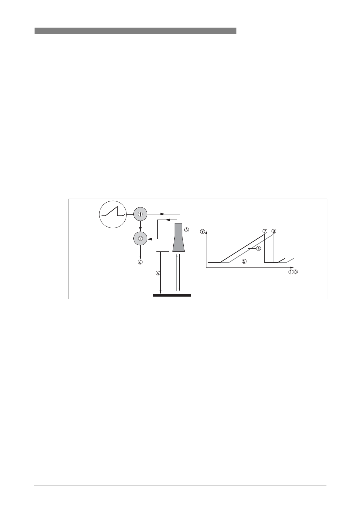
8.1 Measuring principle
A radar signal is emitted via an antenna, reflected from the product surface and received after a
time t. The radar principle used is FMCW (Frequency Modulated Continuous Wave).
The FMCW-radar transmits a high frequency signal whose frequency increases linearly during
the measurement phase (called the frequency sweep). The signal is emitted, reflected on the
measuring surface and received with a time delay, t. Delay time, t=2d/c, where d is the distance
to the product surface and c is the speed of light in the gas above the product.
For further signal processing the difference Δf is calculated from the actual transmitted
frequency and the received frequency. The difference is directly proportional to the distance. A
large frequency difference corresponds to a large distance and vice versa. The frequency
difference Δf is transformed via a Fourier transformation (FFT) into a frequency spectrum and
then the distance is calculated from the spectrum. The level results from the difference between
tank height and measuring distance.
TECHNICAL DATA 8
Figure 8-1: Measuring principle of FMCW radar
1 Transmitter
2 Mixer
3 Antenna
4 Distance to product surface, where change in frequency is proportional to distance
5 Differential time delay, Δt
6 Differential frequency, Δf
7 Frequency transmitted
8 Frequency received
9 Frequency
10 Time
www.krohne.com09/2014 - 4003537401 - MA OPTIWAVE 1010 R01 en
47
Page 48

8 TECHNICAL DATA
OPTIWAVE 1010
8.2 Technical data
INFORMATION!
•
The following data is provided for general applications. If you require data that is more
relevant to your specific application, please contact us or your local sales office.
•
Additional information (certificates, special tools, software,...) and complete product
documentation can be downloaded free of charge from the website (Download Center).
Measuring system
Measuring principle 2-wire loop-powered level transmitter; C-band (6 GHz) FMCW radar
Application range Level measurement of clean liquids
Primary measured value Distance and reflection
Secondary measured value Level and volume
Design
Construction The measurement system consists of a wave guide connection and a signal
Options Weather protection
Measuring range 0...5.3 m / 0...17.4 ft (max. 8 m / 26.2 ft on request)
Top dead zone Minimum value: 300 mm / 11.8¨ from the process connection
User interface
User interface PACTware™
converter
Measuring accuracy
Repeatability ±1mm/ ±0.04¨
Accuracy ±10 mm / ±0.4¨
Reference conditions acc. to EN 61298-1
Temperature +15...+25°C / +59...+77°F
Pressure 1013 mbara ±50 mbar / 14.69 psia ±0.73 psi
Relative air humidity 60% ±15%
Target Metal plate in an anechoic chamber
48
www.krohne.com 09/2014 - 4003537401 - MA OPTIWAVE 1010 R01 en
Page 49

OPTIWAVE 1010
TECHNICAL DATA 8
Operating conditions
Temperature
Ambient temperature -40…+80°C/ -40…+176°F
Storage temperature -40…+85°C/ -40…+185°F
Process connection temperature
(higher temperature on request)
Pressure
Process pressure Standard (PEEK): -1…16 barg / -14.5…232 psig. For more data, refer to
Other conditions
Dielectric constant (εr) ≥1.8
Ingress protection IEC 60529: IP 66/67
Maximum rate of change 3 m/min / 9.8 ft/min
Ex: see supplementary operating instructions or approval certificates
Standard:
with a Kalrez® 6375 gasket: -20...+100°C / -4...+212°F
with a FKM/FPM gasket: -30...+100°C / -22...+212°F
with a EPDM gasket: -40...+100°C / -40...+212°F 1
High temperature version (HT) with Metaglas® process seal:
with a Kalrez® 6375 gasket: -20...+150°C / -4...+302°F
with a FKM/FPM gasket: -30...+150°C / -22...+212°F
with a EPDM gasket: -40...+130°C / -40...+266°Ft 2
The process connection temperature must agree with the temperature limits of the
gasket material.
Ex: see supplementary operating instructions or approval certificates
ratings
on page 54.
With Metaglas®: -1…40 barg / -14.5…580 psig. For more data, refer to
ratings
on page 54.
NEMA 250: NEMA type 4X (housing) and type 6P (antenna)
Pressure
Pressure
Installation conditions
Pipe internal diameter 3 Standard: Ø42.2
Option: Ø60.3
Dimensions and weights For dimensions and weights data, refer to
Dimensions and weights
on page 55.
Materials
Housing Standard: Polyester-coated aluminium
Option: Stainless steel (1.4404 / 316L)
Wetted materials Standard: Stainless steel (1.4404 / 316L) wave guide connection with a FKM/FPM,
Feedthrough Standard: PEEK process seal with O-ring gasket
Cable gland Standard: none
Weather protection (Option) Stainless steel (1.4404 / 316L)
EPDM or Kalrez® 6375 O-ring gasket
Option: Hastelloy® C-22® (2.4602) wave guide connection with a FKM/FPM, EPDM
or Kalrez® 6375 O-ring gasket
Option (high-temperature version): Metaglas® process seal with O-ring gasket
Options: Plastic (Non-Ex: black, Ex i-approved: blue); nickel-plated brass; stainless
steel
www.krohne.com09/2014 - 4003537401 - MA OPTIWAVE 1010 R01 en
49
Page 50

8 TECHNICAL DATA
OPTIWAVE 1010
Process connections
Welded version
Pipe sizes Stainless steel (1.4404 / 316L): Ø42.4×2; Ø60.3×2; Ø60.3×2.77; Ø60.3×3.9
Hastelloy® C-22® (2.4602) : Ø42.4×2; Ø60.3×2; Ø60.3×2.77; Ø60.3×3.9
Flange version
EN 1092-1 DN40…80 (Form B1, B2, C, D, E or F) in PN16 / 40; others are available on request
ASME B16.5 1½...3¨ (RF or FF) in 150 lb / 300 lb; others are available on request
JIS 40...80A in 10K
Electrical connections
Power supply 14.5…30 VDC; min./max. value for an output of 22 mA at the terminal
Maximum current 22 mA
Current output load RL [Ω] ≤ ((U
voltage
Cable entry Standard: M20×1.5; Option: ½ NPT
Cable gland Standard: none
Options: M20×1.5 (cable diameter: 6...10 mm / 0.2...0.39¨); others are available on
request
Cable entry capacity (terminal) 0.5…2.5 mm²
-14.5 V)/22 mA). For more data, refer to
ext
on page 53.
Minimum power supply
Input and output
Current output / HART®
Output signal
Resolution ±3 µA
Temperature drift Typically 50 ppm/K (150 ppm/K maximum)
Digital temperature drift Max. ±15 mm / 0.6¨ for the full temperature range
Error signal High: 22 mA; Low: 3.6 mA acc. to NAMUR NE 43 5
4…20 mA HART® or 3.8…20.5 mA acc. to NAMUR NE 43 4
Approvals and certification
CE This device fulfils the statutory requirements of the EC directives. The
Vibration resistance EN 60068-2-6 / IEC 61298-3
manufacturer certifies successful testing of the product by applying the CE mark.
10-82.2 Hz: 0.15 mm; 82.2-1000 Hz: 20 m/s²
50
www.krohne.com 09/2014 - 4003537401 - MA OPTIWAVE 1010 R01 en
Page 51

OPTIWAVE 1010
Explosion protection
ATEX (Ex ia or Ex d)
DEKRA xxATEXxxxx X
(pending)
ATEX (Ex ic)
DEKRA xxATEXxxxx X
(pending)
IECEx
IECEx DEK xx.xxxx X
(pending)
cFMus
– Dual Seal-approved
(pending)
NEPSI
(pending)
TECHNICAL DATA 8
II 1/2 G, 2 G Ex ia IIC T6...T2 Ga/Gb or Ex ia IIC T6...T2 Gb;
II 1/2 D, 2 D Ex ia IIIC T90°C Da/Db or Ex ia IIIC T90°C Db IP6X;
II 1/2 G, 2 G Ex d ia IIC T6...T2 Ga/Gb or Ex d ia IIC T6...T2 Gb;
II 1/2 D, 2 D Ex ia tb IIIC T90°C Da/Db or Ex ia tb IIIC T90°C Db IP6X
II 3 G Ex ic IIC T6...T2 Gc;
II 3 D Ex ic IIIC T90°C Dc
Ex ia IIC T6…T2 Ga/Gb or Ex ia IIC T6…T2 Gb or Ex ic IIC T6…T2 Gc;
Ex ia IIIC T90°C Da/Db or Ex ia IIIC T90°C Db or Ex ic IIIC T90°C Dc;
Ex d ia IIC T6...T2 or Ex d ia IIIC T6...T2 Gb;
Ex ia tb IIIC T90°C Da/Db or Ex ia tb IIIC T90°C Db
NEC 500 (Division ratings)
XP-AIS / Cl. I / Div. 1 / Gr. ABCD / T6-T1;
DIP / Cl. II, III / Div. 1 / Gr. EFG / T6-T1;
IS / Cl. I, II, III / Div. 1 / Gr. ABCDEFG / T6-T1;
NI / Cl. I / Div. 2 / Gr. ABCD / T6-T1
NEC 505 (Zone ratings)
Cl. I / Zone 0 / AEx d [ia] / IIC / T6-T1;
Cl. I / Zone 0 / AEx ia / IIC / T6-T1;
Cl. I / Zone 2 / AEx nA / IIC / T6-T1;
Zone 20 / AEx ia / IIIC / T90°C
Zone 20 / AEx tb [ia] / IIIC / T90°C
Hazardous (Classified) Locations, indoor/outdoor Type 4X and 6P, IP66, Dual Seal
CEC Section 18 (Zone ratings)
Cl. I, Zone 0, Ex d [ia], IIC, T6-T1;
Cl. I, Zone 0, Ex ia, IIC, T6-T1;
Cl. I, Zone 2, Ex nA, IIC, T6-T1
CEC Section 18 and Annex J (Division ratings)
XP-AIS / Cl. I / Div. 1 / Gr. BCD / T6-T1
DIP / Cl. II, III / Div. 1 / Gr. EFG / T6-T1
IS/ Cl.I/ Div.1/ Gr.BCD/ T6-T1
NI / Cl. I / Div. 2 / Gr. ABCD / T6-T1
Ex ia IIC T2~T6 Gb or Ex ia IIC T2~T6 Ga/Gb DIP A20/A21 T
Ex d ia IIC T2~T6 Gb or Ex d ia IIC T2~T6 Ga/Gb DIP A20/A21 T
T90°C IP6X
A
T90°C IP6X
A
www.krohne.com09/2014 - 4003537401 - MA OPTIWAVE 1010 R01 en
51
Page 52

8 TECHNICAL DATA
OPTIWAVE 1010
Other standards and approvals
EMC Electromagnetic Compatibility Directive 2004/108/EC in conjunction with
EN 61326-1 (2006)
Radio approvals R & TTE
Radio Equipment and Telecommunications Terminal Equipment Directive
1999/5/EC in conjunction with ESTI EN 302 372 (2006)
FCC Rules
Part 15
Industry Canada
RSS-210
LVD Low-Voltage Directive 2006/95/EC in conjunction with EN 61010-1 (2001)
NAMUR NAMUR NE 21 Electromagnetic Compatibility (EMC) of Industrial Process and
Laboratory Control Equipment
NAMUR NE 43 Standardization of the Signal Level for the Failure Information of
Digital Transmitters
NAMUR NE 53 Software and Hardware of Field Devices and Signal Processing
Devices with Digital Electronics
NAMUR NE 107 Self-Monitoring and Diagnosis of Field Devices
WHG
In conformity with the German Federal Water Act, §9
Z-xx.xx-xxx
CRN This certification is applicable for all Canadian provinces and territories. For more
data, refer to the website.
Construction code Option: NACE MR0175 / ISO 15156; NACE MR0103
1 Kalrez® is a registered trademark of DuPont Performance Elastomers L.L.C. The process connection temperature must agree with
the temperature limits of the gasket material.
2 Metaglas® is a registered trademark of Herberts Industrieglas, GMBH & Co., KG. The process connection temperature must agree
with the temperature limits of the gasket material.
3 This is the internal diameter of the magnetic level indicator (MLI), bypass chamber or stilling well
4 HART® is a registered trademark of the HART Communication Foundation
5 Only the 3.6 mA error signal is applicable to SIL-approved devices
52
www.krohne.com 09/2014 - 4003537401 - MA OPTIWAVE 1010 R01 en
Page 53

OPTIWAVE 1010
8.3 Minimum power supply voltage
Use these graphs to find the minimum power supply voltage for a given current output load.
Non-Ex and Hazardous Location approved (Ex i / IS) devices
TECHNICAL DATA 8
Figure 8-2: Minimum power supply voltage for an output of 22 mA at the terminal (Non-Ex and Hazardous Location
approval (Ex i / IS))
X: Power supply U [VDC]
Y: Current output load R
L
[Ω]
Hazardous Location (Ex d / XP/NI) approved devices
Figure 8-3: Minimum power supply voltage for an output of 22 mA at the terminal (Hazardous Location approval (Ex d /
XP/NI))
X: Power supply U [VDC]
Y: Current output load R
L
[Ω]
www.krohne.com09/2014 - 4003537401 - MA OPTIWAVE 1010 R01 en
53
Page 54
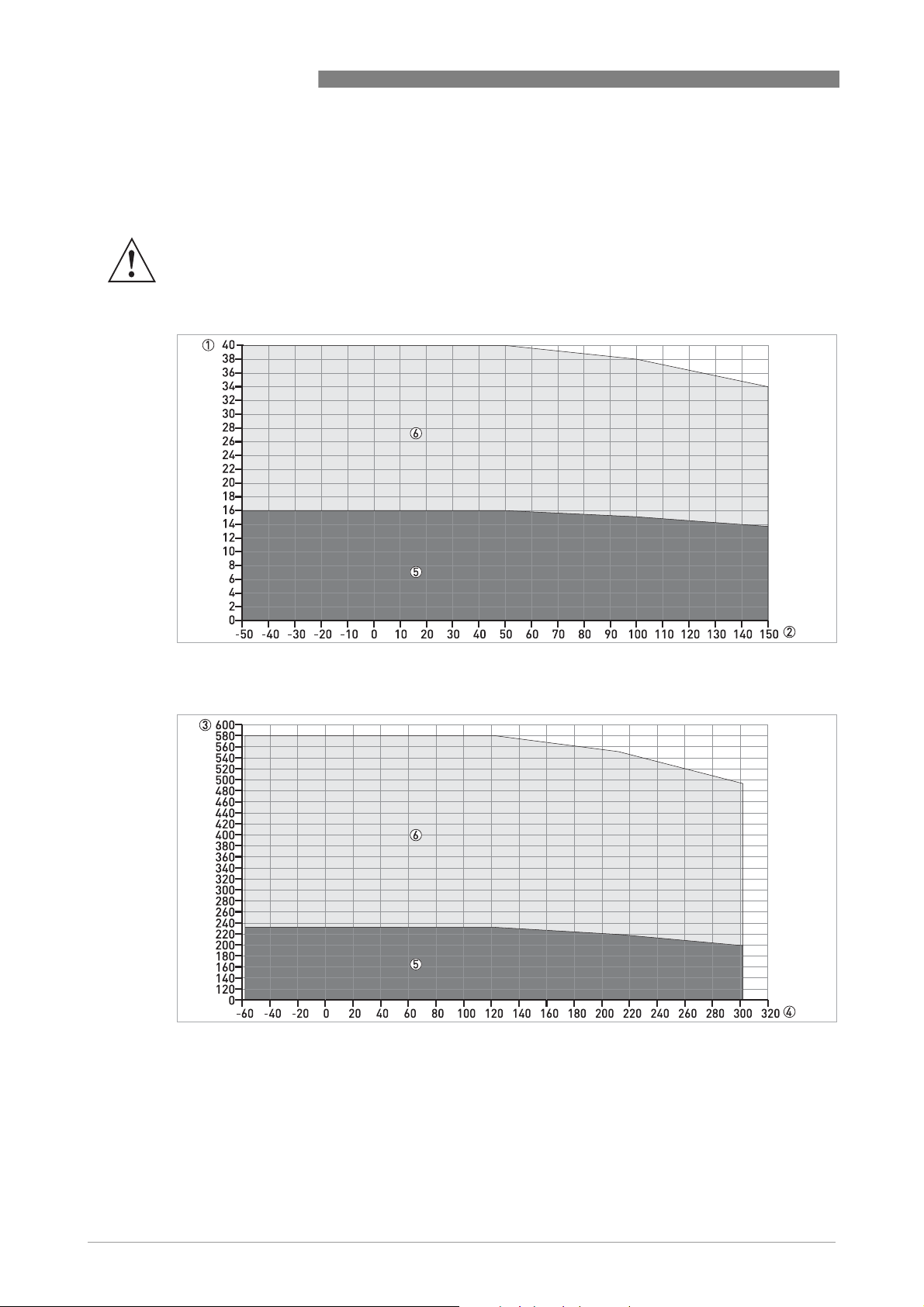
8 TECHNICAL DATA
8.4 Pressure ratings
This data is only applicable to the flanged version of the device.
WARNING!
Make sure that the devices are used within their operating limits. This will depend on the device
version, feedthrough material and process seal materal.
EN flanges
OPTIWAVE 1010
Figure 8-4: Pressure / temperature rating (EN 1092-1), flange connections, in °C and barg
Figure 8-5: Pressure / temperature rating (EN 1092-1), flange connections, in °F and psig
1 p [barg]
2 T [°C]
3 p [psig]
4 T [°F]
5 Flange connection, PN16
6 Flange connection, PN40
54
www.krohne.com 09/2014 - 4003537401 - MA OPTIWAVE 1010 R01 en
Page 55

OPTIWAVE 1010
8.5 Dimensions and weights
Device versions
Figure 8-6: Device versions
1 Non-Ex or Ex i-approved version (aluminium housing – standard or high-pressure (HP) version)
2 High-temperature / high-pressure (HT/HP) version
3 Non-Ex or Ex d-approved version (stainless steel housing – standard version)
Device versions: Dimensions in mm and inches
TECHNICAL DATA 8
Dimensions Device versions
Aluminium:
non-Ex or Ex i-approved
Aluminium:
HT/HP
Stainless steel:
non-Ex or Ex d-approved
(standard or HP)
[mm] [inches] [mm] [inches] [mm] [inches]
a 98 3.86 98 3.86 99.5 3.92
b 178 7.01 278 10.94 189 7.44
c 138 5.43 138 5.43 133 5.24
d 153 6.02 253 9.96 164 6.46
e 14 0.55 14 0.55 14 0.55
f 42.4 1.67 42.4 1.67 42.4 1.67
g 90 3.54 90 3.54 90 3.54
h 64.5 2.54 164 6.47 60 2.36
www.krohne.com09/2014 - 4003537401 - MA OPTIWAVE 1010 R01 en
55
Page 56
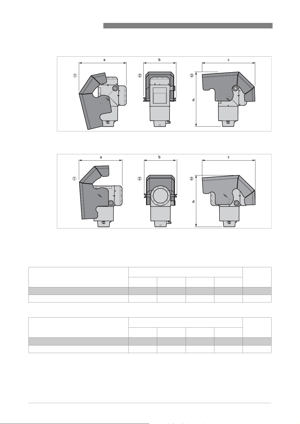
8 TECHNICAL DATA
Weather protection option
Figure 8-7: Weather protection option for Compact / Vertical and Remote versions
OPTIWAVE 1010
Figure 8-8: Weather protection option for Compact / Horizontal and Remote versions
1 Left side (with weather protection open)
2 Rear view (with weather protection closed)
3 Right side (with weather protection closed)
Dimensions and weights in mm and kg
Weather protection Dimensions [mm] Weights
[kg]
a b c d
Compact / Vertical or Remote versions 244 170 274 285 1.6
Compact / Horizontal or Remote versions 221 170 274 269 1.6
Dimensions and weights in inches and lb
Weather protection Dimensions [inches] Weights
a b c d
Compact / Vertical or Remote versions 9.6 6.7 10.8 11.22 3.5
Compact / Horizontal or Remote versions 8.7 6.7 10.8 10.59 3.5
[lb]
56
www.krohne.com 09/2014 - 4003537401 - MA OPTIWAVE 1010 R01 en
Page 57

OPTIWAVE 1010
TECHNICAL DATA 8
Weights
Type of device Weights
Aluminium Stainless steel
[kg] [lb] [kg] [lb]
Non-Ex / intrinsically-safe (Ex i / IS)
Standard x.x x.x x.x x.x
High temperature x.x x.x x.x x.x
Explosion proof (Ex d / XP)
Standard x.x x.x x.x x.x
www.krohne.com09/2014 - 4003537401 - MA OPTIWAVE 1010 R01 en
57
Page 58

9 DESCRIPTION OF HART INTERFACE
9.1 General description
The HART® Protocol is an open digital communication protocol for industry. It is free to use by
anyone. It is included in the software embedded in signal converters of HART-compatible
devices.
OPTIWAVE 1010
There are 2 classes of devices which support the HART
®
Protocol: operating devices and field
devices. There are 2 classes of operating devices (Master): PC-supported workstations (Primary
Master) and manual control units (Secondary Master). These can be used in control centres and
other locations. HART
®
field devices include sensors, converters and actuators. Field devices
include 2-wire and 4-wire devices, and also intrinsically-safe versions for use in hazardous
areas.
There are 2 primary operation modes for HART-compatible devices: point-to-point mode and
multi-drop mode.
If the device is used in point-to-point mode, the HART
®
Protocol uses the Bell 202 Frequency
Shift Keying (FSK) standard to put a digital signal on top of the 4...20 mA signal. The connected
®
device sends and receives digital signals that agree with the HART
Protocol, and sends analog
signals at the same time. Only 1 device can be connected to the signal cable.
If the device is used in multi-drop mode, the network only uses a digital signal that agrees with
the HART
®
Protocol. The loop current is set to 4 mA. You can connect a maximum of 15 devices
to the signal cable.
An FSK or HART
®
modem is included in field devices and manual control units. It is necessary to
have an external modem for PC-supported workstations. The external modem is connected to
the serial interface.
9.2 Software description
HART® identification codes and revision numbers
Manufacturer ID: 0x45
Device: 0xBF
Device Revision: 1
DD Revision 1
HART® Universal Revision:
FC 375/475 system SW.Rev.: ≥ 2.0
AMS version: ≥ 7.0
PDM version: ≥ 6.0
FDT version: 1.2
9.3 Connection variants
The signal converter is a 2-wire device with 4...20 mA current output and HART® interface.
• Multi-Drop Mode is supported
In a Multi-Drop communication system, more than 1 device is connected to a common
transmission cable.
6
58
www.krohne.com 09/2014 - 4003537401 - MA OPTIWAVE 1010 R01 en
Page 59

OPTIWAVE 1010
• Burst Mode is not supported
DESCRIPTION OF HART INTERFACE 9
There are two ways of using the HART® communication:
• as Point-to-Point connection and
• as Multi-Drop connection with 2-wire connection.
9.3.1 Point-to-Point connection - analogue / digital mode
Point-to-Point connection between the signal converter and the HART® Master.
The current output of the device is passive.
Also.
9.3.2 Multi-Drop connection (2-wire connection)
Up to 15 devices may be installed in parallel (this signal converter and other HART® devices).
For an illustration of multi-drop networks.
For data on communication in multi-drop mode.
9.4 HART® device variables
The HART® dynamic variables PV (Primary Variable), SV (Secondary Variable), TV (Third Variable)
and 4V (Fourth Variable) can be assigned to any of the device variables.
The HART
example, assigned to level measurement.
®
dynamic variable PV is always connected to the HART® current output which is, for
9.5 Field Communicator 375/475 (FC 375/475)
The Field Communicator is a hand terminal from Emerson Process Management that is
®
designed to configure HART
used to integrate different devices into the Field Communicator.
9.5.1 Installation
CAUTION!
The Field Communicator cannot be used to correctly configure, operate or read data from the
device unless the Device Description (DD) file is installed.
and Foundation Fieldbus devices. Device Descriptions (DDs) are
System and software requirements for the Field Communicator
• System card that includes the "Easy Upgrade Option"
• Field Communicator Easy Upgrade Programming Utility
• HART
For more data, refer to the Field Communicator User’s Manual.
®
Device Description file
www.krohne.com09/2014 - 4003537401 - MA OPTIWAVE 1010 R01 en
59
Page 60

9 DESCRIPTION OF HART INTERFACE
9.5.2 Operation
INFORMATION!
The Field Communicator will not give you access to the service menu. A simulation is only
possible for current outputs.
The Field Communicator and the device's local display use almost the same procedures to
operate the signal converter. The online help for each menu item refers to the function number
given to each menu item on the local device display. Protection of settings is the same as on the
device's local display.
The Field Communicator always saves a complete configuration for communication with AMS.
OPTIWAVE 1010
For more data, refer to
HART
® menu tree for Basic-DD on page 62.
9.6 Asset Management Solutions (AMS)
The Asset Management Solutions Device Manager (AMS) is a PC program from Emerson
Process Management which is designed to configure and manage HART
Foundation-Fieldbus devices. Device Descriptions (DDs) are used to integrate different devices
into the AMS.
9.6.1 Installation
Please read the README.TXT file in the Installation Kit.
If the Device Description has not been installed at this time, install the Installation Kit HART
AMS. This .EXE file is given on the DVD-ROM supplied with the device. You can also download the
file from our website.
For installation data, refer to the "AMS Intelligent Device Manager Books Online" section "Basic
AMS Functionality > Device Configurations > Installing Device Types > Procedures > Install
device types from media".
9.6.2 Operation
®
, PROFIBUS and
®
INFORMATION!
For more data, refer to HART
®
menu tree for AMS on page 62
9.6.3 Parameter for the basic configuration
Due to AMS requirements and conventions, there are differences when operating the signal
converter with AMS and operating using the local keyboard. The service menu parameters are
not supported and simulation is only possible for current outputs. The online help for each
parameter contains its function number as a reference to the local device display.
60
www.krohne.com 09/2014 - 4003537401 - MA OPTIWAVE 1010 R01 en
.
Page 61

OPTIWAVE 1010
DESCRIPTION OF HART INTERFACE 9
9.7 Field Device Tool / Device Type Manager (FDT / DTM)
9.7.1 Installation
Before you operate the device, the Device Type Manager (Device DTM) must be installed in the
Field Device Tool Container. This .msi file is given on the DVD-ROM supplied with the device. You
can also download the file from our website. For installation and configuration data, refer to the
documentation that is supplied with the Device DTM on the DVD-ROM or in the "Downloads"
section of the website.
9.7.2 Operation
The DTM and the device's local display use almost the same procedures to operate the signal
converter. For more data, refer to
Operation
on page 30.
9.8 Process Device Manager (PDM)
The Process Device Manager (PDM) is a Siemens PC program designed to configure HART® and
PROFIBUS devices. Device Descriptions (DDs) are used to integrate different devices into the
PDM.
9.8.1 Installation
Install Device Description files supplied in the Device Install HART® PDM folder. This is
necessary for each type of field device that is used with SIMATIC PDM. This folder is available for
download from the website or on the DVD-ROM supplied with the device.
If you use PDM version 5.2, refer to PDM manual, section 11.1 - Install device / Integrate device
into SIMATIC PDM with Device Install.
If you use PDM version 6.0, refer to PDM manual, section 13 - Integrating devices.
For more data, refer to “readme.txt”. You can find this file in the Installation Kit.
9.8.2 Operation
INFORMATION!
For more data, refer to HART
There can be differences between the names of menus in the SIMATIC PDM software tool and
menus shown on the device display screen. Refer to the online help in SIMATIC PDM to find the
function number of each menu item. This function number agrees with the function number in
the device menus.
®
menu tree for PDM on page 64
.
Use the same procedure for the protection of parameters in the supervisor menu.
www.krohne.com09/2014 - 4003537401 - MA OPTIWAVE 1010 R01 en
61
Page 62

9 DESCRIPTION OF HART INTERFACE
9.9 HART® menu tree for Basic-DD
Abbreviations of the following tables:
Opt
•
Optional, depending on device version and configuration
Rd
Read only
•
9.9.1 Overview Basic-DD menu tree (positions in menu tree)
9.9.2 Basic-DD menu tree (details for settings)
9.10 HART® menu tree for AMS
Abbreviations of the following tables:
Opt
•
Optional, depending on device version and configuration
Rd
Read only
•
9.10.1 Overview AMS menu tree (positions in menu tree)
OPTIWAVE 1010
Process variables Measurements
Analog Output
Device Diagnostics Overview
Fatal Errors
Warnings (Maintenance required)
Warnings (Out of specifications)
Warnings (Function check)
Methods Access Right
Tests
Calibrate
Empty Spectrum
Conversion Table
Master reset
Configure / Setup Basic Setup Basic Parameters
Local Display
Application
Analog Output Output Functions
Output 1
Units
Device
HART ID
-
Conversion table
62
www.krohne.com 09/2014 - 4003537401 - MA OPTIWAVE 1010 R01 en
Page 63

OPTIWAVE 1010
DESCRIPTION OF HART INTERFACE 9
9.10.2 AMS menu tree (details for settings)
Process Variables
Measurements
Primary Output
Rd
Level
Reflection
Function I / Loop current
/ Distance Rd/ Volume/Mass/Flow Rd/ Ullage Volume/Mass/Flow Rd/
Rd
Device Diagnostics
Overview Primary variable out of limits / Non-primary variable out of limits / Primary
variable analog output saturated / Primary variable analog output fixed / Cold
Start / Configuration changed / Field device malfunction
Fatal Errors (Failure) Converter EEPROM error / Converter RAM error / Converter ROM error /
Sensor EEPROM error / Sensor RAM error / Sensor ROM error / Current
output drift / Sensor Microwave error / Converter Voltage error / Sensor
Voltage error / Internal Comm. error / Temperat. out of range / Sensor not
compatible / Sensor no signal / Sensor processing failure / Peak lost error /
Overfill error
Warnings (Maintenance
required)
Warnings (Out of
specification)
Warnings (Function check) Local operation on the device
Information Spectrum quality bad / Peak lost in tank bottom / Temperature out of range
Empty spectrum invalid / Signal weak / Signal strong / Bad Measurement
Quality / Temperature < -35°C / Temperature > +75°C
Peak lost / Overfill / Temperature out of range
for HMI
Rd
/ PV Percent of Range
Rd
Methods
Acess right Log In/Log Out / Password Yes/No
Tests Test Output I
Calibrate D/A Trim
Empty Spectrum Empty Spec. Rec.
Conversion Table Input table / Delete table
Reset Restart Device / Reset Factory / Rst Conf. Chged flag
Configure / Setup
Basic Setup Basic Parameters Tank Height / Blocking Distance / Time Constant /
Stillwell Enabled / Stillwell Diameter / Stillwell
Height / Antenna Extension / Antenna Type /
Distance Piece / Tag
Local Display Display length unit / Display volume unit / Language
Application Tank Type / Tracking velocity / Epsilon R product /
Measuring Mode / Overfill Detection / Multiple
Reflection / Empty Spectrum On/Off
Analog Output Output Functions Function I / SV / TV / QV
Output 1 Output Range / Output Error Delay / LRV / URV
Units Length unit (HART) / Volume unit (HART) / Time constant
Device Model / Manufacturer / Fld dev rev / Software rev / Write protect / Interface
Rd
option
number / Sensor Firmware number / HMI Firmware number
/ Descriptor / Message / Date / Serial number / Converter firmware
www.krohne.com09/2014 - 4003537401 - MA OPTIWAVE 1010 R01 en
63
Page 64

9 DESCRIPTION OF HART INTERFACE
HART ID Tag / Polling address / Device ID
Universal revision / Fld dev rev Num /
Num request preams
Conversion table
Number of points / Length unitRd/ Conversion unitRd/
Points (1...30 level-conversion pairs)
9.11 HART® menu tree for PDM
Abbreviations of the following tables:
Opt
•
Optional, depending on device version and configuration
Rd
Read only
•
Cust
•
•
9.11.1 Overview PDM menu tree (positions in menu tree)
Overview: Menu Device
Custody lock protection
Loc
Local PDM, affects only PDM views
Communication Path
Download To Device...
Upload To PG/PC...
Update Diagnosis Status
Configuration and Test
Access Rights
watch status
OPTIWAVE 1010
Overview: Menu View
Measurements Level Value
Distance Value
Ullage Value
Reflection Value
Yt diagram
Diag / Service
Toolbar
Status Bar
Update
64
www.krohne.com 09/2014 - 4003537401 - MA OPTIWAVE 1010 R01 en
Page 65

OPTIWAVE 1010
DESCRIPTION OF HART INTERFACE 9
Overview: PDM parameters
Configuration and Test Info. Identification
Supervisor Test
Access rights
HART variables
9.11.2 PDM menu tree (details for settings)
Device Menu
Output
Basic Parameters
Signal Output
Application
Display
Conversion Table
Reset
Communication Path
Downoad To Device...
Upload To PG/PC...
Update Diagnosis Status
Configuration and Test
Info. Identification
Output
Supervisor Test Test I
Basic Parameters Tank Height / Blocking Distance / Time Constant /
Signal Output Function I / Output Range / PV URV / PV LRV /
Application Tank Type / Tracking Velocity / Epsilon R product /
Display Language / Display Length Unit / Display
Conversion Table Input Table / Delete Table
Reset Warm start (function to restart the device) / Factory
Serial Number Rd/ Converter Firmware
version
Firmware version
Function IRd/ Output RangeRd/ PV URVRd/ PV
LRV
Pipe Enable / Pipe Diameter / Pipe Height /
Antenna Extension / Antenna Type / Distance
Piece / Length Unit (HART) / Conversion Unit
(HART)
Output Error Delay / Current Output Calibration 1
Measuring Mode / Overfill Detection / Multiple
Reflection / Empty Spectrum Recording / Empty
Spectrum On/Off
Conversion Unit
Reset / Reset Configuration Changed Flag
Rd
/ Sensor Firmware versionRd/ HMI
Rd
/ Output Error Delay
Rd
Rd
www.krohne.com09/2014 - 4003537401 - MA OPTIWAVE 1010 R01 en
65
Page 66

9 DESCRIPTION OF HART INTERFACE
Access rights
Access level
Method Login
Method Entry Code
HART Variables
Rd
OPTIWAVE 1010
1 Poll addr / 2 Tag / 3 Hardware revRd/ 4 Software revRd/ 5Descriptor/ 6Date/ 7Message/
8 Manufacturer
preams
1 Current Output Calibration is available only if the service password is used
Rd
Rd
/ 9 ModelRd/ Dev idRd/ Universal idRd/ Fld dev revRd/ Num req preamsRd/ Num resp
/ Write protectRd/ Production numberRd/ Final asmbly numRd/ PV is / SV is / TV is / QV is
View Menu
Measurements
Measurements Level Value / Distance Value / Volume Value / Ullage Value / Reflection Value
Output Level value / Loop curent / % Range
Yt diagram
Diag / Service
Standard Status Device status PV Analog Channel Saturated / Configuration
Device-specific status Device failures Sensor Microwave error / Current Output Drift /
Device Warning
(Maintenance
Required)
Device Warning (Out of
Specification)
Info First Start / Spectrum Quality Bad / Peak Lost in
changed
Sensor ROM error / Sensor RAM error / Sensor
EEPROM error / Converter ROM error / Converter
RAM error / Converter EEPROM error
Sensor No Signal / Sensor Not Compatible /
Temperature Out of Range / Internal
Communication Error / Sensor Voltage Error /
Converter Voltage Error
Peak Lost Error / Overfill Error
Empty Spectrum Invalid / Signal Weak / Signal
Strong / Bad Measurement Quality / Temperature
Below -35°C / Temperature Above +75°C
Overfill Warning / Peak Lost Warning /
Temperature Out of Range Warning
Tank Bottom / Temperature out of range for HMI
66
Toolbar
Status Bar
Update
www.krohne.com 09/2014 - 4003537401 - MA OPTIWAVE 1010 R01 en
Page 67

OPTIWAVE 1010
10.1 Order code
Make a selection from each column to get the full order code. The characters of the order code
highlighted in light grey describe the standard.
VF01 4 OPTIWAVE 1010 Non-Contact Radar (FMCW) Level Meter
Converter version (Housing material – protection class)
1 OPTIWAVE 1010: Compact version (Aluminium – IP 66/67)
2 OPTIWAVE 1010: Compact version (Stainless steel – IP 66/67)
Approval 1
0 Without
1 ATEX Ex ia IIC T3…T6 + DIP 2
2 ATEX Ex d ia IIC T3..T6 + DIP 2
4 ATEX Ex ic IIC T3…T6 + DIP 2
6 IECEx Ex ia IIC T3…T6 + DIP 2
7 IECEx Ex d ia IIC T3…T6 + DIP 2
8 IECEx Ex ic IIC T3…T6 + DIP 2
A cFMus IS CL I/II/III, DIV 1, GPS A-G; CL I, Zone 0/20, Ex ia IIC/IIIC T3…T6
B cFMus XP-IS/DIP CL I/II/III, DIV 1, GPS A-G (A not for CAN); CL I, Zone 0/20, Ex d/tb IIC/IIIC T3…T6
C cFMus NI CL I/II/III, DIV 2, GPS A-G; CL I, Zone 2, Ex nA IIC T3...T6
L NEPSI Ex ia IIC T3 ~ T6 + DIP 2
M NEPSI Ex d ia IIC T3 ~ T6 + DIP 2
Other approval
0 Without
4 CRN (Canadian Registration Number)
A WHG
Process seal – Temperature / Pressure / Material / Remarks (material to be checked by the
customer)
0 Without
1 -40°C...+100°C (-40°F…+212°F) / -1…16 barg (-14.5…232 psig) / FKM/FPM
2 -50°C...+100°C (-58°F…+212°F) / -1…16 barg (-14.5…232 psig) / EPDM
3 -20°C...+100°C (-4°F…+212°F) / -1…16 barg (-14.5…232 psig) / Kalrez® 6375
5 -40°C...+150°C (-40°F…+302°F) / -1...40 barg (-14.5…580 psig) / FKM/FPM 3
6 -50°C...+150°C (-58°F…+302°F) / -1...40 barg (-14.5…580 psig) / EPDM 3
7 -20°C...+150°C (-4°F…+302°F) / -1...40 barg (-14.5…580 psig) / Kalrez® 6375 3
VF01 4 Order code (complete this code on the pages that follow)
APPENDIX 10
www.krohne.com09/2014 - 4003537401 - MA OPTIWAVE 1010 R01 en
67
Page 68

10 APPENDIX
Antenna (Antenna type / Material)
0 Without
1 Metallic Horn for pipe Ø42.4 × 2 / 316L
2 Metallic Horn for pipe Ø60.3 × 2 / 316L
3 Metallic Horn for pipe Ø60.3 × 2.77 / 316L
4 Metallic Horn for pipe Ø 0.3 × 3.9 / 316L
5 Metallic Horn for BM26A
A Metallic Horn for pipe Ø 42.4 × 2 / HC22
B Metallic Horn for pipe Ø 60.3 × 2 / HC22
C Metallic Horn for pipe Ø 60.3 × 2.77 / HC22
D Metallic Horn for pipe Ø 60.3 × 3.9 / HC22
0 Process connection: Size / Pressure rating / Flange face finish
0 0 0 Without
EN / DIN Flanges – EN 1092-1 4
G E 1 DN40 PN16 – Type B1
G G 1 DN40 PN40 – Type B1
H E 1 DN50 PN16 – Type B1
H G 1 DN50 PN40 – Type B1
ASME B16.5 / ANSI Flanges 4
G 1 A 1½¨ 150 lb RF (Raised Face)
G 2 A 1½¨ 300 lb RF (Raised Face)
H 1 A 2¨ 150 lb RF (Raised Face)
H 2 A 2¨ 300 lb RF (Raised Face)
L 1 A 3¨ 150 lb RF (Raised Face)
L 2 A 3¨ 300 lb RF (Raised Face)
JIS B2220 Flanges
G U P 40A JIS 10K RF (Raised Face)
H U P 50A JIS 10K RF (Raised Face)
L U P 80A JIS 10K RF (Raised Face)
Alternative flange face finish
2 Type B2, EN 1092-1 (surface roughness must be specified in the order)
3 Type C, EN 1092-1 (Tongue)
4 Type D, EN 1092-1 (Groove)
5 Type E, EN 1092-1 (Spigot)
6 Type F, EN 1092-1 (Recess)
B FF, ASME B16.5 (Flat face)
VF01 4 0 Order code (complete this code on the pages that follow)
OPTIWAVE 1010
68
www.krohne.com 09/2014 - 4003537401 - MA OPTIWAVE 1010 R01 en
Page 69

OPTIWAVE 1010
APPENDIX 10
Output
1 2-wire / 4...20mA passive HART
Cable entry / Cable gland
1 M20×1.5 / without
2 M20×1.5 / Plastic (Non-Ex: black; Ex i: blue)
3 M20×1.5 / Brass
4 M20×1.5 / Stainless Steel
A ½ NPT (Brass) / without
B ½ NPT (Stainless Steel) / without
Housing (Orientation / Display / Weather protection)
A Vertical / Without / Without
D Vertical / Without / With
0 Version
0 KROHNE (RAL 9006 / RAL 5005)
6 KROHNE USA (FCC)
A KMIC L (for liquid applications)
0 0 0 Calibration certificate
0 Without for std. accuracy ±10 mm (0.39¨) up
to 8 m (32.81 ft)
1 Calibration certificate ±5mm (0.2¨) 2 points
TAG Number
0 Without
2 Tag No. on stainless steel plate
(16 characters max.)
Other constructions
0 Without
1 NACE design
(MR0175 / MR0103 / ISO 15156)
VF01 4 0 1 0 0 0 0 Order code
1 For more data, refer to the Technical data section (Approvals and certification)
2 DIP= Dust Ignition Proof
3 This device also has a Metaglas® process seal and high-temperature (HT) distance piece
4 Other flange faces are available. Refer to your local supplier for more data. Flanges with the PTFE Wave Horn antenna option have a
slip on-type design with an anti-blowout feature.
www.krohne.com09/2014 - 4003537401 - MA OPTIWAVE 1010 R01 en
69
Page 70

10 APPENDIX
10.2 Spare parts
We supply spare parts for this device. When you send an order for a mechanical spare part, use
the reference numbers in the table that follows. When you send an order for an electronic spare
part, refer to
Other spare parts
Order code
OPTIWAVE 1010
on page 67 and use the VF01 order code.
Figure 10-1: Other spare parts
1 Cover
2 Cover for Ex d module
3 Set of fasteners for housing (lock screw, gaskets)
4 Cable gland
DANGER!
Remote version: Make sure that replacement signal cables for Ex-approved devices are supplied
by the manufacturer. Use of this signal cable is mandatory.
Item Description Quantity Part reference
1 Cover 1 XF01xxxxxx
2 Cover for Ex d module 1 1 XF01xxxxxx
3 Set of fasteners for housing (lock screw, gaskets) 1 screw, 10 gaskets XF01xxxxxx
4 Cable gland / M20×1.5; Plastic; Black; Non-Ex 1 XF01xxxxxx
Cable gland / M20×1.5; Plastic; Blue; Ex i 1 XF01xxxxxx
Cable gland / M20×1.5; Brass; Ex d 1 XF01xxxxxx
Cable gland / M20×1.5; Stainless Steel 1 XF01xxxxxx
1 Ex d-approved devices only
70
www.krohne.com 09/2014 - 4003537401 - MA OPTIWAVE 1010 R01 en
Page 71

OPTIWAVE 1010
10.3 Accessories
We supply accessories for this device. When you send an order for a accessories, please give the
reference numbers that follow:
APPENDIX 10
Figure 10-2: Accessories
1 Viator RS232 / HART converter
2 Viator USB / HART converter
Item Description Quantity Part reference
1 Viator RS232 / HART converter 1 XF01xxxxxx
2 Viator USB / HART converter 1 XF01xxxxxx
www.krohne.com09/2014 - 4003537401 - MA OPTIWAVE 1010 R01 en
71
Page 72

10 APPENDIX
10.4 Glossary
D
Dead zone Non-measurement zone.
Dielectric constant An electrical property of the product to be measured used in Radar
Distance The distance from the face of flange to the level (1 product) or the surface
DTM Device Type Manager. A driver for use in the PACTware™ program. All data
E
Electromagnetic compatibility Defines how much a device influences or is influenced by other devices that
OPTIWAVE 1010
measurement. Also known as εr, DK and relative permittivity. Defines the
strength of the wave reflected back to the device's signal converter.
of the top product (2 or more products). See the diagrams at the end of this
section.
and functions of the device are included in it.
generate electromagnetic fields during operation. Refer to European
standard EN 61326-1 for further details.
F
FMCW Frequency-modulated continuous-wave radar technology. The signal is
continuously present, but the frequency is modulated, usually in
successive linear ramps over time (frequency sweeps).
H
Hazardous area An area with a potentially explosive atmosphere. Trained personnel can
Horn (cone) antenna A common antenna for most applications. It is used for the controlled
install and use a device in this area. The device must be ordered with the
appropriate options. The device requires approvals (ATEX, IECEx, FM, CSA,
NEPSI etc.) related to site specifications. You can find more data about
hazardous areas in the Ex Manuals and Ex Certificates of Compliance.
emission and collection of radar signals.
I
Interference signals False radar reflections.
L
Level Height from the bottom of the tank (user-defined) to the surface of the top
product (Tank height – distance). See the diagrams at the end of this
section.
72
M
Mass Total mass of tank contents.
www.krohne.com 09/2014 - 4003537401 - MA OPTIWAVE 1010 R01 en
Page 73

OPTIWAVE 1010
O
Operators Users who can choose how to display measurements. They cannot
P
PACTware™ Software that operates and configures field devices from a remote
R
Radar reflection Signal reflected from the surface of the tank contents.
S
Signal converter A set of electronic components in the device that send the measurement
Supervisor Users who can configure the device in supervisor mode. They cannot
APPENDIX 10
configure the device in supervisor mode.
workstation. It is not necessary to use fieldbus software or programs
developed by the manufacturer.
signal through some signal filters. They identify and measure the level of
the tank contents.
configure the device in service mode.
U
Ullage volume Unfilled volume. See the diagrams at the end of this section.
V
Volume Total volume of tank contents.
www.krohne.com09/2014 - 4003537401 - MA OPTIWAVE 1010 R01 en
73
Page 74

10 APPENDIX
Figure 10-3: Measurement definitions: distance
1 Distance
2 Dead zone
3 Flange facing
4 Gas (Air)
5 Tank height
6 Ullage volume or mass
OPTIWAVE 1010
74
Figure 10-4: Measurement definitions: level
1 Level
2 Volume or mass
www.krohne.com 09/2014 - 4003537401 - MA OPTIWAVE 1010 R01 en
Page 75

OPTIWAVE 1010
NOTES 11
www.krohne.com09/2014 - 4003537401 - MA OPTIWAVE 1010 R01 en
75
Page 76

KROHNE product overview
• Electromagnetic flowmeters
• Variable area flowmeters
• Ultrasonic flowmeters
• Mass flowmeters
• Vortex flowmeters
• Flow controllers
• Level meters
• Temperature assemblies
• Pressure transmitters
• Analysis products
• Products and systems for the oil & gas industry
• Measuring systems for the marine industry
Head Office KROHNE Messtechnik GmbH
Ludwig-Krohne-Str. 5
47058 Duisburg (Germany)
Tel.:+49 203 301 0
Fax:+49 203 301 103 89
info@krohne.com
© KROHNE 09/2014 - 4003537401 - MA OPTIWAVE 1010 R01 en - Subject to change without notice.
The current list of all KROHNE contacts and addresses can be found at:
www.krohne.com
 Loading...