

Page 1
Supplementary instructions
Supplementary instructions
IFC 300
IFC 300
IFC 300IFC 300
Supplementary instructions Supplementary instructions
Signal converter for electromagnetic flowmeters
Description of PROFIBUS interface
Description of PROFIBUS interface
Description of PROFIBUS interfaceDescription of PROFIBUS interface
PROFIBUS PA:
PROFIBUS PA:
PROFIBUS PA:PROFIBUS PA:
PROFIBUS device with MBP Physical Interface and PA Profile 3.0 (V3.0.2 / 100811)
PROFIBUS DP:
PROFIBUS DP:
PROFIBUS DP:PROFIBUS DP:
PROFIBUS device with RS485 Physical Interface and PA Profile 3.0 (V3.0.2 / 100811)
© KROHNE 02/2011 - 4001086601 - AD IFC 300 PROFIBUS R01 en
Page 2

CONTENTS
IFC 300
1 Safety instructions 4
1.1 Scope of the document..................................................................................................... 4
1.2 Scope of delivery............................................................................................................... 4
1.3 Special notes .................................................................................................................... 4
2 PROFIBUS DP 5
2.1 Software history ............................................................................................................... 5
2.2 System configuration of PROFIBUS DP network............................................................. 6
2.3 Electrical connection for DP signal converter................................................................. 7
2.4 Technical data................................................................................................................... 9
2.5 GSD files for the data transfer ....................................................................................... 10
2.5.1 Cyclic data exchange............................................................................................................. 10
2.5.2 Baud rate............................................................................................................................... 10
2.5.3 Ident.-No. supported............................................................................................................. 10
2.5.4 Manufacturer specific GSD files: KR024500.GSD and KR014500.GSD ................................ 11
2.5.5 Differencies of the manufacturer specific GSD files: KR024500.GSD and KR014500.GSD. 13
2.5.6 Profile specific GSD file: PA039740.GSD .............................................................................. 13
2.5.7 Using the display menu to distinguish between Rev 1 and Rev 2 ........................................13
3 PROFIBUS PA 14
3.1 Software history ............................................................................................................. 14
3.2 System configuration of PROFIBUS PA network ........................................................... 16
3.3 Electrical connection for PA signal converter ............................................................... 17
3.4 Technical data................................................................................................................. 18
3.5 GSD files for the data transfer ....................................................................................... 19
3.5.1 Cyclic data exchange............................................................................................................. 19
3.5.2 Ident.-No. supported............................................................................................................. 19
3.5.3 Manufacturer specific GSD files: KR024501.GSD and YP024501.GSD................................. 20
3.5.4 Profile specific GSD file: PA139740.GSD .............................................................................. 22
3.5.5 Using the display menu to distinguish the current revision of the device (PA) ................... 23
3.6 Signal converter IFC 300 PROFIBUS PA with MBP interface as replacement for older
signal converter IFC 090 PA.................................................................................................. 23
3.6.1 Ident.-No. supported............................................................................................................. 23
3.6.2 Manufacturer specific GSD files (PA): KROHF401.GSD and YP01F401.GSD for the older sig-
nal converter IFC090 with PROFIBUS MBP interface.................................................................... 23
4 Application profile 25
4.1 Function blocks .............................................................................................................. 25
4.2 Data structure of function block output values ............................................................. 25
4.2.1 Float value............................................................................................................................. 25
4.2.2 Status value........................................................................................................................... 26
4.3 Diagnosis parameter ...................................................................................................... 28
4.3.1 Diagnosis............................................................................................................................... 28
4.3.2 DIAGNOSIS (if "Classic Status" and "Diagnosis" selected).................................................. 28
4.3.3 DIAGNOSIS_EXTENSION (if "Classic Status" and "Diagnosis" selected) ............................ 30
4.3.4 Mapping of DIAGNOSIS_EXTENSION bits into DIAGNOSIS bits........................................... 31
2
www.krohne.com 02/2011 - 4001086601 - AD IFC 300 PROFIBUS R01 en
Page 3

IFC 300
CONTENTS
5 Profibus settings 34
5.1 Menu A, quick setup ....................................................................................................... 34
5.2 Menu B, test.................................................................................................................... 34
5.3 Menu C, setup................................................................................................................. 35
5.4 Menu D, service .............................................................................................................. 38
6 Notes 39
www.krohne.com02/2011 - 4001086601 - AD IFC 300 PROFIBUS R01 en
3
Page 4

1 SAFETY INSTRUCTIONS
1.1 Scope of the document
These instructions are supplementary to the signal converter Handbook. For all other data, use
the relevant chapters of the Handbook. If you do not have this document, please contact the
nearest office or download them from the manufacturer's internet site.
INFORMATION!
The information in this chapter only contains the data applicable to PROFIBUS communication.
The technical data in the Handbook shall be valid in its current version, provided that it is not
rendered invalid or replaced by this supplement.
1.2 Scope of delivery
The information in this chapter only contains the data applicable to PROFIBUS communication.
The technical data in the Handbook shall be valid in its current version, provided that it is not
rendered invalid or replaced by this supplement.
A device for PROFIBUS communication is supplied with:
IFC 300
• Supplementary instructions for PROFIBUS communication
• PROFIBUS device data files (GSD) on a CD-ROM supplied with the device
1.3 Special notes
Don't switch off (power off) the signal converter immediately after manual change of parameter
values:
• Please wait approx. 10 seconds before you switch off the signal converter after you have done
both a parameter download via PROFIBUS or a manual change of a parameter value via the
local display.
• Please wait approx. 15 seconds before you switch off the signal converter after you have
carried out a "Factory Reset" (PROFIBUS "Coldstart") via PROFIBUS or local display.
"Deactivation of the Service Parameter Lock" of the signal converter via PROFIBUS:
• After writing down the service password (via PROFIBUS) the "Deactivation of the Service
Parameter Lock" will last at least 10 minutes if the internal password timer of the signal
converter won't be retriggered by writing this password again. The "Deactivation of the
Service Parameter Lock" will be terminated at once by a PROFIBUS Coldstart / Warmstart or
if the internal password timer of the signal converter elapsed.
4
www.krohne.com 02/2011 - 4001086601 - AD IFC 300 PROFIBUS R01 en
Page 5

IFC 300
2.1 Software history
Issued Signal converter Application program System integration
PROFIBUS DP 2
Mth./
Hardware Firmware Hardware Software Driver Version Model name
year
04/05
09/05
01/06 Signal
04/08 Signal
Signal
converter
with
RS485
interface +
PA Profile
3.0
(special)
converter
with
RS485
interface +
PA Profile
3.0
(special)
converter
with
RS485
interface +
PA Profile
3.0
V1.1.3 / 050413
V1.2.0 / 060215
V2.0.0 / 060112
V2.0.0 / 060126
V3.0.2 / 080422 Simatic
Simatic
PCS7
other SPS
of other
manufact.
Laptop - DD
Simatic
PCS7
other SPS
of other
manufact.
Laptop / PC PDM
PCS7
other SPS
of other
manufact.
Laptop / PC PDM
HW Config
other
Software of
other SPS
manufact.
- DTM ≥ - -
HW Config
other
Software of
other SPS
manufact.
(≥ 6.0 SP3)DD(Ident.-No.)
Pactware DTM ≥ GFP*DTM1.3.1
HW Config
other
Software of
other SPS
manufact.
(≥ 6.0 SP3)DD(Ident.-No.)
Pactware DTM ≥ GFP*DTM1.3.1
GSD
manuf.
specific
GSD
profile
specific
(Ident.-No.)
GSD
manuf.
specific
GSD
profile
specific
GSD
manuf.
specific
GSD
profile
specific
KR014500.GSD IFC300(RS485)
PA039740.GSD Flow with 1AI,
- -
KR014500.GSD*
KR024500.GSD
PA039740.GSD Flow with 1AI,
I3P*DD0300.03** -
FDT1.2
KR014500.GSD*
KR024500.GSD
PA039740.GSD Flow with 1AI,
I3P*DD0300.03** -
FDT1.2
Rev.1
1TOT (PhyL 0)
IFC300(RS485)
Rev.1
IFC300(RS485)
Rev.2
1TOT (PhyL 0)
-
IFC300(RS485)
Rev.1
IFC300(RS485)
Rev.2
1TOT (PhyL 0)
-
www.krohne.com02/2011 - 4001086601 - AD IFC 300 PROFIBUS R01 en
5
Page 6
2 PROFIBUS DP
Issued Signal converter Application program System integration
IFC 300
Mth./
Hardware Firmware Hardware Software Driver Version Model name
year
01/11 Signal
converter
with
RS485
interface +
PA Profile
3.0
*: If the GSD file "KR014500.GSD" is used, there will be supported only a limited amount of
functions by the software version (V1.2.0 / 060215 or V2.0.0 / 060112): I&M functions and fail safe
mode are not accessible. For full support of all profile specific or manufacturer specific
functions/parameters use the GSD file "KR024500.GSD".
GFP*: Generic Flow PROFIBUS
I3P*: IFC300 PROFIBUS
**: PDM 5.2 PDM 6.0
V3.0.2 / 100811 Simatic
PCS7
other SPS
of other
manufact.
Laptop / PC PDM
HW Config
other
Software of
other SPS
manufact.
(≥ 6.0 SP3)DD(Ident.-No.)
Pactware DTM ≥ GFP*DTM1.3.1
GSD
manuf.
specific
GSD
profile
specific
KR014500.GSD*
KR024500.GSD
PA039740.GSD Flow with 1AI,
I3P*DD0300.03** -
FDT1.2
I3P*DTM1.0.7
FDT1.2
IFC300(RS485)
Rev.1
IFC300(RS485)
Rev.2
1TOT (PhyL 0)
-
-
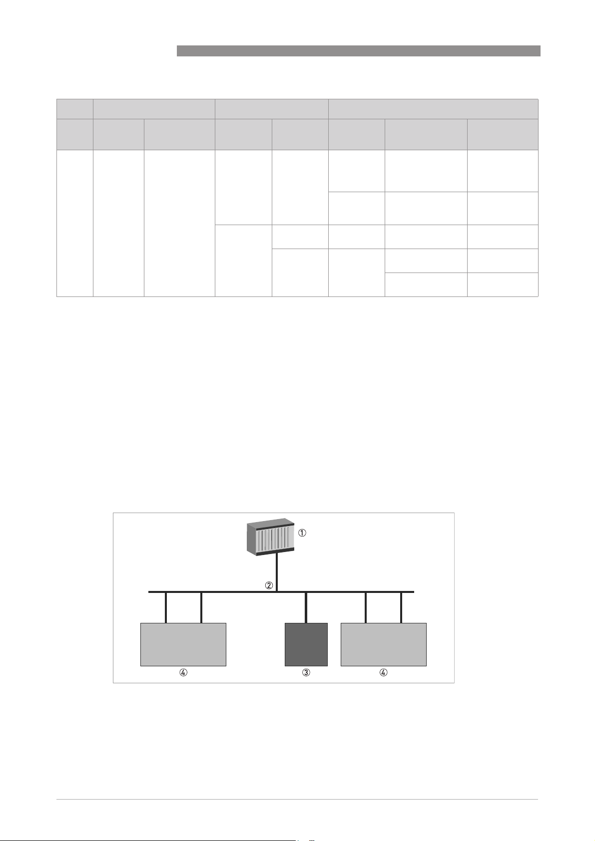
2.2 System configuration of PROFIBUS DP network
The following diagram shows a typical network configuration with PROFIBUS devices with RS485
interface in a non-hazardous environment. The PROFIBUS devices with RS485 interface do not
need any segment coupler. They are connected directly to the PROFIBUS DP network.
Figure 2-1: PROFIBUS DP network
1 SPS
2 PROFIBUS DP with max. 12 Mbit/s
3 Signal converter
4 Other devices with PROFIBUS RS485 interface
6
www.krohne.com 02/2011 - 4001086601 - AD IFC 300 PROFIBUS R01 en
Page 7
IFC 300
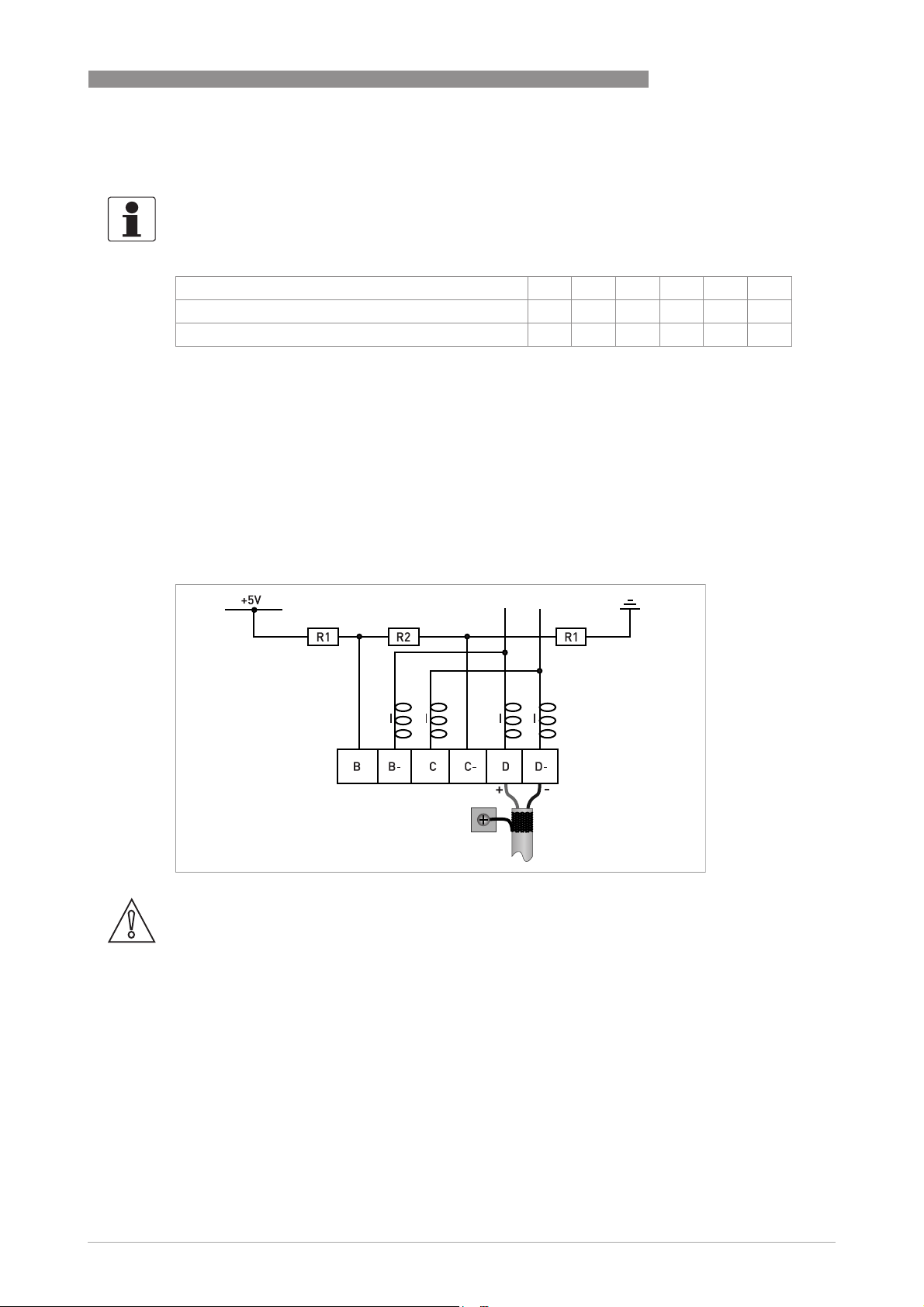
2.3 Electrical connection for DP signal converter
INFORMATION!
For a detailed description of the electrical connections please refer to the standard signal
converter handbook.
Signal converter terminals B B- C C- D D-
PROFIBUS designation T +B -A -T +B -A
1 2 3 4 5 6
1 Termination positive
2 TxD+/RxD+ second connection
3 TxD-/RxD- second connection
4 Termination negative
5 TxD+/RxD+ first connection
6 TxD-/RxD- first connection
PROFIBUS DP 2
External connection with spur
CAUTION!
Spurs are not allowed at high data rates!
I = 110 nH
R1 = 390 Ω
R2 = 220 Ω
www.krohne.com02/2011 - 4001086601 - AD IFC 300 PROFIBUS R01 en
7
Page 8

2 PROFIBUS DP
External connection at last device with active internal bus termination
I = 110 nH
R1 = 390 Ω
R2 = 220 Ω
IFC 300
External connection to a trunk
1 e.g. incoming data lines
2 e.g. outgoing data lines
I = 110 nH
R1 = 390 Ω
R2 = 220 Ω
8
www.krohne.com 02/2011 - 4001086601 - AD IFC 300 PROFIBUS R01 en
Page 9

IFC 300
2.4 Technical data
Hardware
Type PROFIBUS RS485 interface according to IEC 61158-2
Connection Dependent of polarity; please note at electrical connection!
Software
GSD GSD file on CD-ROM or from internet site
Device profile PA Profile compact class B, V 3.0
Address range 0…126 (default 126)
Local control Local display and operator interface at device
SAPs 2 x MS1 SAPs – acyclic interface to PLC
Function blocks 1 x TB = Transducer Block: contains the parameters and functions
PROFIBUS DP 2
0…125 via PROFIBUS service set_slave_add
0…126 via local display
126 via factory_reset = 2712
3 x MS2 SAPs – the number of MS2 Service Access Points is typically
equal to the maximum number of master class 2 tools
defined in PA Profile 3.0
1 x PB = Physical Block: contains the parameters defined in PA
Profile 3.0
5 x AI = Analog Input Blocks: contains the parameters defined in PA
Profile 3.0
3 x TOT = Totalizer Function Blocks: contains the parameters defined
in PA Profile 3.0
www.krohne.com02/2011 - 4001086601 - AD IFC 300 PROFIBUS R01 en
9
Page 10

2 PROFIBUS DP
2.5 GSD files for the data transfer
A PROFIBUS GSD ZIP file (e.g. GSD-31777813.zip; including both all GSD files and additional data
files) you can get on a CD ROM or can be downloaded from the internet. The GSD file contains
information that will be needed for project planning of the PROFIBUS communication network.
The relevant data files (e.g. _ _ _ _ .bmp / _ _ _ _ .dib) must be loaded into the bus configuration
system/master system before start-up of the bus system.
2.5.1 Cyclic data exchange
During network configuration the user has to define which function block outputs of the signal
converter should be transferred cyclically to the master. Network configuration will be done
using one of the GSD files described before. The order of transmission of a function block always
remains the same even if a function block is defined as an "Empty" block (if so, no function block
output data will be sent to the master and all function block outputs following the empty block
output data will be sent to the master and all function block outputs following the empty block
output data will be sent to the master and all function block outputs following the empty block output data will be sent to the master and all function block outputs following the empty block
will move up one position)
will move up one position).
will move up one position)will move up one position)
2.5.2 Baud rate
IFC 300
(if so, no function block
(if so, no function block (if so, no function block
Supported baud rates are listed in the GSD file (see below). After power-on or PROFIBUS
timeout a baud rate search is active to detect the current transfer speed on the bus. It is not
necessary to set the baud rate manually.
If the data transmission rate is changed during operation the baud rate search will not be started
by the device. A new power-up or a manual interruption of the PROFIBUS communication is
required to activate the baud rate search in this case.
2.5.3 Ident.-No. supported
The signal converter with PROFIBUS RS485 interface is based on PROFIBUS PA Profile V 3.0. The
device supports two Ident-No.:
• Ident-No. "4500hex" belongs to the GSD file KR014500.GSD and KR024500.GSD and includes
the complete functionality of the electromagnetic flowmeter.
• The application of the manufacturer independent Ident-No. "9740hex" (GSD file
"PA039740.GSD") provides interchangeability of devices, i.e. an exchange of electromagnetic
flowmeters of different vendors.
Please follow the instructions in the manual of the host supplier when installing the GSD File you
need and the additional files (_ _ _ _ .bmp and _ _ _ _ .dib) into the PLC.
INFORMATION!
If separated by the bus configuration system the device entry of the PROFIBUS RS485 interface
with PA Profile 3.0 will be located within the slave family PROFIBUS PA.
10
www.krohne.com 02/2011 - 4001086601 - AD IFC 300 PROFIBUS R01 en
Page 11

IFC 300
PROFIBUS DP 2
2.5.4 Manufacturer specific GSD files: KR024500.GSD and KR014500.GSD
The manufacturer delivers the GSD files with the entire device functionality, which is listed as
follows:
Block
number
1 Volume Flow AI-FB
2 Volume Totalizer Totalizer-FB
3 Volume Totalizer Totalizer-FB
4 Mass Totalizer Totalizer-FB kg
5 Mass Flow AI-FB kg/s
6 Speed Flow AI-FB m/s
7 Coil Temperature AI-FB K
8 Conductivity AI-FB S/m
X Electronic Temperature AI-FB °C
X Supply
Default configuration
Function block output: value and
status
(internal supply voltage for the
PROFIBUS interface)
KR024500.GSD
KR014500.GSD
Ident-No. 4500
AI-FB V
Default
unit
m3/h
3
m
3
m
• AI: Analog Input Function Block
• FB: Function Block
• X: Block number 1, 5, 6, 7 or 8
There will be two additional output values available by changing the function block channel
parameters of the above mentioned "Analog Input Function Blocks".
There are separate settings to select the units for local display and PROFIBUS. Modifications of
the units of the display will have no effect on the data transferred via PROFIBUS.
A master class 2 tool is required to modify the units for PROFIBUS transfer.
INFORMATION!
During network configuration the user has to define which function block outputs of the signal
converter should be transferred cyclically to the master. This is performed by a bus
configuration tool (e.g. "HW- Config" for PC-S7 from Siemens). This tool offers specific functions
as follows:
1. It is possible to configure an "Empty" block (the code of an "Empty" block is defined as 0x00) on
each block number. This implies: no data are transmitted in the cyclic data telegram for this
block.
2. There is NO "Totalizer (TOT)" function block allowed on block position 1, 5, 6, 7 and 8! On these
positions, only an "Analog Input (AI)" function block or an "Empty" block is allowed!
–
(Note: All codes supported by "Analog Input (AI)" - and "Totalizer (TOT)"
function blocks will
be found in the corresponding GSD files.)
3. There is NO "Analog Input (AI)" function block allowed on block position 2, 3 and 4! On these
positions, only a "Totalizer (TOT)" function block or an "Empty" block is allowed!
4. There is a choice of 7 different totalizer functions, which can be allocated to the blocks 2, 3
and/or 4.
www.krohne.com02/2011 - 4001086601 - AD IFC 300 PROFIBUS R01 en
11
Page 12

2 PROFIBUS DP
Definition of totalizer functions
Total cyclic transfer of the totalizer value with status to the master
SetTot + Total cyclic transfer of the totalizer value with status to the master + cyclic
ModeTot + Total cyclic transfer of the totalizer value with status to the master + cyclic
SetTot + ModeTot + Total cyclic transfer of the totalizer value with status to the master + cyclic
SetTot cyclic control data from master to the device via the parameter
ModeTot cyclic control data from master to the device via the parameter
SetTot + ModeTot cyclic control data from master to the device via the parameters
Both, the Byte SetTot and ModeTot are cyclically sent from the master to the device if these bytes
are inserted as output data via the PLC configurator. The meaning of these control bytes are as
follows:
IFC 300
control data from master to the device via the parameter SetTot
control data from master to the device via the parameter ModeTot
control data from master to the device via the parameters SetTot and
ModeTot (in the given order)
SetTot
ModeTot
SetTot and ModeTot (in the given order)
Function of control bytes
SetTot
SetTot
SetTotSetTot
SetTot = 0 Totalizer is totalizing.
SetTot = 1 Totalizer will be reset to 0 and stays at 0 until SetTot is switched back
SetTot = 2 Totalizer is set to the value defined by PresetTot. PresetTot can be
SetTot > 2 Not allowed. Value is ignored; totalizer remains in its last valid
ModeTot
ModeTot
ModeTotModeTot
ModeTot = 0 Totalizer totalizes positive and negative values.
ModeTot = 1 Totalizes only positive values.
ModeTot = 2 Totalizes only negative values.
ModeTot = 3 Totalizer is stopped, no totalization will be done.
ModeTot = 248 Totalizes all values as positive, negative values will be multiplied with
ModeTot = 249 Totalizes all values as negative, positive values will be multiplied with
again to 0. If the value of SetTot changes from "1" to "0" the totalizer
starts counting from 0.
written via an acyclic master (totalizer in block 2 = Slot 2 Index 32;
totalizer in block 3 = Slot 3 Index 32; totalizer in block 4 = Slot 4 Index
32). If the value of SetTot changes from "2" to "0" the totalizer starts
counting from the current value defined by PresetTot.
setting.
-1.0.
-1.0.
12
All other values of ModeTot not allowed. Value is ignored; totalizer remains in its last valid
setting.
The standard block configuration may be changed by the customer but using the default settings
is highly recommended. If the standard block configuration should be changed by the customer
an acyclic master tool or the device display menu must be used to change the "channel
parameter" value of the block which should be connected to another transducer output value.
www.krohne.com 02/2011 - 4001086601 - AD IFC 300 PROFIBUS R01 en
Page 13

IFC 300
PROFIBUS DP 2
2.5.5 Differencies of the manufacturer specific GSD files: KR024500.GSD and
KR014500.GSD
KR024500.GSD
(includes the complete functionality)
GSD Revision 5.02 GSD Revision 3
PROFIBUS-PA Profile 3.0x and I&M PROFIBUS PA Profile 3.0x
Ident_Maintenance_supp = 1 (== supported) -
Fail_Safe (Extended DP-Features) -
C2_Max_Data_Len = 132 C2_Max_Data_Len = 128
Max_Initiate_PDU_Length = 132 Max_Initiate_PDU_Length = 128
Unit_Diag_Bit(82) = "DP - measurement not
available"
Unit_Diag_Bit(83) = "DP - power fail"
2.5.6 Profile specific GSD file: PA039740.GSD
The functionality of the profile specific GSD file is limited. This GSD file includes only two blocks:
Block
number
1 Volume Flow AI-FB
2 Volume Totalizer Totalizer-FB
Standard configuration
Function block output value
KR014500.GSD
(functions are only partially supported)
Unit_Diag_Bit(82) = "reserved (82)"
Unit_Diag_Bit(83) = "reserved (83)"
PA039740.GSD
Ident-No. 9740
Default
unit
m3/h
3
m
The device has to be switched from full functionality (manufacturer specific) to interchangeable
basic configuration (profile specific) by using both a master class 2 tool or the device display
menu (IDENT_NUMBER_SELECTOR: Slot 0, Index 40; change byte value to 0). In the next step,
the device has to be configured using the PA039740.GSD file.
2.5.7 Using the display menu to distinguish between Rev 1 and Rev 2
Rev 1 [= = DP signal converter (RS485) Rev 1] and Rev 2 [= = DP signal converter (RS485) Rev 2]
Use the display to open the Fct. 3.5 of the signal converter (if not available, see below Rev 1). You
will get the following information:
• KROHNE Ident.-No. (of the assembled PROFIBUS PCB)
• Software revision (of the PROFIBUS software)
• Date of production (of the PROFIBUS device)
Your device is Rev 1, if
• the Fct. No. mentioned above is not available
• the indicated software revision number is = 1.0.x
Your device is Rev 2, if
• the indicated software revision number is = 1.1.x
• the indicated software revision number is ≥ 2.0
www.krohne.com02/2011 - 4001086601 - AD IFC 300 PROFIBUS R01 en
13
Page 14

3 PROFIBUS PA
3.1 Software history
Issued Signal converter Application program System integration
IFC 300
Mth./
Hardware Firmware Hardware Software Driver Version Model name
year
01/06 Signal
04/08 Signal
converter
with MBP
interface +
PA Profile
3.0
converter
with MBP
interface +
PA Profile
3.0
V2.0.0 / 060112
V2.0.0 / 060126
V3.0.2 / 080422 Simatic
Simatic
PCS7
other SPS
of other
manufact.
Laptop / PC PDM
PCS7
other SPS
of other
manufact.
Laptop / PC PDM
HW Config
other
Software of
other SPS
manufact.
(≥ 6.0 SP3)DD(Ident.-No.)
Pactware DTM ≥ GFP*DTM1.3.1
HW Config
other
Software of
other SPS
manufact.
(≥ 6.0 SP3)DD(Ident.-No.)
Pactware DTM ≥ GFP*DTM1.3.1
GSD
manuf.
specific for
stand.
DP/PA
segment
coupler
GSD
manuf.
specific for
SK2/SK3
segment
coupler of
P&F
GSD
profile
specific
GSD
manuf.
specific for
stand.
DP/PA
segment
coupler
GSD
manuf.
specific for
SK2/SK3
segment
coupler of
P&F
GSD
profile
specific
KR024501.GSD IFC300 (MBP)
YP024501.GSD YP0 IFC300
PA139740.GSD Flow with 1AI,
I3P*DD0300.03** -
FDT1.2
KR024501.GSD IFC300 (MBP)
YP024501.GSD YP0 IFC300
PA139740.GSD Flow with 1AI,
I3P*DD0300.03** -
FDT1.2
Rev.2
(MBP) Rev.2
1TOT (PhyL 1)
-
Rev.2
(MBP) Rev.2
1TOT (PhyL 1)
-
14
www.krohne.com 02/2011 - 4001086601 - AD IFC 300 PROFIBUS R01 en
Page 15

IFC 300
Issued Signal converter Application program System integration
PROFIBUS PA 3
Mth./
Hardware Firmware Hardware Software Driver Version Model name
year
01/11 Signal
converter
with MBP
interface +
PA Profile
3.0
GFP*: Generic Flow PROFIBUS
I3P*: IFC300 PROFIBUS
**: PDM 5.2 PDM 6.0
V3.0.2 / 100811 Simatic
PCS7
other SPS
of other
manufact.
Laptop / PC PDM
HW Config
other
Software of
other SPS
manufact.
(≥ 6.0 SP3)DD(Ident.-No.)
Pactware DTM ≥ GFP*DTM1.3.1
GSD
manuf.
specific for
stand.
DP/PA
segment
coupler
GSD
manuf.
specific for
SK2/SK3
segment
coupler of
P&F
GSD
profile
specific
KR024501.GSD IFC300 (MBP)
YP024501.GSD YP0 IFC300
PA139740.GSD Flow with 1AI,
I3P*DD0300.03** -
FDT1.2
I3P*DTM1.0.7
FDT1.2
Rev.2
(MBP) Rev.2
1TOT (PhyL 1)
-
-
www.krohne.com02/2011 - 4001086601 - AD IFC 300 PROFIBUS R01 en
15
Page 16
3 PROFIBUS PA
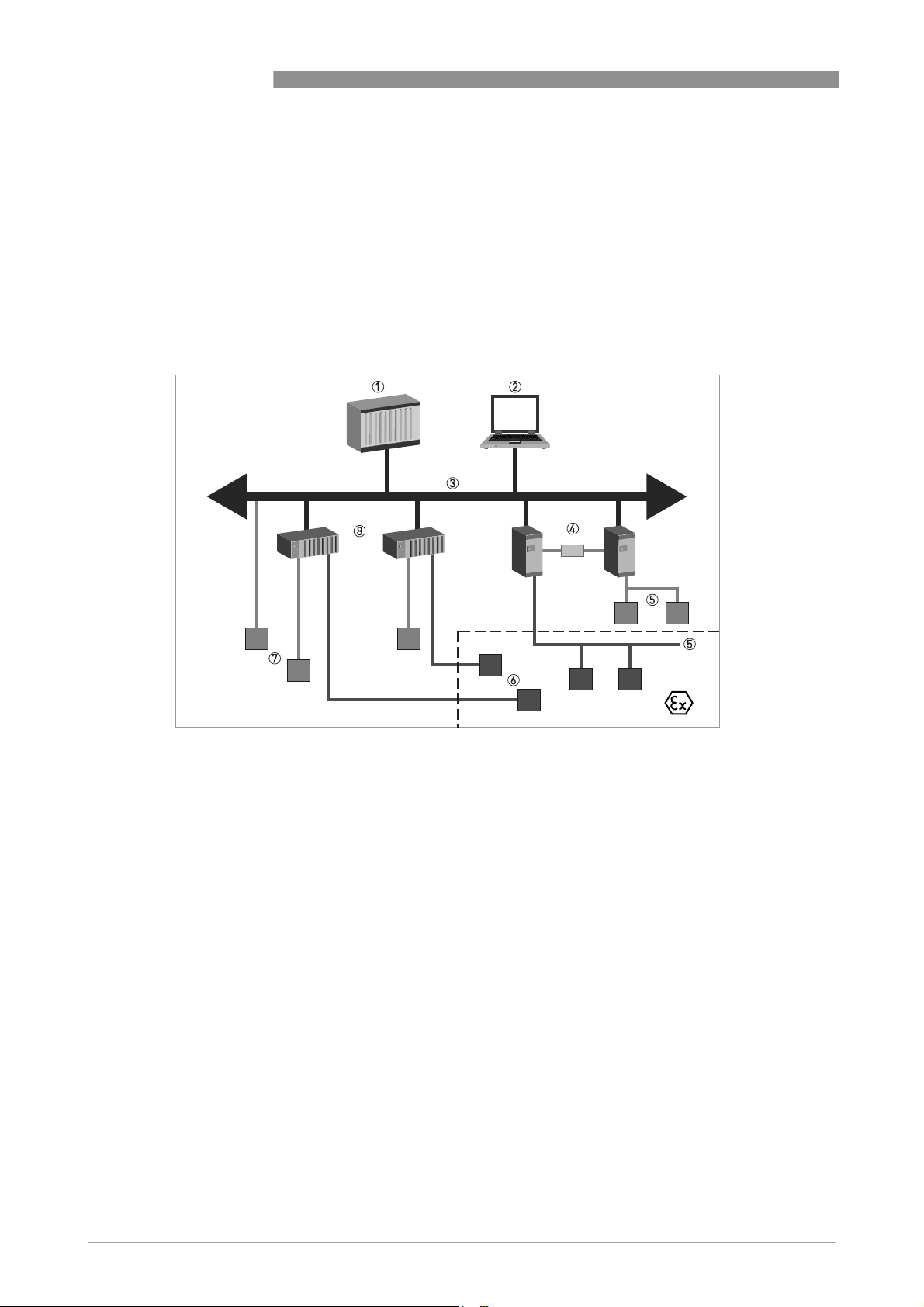
3.2 System configuration of PROFIBUS PA network
The following diagram shows a typical instrumentation with PROFIBUS PA devices with MBP
interface in hazardous and non-hazardous locations, including connections of conventional
devices (e.g. with 4...20 mA signals) in a PROFIBUS network.
As a rule, the PROFIBUS PA segment is connected to a segment coupler which, among other
things, carries out the conversion to the PROFIBUS DP bus line. It should be mentioned that the
segment coupler is normally set to a fixed baud rate on the DP side.
IFC 300
Figure 3-1: PROFIBUS PA network
1 Control system (PLC); class 1 master
2 Engineering or operation control tool; class 2 master
3 PROFIBUS DP network with max. 12 Mbit/s
4 PROFIBUS PA segment coupler DP / PA
5 Device with PROFIBUS PA interface, 31.25 kbit/s
6 HART
7 More devices with 4…20 mA
8 Analogue I/O module
®
device
16
www.krohne.com 02/2011 - 4001086601 - AD IFC 300 PROFIBUS R01 en
Page 17
IFC 300
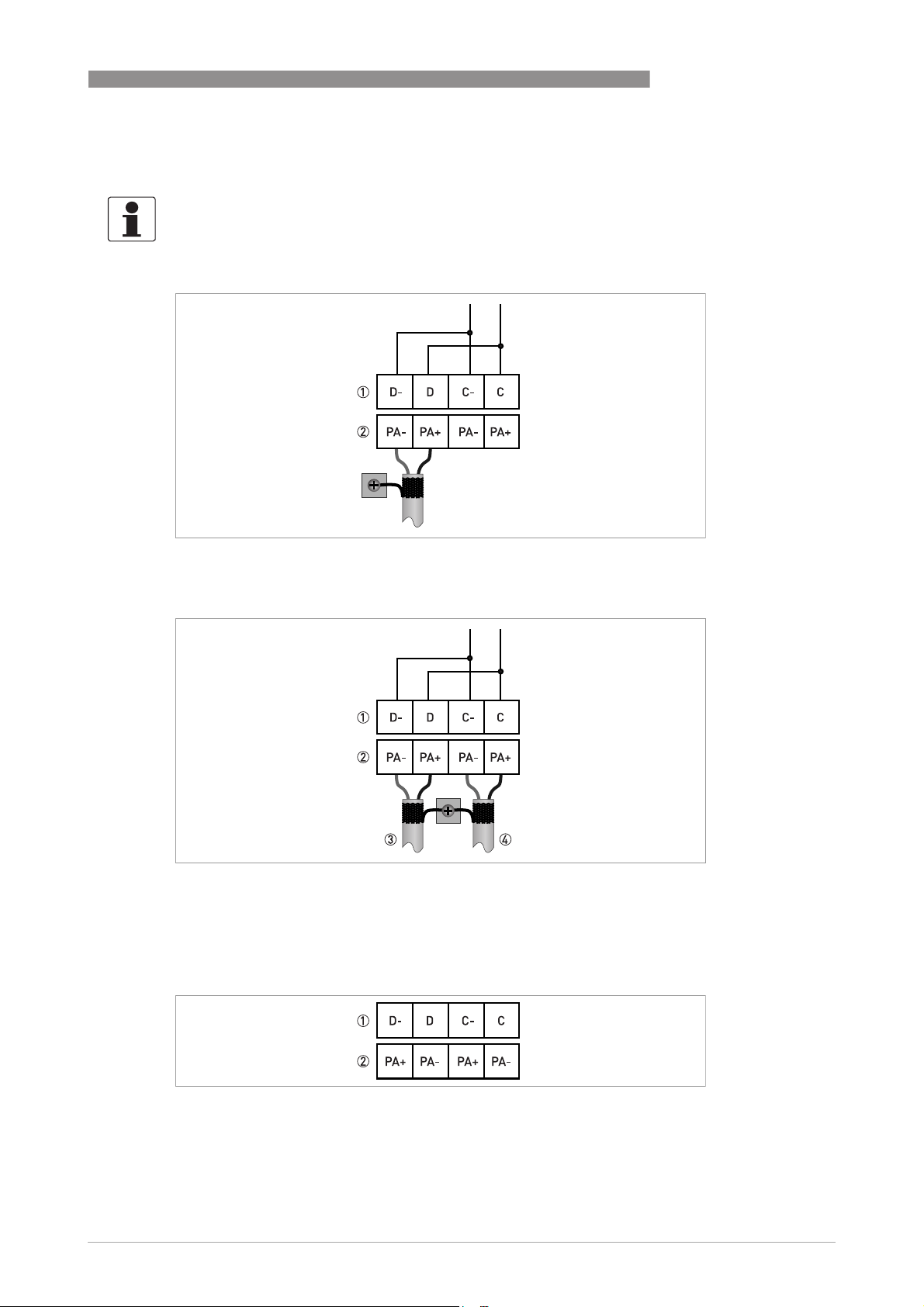
3.3 Electrical connection for PA signal converter
INFORMATION!
For a detailed description of the electrical connections please refer to the standard signal
converter handbook.
External connection with spur
PROFIBUS PA 3
1 Device internal terminal names
2 External bus connections
External connection to a trunk
1 Device internal terminal names
2 External bus connections
3 e.g. incoming data lines
4 e.g. outgoing data lines
Alternative wiring because the current linkage between the device and the PROFIBUS
PA cable is independent of polarity
1 Device internal terminal names
2 External bus connection
www.krohne.com02/2011 - 4001086601 - AD IFC 300 PROFIBUS R01 en
17
Page 18

3 PROFIBUS PA
INFORMATION!
Although the PROFIBUS MBP technology supports power supply via the PROFIBUS line the
"signal converter PROFIBUS MBP interface" will operate only if the additional power supply for
the device is connected / available.
For a detailed description please check the signal converter handbook. Refer also to the
PROFIBUS PA user and installation guideline (Version 2.2, February 2003 PNO order no. 2.092).
3.4 Technical data
Hardware
Type PROFIBUS RS485 interface according to IEC 61158-2 with
Connection Independent of polarity at electrical connection
Base current 10.5 mA
FDE Yes, separate fault disconnection electronics provided (FDE = Fault
Fault current 6 mA (fault current = max. continuous current – base current)
Starting current <12 mA
Ex approval Ex ia IIC or Ex ib IIC/IIB, FISCO Device
IFC 300
31.25 kbits/s; voltage mode
Disconnection Electronics)
For detailed information refer to standard product documentation.
Software
GSD GSD file on CD-ROM or from internet site
Device profile PA Profile compact class B, V 3.0
Address range 0…126 (default 126)
0…125 via PROFIBUS service set_slave_add
0…126 via local display
126 via factory_reset = 2712
Local control Local display and operator interface at device
SAPs 2 x MS1 SAPs – acyclic interface to PLC
3 x MS2 SAPs – the number of MS2 Service Access Points is typically
equal to the maximum number of master class 2 tools
Function blocks 1 x TB = Transducer Block: contains the parameters and functions
defined in PA Profile 3.0
1 x PB = Physical Block: contains the parameters defined in PA
Profile 3.0
5 x AI = Analog Input Blocks: contains the parameters defined in PA
Profile 3.0
3 x TOT = Totalizer Function Blocks: contains the parameters defined
in PA Profile 3.0
18
www.krohne.com 02/2011 - 4001086601 - AD IFC 300 PROFIBUS R01 en
Page 19

IFC 300
3.5 GSD files for the data transfer
A PROFIBUS GSD ZIP file (e.g. GSD-31777813.zip; including both all GSD files and additional data
files) you can get on a CD ROM or can be downloaded from the internet. The GSD file contains
information that will be needed for project planning of the PROFIBUS communication network.
The relevant data files (e.g. _ _ _ _ .bmp / _ _ _ _ .dib) must be loaded into the bus configuration
system/master system before start-up of the bus system.
3.5.1 Cyclic data exchange
During network configuration the user has to define which function block outputs of the signal
converter should be transferred cyclically to the master. Network configuration will be done
using one of the GSD files described before. The order of transmission of a function block always
remains the same even if a function block is defined as an "Empty" block (if so, no function block
output data will be sent to the master and all function block outputs following the empty block
output data will be sent to the master and all function block outputs following the empty block
output data will be sent to the master and all function block outputs following the empty block output data will be sent to the master and all function block outputs following the empty block
will move up one position)
will move up one position).
will move up one position)will move up one position)
3.5.2 Ident.-No. supported
PROFIBUS PA 3
(if so, no function block
(if so, no function block (if so, no function block
The signal converter with PROFIBUS MBP interface is based on PROFIBUS PA Profile V 3.0. The
device supports three Ident-No.:
• Ident-No. "4501hex" belongs to the GSD file KR024501.GSD and YP024501.GSD and includes
the complete functionality of the electromagnetic flowmeter.
• The application of the manufacturer independent Ident-No. "9740hex" (GSD file
"PA039740.GSD") provides interchangeability of devices, i.e. an exchange of electromagnetic
flowmeters of different vendors.
• Ident-No. "F401hex"
For detailed information refer to
as replacement for older signal converter IFC 090 PA
Please follow the instructions in the manual of the host supplier when installing the GSD File you
need and the additional files (_ _ _ _ .bmp and _ _ _ _ .dib) into the PLC.
Signal converter IFC 300 PROFIBUS PA with MBP interface
on page 23.
INFORMATION!
If separated by the bus configuration system the device entry of the PROFIBUS MBP interface
with PA Profile 3.0 will be located within the slave family PROFIBUS PA.
www.krohne.com02/2011 - 4001086601 - AD IFC 300 PROFIBUS R01 en
19
Page 20

3 PROFIBUS PA
3.5.3 Manufacturer specific GSD files: KR024501.GSD and YP024501.GSD
The KR024501.GSD file is for use with the standard DP/PA coupler and the YP024501.GSD file is
for use with the transparent DP/PA coupler SK2/SK3 of Pepperl & Fuchs (up to 12 MBaud on the
DP segment).
INFORMATION!
For devices with MBP interface there are always two types of GSD files in our GSD compilation:
•
One standard GSD file for a standard DP/PA segment coupler with file name: "KR0….GSD"
•
One special GSD file specific for the segment coupler SK2/SK3 of Pepperl & Fuchs with file
…
name: "YP0
It should be noted that both GSD files support device functionality as described below:
.GSD"
IFC 300
Block
number
1 Volume Flow AI-FB
2 Volume Totalizer Totalizer-FB
3 Volume Totalizer Totalizer-FB
4 Mass Totalizer Totalizer-FB kg
5 Mass Flow AI-FB kg/s
6 Speed Flow AI-FB m/s
7 Coil Temperature AI-FB K
8 Conductivity AI-FB S/m
X Electronic Temperature AI-FB °C
X Supply
Default configuration
Function block output: value and
status
(internal supply voltage for the
PROFIBUS interface)
KR024501.GSD
YP024501.GSD
Ident-No. 4501
AI-FB V
Default
unit
m3/h
3
m
3
m
• AI: Analog Input Function Block
• FB: Function Block
• X: Block number 1, 5, 6, 7 or 8
There will be two additional output values available by changing the function block channel
parameters of the above mentioned "Analog Input Function Blocks".
20
There are separate settings to select the units for local display and PROFIBUS. Modifications of
the units of the display will have no effect on the data transferred via PROFIBUS. A master class
2 tool is required to modify the units for PROFIBUS transfer.
www.krohne.com 02/2011 - 4001086601 - AD IFC 300 PROFIBUS R01 en
Page 21

IFC 300
PROFIBUS PA 3
INFORMATION!
During network configuration the user has to define which function block outputs of the signal
converter should be transferred cyclically to the master. This is performed by a bus
configuration tool (e.g. "HW- Config" for PC-S7 from Siemens). This tool offers specific functions
as follows:
1. It is possible to configure an "Empty" block (the code of an "Empty" block is defined as 0x00) on
each block number. This implies: no data are transmitted in the cyclic data telegram for this
block.
2. There is NO "Totalizer (TOT)" function block allowed on block position 1, 5, 6, 7 and 8! On these
positions, only an "Analog Input (AI)" function block or an "Empty" block is allowed!
–
(Note: All codes supported by "Analog Input (AI)" - and "Totalizer (TOT)"
be found in the corresponding GSD files.)
3. There is NO "Analog Input (AI)" function block allowed on block position 2, 3 and 4! On these
positions, only a "Totalizer (TOT)" function block or an "Empty" block is allowed!
4. There is a choice of 7 different totalizer functions, which can be allocated to the blocks 2, 3
and/or 4.
Definition of totalizer functions
Total cyclic transfer of the totalizer value with status to the master
SetTot + Total cyclic transfer of the totalizer value with status to the master + cyclic
control data from master to the device via the parameter SetTot
ModeTot + Total cyclic transfer of the totalizer value with status to the master + cyclic
control data from master to the device via the parameter ModeTot
SetTot + ModeTot + Total cyclic transfer of the totalizer value with status to the master + cyclic
control data from master to the device via the parameters SetTot and
ModeTot (in the given order)
SetTot cyclic control data from master to the device via the parameter
SetTot
ModeTot cyclic control data from master to the device via the parameter
ModeTot
SetTot + ModeTot cyclic control data from master to the device via the parameters
SetTot and ModeTot (in the given order)
function blocks will
www.krohne.com02/2011 - 4001086601 - AD IFC 300 PROFIBUS R01 en
21
Page 22

3 PROFIBUS PA
Both, the Byte SetTot and ModeTot are cyclically sent from the Master to the device if these bytes
are inserted as output data via the PLC configurator. The meaning of these control bytes are as
follows:
Function of control bytes
SetTot
SetTot
SetTotSetTot
SetTot = 0 Totalizer is totalizing.
SetTot = 1 Totalizer will be reset to 0 and stays at 0 until SetTot is switched back
SetTot = 2 Totalizer is set to the value defined by PresetTot. PresetTot can be
SetTot > 2 Not allowed. Value is ignored; totalizer remains in its last valid
ModeTot
ModeTot
ModeTotModeTot
ModeTot = 0 Totalizer totalizes positive and negative values.
ModeTot = 1 Totalizes only positive values.
ModeTot = 2 Totalizes only negative values.
ModeTot = 3 Totalizer is stopped, no totalization will be done.
ModeTot = 248 Totalizes all values as positive, negative values will be multiplied with
ModeTot = 249 Totalizes all values as negative, positive values will be multiplied with
IFC 300
again to 0. If the value of SetTot changes from "1" to "0" the totalizer
starts counting from 0.
written via an acyclic master (totalizer in block 2 = Slot 2 Index 32;
totalizer in block 3 = Slot 3 Index 32; totalizer in block 4 = Slot 4 Index
32). If the value of SetTot changes from "2" to "0" the totalizer starts
counting from the current value defined by PresetTot.
setting.
-1.0.
-1.0.
All other values of ModeTot not allowed. Value is ignored; totalizer remains in its last valid
setting.
The standard block configuration may be changed by the customer but using the default settings
is highly recommended. If the standard block configuration should be changed by the customer
an acyclic master tool or the device display menu must be used to change the "channel
parameter" value of the block which should be connected to another transducer output value.
3.5.4 Profile specific GSD file: PA139740.GSD
The functionality of the profile specific GSD file is limited. This GSD file includes only two blocks:
Block
number
1 Volume Flow AI-FB
2 Volume Totalizer Totalizer-FB
The device has to be switched from full functionality to interchangeable basic configuration by
using one of both a master class 2 tool (IDENT_NUMBER_SELECTOR: Slot 0, Index 40; change
byte value to 0) or the device display menu. In the next step, the device has to be configured using
the PA039740.GSD file.
Standard configuration
Function block output value
PA139740.GSD
Ident-No. 9740
Default
unit
m3/h
3
m
22
www.krohne.com 02/2011 - 4001086601 - AD IFC 300 PROFIBUS R01 en
Page 23

IFC 300
PROFIBUS PA 3
3.5.5 Using the display menu to distinguish the current revision of the device (PA)
Use the display to open the Fct. B3.5 or C5.8.2 of the signal converter. You will get the following
information:
• KROHNE Ident.-No. (of the assembled PROFIBUS PCB)
• Software revision (of the PROFIBUS software)
• Date of production (of the PROFIBUS device)
3.6 Signal converter IFC 300 PROFIBUS PA with MBP interface as
replacement for older signal converter IFC 090 PA
3.6.1 Ident.-No. supported
Ident.-No. "F401hex":
Ident.-No. "F401hex": This Ident.-No. supports a compatibility mode concerning the cyclic data
Ident.-No. "F401hex":Ident.-No. "F401hex":
transfer (cyclic measurement values and diagnosis) if the IFC300 with PROFIBUS MBP interface
will be used for replacement of an "IFC090PA". It is not
configuration. Communication functions are restricted to those functions supported by IFC090
converters. Take care to set the "IFC300 PROFIBUS MBP interface" parameters in a way to get
the same behaviour as of "IFC090PA" concerning calculation of measuring values and totalizers
(this has to be done manually).
not necessary to adapt the PLC
notnot
3.6.2 Manufacturer specific GSD files (PA): KROHF401.GSD and YP01F401.GSD for the
older signal converter IFC090 with PROFIBUS MBP interface
The PROFIBUS signal converter with MBP Interface operating in the IFC090 compatibility mode
ensures operation with a PLC system with software parameters based on the IFC090PA. This
option is important for those customers who do not want to change the parameters in the PLC
software after having replaced the IFC090PA by an IFC300 with PROFIBUS MBP interface. The
existing GSD files of the IFC090PA ("KROHF401.GSD" or "YP01F401.GSD") can still be used.
In this application, the compatibility mode of the IFC300 with PROFIBUS MBP interface has to be
selected (display menu D2.9 - Identification No. -> choose IFC090); some other entries have to be
performed in a next step.
The overall situation is described using the following example: Consider an "IFC090PA" standard
configuration based on IFS…FLUX* flow sensor and "IFC090PA" flow signal converter. Consider
the following two options for replacements (IFS ….FLUX = IFS flow sensor compliant with
IFC090PA):
1. The IFC090PA flow signal converter will be replaced by an IFC300 PROFIBUS MBP interface
flow signal converter. The IFS …FLUX flow sensor is kept.
2. In addition to 1., also the IFS …FLUX flow sensor will be replaced by an OPTIFLUX flow sensor.
Options for flow
sensor installation:
Option 1.: IFS...FLUX
Option 2.: OPTIFLUX
IFC 300 PROFIBUS signal
converter with MBP
→
interface →
device
software
PROFIBUS
PA software
Integration into the
PLC via
a) IFC090PA.GSD
b) IFC300(MBP).GSD
PLC
PROFIBUS PA parameter set
→
in the Ctrl software of the
PLC
a) no change
b) change
www.krohne.com02/2011 - 4001086601 - AD IFC 300 PROFIBUS R01 en
23
Page 24

3 PROFIBUS PA
For both replacements 1. and 2., there are 2 options how to deal with the GSDs. In order to
provide communication between "IFC300 with PROFIBUS MBP interface" and the PLC, you may -
in principle – use the GSD of the "IFC090PA" ("KROHF401.GSD" or "YP01F401.GSD") and
–alternatively - the GSD of the "IFC300 with PROFIBUS MBP interface" ("KR024501.GSD" or
"YP024501.GSD").
IFC 300
However, both sets of GSDs, when applied, do not
do not provide the same level of functionality in the
do notdo not
PLC. The available PROFIBUS functionality of the "IFC300 with PROFIBUS MBP interface" in the
PLC as function of installed flow sensor and GSD used for integration into the PLC is as follows:
Installed flow sensor Integration into the PLC via
IFC090PA.GSD
KROHF401.GSD
IFC300 with PROFIBUS MBP
interface GSD
KR024501.GSD
IFS…FLUX flow sensor
(Option 1.)
OPTIFLUX flow sensor (Option 2.) "IFC090PA" profile 2 functionality "IFC300 with PROFIBUS MBP
How to deal with the PA
parameter set in the PLC Ctrl
software
"IFC090PA" profile 2 functionality "IFC300 with PROFIBUS MBP
The "IFC090PA" parameter set
for the PLC Ctrl software can be
used as existing in the PLC
interface" functionality (some
"IFC300 with PROFIBUS MBP
interface" self-test functions not
available)
interface" functionality
The "IFC090PA" parameter set
for the Ctrl software has to be
adapted with reference to the
interface of "IFC300 with
PROFIBUS MBP interface"
If the GSDs of the "IFC090PA" ("KROHF401.GSD" or "YP01F401.GSD") are used…
• The IFC090PA parameter set for the PLC control software will be maintained, i.e. there is no
adaptation needed with reference to the replaced interface of the IFC300 with PROFIBUS
MBP interface.
• In this usage of the GSD the PA Profile 2.0
replacements, i.e. it is not possible to reset the PA totalizer via the PLC.
PA Profile 2.0 functionality is provided in the PLC for both
PA Profile 2.0PA Profile 2.0
24
If the GSD of "IFC300 with PROFIBUS MBP interface” (KR024501.GSD or
YP024501.GSD) is used…
• The IFC090PA parameter set for the PLC control software has to be adapted with reference to
the IFC300 PROFIBUS MPB interface.
• In this usage of the GSD the PA Profile 3.0
of the "IFC300 with PROFIBUS MBP interface" are being made available.
PA Profile 3.0 functionality is provided and all diagnostic features
PA Profile 3.0PA Profile 3.0
www.krohne.com 02/2011 - 4001086601 - AD IFC 300 PROFIBUS R01 en
Page 25

IFC 300
APPLICATION PROFILE 4
4.1 Function blocks
The PROFIBUS MBP interface is based on the PROFIBUS PA Profile Version 3.0 and supports the
following blocks:
• 1 physical block.
This block contains the parameters defined in PA Profile 3.0.
• 1 transducer block for electromagnetic flow devices.
This block provides the parameters and functions defined in PA Profile 3.0.
• 5 Analog Input (AI) function blocks.
As default: Volume Flow / Mass Flow / Speed Flow / Coil Temperature / Conductivity.
• 3 totalizer (TOT) function blocks.
As default the first two totalizers will totalize volume and the third one will totalize mass.
4.2 Data structure of function block output values
The data structure of function block outputs consists of 5 bytes: a 4 byte float value (Float Format
according IEEE Standard 754 Short Real Number) followed by a 1 byte status value. If all 8
function block outputs have been configured (see above), 40 bytes will be transmitted.
4.2.1 Float value
Example of float format
Byte n Byte n+1
Bit7 Bit6 Bit7 Bit6
VZ
Byte n+2 Byte n+3
Bit7 Bit7
-82-9
2
Mantissa Mantissa
Example (binary): 40 F0 00 00 (hex) = 0100 0000 1111 0000 0000 0000 0000 0000
Formula:
Formula:
Formula:Formula:
value = (-1)
value = (-1)
value = 1 * 4 * (1 + 0.5 + 0.25 + 0.125)
value = 7.5
7
6
5
4
3
2
1
0
2
2
2
2
2
2
2
2
Exponent Mantissa
-102-112-122-132-142-152-162-172-182-192-202-212-222-23
2
VZ
(Exponent – 127)
0
* 2
* 2
(129 – 127)
* (1 + Mantissa)
* (1 + 2-1 + 2-2 + 2-3)
-12-22-32-4
2
-52-62-7
2
www.krohne.com02/2011 - 4001086601 - AD IFC 300 PROFIBUS R01 en
25
Page 26

4 APPLICATION PROFILE
4.2.2 Status value
The meanings of the status byte (unsigned integer) are described in the following tables.
Quality Quality substatus Limits
Gr Gr QS QS QS QS Qu Qu
7
6
5
4
2
2
2
0 0 = bad
0 1 = uncertain
1 0 = good (Non Cascade)
1 1 = good (Cascade) - not supported
Status = bad
Quality Quality substatus Limits
Gr Gr QS QS QS QS Qu Qu
7
6
2
0 0 0 0 0 0 = non-specific
0 0 0 0 0 1 = configuration error
0 0 0 0 1 0 = not connected
0 0 0 0 1 1 = device failure
0 0 0 1 0 0 = sensor failure
0 0 0 1 0 1 = no communication (last usable value)
0 0 0 1 1 0 = no communication (no usable value)
0 0 0 1 1 1 = out of service
5
2
2
3
2
2
4
3
2
2
IFC 300
2
1
2
2
2
0
2
2
1
0
2
2
Status = uncertain
Quality Quality substatus Limits
Gr Gr QS QS QS QS Qu Qu
7
6
5
4
3
2
1
2
2
2
2
2
2
0 1 0 0 0 0 = non-specific
0 1 0 0 0 1 = last usable value
0 1 0 0 1 0 = substitute-set
0 1 0 0 1 1 = initial value
0 1 0 1 0 0 = sensor conversion not accurate
0 1 0 1 0 1 = engineering unit violation (unit not in the valid set)
0 1 0 1 1 0 = sub-normal
0 1 0 1 1 1 = configuration error
0 1 1 0 0 0 = simulated value
0
2
2
26
www.krohne.com 02/2011 - 4001086601 - AD IFC 300 PROFIBUS R01 en
Page 27

IFC 300
APPLICATION PROFILE 4
Status = good (Non Cascade)
Quality Quality substatus Limits
Gr Gr QS QS QS QS Qu Qu
7
6
5
4
3
2
1
2
2
2
2
2
2
1 0 0 0 0 0 = ok
1 0 0 0 0 1 = update event
1 0 0 0 1 0 = active advisory alarm (priority < 8)
1 0 0 0 1 1 = active advisory alarm (priority > 8)
1 0 0 1 0 0 = unacknowledged update event
1 0 0 1 0 1 = unacknowledged advisory alarm
1 0 0 1 1 0 = unacknowledged critical alarm
1 0 1 0 0 0 = initiate fail safe
1 0 1 0 0 1 = maintenance required
Status = Limits
0
2
2
Quality Quality substatus Limits
Gr Gr QS QS QS QS Qu Qu
7
6
5
4
3
2
1
2
2
2
2
2
2
0
2
2
0 0 = ok
0 1 = low limited
1 0 = high limited
1 1 = constant
Check the first two quality bits in order to get the quality information of the measurement value:
• Good (Non Cascade):
Good (Non Cascade): function block output value is ok and can be used without restrictions
Good (Non Cascade):Good (Non Cascade):
• Good (Cascade):
Good (Cascade): will not be supported, because it is not applicable for the device
Good (Cascade):Good (Cascade):
• Uncertain:
Uncertain: function block output value can be used but the accuracy can not be guaranteed
Uncertain:Uncertain:
(e.g. function block outputs value has been frozen or A/D converter is saturated or out of
range)
• Bad:
Bad: function block output value is bad - don’t use it for process control!
Bad:Bad:
The "Quality-Substatus" and "Limit" bits will be used for further diagnostics or limit checking.
INFORMATION!
The status should be monitored because a number will be transmitted even if the status of the
measurement value is bad or uncertain. This is the only way to check the quality of the
transmitted measurement values.
www.krohne.com02/2011 - 4001086601 - AD IFC 300 PROFIBUS R01 en
27
Page 28

4 APPLICATION PROFILE
4.3 Diagnosis parameter
4.3.1 Diagnosis
Parameter DIAGNOSIS will contain detailed information of the device, bitwise coded. More than
one message possible at once (as below-mentioned). If MSB of byte 4 is set to 1 than more
diagnose information is available in the DIAGNOSIS_EXTENSION parameter.
The manufacturer specific parameter "DIAGNOSIS_EXTENSION" will contain bitwise coded
more detailed information of the internal status conditions and error conditions of the
PROFIBUS device.
The corresponding GSD file will contain all messages supported by this device - have a look at
the UNIT_DIAG_BIT(i) definitions.
4.3.2 DIAGNOSIS (if "Classic Status" and "Diagnosis" selected)
IFC 300
Octet number
Bit number
Subparameter
1 0 DIA_HW_ELECTR 0 Hardware failure electronics
1 DIA_HW_MECH 0 Hardware failure mechanics
2 DIA_TEMP_MOTOR 0 Motor temperature too high
3 DIA_TEMP_ELECTR 0 Electronic temperature too high
4 DIA_MEM_CHKSUM 0 Memory error
5 DIA_MEASUREMENT 0 Measurement failure
6 DIA_NOT_INIT 0 Device not initialized
7 DIA_INIT_ERR 0 Device initialization failed
2 0 DIA_ZERO_ERR 0 Zero point error
1 DIA_SUPPLY 0 Power supply failed
2 DIA_CONF_INVAL 0 Configuration invalid
3 DIA_WARMSTART A 0 Restart (warmstart)
4 DIA_COLDSTART A 0 Coldstart (with default data)
5 DIA_MAINTENANCE R 0 Maintenance required
6 DIA_CHARACT R 0 Characteristics invalid
7 IDENT_NUMBER_VIOLATION R 0 Ident. No. violation:
Indication type
Default value
Description
Set to 1 if the Ident_Number of the running cyclic
data transfer and the value of physical block
IDENT_NUMBER_SELECTOR parameter are
different
28
www.krohne.com 02/2011 - 4001086601 - AD IFC 300 PROFIBUS R01 en
Page 29

IFC 300
APPLICATION PROFILE 4
Octet number
Bit number
Subparameter
3 0 Reserved 0 Reserved for use by PNO
1 Reserved 0 Reserved for use by PNO
2 Reserved 0 Reserved for use by PNO
3 Reserved 0 Reserved for use by PNO
4 Reserved 0 Reserved for use by PNO
5 Reserved 0 Reserved for use by PNO
6 Reserved 0 Reserved for use by PNO
7 Reserved 0 Reserved for use by PNO
4 0 Reserved 0 Reserved for use by PNO
1 Reserved 0 Reserved for use by PNO
2 Reserved 0 Reserved for use by PNO
3 Reserved 0 Reserved for use by PNO
4 Reserved 0 Reserved for use by PNO
5 Reserved 0 Reserved for use by PNO
6 Reserved 0 Reserved for use by PNO
7 EXTENSION_AVAILABLE 0 Extension available:
Indication type
Default value
Description
More diagnose information available in the
Diagnosis_Extension parameter (if available)
www.krohne.com02/2011 - 4001086601 - AD IFC 300 PROFIBUS R01 en
29
Page 30

4 APPLICATION PROFILE
4.3.3 DIAGNOSIS_EXTENSION (if "Classic Status" and "Diagnosis" selected)
Octet number
Bit number
Subparameter
1 0 ADC_ELEC_TEMPERATURE (S) electronic temperature
1 ADC_GAIN_ERROR (S) gain error
2 ADC_F_FREQ_TOO_HIGH (S) field frequency too high
3 Reserved
4 ADC_COIL_TEMPERATURE (S) coil temperature
5 ADC_F_CURR_DEVIATION (S) field current deviation
6 ADC_F_COIL_BRIDGED (S) field coil bridged
7 ADC_F_COIL_BROKEN (S) field coil broken
2 0 ADC_ELECTRODE_NOISE (S) electrode noise
1 ADC_FLOW_PROFILE (S) flow profile
2 ADC_LINEARITY (S) linearity
3 ADC_ELECTRODE_SYM (S) electrode symmetry
4 Reserved
5 Reserved
6 ADC_PIPE_NOT_FULL (S) pipe not full
7 ADC_EMPTY_PIPE_0 (S) empty pipe (Uncertain)
3 0 Reserved
1 ADC_FIELD_FREQ_HIGH (F) field frequency too high
2 ADC_EMPTY_PIPE_1 (F) empty pipe (Application Error)
3 ADC_DC_OFFSET (F) DC Offset
4 Reserved
5 ADC_FIELD_CURR_LOCAL (F) field current local
6 ADC_SENSOR_LOCAL (F) sensor local
7 ADC_SENSOR_GLOBAL (F) sensor global
4 0 ADC_FLOW_EXCEED_LIM0 (F) flow exceeding limit
1 ADC_FLOW_EXCEED_LIM1 (F) flow exceeding limit
2 MEAS_AVAILABLE_NO (I) measurement value not available
3 POWER ON ERROR (I) power fail
4 ADC_TEST_SENSOR (C) test sensor
5 ADC_WARNING_W1 (S) uncertain measurement
6 ADC_WARNING_W2 (F) application error
7 ADC_SENSOR_ELECTRONIC (F) sensor electronic
Comment*
(F) field current local
(F) field current local(F) field current local
(F) sensor local
(F) sensor local(F) sensor local
(F) sensor global
(F) sensor global(F) sensor global
(F) sensor electronic
(F) sensor electronic(F) sensor electronic
IFC 300
30
www.krohne.com 02/2011 - 4001086601 - AD IFC 300 PROFIBUS R01 en
Page 31

IFC 300
APPLICATION PROFILE 4
Octet number
Bit number
Subparameter
5 0 BM_TEST_ACTIV (C) checks in progress (global)
1 BM_MEAS_UNC (S) uncertain measurement (global)
2 BM_APP_ERROR (F) application error (global)
3 BM_DEV_ERROR (F) error in device (global)
4 NO_BASIC_DEVICE_COM (F) int. communication timeout
5 PARA UPDATE ERROR (F) parameter update error
6 PARA UPDATE IN PROGRESS update in progress
7 ERROR_CPU_CM (F) CPU failure
6 0 ERROR_EEPROM (F) EEPROM failure
1 CYCLE_EEPROM (S) EEPROM cycle overflow
2 ERROR_CPU_MEM (F) CPU Memory failure
3 ERROR_RAM_EXT (F) ext. RAM failure
4 ERROR_FRAM (F) FRAM failure
5 CYCLE_FRAM (S) FRAM cycle overflow
6 ERROR_FLASH_EXT (F) external Flash failure
7 ERROR_SPC4 (F) SPC4 failure
Comment*
(F) error in device (global)
(F) error in device (global)(F) error in device (global)
(F) int. communication timeout
(F) int. communication timeout(F) int. communication timeout
(F) parameter update error
(F) parameter update error(F) parameter update error
(F) CPU failure
(F) CPU failure(F) CPU failure
(F) EEPROM failure
(F) EEPROM failure(F) EEPROM failure
(F) CPU Memory failure
(F) CPU Memory failure(F) CPU Memory failure
(F) ext. RAM failure
(F) ext. RAM failure(F) ext. RAM failure
(F) FRAM failure
(F) FRAM failure(F) FRAM failure
(F) external Flash failure
(F) external Flash failure(F) external Flash failure
(F) SPC4 failure
(F) SPC4 failure(F) SPC4 failure
*: for a more detailed description of the above-mentioned subparameters please check the
signal converter handbook (section: Status messages and diagnostic information)
(F): Device Error
(F): Device Error
(F): Device Error(F): Device Error
(F): Application Error
(S): Uncertain measurement / measurement out of specification
(C): Simulation of the measured value
(I): Information
4.3.4 Mapping of DIAGNOSIS_EXTENSION bits into DIAGNOSIS bits
How to read this table:
If e.g. an ADC_EMPTY_PIPE_0 error has been detected by the device itself the below-mentioned
DIAGNOSIS_EXTENSION bits will be set:
• DIAGNOSIS_EXTENSION (Octet 2 / Bit 7): ADC_EMPTY_PIPE_0
• DIAGNOSIS_EXTENSION (Octet 4 / Bit 5): ADC_WARNING_W1
• DIAGNOSIS_EXTENSION (Octet 5 / Bit 1): BM_MEAS_UNC
These bits will be mapped to the below-mentioned DIAGNOSIS bits (which will be set
additionally):
• DIAGNOSIS (Octet 1 / Bit 5): DIA_MEASUREMENT
• DIAGNOSIS (Octet 4 / Bit 7): EXTENSION_AVAILABLE
www.krohne.com02/2011 - 4001086601 - AD IFC 300 PROFIBUS R01 en
31
Page 32

4 APPLICATION PROFILE
IFC 300
DIAGNOSIS_EXTENSION DIAGNOSIS
1 2 3 ... 4
0 1 2 3 4 5 6 7 0 1 2 3 4 5 6 7 0 ... 6 7
Octet number
Bit number
Subparameter
1 0 ADC_ELEC_TEMPERATURE X X
1 ADC_GAIN_ERROR X X
2 ADC_F_FREQ_TOO_HIGH X X
3 Reserved
4 ADC_COIL_TEMPERATURE X X
5 ADC_F_CURR_DEVIATION X X
6 ADC_F_COIL_BRIDGED X X
7 ADC_F_COIL_BROKEN X X
2 0 ADC_ELECTRODE_NOISE X X
1 ADC_FLOW_PROFILE X X
2 ADC_LINEARITY X X
3 ADC_ELECTRODE_SYM X X
4 Reserved
5 Reserved
6 ADC_PIPE_NOT_FULL X X
7 ADC_EMPTY_PIPE_0 X X
3 0 Reserved
1 ADC_FIELD_FREQ_HIGH X X
2 ADC_EMPTY_PIPE_1 X X
3 ADC_DC_OFFSET X X
4 Reserved
5 ADC_FIELD_CURR_LOCAL XXXX X
6 ADC_SENSOR_LOCAL XXXX X
7 ADC_SENSOR_GLOBAL XXXX X
DIA_HW_ELECTR
DIA_HW_MECH
DIA_TEMP_MOTOR
DIA_TEMP_ELECTR
DIA_MEM_CHKSUM
DIA_MEASUREMENT
DIA_NOT_INIT
DIA_INIT_ERR
DIA_ZERO_ERR
DIA_SUPPLY
DIA_CONF_INVAL
DIA_WARMSTART
DIA_COLDSTART
DIA_MAINTENANCE
DIA_CHARACT
IDENT_NUMBER_Violation
Reserved
...
Reserved
EXTENSION_AVAILABLE
32
www.krohne.com 02/2011 - 4001086601 - AD IFC 300 PROFIBUS R01 en
Page 33

IFC 300
APPLICATION PROFILE 4
DIAGNOSIS_EXTENSION DIAGNOSIS
1 2 3 ... 4
0 1 2 3 4 5 6 7 0 1 2 3 4 5 6 7 0 ... 6 7
Octet number
Bit number
Subparameter
4 0 ADC_FLOW_EXCEED_LIM0 X X
1 ADC_FLOW_EXCEED_LIM1 X X
2 MEAS_AVAILABLE_NO X
3 POWER ON ERROR X
4 ADC_TEST_SENSOR X
5 ADC_WARNING_W1 X X
6 ADC_WARNING_W2 X X
7 ADC_SENSOR_ELECTRONIC XXXX X
5 0 BM_TEST_ACTIV X
1 BM_MEAS_UNC X X
2 BM_APP_ERROR X X
3 BM_DEV_ERROR X X
4 NO_BASIC_DEVICE_COM X X
5 PARA UPDATE ERROR X X
6 PARA UPDATE IN
PROGRESS
7 ERROR_CPU_CM XXXX X
6 0 ERROR_EEPROM XXXX X
1 CYCLE_EEPROM X X
2 ERROR_CPU_MEM XXXX X
3 ERROR_RAM_EXT XXXX X
4 ERROR_FRAM XXXX X
5 CYCLE_FRAM X X
6 ERROR_FLASH_EXT XXXX X
7 ERROR_SPC4 XXXX X
DIA_HW_ELECTR
DIA_HW_MECH
DIA_TEMP_MOTOR
DIA_TEMP_ELECTR
DIA_MEM_CHKSUM
DIA_MEASUREMENT
DIA_NOT_INIT
DIA_INIT_ERR
DIA_ZERO_ERR
DIA_SUPPLY
DIA_CONF_INVAL
DIA_WARMSTART
DIA_COLDSTART
DIA_MAINTENANCE
DIA_CHARACT
IDENT_NUMBER_Violation
Reserved
...
Reserved
X X
EXTENSION_AVAILABLE
X :Ext_Diag (Bit 3 of Station_Status_1) will be set too!
X :Corresponding DIAGNOSIS bits is set to 1 if status occured
www.krohne.com02/2011 - 4001086601 - AD IFC 300 PROFIBUS R01 en
33
Page 34

5 PROFIBUS SETTINGS
IFC 300
For a detailed description of the menus and functions refer to the standard product
documentation of the signal converter. Some special settings concerning the PROFIBUS
features are easily operated via the local display menu (refer to the following sections).
5.1 Menu A, quick setup
No. Function Settings / descriptions
A2 Tag
A2 Tag Tag descriptor of the physical block of the PROFIBUS module will be
A3 reset
A3 reset -
A3.1 reset errors This menu function can be used to reset all errors that are not removed
The following reset menus for the totalizer are only available, if the quick access has been activated in the menu "setup
> device > quick setup". Each totalizer can be activated for quick access independently.
A3.2 FB2 totalizer 1 For PROFIBUS devices: The totalizer can be reset to zero in this menu.
A3.3 FB3 totalizer 2
A3.4 FB4 totalizer 3
displayed. The Tag descriptor provides an application specific reference to
the blocks. It will be assigned by the user of the device. The Tag descriptor is
an octet string (a visible string will be preferred) consisting of 32 byte. The
first 21 characters will be displayed only!
automatically (power fail, totalizer overflow)
reset? Select: no / yes
no: Exit the function.
yes: Resets the errors and exits the function.
A4 station address
A4 station address Selects the address of the device at the PROFIBUS interface.
The PROFIBUS address can also be changed using the PROFIBUS service
"set_slave_add". The input range is 0...125 according to the PROFIBUS
specification. Address 126 is the default address and cannot be set via the
PROFIBUS service "set_slave_add" - use menu instead to reset to default
address.
5.2 Menu B, test
No. Function Settings / descriptions
B3 information
B3.5 PROFIBUS Available if there is a PROFIBUS interface in existence; displays the
following mentioned information about the PROFIBUS interface:
Ident No. / software revision no. of the PROFIBUS software / production date
34
www.krohne.com 02/2011 - 4001086601 - AD IFC 300 PROFIBUS R01 en
Page 35

IFC 300
PROFIBUS SETTINGS 5
5.3 Menu C, setup
No. Function Settings / descriptions
C3 I/O totalizer
C3.1 FB2 totalizer 1 Set function of totalizer
C3.2 FB3 totalizer 2
C3.3 FB4 totalizer 3
C3..1 funct. of totalizer Select:
C3..2 measurement Selection of the measurement for totalizer
C3..3 preset value Predefines a threshold (using high low limit value of the totalizer affected;
C3..4 reset totalizer The current value of the totalizer can be set to zero.
C3..5 error behaviour Defines the behaviour of this function block in case of errors.
C3..6 information Serial no. of the I/O board, software version no. and production date of the
stands for 1, 2, 3 (= totalizer 1, 2, 3)
sum totalizer (counts positive and negative values) /
+totalizer (counts only the positive values) /
-totalizer (counts only the negative values) /
hold totalizer (totalizer is stopped, no counting) /
all as positive (neg. input will be multiplied with -1.0) /
all as negative (pos. values will be multiplied with 1.0)
Select: volume flow / mass flow (not
the THRESHOLD bit will be set in the long status information bytes of the
interface if the actual value of the totalizer is outside these limits. This can
be also used for a status output.
Select: no / yes (reset totalizer 1…3)
Select: hold meas. value / ignore error / stop totalizer
hold meas. value:
hold meas. value: Totalization is continued based on the last incoming value
hold meas. value:hold meas. value:
with good status before the first occurrence of bad status.
ignore error:
ignore error: Totalization is continued using the input values despite the bad
ignore error:ignore error:
status. The status is ignored.
stop totalizer:
stop totalizer: Totalization is stopped during occurrence of bad status of
stop totalizer:stop totalizer:
incoming values.
circuit board will be displayed
not valid for PF (partly filled))
notnot
C4 I/O PROFIBUS
C4 I/O PROFIBUS Using the menu functions mentioned below you will be able to control
C4.1 FB1 analog inp. There are 5 analog input blocks.
C4.2 FB5 analog inp.
C4.3 FB6 analog inp.
C4.4 FB7 analog inp.
C4.5 FB8 analog inp.
C4..1 measurement Select measurement for the analog input blocks:
C4..2 time constant Set time constant for this function block ().
basically the five analog input blocks of this PROFIBUS device. These five
menus are identical so they are grouped together and their functions are
described in one go.
stands for the 5 analog input blocks: FB1 ( = 1), FB5 ( = 2), FB6 ( = 3),
FB7 ( = 4) and FB8 ( = 5)
flow speed / volume flow / mass flow (not
temperature / conductivity (not
(capacitive)) / temperature (electronic temperature) / supply (internal supply
voltage for PROFIBUS interface)
www.krohne.com02/2011 - 4001086601 - AD IFC 300 PROFIBUS R01 en
not valid for PF (partly filled) and CAP
notnot
not valid for PF (partly filled)) / coil
notnot
35
Page 36

5 PROFIBUS SETTINGS
No. Function Settings / descriptions
C4..3 error behaviour Defines the behaviour of this function block in case of errors.
Select: hold value / ignore error / replace value
hold value:
hold value: Last valid OUT value stored will be used as OUT value.
hold value:hold value:
ignore error:
ignore error: OUT has the wrong calculated value and status "Bad" as
ignore error:ignore error:
calculated.
replace value:
replace value: The "replacement value" will be used as OUT value.
replace value:replace value:
C4..4 replacement value Available, if the error behaviour "replace value" is selected. Defines the
C5 device
C5.1.1 Tag Tag descriptor of the physical block of the PROFIBUS module will be
C5.3 1. meas. page Setting of the measurement for the 1st measuring page.
C5.3.2 measurement 1.line Specify measurement for 1st line.
C5.3.8 measurement 2.line Specify measurement of 2nd line (only available if this 2.line is activated)
C5.3.10 measurement 3.line Specify measurement of 3rd line (only available if this 3.line is activated)
C5.4 2. meas. page Setting of the measurement for the second measuring page.
C5.4.1
C5.4.3
C5.4.5
C5.4.2
C5.4.4
C5.4.6
C5.6 special functions -
C5.6.1 reset errors This menu function can be used to reset all errors that are not removed
C5.6.2 save settings Save current settings.
measurement 1.line
measurement 2.line
measurement 3.line
format 1.line
format 2.line
format 3.line
value that replaces the measured value at this function block in case of an
error.
displayed. The Tag descriptor provides an application specific reference to
the blocks. It will be assigned by the user of the device. The Tag descriptor is
an octet string (a visible string will be preferred) consisting of 32 byte. The
first 21 characters will be displayed only!
Select: volume flow / mass flow (not
value / flow speed / coil temperature / conductivity (not
filled)) and CAP (capacitive)) / level (only
Select: bar graph (for the measurement selected in the first line) / volume
flow / mass flow (not
speed / FB2 totalizer 1 / FB3 totalizer 2 / FB4 totalizer 3 / conductivity (not
valid for PF (partly filled) and CAP (capacitive)) / coil temperature / operating
hours / level (only
Select: volume flow / mass flow (not
value / flow speed / coil temperature / conductivity (not
filled) and CAP (capacitive)) / FB2 totalizer 1 / FB3 totalizer 2 /
FB4 totalizer 3 / operating hours / level (only
current input A / current input B
For PROFIBUS devices this page shows only the PROFIBUS values
FB1…FB8.
Select the measurement of the 1st, 2nd and 3rd line:
FB1 analog inp. / FB2 totalizer 1 / FB3 totalizer 2 / FB4 totalizer 3 / FB6
analog inp. / FB7 analog inp. / FB8 analog inp.
Fixed number of digits after the decimal point or automatic, where the
number of digits is automatically adjusted to the available space.
automatically (power fail, totalizer overflow)
reset? Select: no / yes
Select: break (exit function without saving) / backup 1 (save in storage
location 1) / backup 2 (save in storage location 2)
Query: continue copy? (cannot be undone)
Select: no (exit function without saving) / yes (copy current settings to
storage backup 1 or backup 2)
not valid for PF (partly filled)) / diagnosis value / flow
not not
only valid for PF (partly filled))
onlyonly
not valid for PF (partly filled)) / diagnosis
notnot
only valid for PF (partly filled))
onlyonly
not valid for PF (partly filled)) / diagnosis
notnot
only valid for PF (partly filled)) /
onlyonly
not valid for PF (partly
notnot
not valid for PF (partly
notnot
IFC 300
not
not not
36
www.krohne.com 02/2011 - 4001086601 - AD IFC 300 PROFIBUS R01 en
Page 37

IFC 300
No. Function Settings / descriptions
PROFIBUS SETTINGS 5
C5.6.3 load settings Load saved settings.
C5.8 physical block This menu is only available, if a PROFIBUS interface is present.
C5.8.1 station address Selects the PROFIBUS station address of the device.
C5.8.2 information Available if there is a PROFIBUS interface in existence; displays the
C5.8.3 diag. extension Content of the PROFIBUS diagnosis extension is displayed.
C5.8.4 diag. extension 2 Content of the additional, internal diagnosis stored is displayed.
C5.8.6 diag. extension h h = history
C5.9 quick setup Activate quick access in quick setup menu; default setting: quick setup is
C5.9.1 reset totalizer 1 The reset can be activated in the "quick setup" to get a quick access of the
C5.9.2 reset totalizer 2
C5.9.3 reset totalizer 3
Select: break (exit function without loading) / factory settings (load in state
as delivered) / backup 1 (load data from storage location 1) / backup 2 (load
data from storage location 2) / load sensor data (factory settings of
calibration data)
Query: continue copy? (cannot be undone)
Select: no (exit the function without saving) / yes (load data from the selected
storage location)
The PROFIBUS address can also be changed using the PROFIBUS service
"set_slave_add". The input range is 0...125 according to the PROFIBUS
specification. Address 126 is the default address and cannot be set via the
PROFIBUS service "set_slave_add" - use menu instead to reset to default
address.
following mentioned information about the PROFIBUS interface:
Ident No. / software revision no. of the PROFIBUS software / production date
Content of the PROFIBUS diagnosis extension is displayed.
Shows diagnosis information of all diagnosis bits, which are set again since
the last delete.
active (yes)
Select: yes (switched on) / no (switched off)
function.
Select: yes (activated) / no (switched off)
www.krohne.com02/2011 - 4001086601 - AD IFC 300 PROFIBUS R01 en
37
Page 38

5 PROFIBUS SETTINGS
IFC 300
5.4 Menu D, service
This menu is protected. You will need to use the service password to gain access.
No. Function Settings / descriptions
D2 service parameters In this menu all functions related to different data sets can be found.
D2.1 cold start Resetting of the signal converter can be done here but all changes up to this
D2.2 save factory data Copies the actual data into the factory setting; this overwrites the factory
D2.9 Identification No. Sets different device modes for the cyclic communication of the PROFIBUS
D2.10 PB cold start Initiates a PROFIBUS cold start.
D2.12 diag. extension h h = history
point are automatically stored and cannot be discarded.
Select: no (terminates the function) / yes (performs the reset and leaves the
setting mode)
settings done during calibration!
Query: save settings? (cannot be undone)
Select: break (exit function without saving) / factory settings (saves the
settings as factory settings)
Query: continue copy? (cannot be undone)
Select: no (exit function without saving) / yes (copy current settings to the
selected storage location)
interface.
Select: signal converter (the normal settings incl. all manufacturer specific
parameters are supported) / profile (uses only the profile defined functions,
no extras, only profile specific parameters are supported) / IFC090
(compatibility mode)
During a PROFIBUS cold start nearly all parameter values of the whole
device will be set to their default values (Exceptions are the PROFIBUS
address and the identification No.). The cold start will be carried out without
disconnecting an already established connection to a PROFIBUS master
system.
Query: reset? (to default values) = cold start begins
Select: no (terminates the function) / yes (PROFIBUS cold start will be
carried out at once; the setting mode is terminated)
Delete the stored history.
Query: reset? = reset history to 0)
Select: no (no change) / yes (all saved data are deleted)
38
www.krohne.com 02/2011 - 4001086601 - AD IFC 300 PROFIBUS R01 en
Page 39

IFC 300
NOTES 6
www.krohne.com02/2011 - 4001086601 - AD IFC 300 PROFIBUS R01 en
39
Page 40

KROHNE product overview
• Electromagnetic flowmeters
• Variable area flowmeters
• Ultrasonic flowmeters
• Mass flowmeters
• Vortex flowmeters
• Flow controllers
• Level meters
• Temperature meters
• Pressure meters
• Analysis products
• Measuring systems for the oil and gas industry
• Measuring systems for sea-going tankers
Head Office KROHNE Messtechnik GmbH
Ludwig-Krohne-Str. 5
D-47058 Duisburg (Germany)
Tel.:+49 (0)203 301 0
Fax:+49 (0)203 301 10389
info@krohne.de
© KROHNE 02/2011 - 4001086601 - AD IFC 300 PROFIBUS R01 en - Subject to change without notice.
The current list of all KROHNE contacts and addresses can be found at:
www.krohne.com
 Loading...