

Page 1

Supplementary instructions
Supplementary instructions
ESK4... ...
ESK4... ...
ESK4... ... ESK4... ...
Supplementary instructionsSupplementary instructions
Electronic signal output
Equipment category II 2G, EPL Gb
© KROHNE 05/2014 - 4001078702 MA ESK4 Ex II2G AD R02-en
Page 2

CONTENTS
ESK4... ...
1 Safety instructions 3
1.1 General notes ................................................................................................................... 3
1.2 EC conformity ................................................................................................................... 3
1.3 Safety instructions............................................................................................................ 3
2 Device description 4
2.1 Device description ............................................................................................................ 4
2.2 Description code............................................................................................................... 4
2.3 Marking............................................................................................................................. 4
2.4 Equipment category .........................................................................................................5
2.5 Protection types................................................................................................................ 5
2.6 Ambient temperature / temperature classes.................................................................. 5
2.7 Electrical data................................................................................................................... 6
3 Installation 7
3.1 Installation........................................................................................................................ 7
3.2 Special conditions............................................................................................................. 7
4 Electrical connections 8
4.1 General notes ................................................................................................................... 8
4.2 Power supply .................................................................................................................... 8
5 Operation 9
5.1 Start-up............................................................................................................................. 9
5.2 Operation .......................................................................................................................... 9
6 Service 10
6.1 Maintenance ................................................................................................................... 10
6.2 Dismantling .................................................................................................................... 10
7 Notes 11
2
www.krohne.com 05/2014 - 4001078702 MA ESK4 Ex II2G AD R02-en
Page 3

ESK4... ...
1.1 General notes
These additional instructions apply to explosion-protected versions of the ESK4... electronic
signal output with the designation II 2 G. They complete the installation and operation
instructions for the non-explosion protected versions.
The information given in these Instructions contains only the data relevant to Category 2
explosion protection. The technical details given in the installation and operation instructions for
the non-explosion protected versions apply unchanged unless excluded or superseded by these
instructions.
1.2 EC conformity
The manufacturer declares with the EC declaration of conformity on his own responsibility
conformity with the protection goals of directive 94/9/EC for use in hazardous areas with gas.
Conformity with harmonised standards was checked
in accordance with EN 60079-0:2012 und EN 60079-11:2012.
The EC declaration of conformity is based on the EC type examination certificate of the
Physikalisch Technische Bundesanstalt (PTB):
SAFETY INSTRUCTIONS 1
The "X" after the certificate number refers to special conditions for safe use of the device, which
have been listed in these instructions.
If needed the EC type test certificate can be downloaded from the manufacturer's website.
1.3 Safety instructions
Assembly, installation, start-up and maintenance may only be performed by personnel trained in
explosion protection!
CAUTION!
Should operating conditions and locations require the observance of further standards,
guidelines and laws, this is the responsibility of the operator and/or those commissioned by him.
PTB 10 ATEX 2021 X
PTB 10 ATEX 2021 X
PTB 10 ATEX 2021 XPTB 10 ATEX 2021 X
www.krohne.com05/2014 - 4001078702 MA ESK4 Ex II2G AD R02-en
3
Page 4
2 DEVICE DESCRIPTION
2.1 Device description
ESK4... electronic signal outputs serve to determine the position of magnetic encoders. They are
designed for installation in M40 type indicators and are usually used in measuring devices to
measure the volume flow and level of flammable and non-flammable gases and liquids.
The analogue current signal (4-20 mA) with superimposed HART® communication signal and
optional switching outputs and bus connection modules for connection to the Foundation
Fieldbus FF or Profibus PA is available as the output signal.
2.2 Description code
The safety description code * consists of the following elements:
1 EEEElectronic SSSSignal output KKKKrohne
2 Version of the signal output
4444 - Analogue signal output 4-20mA with HART signal
4-I/O
4-I/O - Switch output with counter
4-I/O4-I/O
4-FF
4-FF - Foundation Fieldbus connection module
4-FF4-FF
4-PA
4-PA - Profibus PA connection module
4-PA4-PA
3 Marking without influence on the explosion safety protection
ESK4... ...
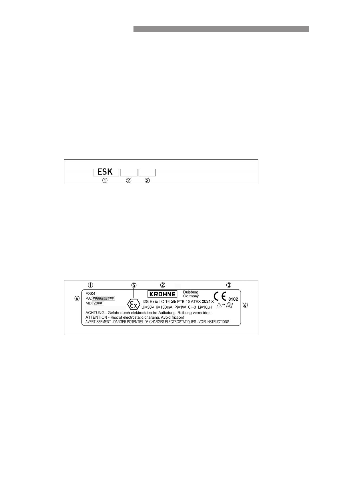
2.3 Marking
The marking of the module is on the housing, where the following identification plate can be
found.
1 Device type
2 Manufacturer
3 Notified ATEX body
4 Serial number
5 Ex-data acc. to PTB 10 ATEX 2021 X
6 Note manual
4
www.krohne.com 05/2014 - 4001078702 MA ESK4 Ex II2G AD R02-en
Page 5

ESK4... ...
2.4 Equipment category
The electronic signal outputs are designed in category II 2 G or EPL Gb according to EN 60079-0
and EN 60079-11 for use in zone 1.
2.5 Protection types
The electronic signal output is designed with protection type intrinsic safety, protection level "ia"
acc. to EN 60079-11.
DEVICE DESCRIPTION 2
The marking acc. to ATEX is: II 2G Ex ia IIC T6 Gb
The marking contains the following information:
The marking contains the following information:
The marking contains the following information:The marking contains the following information:
II
II Explosion protection, group II
IIII
2222 Equipment category 2
GGGG Gas explosion protection
Ex ia
Ex ia Intrinsically safe, level of protection "ia"
Ex iaEx ia
IIC
IIC Suitable for gas groups IIC, IIB and IIA
IICIIC
T6
T6 Suitable for temperature classes T6...T1
T6T6
Gb
Gb EPL, suitable for zone 1
GbGb
II 2G Ex ia IIC T6 Gb
II 2G Ex ia IIC T6 GbII 2G Ex ia IIC T6 Gb
2.6 Ambient temperature / temperature classes
Depending on the version and the temperature class, the electronic signal outputs are approved
for the following ambient temperatures.
ESK4... permissible ambient temperatures
Type
Signal Output
Temperature class Ambient temperature in
[°C] [°F]
ESK4 ...
ESK4-I/O
ESK4-FF
ESK4-PA
T6 -40...+60 -40...+140
T5 -40...+75 -40...+167
T4...T1 -40...+85 -40...+185
T6 -40...+55 -40...+131
T5 -40...+70 -40...+158
T4...T1 -40...+85 -40...+185
www.krohne.com05/2014 - 4001078702 MA ESK4 Ex II2G AD R02-en
5
Page 6

2 DEVICE DESCRIPTION
2.7 Electrical data
The connection may only be made using separately certified intrinsically safe isolating amplifiers
or zener barriers with the following maximum values per circuit:
ESK4... ... electrical values
ESK4... ...
Type
Terminals Maximum value per intrinsically safe circuit
Signal Output
U
i
ESK4 ... 11, 12 30 V 130 mA 1 W 0nF 10 µH
ESK4-I/O 1, 2, 3 or
4, 5, 6 or
7, 8
ESK4-FF / ESK4-PA D, D- 24 V 380 mA 5.32 W 0nF 0 µH
30 V 130 mA 1 W 10 nF 0 µH
I
i
FISCO FIELD DEVICE
P
i
C
i
L
i
The connector behind the cutout on the ESK4... module cover connects internal intrinsically safe
circuits. Only certified modules of type ESK4 I/O, ESK4 FF or ESK4 PA may be connected. The
additional connector on the ESK 4I/O module connects the optional display as an internal
intrinsically safe circuit.
6
www.krohne.com 05/2014 - 4001078702 MA ESK4 Ex II2G AD R02-en
Page 7

ESK4... ...
3.1 Installation
Installation and setup must be carried out according to the applicable installation standards (e.g.
EN 60079-14) by qualified personnel trained in explosion protection. The information given in the
Installation and Operation Instructions and the Supplementary Installation and Operation
Instructions must always be observed.
Electronic signal outputs must be installed so that
• There are no external forces acting on the housing.
• The nameplate is clearly visible.
• It can be operated from a location with secure footing.
CAUTION!
The manufacturer is not liable for any damage resulting from improper use or use other than the
intended purpose.
3.2 Special conditions
INSTALLATION 3
Housing protection
Electronic signal outputs are to be protected against external influences by a housing (min.
IP20).
Electrostatic charge
The plastic housing of the electronic signal output may be electrostatically charged. Take
appropriate measures to ensure that no charge is applied to the surface of the housing during
installation and operation.
ESK4-FF and ESK4-PA connection
When operating the ESK4-FF or ESK4-PA module for connection to intrinsically safe bus
systems, the ESK4... module may not be powered separately. The ESK4... module is fed by the
flat ribbon cable from the modules ESK4-FF or ESK4-PA.
www.krohne.com05/2014 - 4001078702 MA ESK4 Ex II2G AD R02-en
7
Page 8

4 ELECTRICAL CONNECTIONS
4.1 General notes
The electrical connection of the intrinsically safe signal circuit with protection level "ia" to the
modules ESK4... , ESK4 FF and ESK4 PA is independent of polarity. The connection of the ESK4
I/O module is polarity sensitive. The connection to all modules is made by colour-coded
pluggable connection terminals. The colour coding of the terminals must be observed. The
permissible maximum values of the separate circuits (electrical data) must be observed.
The connecting cables must be selected according to prevailing installation standards (e.g.
EN 60079-14).. The connecting cables must be fixed and laid so they are sufficiently protected
against damage.
All cores that are not used must be securely connected to the ground potential of the hazardous
area or carefully insulated against each other and against ground (test voltage ≥ 500 V
4.2 Power supply
Electronic signal outputs do not require a separate power supply. The required supply is
provided via the 4...20 mA current output or bus-connection.
ESK4... ...
).
eff
8
www.krohne.com 05/2014 - 4001078702 MA ESK4 Ex II2G AD R02-en
Page 9

ESK4... ...
5.1 Start-up
Start-up is only permitted when the electronic signal output:
• is correctly installed in a housing and connected.
• has been checked for the proper state with regard to its installation and connection
requirements.
The user of the system must have it checked before start-up in compliance with the national
regulations for checks before startup.
5.2 Operation
The electronic signal output may be parameterized via the HART® communication and the
button may be operated during operation.
OPERATION 5
www.krohne.com05/2014 - 4001078702 MA ESK4 Ex II2G AD R02-en
9
Page 10

6 SERVICE
6.1 Maintenance
Maintenance work of a safety-relevant nature within the meaning of explosion protection may
only be carried out by the manufacturer, his authorised representative or under the supervision
of authorised inspectors.
For systems in hazardous areas, regular tests are required in order to maintain the proper
condition.
The following checks are recommended:
• checking the housing, connection terminals and feed lines for corrosion and/or damage.
Close the housing following any maintenance work on the electronic signal output.
6.2 Dismantling
Replacing the electronic signal output
Due to the modular design of the electronic signal output, it is possible to replace a module with
an identical spare part in accordance with safety guidelines.
ESK4... ...
If at all possible, the meter should be electrically isolated before removing and replacing the
indicator. If that is not possible, the basic conditions for intrinsic safety (e.g. no grounding or
connection of different intrinsically safe circuits to one another) must be observed during
dismantling.
Removal and installation are the responsibility of the operator.
CAUTION!
There may be a loss of measuring accuracy!
10
www.krohne.com 05/2014 - 4001078702 MA ESK4 Ex II2G AD R02-en
Page 11

ESK4... ...
NOTES 7
www.krohne.com05/2014 - 4001078702 MA ESK4 Ex II2G AD R02-en
11
Page 12

KROHNE product overview
• Electromagnetic flowmeters
• Variable area flowmeters
• Ultrasonic flowmeters
• Mass flowmeters
• Vortex flowmeters
• Flow controllers
• Level meters
• Temperature assemblies
• Pressure transmitters
• Analysis products
• Products and systems for the oil & gas industry
• Measuring systems for the marine industry
Head Office KROHNE Messtechnik GmbH
Ludwig-Krohne-Str. 5
47058 Duisburg (Germany)
Tel.:+49 203 301 0
Fax:+49 203 301 103 89
info@krohne.com
© KROHNE 05/2014 - 4001078702 MA ESK4 Ex II2G AD R02-en - Subject to change without notice.
The current list of all KROHNE contacts and addresses can be found at:
www.krohne.com
 Loading...