

Page 1
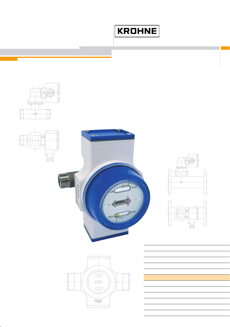
Installation and
operating instructions
DW 181 – 184
Standard, high-temperature,
tropical and ATEX versions
Flow switches
©
KROHNE 01/2006 7.02125.23.00
CMD
Electromagnetic flowmeters
Variable area flowmeters
Mass flowmeters
Ultrasonic flowmeters
Vortex flowmeters
Flow controllers
Level measuring instruments
Pressure and temperature
Heat metering
Communications technology
Switches, counters, displays and recorders
Engineering systems & solutions
Page 2

Table of contents
General advice on safety………………………………………………………………………….. 4
Standards / Approvals…………………………………………………………………………….. 4
Ex safety instructions……………………………………………………………………………… 4
Handling……………………………………………………………………………………………… 4
Product liability and warranty……………………………………………………………………. 5
Items included with supply……………………………………………………………………….. 5
Documentation supplied………………………………………………………………………….. 5
Official approvals and certificates………………………………………………………………. 5
Principle components……………………………………………………………………………... 6
Equipment labels…………………………………………………………………………………… 7
Type code……………………………………………………………………………………………. 8
1 Mechanical Installation……………………………………………………………………… 9
1.1 Positioning the flow switch……………………………………………………………………. 9
1.2 Installation in hazardous areas (Ex applications)………………………………………….. 9
1.3 Connecting the DW 18 to the pipe…………………………………………………………… 9
1.4 Flow direction…………………………………………………………………………………... 9
2 Electrical Connections…………………………………………………………………….. 10
3 Commissioning……………………………………………………………………………… 11
3.1 General notes………………………………………………………………………………… 11
3.2 Adjusting the limit switches - standard and EEx ia flow switch versions………………. 11
3.2.1 Type G indicator……………………………………………………………………………. 11
3.2.2 Type A indicator…………………………………………………………………………..... 12
3.3 Adjusting the limit switches - EEx d flow switch version…………………………………. 12
3.3.1 MS 12/BRX switch…………………………………………………………………………. 12
4 Display………………………………………………………………………………………... 13
4.1 Local Flow indication………………………………………………………………………… 13
4.2 Limit Switches………………………………………………………………………………… 13
4.3 EEx d version…………………………………………………………………………………. 14
4.4 High-temperature version (KROHNE temperature class H3, non-EEx)………………... 15
4.5 Tropical version (non-EEx)………………………………………………………………….. 15
2 Installation and operating instructions DW 181 - 184
Page 3

5 Service………………………………………………………………………………………... 16
5.1 Maintenance………………………………………………………………………………….. 16
5.2 Exploded view of instruments………………………………………………………………. 16
5.3 Spare parts……………………………………………………………………………………. 18
5.4 Inspection procedure………………………………………………………………………… 21
5.4.1 Inspection procedure: measuring assembly…………………………………………….. 21
5.4.2 Inspection procedure: housing (DW181 & DW182 models)…………………………... 21
5.5 Basic servicing procedures………………………………………………………………….. 22
5.5.1 Changing the position of the dial on the type A indicator……………………………… 22
5.5.2 Removing the display assembly: operating faults in the housing DW18x Std /EExia flow
controllers equipped with type G or A indicators……………………………………….. 23
5.5.3 Cleaning the springs or changing the measuring system sub-assembly…………….. 24
5.5.4 Changing gaskets in DW 183 flow controllers…………………………………………. 24
6 Technical Data………………………………………………………………………………. 25
6.1 Flow range table by flow range code………………………………………………………. 28
6.2 Instrument version materials………………………………………………………………... 30
7 Dimensions and Weights………………………………………………………………….. 31
8 Measuring Principle………………………………………………………………………… 36
8.1 Measuring systems…………………………………………………………………………... 36
8.2 DW 183………………………………………………………………………………………... 36
Appendix A: Declaration of conformity: CE………………………………………………….. 37
Appendix B: If you need to return a device for testing or repair to KROHNE…………. 38
Installation and operating instructions DW 181 - 184 3
Page 4
General advice on safety
This manual gives a complete set of instructions for the installation, operation and
maintenance of the standard and ATEX versions of the DW 18 flow switches.
DW 18 flow switches must be used with liquids that do not have any gas pockets.
Special regulations are applicable to the use of equipment in hazardous locations,
and these are described in this booklet. Data is supplied on explosion protection.
Assembly, installation, commissioning and maintenance of equipment in
hazardous areas must only be carried out by qualified personnel with
relevant explosion protection training.
Standards / Approvals
DW 18 flow switches meet the protection requirements of Directive
89/336/EEC in conjunction with EN 50081-1 and EN 50082-2, and Directives
73/23/EEC and 93/68/EEC in conjunction with EN 61010-1, and also bear the
CE symbol.
These instruments, when ordered with the appropriate options, are certified for
use in hazardous locations by the INERIS certification agency under INERIS
03ATEX0045X. They respect the Health & Safety regulations in force by
conforming to EN 50014 (+ A1 & 2), EN 50018, EN 50020, EN50284, EN
50281-1-1 (+ A1) and EN 13463-1.
Ex safety instructions
The DW 18 flow switch series are suitable for monitoring flow of liquid in pipes in hazardous
areas. They may be approved for use in explosive atmospheres of all flammable substances in
Gas Group IIC in Zone 1 and applications requiring Category 2 equipment for EEx d applications
and Gas Group IIC in Zone 0 requiring Category 1 equipment with an intrinsically-safe power
supply for
EEx ia applications.
Ex Equipment Category Definitions
Category 1 G/D – instruments: for intrinsically-safe applications
The signal converter for the limit switch options and the measuring components are located in
hazardous areas requiring instruments qualified as being category 1. The G/D rating states that
the instrument is qualified for gas and dust environments. EEx ia-approved devices must be used
with a certified intrinsically-safe power supply.
Category 2 G/D – instruments: for applications using the EEx d-rated explosion-proof box
The signal converter for the limit switch options and the measuring components are located in
hazardous areas requiring instruments qualified as being category 2. The G/D rating states that
the instrument is qualified for gas and dust environments.
Handling
The device weighs between approx. 2 kg (4.5 lb) and 14 kg (30 lb). Carry using both hands to lift
the device carefully by the tube. If necessary, use lifting gear.
Avoid hard blows, jolts, impacts, etc. when handling the DW 18.
4 Installation and operating instructions DW 181 - 184
Page 5

Product liability and warranty
The DW 18 flow meter is designed solely for measuring the flow rate of liquids without any gas
pocket. Special codes and regulations apply to its use in hazardous areas.
Responsibility as to suitability and intended use of these level gauges rests solely with the user.
Improper installation and operation of our level gauges may lead to loss of warranty.
In addition, the "General conditions of sale", forming the basis of the purchasing contract, are applicable.
If you need to return the level gauge to the manufacturer or supplier, please refer to the information
given in Appendix B.
Items included with supply
The scope of supply encompasses, in the version ordered:
• Flow meter
Documentation supplied
• Installation and operating instructions (this manual) including description of special versions and
functions.
Official approvals and certificates
Application Approved by Instrument version Certification mark
ATEX certification
*This EC-type Examination Certificate is available in KROHNE’s download centre on
http://www.krohne.com/.
INERIS DW 18 TYPE 18. Certificate no.
INERIS 03ATEX0045X*
Installation and operating instructions DW 181 - 184 5
Page 6
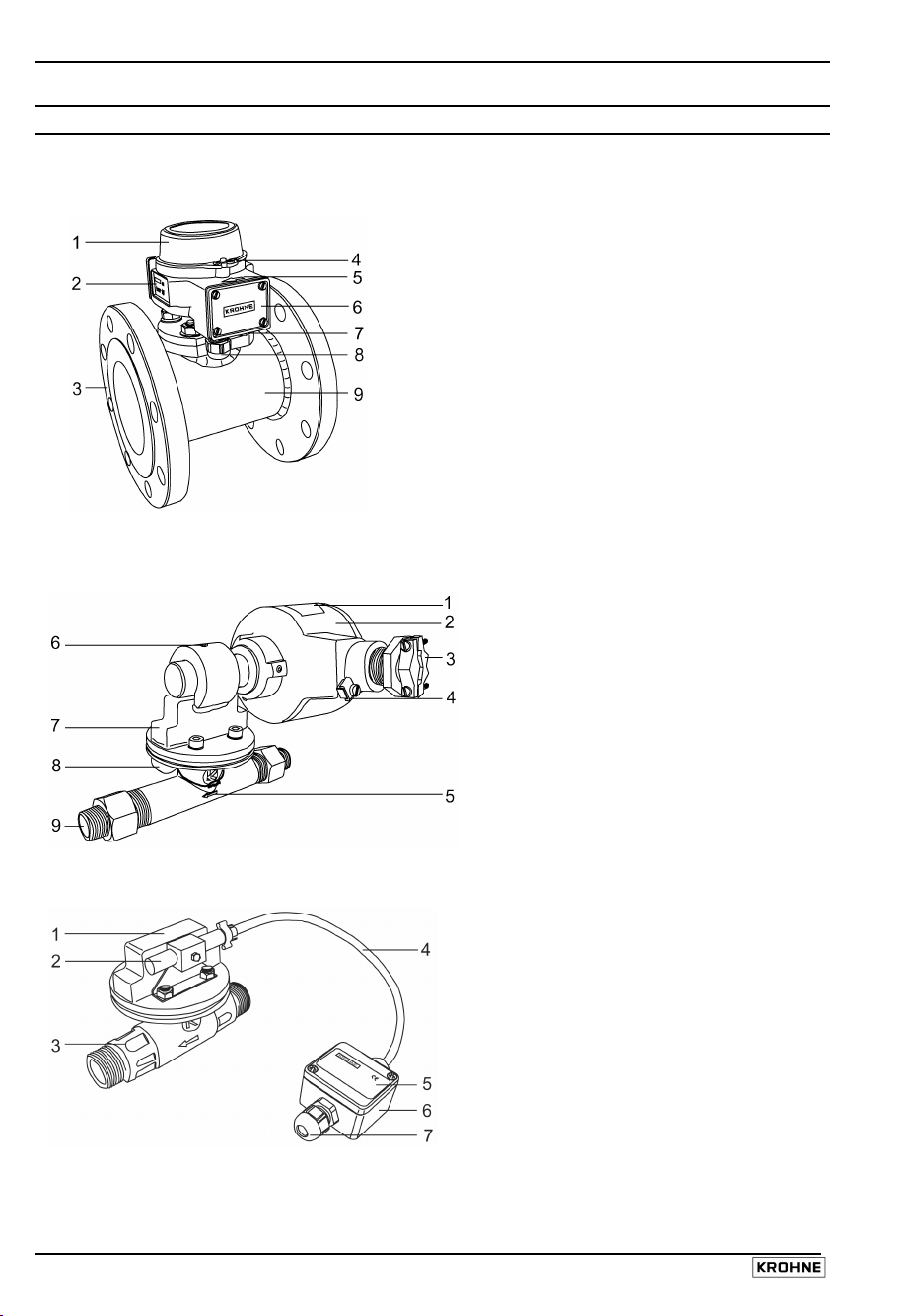
Principle components
DW 18 Standard or EEx ia version
1 Indicator type G (linear scale) or A
(dial)
2 Equipment label*
3 Flange (illustrated) or screwed
connection
4 Indicator cover locking pin
5 Flow direction arrow (DW183/4)
6 Wiring compartment cover
7 Gland (plugged)
8 Cable fitting (PG 13.5)
9 Measuring tube
DW 18 EEx d version
DW 18 HT (H3) version
1 Equipment labels*
2 MS 12/BRX switch housing
3 Cable fitting (to be supplied by the
customer)
4 PE terminal
5 Flow direction arrow (on measuring
tube for DW181/2)
6 Socket set screw for adjusting
switch position
7 Pressure housing
8 Equipment dog-tag (tag no., etc.)
9 Screw-on connection
1 Pressure housing
2 Switch sheathed in a PTFE
cartridge
3 Measuring tube
4 Electric cable in fibre glass
sheathing
5 MS 14 switch information label
6 Wiring box
7 Cable fitting (PG 9)
* Equipment labels shown on next page
6 Installation and operating instructions DW 181 - 184
Page 7
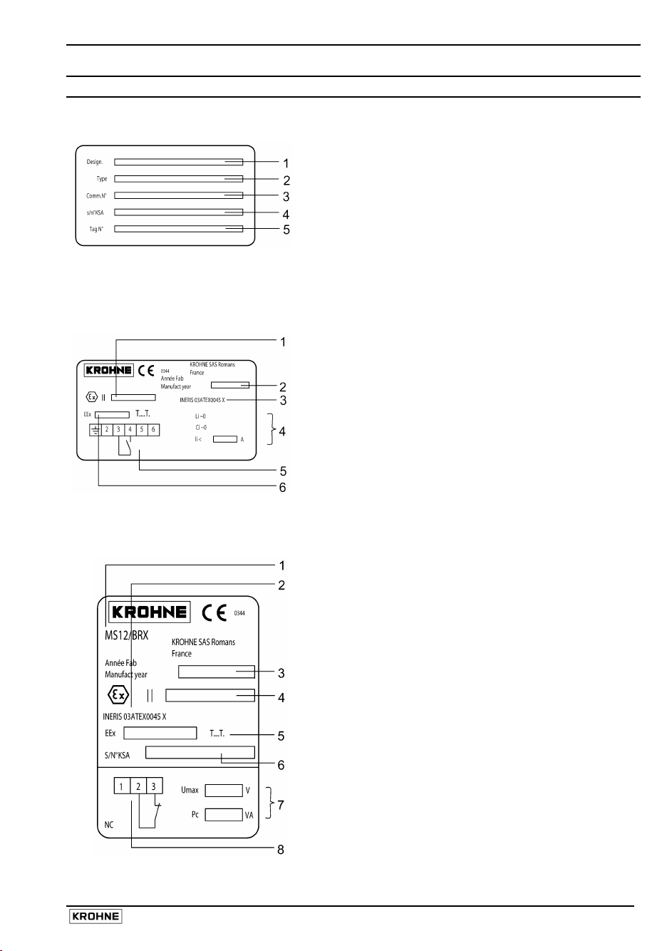
Equipment labels
Standard label (all devices)
EEx ia supplementary information label (e.g. version K1 NO)
EEx d supplementary information label (e.g. version NC)
1 Designation code acc. to order
2 Type code
3 Purchase order number
4 Factory serial number
5 Customer tag number
1 ATEX gas group and equipment
2 Year built
3 ATEX certification code
4 Electrical safety values
5 Wiring diagram
6 Protection concept & gas group +
1
2 ATEX certification code
3 Year built
4 ATEX gas group and equipment
5 Protection concept & gas group +
6 Factory serial number
7 Maximum switching capacity
8 Wiring diagram
options list (e.g.V7BD1...)*
(e.g. DW181/C/011/B/G/KA/N/G1)**
category (e.g. II 1 GD)
sub-div. and temperature class (e.g.
EEx ia IIC T3...T6)
Limit switch code
category (e.g. II 1/2 GD)
sub-div. and temperature class
(e.g. EEx d IIC T3...T6)
* See DW 181-184 Data sheet for a list of order options and designation codes
** See type code definitions on the next page
Installation and operating instructions DW 181 - 184 7
Page 8

Type code
Refer to the standard device label, item 2 on the previous page.
DW . . .
1 2 3 4 5 6 7 8
Type code element Code Code definition
1 Type series 181
2 Measuring system C
3 Code number 011 - 204 See section 7.1: Flow range table for the
4 Material of construction
- see also section 7.2
5 Indicator system G
6 Limit switches K1
7 Application field N
8 Connection G ¾…G2
* Refer to section 9.1
** Bistable.
NO is a “normally open” switch during operation (closed switch when flow is decreasing)
NC is a “normally closed” switch during operation (closed switch when flow is increasing).
/ . / . . . . / . . / . / . . . / . . / . .
182
183
184
E
P
B
RR
R
N
A
K2
KV1
KV2
Ex d
Ex ia
DN15…200
(½”…8”)
For horizontal or vertical pipes, screw
connection G¾…G2, measuring system C or
E*
For horizontal or vertical pipes, flange
connection DN15…65 and ½”…2”-150 lbs,
measuring system C or E*
For horizontal or vertical pipes, flange
connections DN65…200 and 3”…8”-150 lbs,
measuring system P*
For horizontal pipes (DN ≥250 or 10”, mounting
flange DN150 PN16 or 6”-150 lbs, measuring
system P*
Measuring disc in tapered tube
Nozzle with baffle
Baffle in constant diameter pipe
characteristics of each code number.
Bronze
Stainless steel (SS) 316 L
SS 316L measuring tube, steel connection
Steel
Linear scale marks
Dial with flow units
1 NC or 1 NO switch**
1 NC and 1 NO switch**
Amplifier relay: 1 change-over switch**
Amplifier relay: 2 change-over switches**
Normal locations
Hazardous locations
Intrinsically-safe applications
Pipe thread
Flange connection
8 Installation and operating instructions DW 181 - 184
Page 9
1 Mechanical Installation
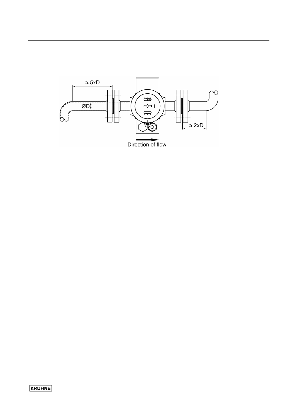
1.1 Positioning the flow switch
No obstacles along the pipe within five diameters (D) upstream and two diameters downstream of
the instrument.
1.2 Installation in hazardous areas (Ex applications)
Read all instructions referring to flow switches in hazardous locations before installation.
Check that the flange, gasket and other materials in contact with the product are compatible. Refer
to the information given on the converter nameplate, the flange markings and specifications given
in the ATEX approval certificate.
1.3 Connecting the DW 18 to the pipe
• Before installation, clean the piping to remove any dust or weld debris.
• Fit the instrument on the pipe with the arrow on the housing pointing in the direction of flow.
• Flange connections: ensure that the gaskets are in place, flange facings are aligned and parallel
and that the bolts have been tightened with the amount of torque specified in European or local (if
outside the E.U.) standards.
1.4 Flow direction
The DW 183 and DW 184 can be installed in any position on the piping. However, the position of
installation and the flow direction must be indicated in the customer order (i.e. up, down, left to right
and right to left) as the weight of the baffle disc is taken into account when calibrating the
instrument. Flow direction must be indicated for DW 181 and DW 182 instruments equipped with
type A indicators.
The DW 184 is used for high-velocity or turbulent flows in pipes with diameters greater than
DN250. A special device, called a stilling well, is immersed in the liquid flow and channels the fluid
through a tube in which the disc moves, secured to the end of a rigid support. This reinforced pivot
enables the flow switch to be used in difficult conditions.
These instruments are only supplied with an index display (indicator type “G”) and switches. They
are not equipped with a graduated dial. The heights of the connection piece indicated for the
production of the mating flange must be respected.
Installation and operating instructions DW 181 - 184 9
Page 10
2 Electrical Connections
Disconnect the power supply before opening the housing
• The electrical connection
conforms to the standard
EN61010-1, protection
class 1 (for aluminium
housing) or class 2 (for
PVC housing), voltage
category III, and
interference degree 2.
• The DW range conforms
to EMC directives NF EN
50 081.1 (Emission) and
NF EN 50 082.2
(Immunity).
• It is obligatory to have a
switching or circuit
breaking device, following
present regulations. The
devices should completely
isolate the unit and be
easily accessible, close to
the unit.
• Both the live (L) and
neutral (N) wires should
be protected by a fuse
(4…6.3 A Time Lag).
During the wiring
procedure the ground wire
should always be
connected first (relevant
only for aluminium
housing).
• EEx ia versions must be
used with a certified
intrinsically-safe power
supply.
N.B. Use of the unit
outside the specifications
detailed in this manual can
compromise the safety
measures designed into the
unit. Always disconnect the
power supply before
accessing the terminals.
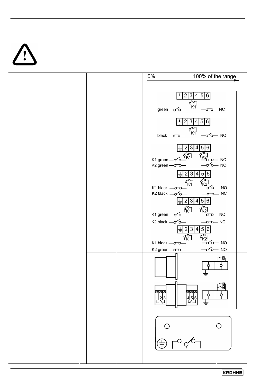
Number
of
switches
1
2
1
1
K1
+
K2
Switch
types
Type
K1
Type
K1
Type
K2
Type
K2
Type
K2
Type
K2
Type
KV1
Type
KV2
Change
over
(SPDT)
Limit switch adjustable over entire range
A
B
C
D
E
F
G
H
10 Installation and operating instructions DW 181 - 184
Page 11
3 Commissioning
3.1 General notes
The flow switch is delivered pre-calibrated and ready for use. Open the valves slowly when starting
operation.
3.2 Adjusting the limit switches - standard and EEx ia flow switch versions
The limit switches can be adjusted individually over the entire measuring range. To adjust, remove
the locking pin securing the cap and remove the cap.
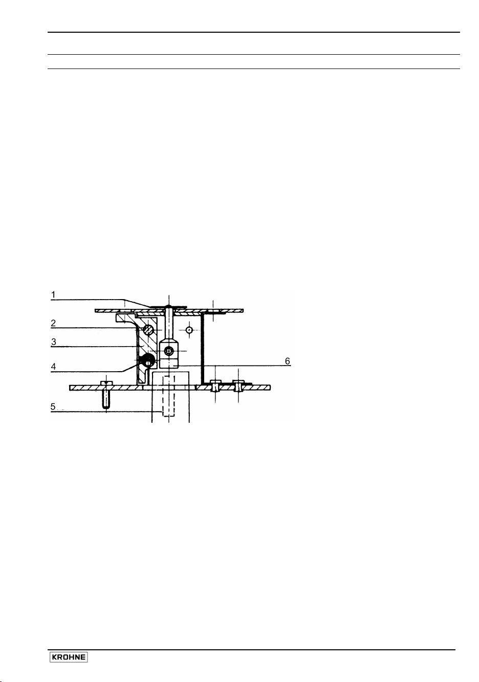
3.2.1 Type G indicator
The limit switch adjustment is indicated by a green strip (normally closed switch) or a black strip
(normally open switch) in a graduated window. For flow switches manufactured before September 1,
1991, the strips are red (normally closed switch) or orange (normally open switch).
Each graduation corresponds to 1/10 of the total measuring range, i.e. 35 l/h for a flow range of
50…400 l/h. This system enables the limit switch to be adjusted without having to circulate fluid in
the pipe. It is only necessary to adjust the micrometer screw (item 2) in order to move the switch
support (item 3) which has the coloured strip on its upper section.
“G” linear index indicator assembly
1
Index
2 Micrometer screw
3 Switch support
4 Switch
5 Control magnet
6 Following magnet
Installation and operating instructions DW 181 - 184 11
Page 12
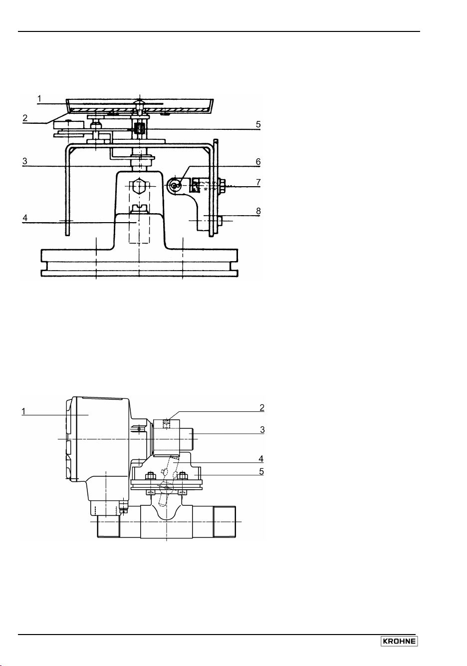
3.2.2 Type A indicator
The switch is adjusted by unlocking the adjustment screw (item 7) and repositioning the switch
support arm (item 8).
“A” graduated dial indicator assembly
1
Pointer
2 Dial
3 Following magnet
4 Control magnet
5 Mechanism
6 Switch
7 Adjustment screw
8 Switch support
3.3 Adjusting the limit switches - EEx d flow switch version
3.3.1 MS 12/BRX switch
The switch is adjusted by unscrewing the limit switch adjustment screw M8x10 (2) on top of the
pressure housing with a 4mm hexagon key. The switch (in its metal sheath) may then be
repositioned as required before retightening the screw. The original position is etched onto the
sheath.
MS 12/BRX switch assembly
1
MS 12/BRX switch
2 Limit switch adjustment
screw
3 Switch sheath
4 Switch magnet
5 Pressure housing
12 Installation and operating instructions DW 181 - 184
Page 13

4 Display
4.1 Local Flow indication
Indicator “G” Indicator “A”
All flow switches can be equipped with
indicator G. Scale marks are from 1 to 10 to
allow visual control of the flow rate. The
switching point may be changed as and when
required.
High-temperature versions are supplied without a local indicator.
The DW 181, DW 182 and DW 183 flow
switches up to meter size DN100 (4”) can be
supplied with indicator A. The dial is marked in
flow units (e.g. l/h, m³/h) to provide more
accurate flow readings. The switching points are
factory marked on the dial. With this indicator it
is also possible to adjust the switching points at
non-flowing conditions.
4.2 Limit Switches
Every flow switch can be equipped with either one or two limit switches which can be adjusted over
the entire measurement range.
Limit switch specifications
Type and number of switches Switch rating
Standard
K1(K2) single (twin for K2) bi-stable limit switch 14VA max. (max. 350 V AC, max. 0.4 A)
reed type IA42 ATF 15-45
EExi safety values Ii < 500mA, Ci = 0 nF, Li = 0 µH
With change over
K1(K2) single (twin for K2) bi-stable limit switch 3 VA max. (max. 28 V DC, max. 0.25 A)
type reed CM21…
EExi safety values Ii< 500 mA, Ci= 0 nF, Li= 0 µH
With relay
KV1 (KV2) 2000 VA max. (max. 250 V AC, max. 8 A)
Power supply: 240/110/48/24 V AC (50/60 Hz)
110/48/24 V DC
Response time: 5…12ms
EEx d values See section 4.3: EEx d version
High-temperature version (non-EEx)
single bi-stable limit switch
The switch ratings are given for standard resistance loads. Make sure you use the correct
protection circuits when using other types of load (e.g. inductive).
relay type Finder
18 VA max. (max. 220 V, max. 0.8 A)
reed type IA13….
Installation and operating instructions DW 181 - 184 13
Page 14

4.3 EEx d version
The MS 12/BRX (EEx d) switch features a flameproof aluminium enclosure. The limit switches are
type K1 and K2 bi-stable reed switches without changeovers or KV1 relays and are supplied
without a local display.
Approval EEx d IIC T6…T1
INERIS certificate 03 ATEX 0045X
Technical data
MS 12/BRX switch
Switches NC*** and NO****
Switch rating
K1, K2
(reed switch)
KV1
(relay)
Max. switching
capacity dissipated
by Ex d housing
Ambient
temperature
Process
temperature
Protection category
to EN 60529/NEMA
250
Screw connection M20 x 1.5 without
* T80…T195°C depending on the ambient
temperature and process temperature (see
section 7: Technical data).
**Maximum surface temperature of device.
***Optional: M25x1.5 or NPT ¾ threads
14 VA (350 V AC;
0,25 mA
2000 VA (250 V AC;
8 A
20 VA; 1.5 A;
380 V AC
-40…+80°C or
-40…+175°F
max. 150°C or
max. 300°F*
IP 65 / NEMA 6 when
T195…80°C or
T380…175°F*,**
cable entry fitting***
14 Installation and operating instructions DW 181 - 184
Page 15

4.4 High-temperature version (KROHNE temperature class H3, non-EEx)
All DW 18 switches can be supplied for high-temperature service up to max. 300°C or 570°F but
without indicator.
The switches are located in a PTFE cartridge fastened directly to the measuring unit.
Sealing material:
DW 181 / DW 182 Klingerit (asbestos-free)
DW 183 / DW 184 Klingerit or fully welded (optional)
Cable connection (350 mm or 13 ¾ ”) to
aluminium terminal housing: fibre glass sheathing
Technical data
MS 14 (NC*** or NO****) switch
Max. switching
capacity
Ambient temperature -25…+60°C or
Protection category
to EN 60529/IEC 529
Cable fitting PG 9 (supplied)
*** NC: switch that is “normally closed” during operation (closed switch when flow is increasing)
**** NO: switch that is “normally open” during operation (closed switch when flow is decreasing)
20 VA; 0,5 A; 250 V DC
-15…+140°F
IP 44
4.5 Tropical version (non-EEx)
The flow switch junction boxes are equipped with an Amphenol socket outlet for use in tropical
climates. The matching plug is also supplied.
1-5 Terminals
6 Connecting plug
Switch used Terminals used Connection data
K1 1,2 4 For switch K1
For ground connection
K2 1,2
3,5
4
KV1 1,2
3,4,5
Installation and operating instructions DW 181 - 184 15
For switch K1
For switch K2
For ground connection
For power supply
For change over (SPDT)
Page 16

5 Service
5.1 Maintenance
In normal operation no maintenance is required. However, the flow switch must be cleaned if
particles in suspension in the liquid build up on the measuring mechanism.
Caution
Check that the cleaning product used will not chemically react with (i.e.
corrode) the component materials.
5.2 Exploded view of instruments
DW 183 Std / EEx ia DW 184 Std / EEx ia
52a Pressure resistant housing
52b PTFE ring
52c Washer
52d Tube
52e O-ring
53 Magnet lever with measuring disc
54 Measuring spring
55 Nut
56 Spring washer
57 Tubular body with collar and flanges
58 PTFE gasket
62a Pressure resistant housing
62b PTFE ring
62c Washer
62d Tube
62e O-ring
63a Measuring disc
63b Magnet lever
64 Measuring spring
65 Nut
66 Spring washer
67 Flange with stilling well
68 PTFE gasket
The parts listed above are not supplied separately. Please refer to section 5.3: Spare parts for
a list of available spare parts.
16 Installation and operating instructions DW 181 - 184
Page 17

DW 182 (181) Std / EEx ia with indication G DW 182 (181) Std / EEx ia with indication A
DW 182 H3/K1 High-temperature version (Std)
9 Pressure resistant housing
10 O-ring
11 Magnet lever
12 Measuring spring complete
13 PTFE-ring
14 Measuring disc
15 Tubular body
17 Snap ring
18 Screw
48 Reed switch H3/K1
49 Mount
50 Nut
51 Hexagon socket head screw
The parts listed above are not supplied
separately. Please refer to section 5.3: Spare
parts for a list of available spare parts.
Installation and operating instructions DW 181 - 184 17
Page 18

5.3 Spare parts
Measuring spring DW 181 / 182 "C"
Magnet lever (Tag 11)/ PTFE Ring (Tag 13)/ Measuring spring (Tag 12)/ Measuring disc (Tag 14)
DN N° Code DN N° Code
DN15
C011 XF71010100 C041 XF71010800
DN40
C012 XF71010200 C042 XF71010900
DN 25
C013 XF71010300
C014 XF71010400 C051 XF71011100
DN50
C021 XF71010500 C052 XF71011200
C043 XF71011000
C022 XF71010600 C053 XF71011300
C023 XF71010700
C054 XF71011400
Measuring spring DW 181 / 182 "E"
Magnet lever (Tag 11)/ PTFE Ring (Tag 13)/ Measuring spring (Tag 12)/ Measuring disc (Tag 14)
DN N° Code DN N° Code
DN15
E015 XF71011500 E045 XF71012300
E016 XF71011600
E017 XF71011700 E055 XF71012500
DN40
E046 XF71012400
DN50
E018 XF71011800 E056 XF71012600
DN 25
E019 XF71011900
E025 XF71012000
E026 XF71012100
E027 XF71012200
Measuring spring DW 183 (2 springs supplied – Tag 54)
Flow Direction Meter code n°
↔ ↑ ↓
P081 XF71012700 XF71012800 XF71012900
P082 XF71013000 XF71013100 XF71013200
P083 XF71013300 XF71013400 XF71013500
P084 XF71013600 XF71013700 XF71013800
P085 XF71013900 XF71014000 XF71014100
P086 XF71014200 XF71014300 XF71014400
P087 XF71014500 XF71014600 XF71014700
P088 XF71014800 XF71014900 XF71015000
P089 XF71015100 XF71015200 XF71015300
P101 XF71015400 XF71015500 XF71015600
P102 XF71015700 XF71015800 XF71015900
P103 XF71016000 XF71016100 XF71016200
P104 XF71016300 XF71016400 XF71016400
P105 XF71016500 XF71016600
P106 XF71016700 XF71016800 XF71016900
P107 XF71017000 XF71017100 XF71017200
P108 XF71017300 XF71017400 XF71017500
P109 XF71017600 XF71017700 XF71017800
P121 XF71017900 XF71018000
P122 XF71018100 XF71018200 XF71018300
P123 XF71018400 XF71018500
P124 XF71018600 XF71018700 XF71018800
P125 XF71018900
P126 XF71019000 XF71019100
P127 XF71019200 XF71019300
P128 XF71019400 XF71019500 XF71019600
P129 XF71019700 XF71019800
18 Installation and operating instructions DW 181 - 184
Page 19

Measuring spring DW 183 (2 springs supplied - Tag 54) continued from last page …
Meter code n°
↔ ↑ ↓
P151 XF71019900 XF71020000 XF71020100
P152 XF71020200 XF71020300 XF71020400
P153 XF71020500 XF71020600 XF71020700
P154 XF71020800 XF71020900 XF71021000
P155 XF71021100
P156 XF71021200 XF71021300 XF71021400
P157 XF71021500 XF71021600 XF71021700
P158 XF71021800 XF71021900 XF71022000
P159 XF71022100 XF71022200 XF71022300
P201 XF71022400 XF71022500 XF71022600
P202 XF71022700 XF71022800 XF71022900
P203 XF71023000 XF71023100
P204 XF71023200 XF71023300 XF71023400
P205 XF71023500 XF71023600 XF71023700
P206 XF71023800 XF71023900 XF71024000
Kit gasket DW 181 / 182
Tag Description Silicon code Viton code Perbunan code
2 O-ring D 88,49 X 3,53
8 O-ring 74 X 3 X 80 XF71030100 XF71030200 XF71030300
10 O-ring D 36,17 X 2,62
13 PTFE ring
Kit gasket DW 181…4 (ring for pressure resistant housing)
for special applications using DW 181…4 HT/H3 version
Description Code Description Code
PTFE XF71030400 Klingerit XF71030500
Pressure housing DW 181 / 182
Tag Description Standard code HT version code Ex version code
9 pressure housing
18 screw A2 70 CHC,
XF71040100 XF71040200 XF71040300
M6-20 DIN 912
16 nut A2 70 HM6
17 spring washer A4 W6
Reed switch "A" DW 181 / 182 / 183
Tag Description NO** code NC* code Changeover code
33 reed switch
32a nut A2 70H,M3
31 spring washer A2 M3 plate XF71050900 XF71051000 XF71051100
32 screw A2 70 H3-10 DIN933
30 clamp plate
Reed switch "G" DW 181 / 182 / 183
Tag Description NO** code NC* code Changeover code
34 reed switch G/K1
46 spring washer D5X9 XF71051200 XF710105300 XF71051400
47 snap ring AC E005 REF A
75 55
* NC: switch that is “normally closed” during operation (closed switch when flow is increasing)
** NO: switch that is “normally open” during operation (closed switch when flow is decreasing)
Installation and operating instructions DW 181 - 184 19
Page 20

Complete plastic housing for ...
Code Description Code Description
XF71060100 DW18/AK1 green XF71062900 DW18/GKV1 24VAC
XF71060200 DW18/AK1 black XF71063000 DW18/GKV1 48VAC
XF71060300 DW18/AK1 "INV" XF71063100 DW18/GKV1 110VAC
XF71063200 DW18/GKV1 220VAC
XF71060400 DW18/AK2 green/green
XF71060500 DW18/AK2 black/black XF71063300 DW18/GKV1 24VDC
XF71060600 DW18/AK2 green/black XF71063400 DW18/GKV1 48VDC
XF71060700 DW18/AK2 black/green XF71063500 DW18/GKV1 110VDC
XF71060800 DW18/AKV1 24VAC XF71063600 DW18/GKV2 NC 24VAC
XF71060900 DW18/AKV148VAC XF71063700 DW18/GKV2 NC 48VAC
XF71061000 DW18/AKV1 110VAC XF71063800 DW18/GKV2 NC 110VAC
XF71061100 DW18/AKV1 220VAC XF71063900 DW18/GKV2 NC 220VAC
XF71061200 DW18/AKV1 24VDC
XF71061300 DW18/AKV1 48VDC XF71064000 DW18/GKV2 NC 24VDC
XF71061400 DW18/AKV1 110VDC XF71064100 DW18/GKV2 NC 48VDC
XF71064200 DW18/GKV2 NC 110VDC
XF71061500 DW18/AKV2 24VAC
XF71061600 DW18/AKV2 48VAC XF71064300 DW18/KV1/BRX NC 220V AC
XF71061700 DW18/AKV2 110VAC XF71064400 DW18/KV1/BRX NC 110V AC
XF71061800 DW18/AKV2 220VAC XF71064500 DW18/KV1/BRX NC 110V DC
XF71061900 DW18/AKV2 24VDC XF71064600 DW18/KV1/BRX NC 48V AC
XF71062000 DW18/AKV2 48VDC XF71064700 DW18/KV1/BRX NC 48V DC
XF710612100 DW18/AKV2 110VDC XF71064800 DW18/KV1/BRX NC 24V AC
XF71064900 DW18/KV1/BRX NC 24V DC
XF71062200 DW18/GK1 green
XF71062300 DW18/GK1 black XF71065000 DW18/KV1/BRX NO 220V AC
XF71062400 DW18/GK1 INV.yellow XF71065100 DW18/KV1/BRX NO 100V AC
XF71065200 DW18/KV1/BRX NO 110V DC
XF71062500 DW18/GK2 green/green XF71065300 DW18/KV1/BRX NO 48V AC
XF71062600 DW18/GK2 black/black XF71065400 DW18/KV1/BRX NO 48V DC
XF71062700 DW18/GK2 green/black XF71065500 DW18/KV1/BRX NO 24V AC
XF71062800 DW18/GK2 black/green XF71065600 DW18/KV1/BRX NO 24V DC
NC: switch that is “normally closed” during operation (closed switch when flow is increasing)
NO: switch that is “normally open” during operation (closed switch when flow is decreasing)
Kit indicator type A Kit indicator type G
Tags Description Code Tags Description Code
22…29 Indicator sub-
assembly (A)
XF71065900 36…47 Indicator sub-
assembly (A)
XF71066000
Kit cap/cover DW 181/182/183
Tag Description Code
1 cap
2 O-ring Perb D 88,49 X 3,53 XF71070100
4 locking pin 316L for cover
5+6 gasket + cover + nut
20 Installation and operating instructions DW 181 - 184
Page 21

Kit measuring system Reed switch for EXD or HT versions
Tags Description Code Tag Description Code
52a…e,
53…56,57
/ RR
DW 183
XF71080100 48
XF71080400
/ RR / HT
- DW 183
XF71080300
MS 14/HT NC XF 71051500 DW 183
MS 14/HT NC XF 7101600
- MS 12/BRX (EXD) NC XF 71051700
- MS 12/BRX (EXD) NO XF 71051800
/ RR / EXD
5.4 Inspection procedure
5.4.1 Inspection procedure: measuring assembly
Check the condition of the measuring system, cone-disc or nozzle-disc. Check the condition of the
spring. In the event of leaks between the body and the cap, tighten the four bolts securing the cap.
Change the O-ring if necessary. Carefully follow the maintenance procedures in section 5.5.
5.4.2 Inspection procedure: housing (DW181 & DW182 models)
Check switch operation using an ohmmeter. Check the operation of the indicating mechanism. By
removing the lock ring (Tag no. 7, section 5.2) holding the housing onto the assembly, it is possible
to remove the housing from the measuring body without removing the flow switch from the pipe, or
stopping the flow. Carefully follow the maintenance procedures in section 5.5.
Installation and operating instructions DW 181 - 184 21
Page 22

5.5 Basic servicing procedures
DW 181…4 servicing by the customer is limited by warranty to:
• Changing the position of the dial on the type A indicator
• Removing the display assembly
• Removing the spring-loaded probe assembly
• Changing gaskets in DW 183 flow controllers
Other repairs must be done by KROHNE-authorized service staff.
Read all servicing instructions carefully.
5.5.1 Changing the position of the dial on the type A indicator
For the “A” indication version, it may be necessary to modify the position of the dial when flow
direction has been reversed, in order to read the flow rate correctly. Follow the steps 1 to 6.
Step 1
Remove the locking pin and remove the cap.
Warning :
Do not remove the 4 bolts holding the pressure housing onto the measuring
tube.
1
Dial
2 Screwdriver
Step 2
Extract the pointer using an extractor or the flats of two screwdrivers placed at either side of the
pointer.
Step 3
Unscrew the dial.
22 Installation and operating instructions DW 181 - 184
3
Pointer
4 Screwdriver
5 Dial
Page 23

Step 4
Reposition the dial as required; attachment holes are provided to reposition the dial in 90° steps. Fit
screws.
6
Dial
7 Screwdriver
Step 5
Hold the pivoting arm and fit the pointer aligned with zero.
Step 6
Reinstall the cap and locking pin.
8 Interference fit between pointer shaft and
hole in dial
9 Pointer
10 Dial
11 Pivoting arm
5.5.2 Removing the display assembly: operating faults in the housing DW18x Std /EExia
flow controllers equipped with type G or A indicators
Warning :
Do not remove the 4 bolts holding the pressure housing onto the measuring
tube.
If the fault lies inside the housing, return the display assembly to the factory for standard
replacement. The display may be removed under flow conditions.
• Remove the whole display assembly from the pressure housing by extracting the snap-ring
underneath the display. See section 5.2 for the exploded views of the DW18 Std/EExia devices to
locate this component (Tag no. 7).
Installation and operating instructions DW 181 - 184 23
Page 24

5.5.3 Cleaning the springs or changing the measuring system sub-assembly
Warning:
Remember to shut off the flow before
performing this operation
Step 1
UNSCREW the 4 nuts and washers dia. M12 (1).
Step 2
SEPARATE the two components (2) and (3) using a
screwdriver.
Step 3
REMOVE the pressure housing (2) in the direction of
the arrow F.
Either Step 4A…
CLEAN the springs (4)
… or Step 4B
CHANGE the measuring system sub-assembly
Step 5
REASSEMBLE by following instructions 1, 2, 3 and 4 in
reverse order. Take care to orient the measuring disc
(A) so that it is facing upstream.
5.5.4 Changing gaskets in DW 183 flow controllers
Warning:
Remember to shut off the flow before
performing this operation
Step 1
UNSCREW 4 nuts and washers dia. M12 (1).
Step 2
SEPARATE the two components (2) and (3) using a
screwdriver.
Step 3
REMOVE the pressure housing (2) in the direction of
the arrow F.
Step 4
REMOVE the gaskets from their recess (4).
Step 5
CHANGE the gaskets and reassemble by following
instructions 1, 2, 3 and 4 in reverse order. Take care to
orient the measuring disc (A) so that it is facing
upstream.
24 Installation and operating instructions DW 181 - 184
Page 25

6 Technical Data
DW 181 DW 182 DW 183 DW 184
Full-scale range (100% values)
Flow rate m3/h 0.16…30 0.16…30 24…250 –
(US GPM) (0.7…132) (0.7…132) (106…1100)
Flow velocity m/s
(ft/s)
Connection
Pipe thread G
Flanges to DIN 2501 –
(NFE 29203)
Flanges to ANSI B16.5 –
Class 150 lb/RF
Information on other standards and pressure ratings supplied on request
Measuring system
Measuring disc C C – –
with tapered tube
Nozzle with baffle E E – –
Baffle – – P P
Indicator
Scale division 1 to 10 G G G G
in flow units A A
Pipe run / flow direction
Vertical/upwards VU VU VU –
Vertical/downwards VO VO VO –
Horizontal/either way H H H H
Max. operating pressure*, ***
- ≤DN50 or 2”: ≤DN150 or 6”: -
40bar or
- ≥DN65 or 3”: ≥DN200 or 8”: -
16 bar or
DN150 PN16 DN150 PN16
<13 bar (for
DN80 PN40 DN80 PN40
<25 bar (for
* Information on higher pressure levels supplied on request, ** PN 16 optional,
*** Subject to process connection used and flange temperature
Installation and operating instructions DW 181 - 184 25
– – – 0.4…4
(0.66…1.31)
3
/4” … 2”
580psig
– – –
DN15- (DN65), DN150/
DN50/PN40 DN100, DN125, PN16…PN25
(DN65/PN16) DN150/PN16
DN80/PN40,
1
DN200/PN10
/2”…2” (21/2”) 3” (21/2”)…8” 6”
40 bar or
580 psig
230 psig
A (≤DN100 / 4”)
16 bar or
230 psig
10 bar or
145 psig**
–
25 bar or
365 psig
<13 bar (for
dangerous
fluids only –
group 1
Directive
dangerous fluids
only –group 1
Directive
67/548/CEE -)
67/548/CEE -)
<25 bar (for
dangerous
fluids only –
group 1
Directive
dangerous fluids
only –group 1
Directive
67/548/CEE -)
67/548/CEE -)
Page 26

Product temperature ***
Standard
Housing with ventilation
HT–version w/o
indicator
≤120°C or
≤250°F
≤150°C or
≤300°F
≤300°C or
≤570°F
≤120°C or
≤250°F
≤150°C or
≤300°F
≤300°C or
≤570°F
≤120°C or
≤250°F
≤150°C or
≤300°F
≤300°C or
≤570°F
*** Subject to process connection used and flange temperature
≤120°C or
≤250°F
≤150°C or
≤300°F
≤300°C or
≤570°F
26 Installation and operating instructions DW 181 - 184
Page 27

Special conditions for ATEX applications
Flow indicator DW18* EEx d
Authorized markings: II 1/2 GD EEx d IIC T…* IP65 T…°C**,***
Temperature Class Process temperature Ambient temperature range
T6 / T80°C or 175°F**
T5 / T95°C or 200°F**
T4 / T130°C or 265°F**
T3 / T195°C or 380°F**
T(fluid) ≤60°C or 140°F
T(fluid) ≤80°C or 175°F
T(fluid) ≤120°C or 250°F
T(fluid) ≤150°C or 300°F
-40…+50°C or -40…+120°F
-40…+50°C or -40…+120°F
-40…+60°C or -40…+140°F
-40…+80°C or -40…+175°F
Flow indicator DW18* EEx ia
Authorized markings:
II 1 GD EEx ia IIC T…* IP65 T…°C**,***
Temperature Class Process temperature Ambient temperature range
T6 / T80°C or 175°F**
T5 / T95°C or 200°F**
T4 / T130°C or 265°F**
T3 / T195°C or 380°F**
T(fluid) ≤60°C or 140°F
T(fluid) ≤80°C or 175°F
T(fluid) ≤120°C or 250°F
T(fluid) ≤150°C or 300°F
-40…+40°C or -40…+105°F
-40…+40°C or -40…+105°F
-40…+50°C or -40…+120°F
-40…+80°C or -40…+175°F
* Maximum surface temperature of device
** T3, T4, T5 or T6 according to process temperature and ambient temperature
*** T195…80°C according to process temperature and ambient temperature
Viscosity
Standard mPa.s
lb/ft.s
Special version mPa.s
lb/ft.s
Repeatability
≤30 or
≤20x10-3
>30 or
>20x10
-3
≤30 or
≤20x10-3
>30 or
>20x10-3
≤30 or
≤20x10-3
>30 or
>20x10-3
≤30 or
≤20x10-3
>30 or
>20x10-3
±3% ±3% ±3% ±3%
(switching point)
Measuring accuracy
(Indicator A)
Protection category
±15% ±15% ±15%
(≤DN100, 4”)
IP 55 (standard version)
–
to EN 60529 / IEC 529 IP 44 (high-temperature version)
IP 65 (ATEX version)
Electromagnetic
EN 50081-1 and 50082-2
compatibility (EMC)
Limit switches
Type Number and description
K1 1 N/C* or 1 N/O* switch (bistable) or 3-wire SPDT (change over)
K2 1 N/C* or 1 N/O* switch (bistable) or 3-wire SPDT (change over)
2 N/C* or 2 N/O* switches also possible in conjunction with high-
temperature version H3
KV1, KV2 1,2 changeover switches (bistable) with amplifier relay
Type Max. switching capacity rating
K1, K2 (standard) max. 14 VA (max. 350 V AC; max. 0.4 A)
K1, K2 with changeover max. 3 VA (max. 28 V DC; max. 0.25 A)
EEx d characteristics max. dissipation (Ex d housing): 20 VA; max. 380 V AC; max. 1.5 A
EEx ia safety values Ii < 500 mA, Ci = 0 nF, Li = 0 µH
Reed switch, HT 18 VA (max. 220 V; max. 0.8 A)
KV1, KV2 max. 2000 VA (max. 250 V AC, max. 8 A)
Amplifier relay characteristics
Power supply 240/110/48/24 V AC, 110/48/24 V DC
Response time 5…12 ms
* Refer to section 2: Electrical connections for definition.
Installation and operating instructions DW 181 - 184 27
Page 28

6.1 Flow range table by flow range code
Meter size
DW 181 DW 182 Code Flow range
– Indicator G and A
Flanges for q
Screw DIN ASME l/h US GPM mbar psig mbar psig
3
/4”
15 1/2”
C 011 20…160 0.09…0.70 16 0.23 80 1.16
C 012 50…400 0.22…1.76 67 0.97 176 2.55
C 013 150…1000 0.66…4.40 140 2.03 440 6.38
C 014 300…2500 1.32…11.01 150 2.18 490 7.11
E 015* 64…160 0.28…0.70 65 0.94 370 5.37
E 016* 100…250 0.44…1.10 150 2.18 870 12.62
E 017 160…400 0.70…1.76 18 0.26 110 1.60
E 018 250…630 1.10…2.77 40 0.58 270 3.92
E 019 400…1000 1.76…4.40 18 0.26 110 1.60
1” 25 1” C 021 200…1600 0.88…7.04 18 0.26 80 1.16
C 022 300…2500 1.32…11.01 26 0.38 180 2.61
C 023 500…4000 2.20…17.61 85 1.23 400 5.80
E 025 640…1600 2.82…7.04 15 0.22 110 1.60
E 026 1000…2500 4.40…11.01 45 0.65 240 3.48
E 027 1600…4000 7.04…16.61 25 0.36 140 2.03
11/2” 40 11/2” C 041 500…4000 2.20…17.61 14 0.20 68 0.99
C 042 800…6300 3.52…27.74 32 0.46 110 1.60
C 043 1200…10000 5.28…44.03 60 0.87 160 2.32
E 045 2500…6300 11.01…27.74 15 0.22 100 1.45
E 046 4000…10000 17.61…44.03 50 0.73 260 3.77
2” 50/65 2”/21/2” C 051 1200…10000 5.28…44.03 30 0.44 80 1.16
Pressure loss p
for q
min.
max.
max
C 052 2000…16000 8.81…70.45 65 0.94 260 3.77
C 053 2500…20000 11.01…88.06 72 1.04 350 5.08
C 054 7500…30000 33.02…132.09 47 0.68 360 5.22
E 055 6400…16000 28.18…70.45 20 0.29 110 1.60
E 056 8000…16000 35.00…70.45 30 0.44 140 2.03
* only with indicator G
28 Installation and operating instructions DW 181 - 184
Page 29

Meter size
DW 183
Indicator G –
Flow range
Code Indicator A –
Flow range
Code Pressure loss
p
max.
DIN ASME m3/h US GPM m3/h US GPM mbar psig
65/ 80 21/2”/3” 10…24 44…106 P 081 - - - 10 0.15
16…40 70…176 P 082 10…40 44…176 P 086 20 0.29
20…50 88…220 P 083 13…50 55…220 P 087 10 0.15
24…60 106…264 P 084 15…60 66…264 P 088 12 0.17
28…70 123…308 P 085 17…70 75…308 P 089 12 0.17
100 4” 16…40 70…176 P 101 - - - 10 0.15
24…60 106…264 P 102 15…60 66…264 P 106 23 0.33
32…80 141…352 P 103 20…80 88…352 P 107 14 0.20
40…100 176…440 P 104 25…100 110…440 P 108 23 0.33
28…120 211…528 P 105 30…120 132…528 P 109 33 0.48
125 5” 24…60 106…264 P 121 - - - 20 0.29
40…100 176…440 P 122 25…100 110…440 P 126 24 0.35
48…120 211…528 P 123 30…120 132…528 P 127 26 0.38
60…150 264…660 P 124 37…150 163…660 P 128 24 0.35
70…180 308…793 P 125 45…180 198…793 P 129 24 0.35
150 6” 40…100 176…440 P 151 - - - 30 0.44
60…150 264…660 P 152 37…150 163…660 P 156 32 0.46
70…180 308…793 P 153 45…150 198…793 P 157 37 0.54
90…120 528…969 P 154 55…220 242…969 P 158 34 0.49
100…250 440…1101 P 155 65…250 286…1101 P 159 30 0.44
200 8” 60…150 264…660 P 201 - - - 35 0.51
70…180 308…793 P 202 - - - 40 0.64
90…220 396…969 P 203 55…220 242…969 P 205 44 0.64
100…250 440…1101 P 204 65…250 286…1101 P 206 40 0.58
Installation and operating instructions DW 181 - 184 29
Page 30

Flow table
DW 184 for measuring tube
Flow velocity Scale ratio
m/s ft/s
…0.4 0.66…1.31 1 : 2
≥DN250 (10”)
0.2
(or 65) 0.2…1 1.31…3.28 1 : 2.5
1…4 3.28…13.12 1 : 4
4 13.12 1 : 4
6.2 Instrument version materials
Version Cap Gasket * Measuring
system
DW 181/B Stainless
Steel 316 L
DW 181/RR Stainless
Steel 316 L
DW 182/RR Stainless
Steel 316 L
DW 183/N Stainless
Steel 316 L
DW 183/R Stainless
Steel 316 L
DW 183/RR Stainless
Steel 316 L
DW 184/N Stainless
Steel 316 L
DW 184/R Stainless
Steel 316 L
DW 184/RR Stainless
Steel 316 L
Buna Stainless
Steel 316 L
Buna Stainless
Steel 316 L
Buna Stainless
Steel 316 L
Buna Stainless
Steel 316 L
Buna Stainless
Steel 316 L
Buna Stainless
Steel 316 L
Buna Stainless
Steel 316 L
Buna Stainless
Steel 316 L
Buna Stainless
Steel 316 L
*Viton, silicone, or Klingerit gaskets on request. DW 184/R: steel-clad flanges used in all cases.
* *Steel flanges for >DN100 or 4” instruments have stainless steel 316 L cladding.
Measuring
Connection Housing
tube
Bronze Bronze Polycarbonate
Stainless
Steel 316 L
Stainless
Steel 316 L
Stainless
Steel 316 L
Stainless
Steel 316 L
Polycarbonate
Polycarbonate
Steel Steel Polycarbonate
Stainless
Steel * * Polycarbonate
Steel 316 L
Stainless
Steel 316 L
Stainless
Steel 316 L
Polycarbonate
Steel Steel Polycarbonate
Stainless
Steel * * Polycarbonate
Steel 316 L
Stainless
Steel 316 L
Stainless
Steel 316 L
Polycarbonate
30 Installation and operating instructions DW 181 - 184
Page 31

7 Dimensions and Weights
Type Connection Dimension h Dimension L Weight
DIN ASME mm inches mm inches kg lb
DW 181 G3/4” 115 4.53 135 5.31 1.7 3.75
Std/EEx ia G1” 120 4.72 160 6.30 1.8 3.97
G11/2" 130 5.12 180 7.09 2.2 4.85
G2” 135 5.31 190 7.48 2.6 5.73
DW 182 15
Std/EEx ia 25 1" 120 4.72 200 7.87 4.0 8.82
40 11/2" 130 5.12 200 7.87 5.5 12.13
50 2" 135 5.31 200 7.87 7.2 15.87
65 21/2" 135 5.31 200 7.87 9.3 20.50
DW 183 65 21/2” 185 7.28 200 7.87 11.5 25.35
Std/EEx ia 80 3" 185 7.28 200 7.87 12.5 27.56
100 4" 195 7.68 200 7.87 14.0 30.86
125 5" 210 8.27 300 11.81 18.0 39.68
150 6" 220 8.66 300 11.81 23.0 50.71
200 8" 250 9.84 300 11.81 35.0 77.16
DW 184
150 6" 13.5 29.76
Std/EEx ia
DW 181 Std / EEx ia
1
/2” 115 4.53 200 7.87 3.0 6.61
DW 182 Std / EEx ia
Dimensions in mm (inches)
Installation and operating instructions DW 181 - 184 31
Page 32

DW 183 Std / EEx ia DW 184 Std / EEx ia
Dimensions in mm (inches)
Type Connection Dimension h Dimension L Weight
DIN ASME mm inches mm inches kg lb
DW 181 G3/4” 140 5.51 135 5.31 2.35 5.18
EEx d G1” 145 5.71 160 6.30 2.45 5.40
G11/2" 155 6.10 180 7.09 2.85 6.28
G2” 160 6.30 190 7.48 3.25 7.16
DW 182 15
1
/2” 140 5.51 300 11.81 3.65 8.05
EEx d 25 1" 145 5.71 300 11.81 4.65 10.25
40 11/2" 155 6.10 300 11.81 6.15 13.56
50 2" 160 6.30 300 11.81 7.85 17.31
65 21/2" 160 6.30 300 11.81 9.95 21.94
DW 183 65 21/2” 210 8.27 400 15.72 12.15 26.79
EEx d 80 3" 210 8.27 400 15.72 13.15 28.99
100 4" 220 8.66 400 15.72 14.65 32.30
125 5" 232 9.13 400 15.72 18.65 41.12
150 6" 245 9.65 400 15.72 23.65 52.14
200 8" 275 10.83 400 15.72 35.65 78.59
DW 184 150 6" n/a n/a n/a n/a 14.15 31.20
EEx d
32 Installation and operating instructions DW 181 - 184
Page 33

DW 181 EEx d* DW 182 EEx d*
DW 183 EEx d* DW 184 EEx d*
Dimensions in mm (inches)
* The MS 12 / BRX (EEx d) switch is supplied without cable fitting. Only EEx d-certified
components and fittings are to be used with the MS 12/BRX switch.
Installation and operating instructions DW 181 - 184 33
Page 34

Type Connection Dimension h Dimension L Weight
DIN ASME mm inches mm inches kg lb
DW 181 G3/4” 76 2.99 135 5.31 1.10 2.42
HT (H3) G1” 81 3.19 160 6.30 1.20 2.65
G11/2" 91 3.58 180 7.09 1.60 3.53
G2” 96 3.78 190 7.48 2.00 4.40
DW 182 15
1
/2” 76 2.99 300 11.81 2.40 5.29
HT (H3) 25 1" 81 3.19 300 11.81 3.40 7.50
40 11/2" 91 3.58 300 11.81 4.90 10.80
50 2" 96 3.78 300 11.81 6.60 14.55
65 21/2" 96 3.78 300 11.81 8.70 19.18
DW 183 65 21/2” 146 5.75 400 15.72 10.90 24.03
HT (H3) 80 3" 146 5.75 400 15.72 11.90 26.24
100 4" 156 6.14 400 15.72 13.40 29.54
125 5" 168 6.61 400 15.72 17.40 38.36
150 6" 181 7.13 400 15.72 22.40 49.38
200 8" 211 8.31 400 15.72 34.40 75.84
DW 184 150 6" n/a n/a n/a n/a 12.90 28.44
HT (H3)
DW 181 HT (H3) DW 182 HT (H3)
Dimensions in mm (inches)
34 Installation and operating instructions DW 181 - 184
Page 35

DW 183 HT (H3) DW 184 HT (H3)
Dimensions in mm (inches)
Installation and operating instructions DW 181 - 184 35
Page 36

8 Measuring Principle
8.1 Measuring systems
Measuring system C:
A hinged measuring disc moves freely in the axis of a tapered tube (DW 181, DW 182 only). At
flowing conditions, the system adjusts so that the force acting on the disc is in equilibrium with the
spring force. Each flow rate thus corresponds to a particular position of the indicator and
simultaneously actuates the limit switches.
Measuring system E:
Instead of being located in a tapered tube, this system incorporates a nozzle (DW 181, DW 182
only) to increase the flow velocity. This version is particularly suitable for liquids with solids
content.
Measuring system P
(DW 183 and 184 flow switches only)
This is used for large nominal pipe diameters (DW 183, DW 184). It is similar to system E but
does not require a nozzle.
Measuring system C Measuring system E (P)
8.2 DW 183
The model DW 183 is recommended for pipe diameters from DN65…200, which can be installed in
any position in the piping. The diameter of the measuring tube depends on the flow to be measured
and the connection is adapted to that of the piping.
The maximum flow rate is 4 m/sec. The DW 183 is available in the “N” (carbon steel) “R” (stainless
steel-coated carbon steel) or “RR” (stainless steel) versions. The indicator and the switches are the
same as those used in the standard model.
For instruments without flow indication, the scale ratio between min. and max. range values is
1:2.5. A scale ratio of 1:4 is possible if required by the two limit switches. For instruments with flow
indication, the scale ratio is 1:4.
For vertical installation, the position of the installation and the flow direction should have been
indicated in the order for calibration in order to take the weight of the disc into account.
36 Installation and operating instructions DW 181 - 184
Page 37

Appendix A: Declaration of conformity: CE
Installation and operating instructions DW 181 - 184 37
Page 38

Appendix B: If you need to return a device for testing or repair to KROHNE
If installed and operated in accordance with these operating instructions, your device will rarely
present any problems.
Should you nevertheless need to return a device for checkout or repair, please pay strict attention
to the following points:
Due to statutory regulations concerning protection of the environment and the health and safety of
our personnel, KROHNE may only handle, test and repair returned flow meters that have been in
contact with liquids if it is possible to do so without risk to personnel and environment. This means
that KROHNE can only service your unit if it is accompanied by a certificate in line with the
following model confirming that the flow meter is safe to handle.
If the unit has been operated with toxic, caustic, flammable or water-endangering liquids, you are
kindly requested
• to check and make sure, if necessary by rinsing or neutralizing, that all cavities are free from
such dangerous substances.
(Directions on how you can find out whether the unit has to be opened and then flushed out or
neutralized are obtainable from KROHNE on request.)
• to enclose a certificate with the level gauge confirming that it is safe to handle and stating the
liquid used.
KROHNE regrets that it cannot service your flow meter unless accompanied by such a certificate.
Specimen certificate
Company: Address:
Department: Name:
Tel. No.:
The enclosed flow meter,
Type:
KROHNE Order No. or Series
No.:
has been operated with the following liquid:
Because this liquid is
water-endangering
toxic
caustic
flammable
we have
checked that all cavities in the unit are free from such substances
flushed out and neutralized all cavities in the unit
We confirm that there is no risk to man or environment through any residual liquid contained in this
flow meter.
Date: Signature:
Company stamp:
38 Installation and operating instructions DW 181 - 184
Page 39

Note
Installation and operating instructions DW 181 - 184 39
 Loading...