

Page 1
Supplementary instructions
Supplementary instructions
DK46 - DK800
DK46 - DK800
DK46 - DK800DK46 - DK800
Supplementary instructions Supplementary instructions
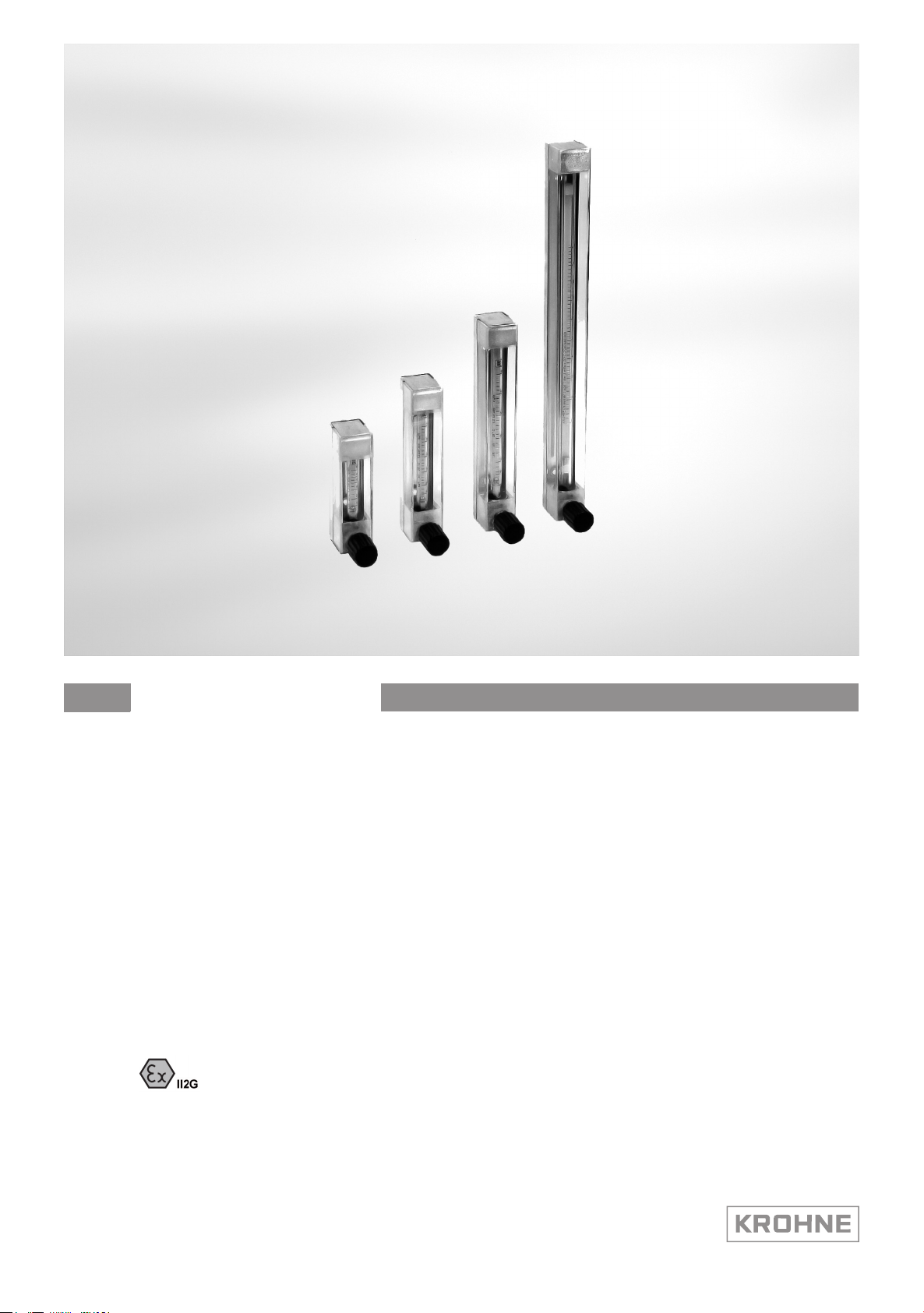
Variable area flowmeter
Device category II2G with electrical internals
Additional Ex manual
Additional Ex manual
Additional Ex manualAdditional Ex manual
© KROHNE 08/2012 - 4000430903 AD DK46/800 II2G R04 en
Page 2

CONTENTS
DK46 - DK800
1 Safety instructions 3
1.1 General ............................................................................................................................. 3
1.2 EC conformity ................................................................................................................... 3
1.3 Security information......................................................................................................... 3
2 Device description 4
2.1 Device description ............................................................................................................ 4
2.2 Description code............................................................................................................... 4
2.3 Marking............................................................................................................................. 5
2.4 Flammable products ........................................................................................................ 6
2.5 Equipment category .........................................................................................................6
2.6 Types of protection ........................................................................................................... 6
2.7 Ambient temperature / temperature classes.................................................................. 7
3 Installation 9
3.1 Installation........................................................................................................................ 9
4 Electrical connections 10
4.1 Electrical connection......................................................................................................10
4.2 Terminal assignment ..................................................................................................... 10
4.3 Connecting cable ............................................................................................................ 11
4.4 Earthing and equipotential bonding ............................................................................... 11
5 Operation 12
5.1 Start-up........................................................................................................................... 12
5.2 Operation ........................................................................................................................ 12
5.3 Static electricity.............................................................................................................. 13
6 Service 14
6.1 Maintenance ................................................................................................................... 14
6.2 Dismantling .................................................................................................................... 14
2
www.krohne.com 08/2012 - 4000430903 AD DK46/800 II2G R04 en
Page 3

DK46 - DK800
1.1 General
These supplementary Ex instructions apply for explosion-protected designs of the variable area
flowmeters DK.../../../..-Ex for the category II2G.
They supplement the installation and operating instructions for non-explosion-protected
designs.
The information in these instructions contains only the data concerning the explosion protection
of category 2.
The technical details in the installation and operating instructions for the non-explosionprotected designs apply unchanged in as far as they are not excluded or replaced by these
instructions.
1.2 EC conformity
The manufacturer declares with the EC Declaration of Conformity on his own responsibility
conformity with the protection goals of Directive 94/9/EC for use in hazardous areas with gas.
The EC Type Examination Certificate of the Physikalisch Technische Bundesanstalt (PTB) forms
the basis of the EC Declaration of Conformity:
SAFETY INSTRUCTIONS 1
If required the EC Type Test Certificate can be downloaded under www.krohne.com.
1.3 Security information
Assembly, installation, start-up and maintenance may only be performed by personnel trained in
explosion protection!
CAUTION!
The operator respectively his agent is responsible to follow further standards, directives or laws
if required due to operating conditions or place of installation. This applies particularly for the
use of easy detachable process connections such as SMS or Clamp when measuring flammable
mediums.
PTB 05 ATEX 2021 X
PTB 05 ATEX 2021 X
PTB 05 ATEX 2021 XPTB 05 ATEX 2021 X
www.krohne.com08/2012 - 4000430903 AD DK46/800 II2G R04 en
3
Page 4
2 DEVICE DESCRIPTION
2.1 Device description
Variable area flowmeters measure the volume flow of flammable and non-flammable gases and
liquids. Up to two separately adjustable electrical limit switches can be mounted to the on-site
display.
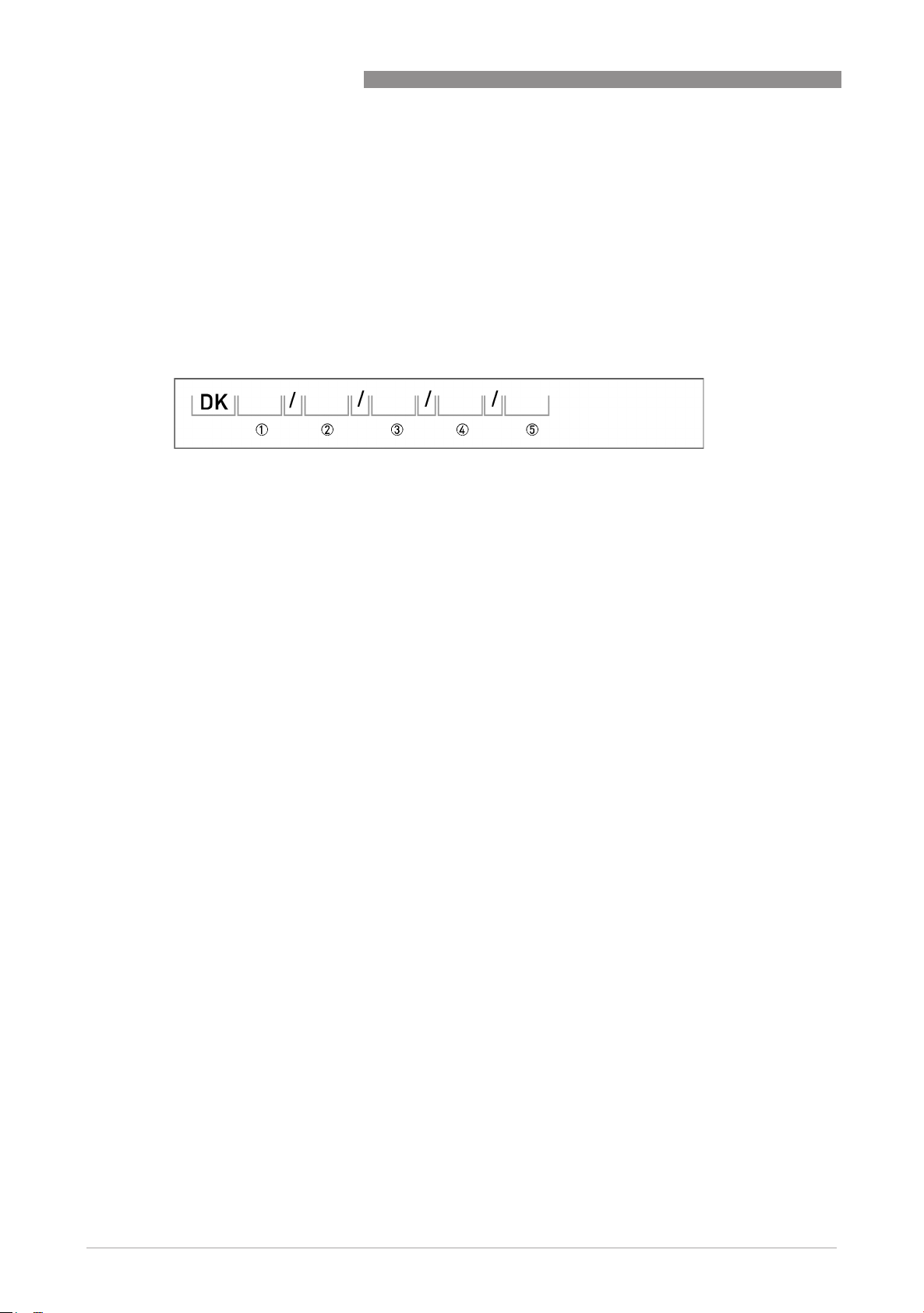
2.2 Description code
The safety description code * consists of the following elements:
1 R - with integrated inlet pressure regulator (DKR46 only)
2 Device type:
46 - Overall length of measuring cone 65 mm
47 - Overall length of measuring cone 150 mm
48 - Overall length of measuring cone 300 mm
800 - Overall length of measuring cone 100 mm
DK46 - DK800
3 Material for top and bottom fittings
N - brass
R - stainless steel
PV - PVDF
4 Differential pressure regulators
RE - inlet pressure regulator
RA - outlet pressure regulator
5 K1 - one limit switch / K2 - two limit switches
* positions which are not needed are omitted (no blank positions)
4
www.krohne.com 08/2012 - 4000430903 AD DK46/800 II2G R04 en
Page 5

DK46 - DK800
2.3 Marking
The marking for the entire device is provided on the indicator part with the marking plate shown
below.
DEVICE DESCRIPTION 2
1 Device type
2 Manufacturer
3 Notified ATEX body
4 Sizing data: temperature & pressure
5 PED data
6 Ex data
7 Electrical connection data
8 KROHNE website
9 Type of limit switch
Additional markings on the measuring device
• SN - serial number
• SO - sales order / item
• Tag-No - Measuring point identifier
• MD - manufacturing date
• PA - KROHNE order
• Vx - product configurator code
• AC - article code
www.krohne.com08/2012 - 4000430903 AD DK46/800 II2G R04 en
5
Page 6

2 DEVICE DESCRIPTION
2.4 Flammable products
Atmospheric conditions
An explosive atmosphere is defined as a mixture of air and flammable gases, vapours, mists or
dusts under atmospheric conditions with the values
T
= -20°C...+60°C / -4°F...140°F and P
atm
Outside of this range, no key data are available as to ignition behaviour for most mixtures.
Operating conditions
Variable area flowmeters operate outside of atmospheric conditions, which means that
explosion protection according to Directive 94/9/EC (ATEX) – regardless of the zone assignment
– is fundamentally not applicable due to the lack of key safety data for the interior of the
measuring unit.
CAUTION!
Operation with flammable products is only permissible if no explosive fuel/air mixture is formed
on the interior of the flowmeter under operating conditions. The user is responsible for the safe
operation of the flowmeter with regard to the temperatures and pressures of the products used.
In case of operation with flammable products the measuring units must be included in the
periodic pressure tests of the system.
= 0,8...1,1bar.
atm
DK46 - DK800
2.5 Equipment category
The flowmeters are designed in Category II 2G according to EN 60079-0 and
EN 60079-11 for use in Zone 1.
2.6 Types of protection
The circuits of the limit switches (ring sensors) are designed in Intrinsic Safety type of protection
of Category ”ia“. They can also be operated in Category ”ib“.
6
www.krohne.com 08/2012 - 4000430903 AD DK46/800 II2G R04 en
Page 7

DK46 - DK800
2.7 Ambient temperature / temperature classes
Because of the influence of the temperature of the product, no permanent temperature class is
assigned to variable area flowmeters. In fact, the temperature class of a device is a function of
the temperature of both the product and the environment. There is no distinction between
devices with one or two contacts. The classification is outlined in the following tables.
The tables take into account the following parameters:
• Ambient temperature T
• Product temperature T
• Installed equipment
• Supply type (maximum value for Pi)
INFORMATION!
The maximum permissible product temperatures listed in the tables are valid under
the following conditions:
•
The measuring device is installed and operated in accordance with the installation
instructions in the installation and operating manual.
•
It must be ensured that the flowmeter is not heated by the effects of additional heat radiation
(sunshine, neighbouring system components) and thus operated above the permissible
ambient temperature range.
•
Insulation must be limited to the piping.
Unobstructed ventilation of the indicator part must be ensured.
amb.
m
DEVICE DESCRIPTION 2
www.krohne.com08/2012 - 4000430903 AD DK46/800 II2G R04 en
7
Page 8

2 DEVICE DESCRIPTION
Temperature table in °C
DK46 - DK800
Type of limit
Maximum permissible ambient / medium temperature in °C
switch
Supply
Type 1 Type 2 Type 3
Temperature class
T6 T5 T4...T1 T6 T5 T4...T1 T6 T5 T4...T1
RC10-14.-N0...
RC15-14.-N0...
RC10-14.-N3... 70 75 75 65 75 75 50 65 75
RC15-14.-N3... 70 70 70 65 70 70 50 65 70
I7R2010-N***
I7R2015-N***
I7R2010-NL***
I7R2015-NL***
The maximum lower ambient temperature is -20°C
65 65 65 65 65 65 50 65 65
70 80 80 65 80 80 50 65 80
70 80 80 70 80 80 65 80 80
Temperature table in °F
Type of limit
switch
Maximum permissible ambient / medium temperature in °F
Supply
Type 1 Type 2 Type 3
Temperature class
T6 T5 T4...T1 T6 T5 T4...T1 T6 T5 T4...T1
RC10-14.-N0...
RC15-14.-N0...
RC10-14.-N3... 158 167 167 149 167 167 122 149 167
RC15-14.-N3... 158 158 158 149 158 158 122 149 158
I7R2010-N***
I7R2015-N***
I7R2010-NL***
I7R2015-NL***
The maximum lower ambient temperature is -4°F
149 149 149 149 149 149 122 149 149
158 176 176 149 176 176 122 149 176
158 176 176 158 176 176 149 176 176
These values may be limited by the data given in the Installation and Operating Instructions. The
maximum values given in the Installation and Operating Instructions must be taken into
consideration.
8
www.krohne.com 08/2012 - 4000430903 AD DK46/800 II2G R04 en
Page 9

DK46 - DK800
3.1 Installation
Installation and setup must be carried out according to the applicable installation installation
standards (e.g. EN 60079-14) by qualified personnel trained in explosion protection. The
information given in the Installation and Operation Instructions and the Supplementary
Installation and Operation Instructions must always be observed.
Variable area flowmeters must be installed in such a way that
• There is no danger from mechanical impact effects.
• There are no external forces affecting the indicator part.
• The device is accessible for any visual inspections that are necessary, and can be viewed from
all sides.
• The nameplate is clearly visible.
• It can be operated from a location with secure footing.
CAUTION!
The manufacturer is not liable for any damage resulting from improper use or use other than the
intended purpose. This applies in particular to hazards due to insufficient corrosion resistance
and suitability of the materials in contact with product.
INSTALLATION 3
www.krohne.com08/2012 - 4000430903 AD DK46/800 II2G R04 en
9
Page 10

4 ELECTRICAL CONNECTIONS
4.1 Electrical connection
The built-in intrinsically safe NAMUR limit switches in the variable area flowmeter DK.../../../..
may only be connected to isolation switching amplifiers with separated intrinsically safe circuits
to DIN 19234 with the following max. values:
Maximum values of the power supply units
Supply Pi [mW] Ui [V] Ii [mA]
Type 1 34 16 25
Type 2 64 16 25
Type 3 169 16 52
When connecting to intrinsically safe circuits, take into consideration the following maximum
values per circuit as a function of the limit switch (see plate on terminal box) for the energy
stores.
Type of limit switch Ci [nF] Li [µH]
RC10-14.-N0.../RC15-14.-N0... I7R2010-N***/I7R2015-N*** 210 100
RC10-14.-N3... I7R2010-NL*** 150 120
RC15-14.-N3... I7R2015-NL*** 150 70
DK46 - DK800
4.2 Terminal assignment
Connect the built-in intrinsically safe components to terminals + / - in accordance with the
following illustration and table. Connect one limit switch to each terminal block. Take note of the
polarity indicated.
Connection of limit switch - 2 wire NAMUR
1 Lower limit switch to terminal 1
2 Upper limit switch to terminal 2
The connection box includes an EMC filter unit.
For devices with just one limit switch, the connection is on terminal 1.
10
www.krohne.com 08/2012 - 4000430903 AD DK46/800 II2G R04 en
Page 11

DK46 - DK800
4.3 Connecting cable
Select the connecting cables for the intrinsically safe circuits according to the valid wiring
standard (e.g. EN 60079-14). Make sure that no residual current can form between different
intrinsically safe circuits of the variable area flowmeter. Lay cables so as to ensure that there is
sufficient distance between surfaces of the measuring unit and the connecting cable.
4.4 Earthing and equipotential bonding
If the device is not adequately grounded electrostatically by way of the process piping, make an
additional ground connection 1 by way of the ground connection. The location of the ground
connection on the back rail is shown below. This connection merely ensures electrostatic
connection of the device and does not meet the requirements for equipotential bonding.
ELECTRICAL CONNECTIONS 4
www.krohne.com08/2012 - 4000430903 AD DK46/800 II2G R04 en
11
Page 12

5 OPERATION
5.1 Start-up
Make the following checks before starting up the device:
• Suitability of the materials used for the measuring unit and for the gaskets for adequate
resistance to corrosion from the process product.
• Correct connection of the built-in electrical components.
• Visual inspection of the single-core non-sheathed cables of the ring sensors, laid inside the
indicator, for signs of damage.
5.2 Operation
The limit switches can be set during operation. To do so, first remove the protective cover. Fix
the limit switch 2 to the back rail 3 of the variable area flowmeter using the two clamping
screws 1. Close the cover immediately after the limit switches have been set.
DK46 - DK800
CAUTION!
Avoid pinching or damaging the single-core cable of the limit switches when setting the switches
and closing the cover. It should be laid in the grooves of the back rail. If the cable is damaged in
any way, the variable area flowmeter will need to be replaced!
12
www.krohne.com 08/2012 - 4000430903 AD DK46/800 II2G R04 en
Page 13

DK46 - DK800
5.3 Static electricity
Flow-induced static charge
In variable area flowmeters, it is possible under field conditions for charge separation to occur in
the measuring tube due to the transport of non-conductive fluids and/or when the flow comes
into contact with non-conductive internals.
In glass devices, it is basically possible for the electrostatic field generated inside the measuring
tube to "punch through" to the outside of the device.
For that reason, variable area flowmeters need to be permanently grounded by the operator by
way of the process connections in order to allow discharge of electrostatic build-up.
The operator is also responsible for extending the ground continuity of the process pipeline. If
grounding cannot be made via the process connections, e.g. top and bottom connection blocks
are made of plastic, the flowmeter should be connected to the local ground potential via the
connection to ground. This connection only ensures electrostatic grounding of the device and
does not meet the requirements for equipotential bonding.
OPERATION 5
When dust-free gases or liquids are measured, the flow rate should not exceed 20 times the
nominal flow rate. The max. allowable working pressure PS printed on the type nameplate is to
be noted.
www.krohne.com08/2012 - 4000430903 AD DK46/800 II2G R04 en
13
Page 14

6 SERVICE
6.1 Maintenance
The variable area flowmeter does not require any maintenance under normal operating
conditions and when used for the intended purpose. Within the scope of checks required to be
carried out in hazardous areas to maintain systems in proper working order, the following visual
inspections should be carried out at regular intervals:
• Inspection of the housing, cable entries and incoming cables for signs of damage.
• Inspection of the measuring unit for leaks and signs of damage to the glass cone.
• Include the flowmeter in the periodic pressure testing of the process piping.
Depending on application, however, the measuring function may in unfavourable cases become
impaired through soiling of the measuring cone and/or float. The measuring unit should then be
cleaned as described in the Installation and Operating Instructions for the non-hazardous-duty
versions. In this connection, refer to the notes on dismantling.
6.2 Dismantling
Electrical connection
If at all possible, dismantling should be carried out after the flowmeter has been disconnected
from supply. If not possible, observe the boundary conditions for intrinsic safety (e.g. no
grounding or connection of different intrinsically safe circuits) during dismantling.
DK46 - DK800
Process connections
CAUTION!
Pressurized pipes to be depressurized before removing the flowmeter. Avoid uncontrolled
discharge of residual fluid from the measuring unit. Where environmentally critical products are
concerned, carefully decontaminate the wetted parts of the measuring tube after dismantling.
Removal and installation are the responsibility of the operator.
Maintenance
Maintenance work of a safety-relevant nature within the meaning of explosion protection may
only be carried out by the manufacturer, his authorised representative or under the supervision
of authorised inspectors.
14
www.krohne.com 08/2012 - 4000430903 AD DK46/800 II2G R04 en
Page 15

DK46 - DK800
.
SERVICE 6
www.krohne.com08/2012 - 4000430903 AD DK46/800 II2G R04 en
15
Page 16

KROHNE product overview
• Electromagnetic flowmeters
• Variable area flowmeters
• Ultrasonic flowmeters
• Mass flowmeters
• Vortex flowmeters
• Flow controllers
• Level meters
• Temperature meters
• Pressure meters
• Analysis products
• Products and systems for the oil & gas industry
• Measuring systems for the marine industry
Head Office KROHNE Messtechnik GmbH
Ludwig-Krohne-Str. 5
47058 Duisburg (Germany)
Tel.:+49 (0)203 301 0
Fax:+49 (0)203 301 10389
info@krohne.de
The current list of all KROHNE contacts and addresses can be found at:
© KROHNE 08/2012 - 4000430903 AD DK46/800 II2G R04 en - Subject to change without notice.
www.krohne.com
 Loading...