

Page 1

DK46I - DK47I
DK46I - DK47I
DK46I - DK47IDK46I - DK47I
Variable area flowmeter
Handbook
Handbook
HandbookHandbook
Page 2

CONTENTS
1 Safety instructions......................................................................... 4
1.1 Intended use......................................................................................................... 4
1.2 Certifications........................................................................................................ 4
1.3 Safety instructions from the manufacturer......................................................... 5
1.3.1 Copyright and data protection................................................................................... 5
1.3.2 Disclaimer.................................................................................................................. 5
1.3.3 Product liability and warranty ................................................................................... 6
1.3.4 Information concerning the documentation .............................................................6
1.3.5 Display conventions................................................................................................... 7
1.4 Safety instructions for the operator .................................................................... 7
2 Instrument description.................................................................. 8
2.1 Scope of supply .................................................................................................... 8
2.2 Device versions .................................................................................................... 9
2.2.1 Versions .....................................................................................................................9
2.2.2 Versions with regulator .............................................................................................9
2.3 Nameplate.......................................................................................................... 10
2.4 Description code ................................................................................................ 11
DK46I - DK47I
3 Installation................................................................................... 12
3.1 Notes on installation.......................................................................................... 12
3.2 Storage............................................................................................................... 12
3.3 Installation requirements .................................................................................. 13
3.3.1 Installing in the pipeline ......................................................................................... 13
3.4 Start-up .............................................................................................................. 13
4 Electrical connections ................................................................. 14
4.1 Safety instructions ............................................................................................. 14
4.2 Limit switches .................................................................................................... 14
4.3 Setting the limit switch ...................................................................................... 16
4.4 Minimum clearance between two limit switches.............................................. 17
4.5 Switching performance...................................................................................... 17
4.6 Conversion of the function................................................................................. 18
5 Service......................................................................................... 19
5.1 Maintenance....................................................................................................... 19
5.2 Spare parts availability ...................................................................................... 21
5.3 Availability of services........................................................................................ 21
5.4 Returning the device to the manufacturer ........................................................ 22
5.4.1 General information ................................................................................................ 22
5.4.2 Form (for copying) to accompany a returned instrument ......................................23
5.5 Disposal.............................................................................................................. 23
6 Technical data ............................................................................. 24
6.1 Functional principle ........................................................................................... 24
2
www.krohne.com 08/2008 • 4000360001 MA DK46I-47I-R01-en
Page 3

DK46I - DK47I
7 KROHNE measuring technology - Product overview................... 36
CONTENTS
6.2 Technical data.................................................................................................... 25
6.3 Dimensions and weights.................................................................................... 27
6.4 Measuring ranges .............................................................................................. 28
6.5 Differential pressure regulators ....................................................................... 30
www.krohne.com08/2008 • 4000360001 MA DK46I-47I-R01-en
3
Page 4

1 SAFETY INSTRUCTIONS
1.1 Intended use
The variable area flowmeters are suitable for measuring gases, vapors and liquids.
These flowmeters are particularly suitable for measuring:
• Liquids
• Hydrocarbons
• Water
• Chemicals with low corrosiveness
• Industrial gases
WARNING!
The operator shall bear sole responsibility for the use of the flowmeters with regard to
suitability, intended use and corrosion resistance of the materials used to the process product.
The manufacturer shall not be liable for any damage resulting from improper use or use for
other than the intended purpose.
Do not use any abrasive or highly viscous process products.
DK46I - DK47I
1.2 Certifications
The flowmeter meets the statutory requirements of the following EC directives:
• Pressure Equipment Directive 97/23/EC
• EMC Directive 89/336/EC for instruments with electrical options
KROHNE Messtechnik GmbH & Co. KG certifies successful testing of the product by providing
the CE Declaration of Conformity.
4
www.krohne.com 08/2008 • 4000360001 MA DK46I-47I-R01-en
Page 5

DK46I - DK47I
1.3 Safety instructions from the manufacturer
1.3.1 Copyright and data protection
The contents of this document have been created with great care. Nevertheless, we provide no
guarantee that the contents are correct, complete or up-to-date.
The contents and works in this document are subject to German copyright. Contributions from
third parties are identified as such. Reproduction, processing, dissemination and any type of use
beyond what is permitted under copyright requires written authorisation from the respective
author and/or the manufacturer.
The manufacturer tries always to observe the copyrights of others, and to draw on works created
in-house or works in the public domain.
The collection of personal data (such as names, street addresses or e-mail addresses) in the
manufacturer's documents is always on a voluntary basis whenever possible. Whenever
feasible, it is always possible to make use of the offerings and services without providing any
personal data.
SAFETY INSTRUCTIONS 1
We draw your attention to the fact that data transmission over the Internet (e.g. when
communicating by e-mail) may involve gaps in security. It is not possible to protect such data
completely against access by third parties.
We hereby expressly prohibit the use of the contact data published as part of our duty to publish
an imprint for the purpose of sending us any advertising or informational materials that we have
not expressly requested.
1.3.2 Disclaimer
The manufacturer will not be liable for any damage of any kind by using its product, including,
but not limited to direct, indirect, incidental, punitive and consequential damages.
This disclaimer does not apply in case the manufacturer has acted on purpose or with gross
negligence. In the event any applicable law does not allow such limitations on implied warranties
or the exclusion of limitation of certain damages, you may, if such law applies to you, not be
subject to some or all of the above disclaimer, exclusions or limitations.
Any product purchased from the manufacturer is warranted in accordance with the relevant
product documentation and our Terms and Conditions of Sale.
The manufacturer reserves the right to alter the content of its documents, including this
disclaimer in any way, at any time, for any reason, without prior notification, and will not be liable
in any way for possible consequences of such changes.
www.krohne.com08/2008 • 4000360001 MA DK46I-47I-R01-en
5
Page 6

1 SAFETY INSTRUCTIONS
1.3.3 Product liability and warranty
The operator shall bear responsibility for the suitability of the device for the specific purpose.
The manufacturer accepts no liability for the consequences of misuse by the operator. Improper
installation and operation of the devices (systems) will cause the warranty to be void. The
respective "Standard Terms and Conditions" which form the basis for the sales contract shall
also apply.
1.3.4 Information concerning the documentation
To prevent any injury to the user or damage to the device it is essential that you read the
information in this document and observe applicable national standards, safety requirements
and accident prevention regulations.
If this document is not in your native language and if you have any problems understanding the
text, we advise you to contact your local office for assistance. The manufacturer can not accept
responsibility for any damage or injury caused by misunderstanding of the information in this
document.
DK46I - DK47I
This document is provided to help you establish operating conditions, which will permit safe and
efficient use of this device. Special considerations and precautions are also described in the
document, which appear in the form of underneath icons.
6
www.krohne.com 08/2008 • 4000360001 MA DK46I-47I-R01-en
Page 7
DK46I - DK47I
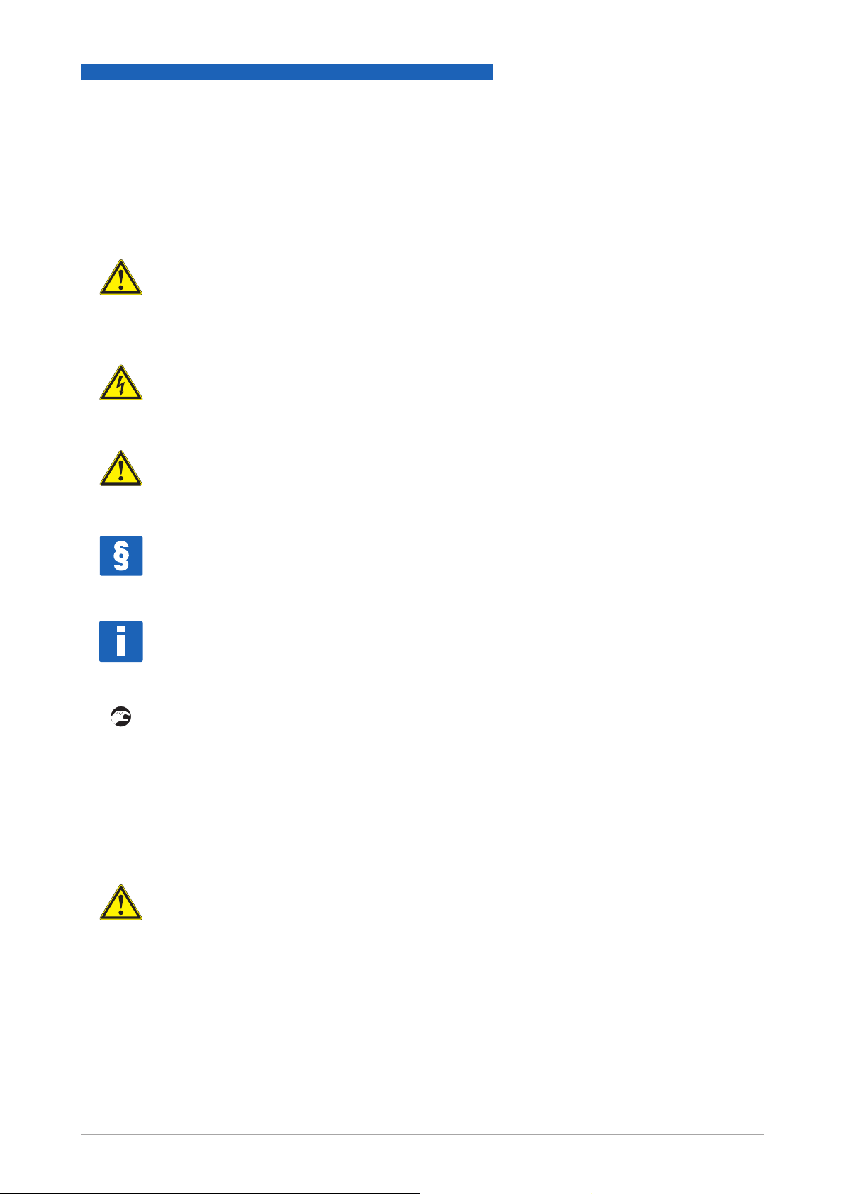
1.3.5 Display conventions
The following symbols are used to help you navigate this documentation more easily:
WARNING!
These warning signs must be observed without fail. Even only partial disregarding such
warnings can result in serious health damage, damage to the device itself or to parts of the
operator
DANGER!
This symbol designates safety advice on handling electricity.
CAUTION!
These warnings must be observed without fail. Even only partial disregarding such warnings can
lead to improper functioning of the device.
’
s plant.
SAFETY INSTRUCTIONS 1
LEGAL NOTICE!
This symbol designates information on statutory directives and standards.
NOTE!
This symbol designates important information for the handling of the device.
• HANDLING
HANDLING
HANDLINGHANDLING
This symbol designates all instructions for actions to be carried out by the operator in the
specified sequence.
i CONSEQUENCE
CONSEQUENCE
CONSEQUENCECONSEQUENCE
This symbol designates all important consequences of the previous actions.
1.4 Safety instructions for the operator
WARNING!
In general, devices from the manufacturer may only be installed, commissioned, operated and
maintained by properly trained and authorized personnel.
This document is provided to help you establish operating conditions, which will permit safe and
efficient use of this device.
www.krohne.com08/2008 • 4000360001 MA DK46I-47I-R01-en
7
Page 8

2 INSTRUMENT DESCRIPTION
2.1 Scope of supply
NOTE!
Inspect the cartons carefully for damage or signs of rough handling. Report damage to the
carrier and to your local office.
NOTE!
Check the packing list to make sure that you have received your complete order.
NOTE!
Please check on the device nameplates, that the device is supplied according to your order.
Check for the correct mains voltage printed on the nameplate. If not, contact your local
representative for advice.
DK46I - DK47I
Figure 2-1: Scope of supply
1 Flowmeter in the version ordered
2 Manual
3 Certificates, calibration certificate (supplied to order only)
8
www.krohne.com 08/2008 • 4000360001 MA DK46I-47I-R01-en
Page 9

DK46I - DK47I
2.2 Device versions
2.2.1 Versions
INSTRUMENT DESCRIPTION 2
Figure 2-2: Device versions
1 DK46I with valve and an overall length of 135 mm (5.32 inch)
2 DK47I with valve and an overall length of 245 mm (9.65 inch)
2.2.2 Versions with regulator
Figure 2-3: DK47I with differential pressure regulators
1 DK47I with inlet pressure regulator
2 DK47I with outlet pressure regulator
www.krohne.com08/2008 • 4000360001 MA DK46I-47I-R01-en
9
Page 10

2 INSTRUMENT DESCRIPTION
2.3 Nameplate
INFORMATION!
Before installing the flowmeter, make sure that the information given on the nameplate
corresponds to the ordering data.
DK46I - DK47I
Figure 2-4: Nameplates (Examples)
1 Type of meter
2 Manufacturer
3 KROHNE website
4 Design data: temperature & pressure rating
5 DGRL data
Additional markings on the flowmeter
• SN - serial number
• SO - sales order / item
• Tag-No - measuring point (customer spec.)
• MD - year of manufacture
• KO - KROHNE order
• Vx - product configurator code
• AC - article code
10
www.krohne.com 08/2008 • 4000360001 MA DK46I-47I-R01-en
Page 11

DK46I - DK47I
2.4 Description code
The description code consists of the following elements*:
1 R - With integral inlet pressure regulator (only DKR46)
2 Instrument type:
46I - Measuring cone overall length 65 mm
47I - Measuring cone overall length 150 mm
3 Material for top and bottom fittings:
R - Stainless steel
4 Differential pressure regulator:
RE - Inlet pressure regulator
RA - Outlet pressure regulator
INSTRUMENT DESCRIPTION 2
5 K1 - one limit switch
K2 - two limit switches
* positions which are not needed are omitted (no blank positions)
www.krohne.com08/2008 • 4000360001 MA DK46I-47I-R01-en
11
Page 12

3 INSTALLATION
3.1 Notes on installation
NOTE!
Inspect the cartons carefully for damage or signs of rough handling. Report damage to the
carrier and to your local office.
NOTE!
Check the packing list to make sure that you have received your complete order.
NOTE!
Please check on the device nameplates, that the device is supplied according to your order.
Check for the correct mains voltage printed on the nameplate. If not, contact your local
representative for advice.
DK46I - DK47I
3.2 Storage
• Store the flowmeter in a dry and dust-free location.
• Avoid lasting direct exposure to the sun.
• Store the flowmeter in its original packaging.
• The permissible storage temperature is from -40 to +80°C for standard meters.
12
www.krohne.com 08/2008 • 4000360001 MA DK46I-47I-R01-en
Page 13

DK46I - DK47I
3.3 Installation requirements
3.3.1 Installing in the pipeline
CAUTION!
When installing the flowmeter in the pipeline please observe the following points:
•
The variable area flowmeter has to be installed vertically (float measuring principle), flow
direction from bottom to top.
For installation recommendations please also refer to the Directive VDI/VDE 3513, Sheet 3.
•
Before installing the flowmeter, blow or flush out the pipeline leading to the flowmeter.
•
Pipelines for gas flow are to be dried before the flowmeter is installed.
•
Use connectors appropriate to the flowmeter version for the connection.
•
Align the pipes axially with the bolt holes on the flowmeter without incurring stresses.
•
If necessary, support the pipeline on both sides of the flowmeter in order to prevent vibration
from being transferred to the flowmeter.
•
Do not lay signal cables directly next to cables for the power supply.
INSTALLATION 3
3.4 Start-up
CAUTION!
When starting up the flowmeter, the following points must be observed:
•
•
•
•
•
•
•
•
•
Compare the actual operating pressure and the process temperature of the system with the
specifications on the nameplate (PS and TS); these limits must not be exceeded.
Make sure materials are compatible.
Close the needle valve at the flowmeters.
Slowly open the shut-off valve upstream and downstream of the flowmeter.
When measuring liquids, vent the pipes carefully.
When measuring gases, increase pressure slowly.
void float impact (e.g. caused by solenoid valves), as this is likely to damage the measuring
section or float.
Open needle valve at the flowmeters and set the required flow rate.
The top edge of the float marks the reading line for flow values:
Figure 3-1: Reading edge
1 Reading edge
2 Dk46I, DK47I - floatform ball
www.krohne.com08/2008 • 4000360001 MA DK46I-47I-R01-en
13
Page 14

4 ELECTRICAL CONNECTIONS
4.1 Safety instructions
DANGER!
All work on the electrical connections may only be carried out with the power disconnected. Take
note of the voltage data on the nameplate!
DANGER!
Observe national installation regulations!
WARNING!
Observe the regional occupational health and safety regulations without fail. Only work on the
device electrics if you are appropriately trained.
NOTE!
Please check on the device nameplates, that the device is supplied according to your order.
Check for the correct mains voltage printed on the nameplate. If not, contact your local
representative for advice.
DK46I - DK47I
4.2 Limit switches
The flowmeter can be equipped with a maximum of two limit switches
Type RC...-N3 and RB...-E2 with bistable function
Type RC...-N0 with monostable function
Function monostable: Switching pulse by transit of the float in the operating point, independently
of the moving direction.
Function bistable: Stable changeover by transit of the float through the operating point.
Example: Float above limit: output "High"
Float below limit: output "Low"
14
www.krohne.com 08/2008 • 4000360001 MA DK46I-47I-R01-en
Page 15

DK46I - DK47I
Electrical connection limit switches - 2-wire terminal box
1 lower limit switch - to terminal 1
2 upper limit switch - to terminal 2
The junction box includes an EMC filter unit.
ELECTRICAL CONNECTIONS 4
Electrical connection limit switches - 2-wire without terminal box
1 Limit switch (without terminal box)
2 Colour coding blue -
3 Colour coding brown +
4 external EMC filter
5 Receiver device
EMC filter unit and back rail of the flowmeter must be galvanically connected and grounded.
Electrical connection limit switch - 3-wire (RB...-E2)
• bn - brown: supply voltage +
• bk - black - switch
• bu - blue: supply voltage -
www.krohne.com08/2008 • 4000360001 MA DK46I-47I-R01-en
15
Page 16

4 ELECTRICAL CONNECTIONS
4.3 Setting the limit switch
Following procedure is to perform (DK../../K):
• Detach clamping screws 1
• Slide the limit switches over the measuring glass.
• Use the two clamping screws 1 to fasten the limit switch 3 to the back rail 1 of the
measuring device.
• Reinstall the protection cover after installation.
DK46I - DK47I
To install, first remove the measuring glass as described under chapter Maintenance.
CAUTION!
When setting the ring sensor, make sure the cable is laid such that it cannot be damaged!
Avoid CANT - glass breakage!
The connecting lead for the limit switch is routed the hole in the device bottom fitting and sealed.
For bistable limit switches with external EMC filter in separate DIN-rail housing, observe the
following:
EMC filter unit and back rail of the flowmeter must be galvanically connected and grounded.
An isolation switching amplifier with intrinsically safe control circuits NAMUR is necessary for
operation of the NAMUR limit switches.
16
www.krohne.com 08/2008 • 4000360001 MA DK46I-47I-R01-en
Page 17

DK46I - DK47I
ELECTRICAL CONNECTIONS 4
4.4 Minimum clearance between two limit switches
Where two sensors are in one device, and also where DK glass devices with limit switches are
arranged close together, minimum clearances must be maintained in order to avoid mutual
influence of the switches.
Min. clearance RC… 2-wire RB… 3-wire
1 16 mm (0.63") 45 mm (1.773")
2 6 mm (0.236") 30 mm (1.182")
4.5 Switching performance
Limit switch RC...-N0
Ball outside sensor: Signal ≥3 mA
Ball inside sensor: Signal ≤1 mA
Limit switch RC...-N3
Independent of ball position see image 1 : Signal ≥3 mA
Pre condition: The ball is located outside the sensor.
NOTE!
To get a correct mode of operation after power on the limit switches RC...-N3
through for one time 1 and 2.
Limit switch RB...-E2
Independent of ball position like transit 2: Signal ≤1 V
Pre condition: The ball is located outside the sensor.
RC...-N0
RC...-N0RC...-N0
RC...-N3
RC...-N3RC...-N3
RB...-E2
RB...-E2RB...-E2
RC...-N3 have to pass
RC...-N3RC...-N3
www.krohne.com08/2008 • 4000360001 MA DK46I-47I-R01-en
17
Page 18

4 ELECTRICAL CONNECTIONS
4.6 Conversion of the function
The bistable limit switch RC 10...N3 can be changed from NO to NC function.
The precut cable with connectors must be sufficiently long for this!
When setting the limit switch, make sure the cable is laid such that it cannot be damaged!
• Detach clamping screws 1
• Detach tensioning screw 2. Turn anti-clockwise.
• Carefully pull out the measuring glass together with the limit switch.
• Turn the limit switch 180°.
• Assemble in reverse order.
• Turn tensioning screw 2 hand-screwed
• Use a 3mm pin to tighten the lock nut with 4x ... max. 5x
DK46I - DK47I
4x ... max. 5x, 120° turns 3 clockwise.
4x ... max. 5x4x ... max. 5x
18
CAUTION!
To avoid glass breakage, the measuring glass must be
inserted concentrically between the gaskets.
Before restarting the flowmeter, check leak-tightness by suitable means.
www.krohne.com 08/2008 • 4000360001 MA DK46I-47I-R01-en
Page 19

DK46I - DK47I
5.1 Maintenance
Within the scope of routine maintenance of the system and pipelines, the flowmeter should also
be inspected for signs of fouling, corrosion, mechanical wear and leaks, as well as damage to
the measuring tube and indicator.
We advise that inspections be carried out at least once a year.
The device must be removed from the piping before cleaning.
CAUTION!
Pressurized pipes must be depressurized before removing the device.
In the case of flowmeters used for measuring aggressive or hazardous products, appropriate
safety precautions must be taken with regard to residual liquids in the measuring section.
Always use new gaskets when reinstalling the flowmeter in the pipeline.
SERVICE 5
CAUTION!
Under certain circumstances the valve packing gland may have to be adjusted during its service
life. This means that the union nut has to be retightened. If necessary, press the retaining pin
against its internal spring.
Apply a tightening torque of not more than 5 Nm.
CAUTION!
Valves that have not been actuated for a longer period of time may exhibit a higher initial
actuation torque.
www.krohne.com08/2008 • 4000360001 MA DK46I-47I-R01-en
19
Page 20

5 SERVICE
Changing the measuring cone
• Close valve upstream and downstream of the device.
• Close needle valve.
• Push protective cover upwards and remove to front.
• Turn the lock nut in the device base 1 anti-clockwise.
Devices with a top and bottom fitting made of PVDF (DK.../PV) have a tensioning screw in the
device head(Allen key 6mm).
This can be unlocked with approx. 1 full turn.
The measuring glass can be removed to the front.
DK46I - DK47I
Figure 5-1: Mainenance
CAUTION!
Residual liquid or gas may leak out!
• Install in the reverse order:
• Fix the measuring glass in position by tightening the lock
nut finger-tight in the device base 1 first of all.
• Use a 3mm pin to tighten the lock nut with 4x ... max. 5x
4x ... max. 5x 120° turns clockwise. 2
4x ... max. 5x4x ... max. 5x
CAUTION!
To avoid glass breakage, the measuring glass must be
inserted concentrically between the gaskets.
Before restarting the flowmeter, check leak-tightness by
suitable means.
20
www.krohne.com 08/2008 • 4000360001 MA DK46I-47I-R01-en
Page 21

DK46I - DK47I
5.2 Spare parts availability
The manufacturer adheres to the basic principle that operational spare parts for each device or
each important accessory part will be kept available for a period of 10 (ten) years after delivery of
the last production run for that device.
Operational spare parts are defined as parts that are subject to faults in normal operation.
5.3 Availability of services
The manufacturer offers a range of services to support the customer after expiration of the
warranty. These include repair, technical support and training.
NOTE!
For more precise information, please contact your local representative.
SERVICE 5
www.krohne.com08/2008 • 4000360001 MA DK46I-47I-R01-en
21
Page 22

5 SERVICE
5.4 Returning the device to the manufacturer
5.4.1 General information
This device has been carefully manufactured and tested. If installed and operated in accordance
with these operating instructions, it will rarely present any problems.
CAUTION!
Should you nevertheless need to return a device for inspection or repair, please pay strict
attention to the following points:
•
Due to statutory regulations on environmental protection and safeguarding the health and
safety of our personnel, manufacturer may only handle, test and repair returned devices that
have been in contact with products without risk to personnel and environment.
•
This means that the manufacturer can only service this device if it is accompanied by the
following certificate (see next section) confirming that the device is safe to handle.
DK46I - DK47I
CAUTION!
If the device has been operated with toxic, caustic, flammable or water-endangering products,
you are kindly requested:
•
to check and ensure, if necessary by rinsing or neutralizing, that all cavities are free from
such dangerous substances,
•
to enclose a certificate with the device confirming that is safe to handle and stating the
product used.
22
www.krohne.com 08/2008 • 4000360001 MA DK46I-47I-R01-en
Page 23

DK46I - DK47I
5.4.2 Form (for copying) to accompany a returned instrument
Company: Address:
Department: Name:
Tel. no.: Fax no.:
Manufacturer's order no. or serial no.:
The device has been operated with the following medium:
SERVICE 5
This medium is: water-hazardous
toxic
caustic
flammable
We checked that all cavities in the device are free from such
substances.
We have flushed out and neutralized all cavities in the
device.
We hereby confirm that there is no risk to persons or the environment through any residual media
contained in the device when it is returned.
Date: Signature:
Stamp:
5.5 Disposal
CAUTION!
Disposal must be carried out in accordance with legislation applicable in your country.
www.krohne.com08/2008 • 4000360001 MA DK46I-47I-R01-en
23
Page 24

6 TECHNICAL DATA
6.1 Functional principle
The flowmeter operates on the float measuring principle.
The measuring section consists of a glass cone in which a float can move freely up and down.
The medium flows through the flowmeter from bottom to top.
The float adjusts itself so that the buoyancy force A acting on it, the form drag W and its weight G
are in equilibrium.
DK46I - DK47I
G = A + W
Figure 6-1: Operating principle
The flow-dependent height of the float can take reading on a scale of the measuring glass.
The top edge of the float marks the reading line for flow values.
24
www.krohne.com 08/2008 • 4000360001 MA DK46I-47I-R01-en
Page 25

DK46I - DK47I
6.2 Technical data
Application range Flow measurement of liquids and gases
Measuring accuracy Directive VDI / VDE 3513, sheet 2
DK46 I Class 4
DK47 I Class 2.5
Operating pressure PS Pressure equipment directive 97/23/EC
Test pressure PT Pressure equipment directive 97/23/EC
Max. perm. operating gauge press. PS at TS =
212°F (100°C)
DK…/R (head piece and foot piece made from
stainless steel)
DK…/N (head piece and foot piece made from
brass)
1 higher pressures upon request
TECHNICAL DATA 6
145 psig (10 bar) 1
145 psig (10 bar) 1
Materials
Head piece, foot piece CrNi steel 1.4404 / 316 L, nickle-plated brass
Head piece, foot piece optional Hastelloy
Measuring tube Borosilicate glass
Float (sphere) CrNi steel 1.4401 / 316
Float options Glass, POM, titanium, Hastelloy C4
DK48 float (All) CrNi steel 1.4571 / 316 titanium, aluminum, PEEK, glass
Metering unit CrNi steel 1.4571 / 316 Ti
Valve spindle CrNi steel 1.4404 / 316 L
Standard seals PTFE / FPM
Seals options PTFE / FFKM, PTFE / EPDM
Seals options EPDM, FFKM
Protective cover Polycarbonate
Temperatures
Temperatures
TemperaturesTemperatures
Max. temperature of medium Tm +212°F (+100°C)
Max. Tm with limit switches +149°F (+65°C)
Min. temperature of medium Tm +23°F (-5°C) 1
Max. ambient temperature Tamb. +212°F (+100°C)
Max. Tamb. with limit switches +149°F (+65°C)
Min. ambient temperature Tamb. -4°F (-20°C) 1
1 other temperatures upon request
www.krohne.com08/2008 • 4000360001 MA DK46I-47I-R01-en
25
Page 26

6 TECHNICAL DATA
Technical data limit switches
Technical data limit switches
Technical data limit switchesTechnical data limit switches
Clamp-type terminal Connection box M16 x 1.5 - Cable diameter 5...10 mm
Limit switches RC10-14-N3 RC15-14-N3 RC10-14-N0 RC15-14-N0 RB15-14-E2
Switching function Bistable Bistable Monostable Monostable Bistable, 3-
Connection technology NAMUR, two-
Rated voltage U0 8 VDC 8 VDC 8 VDC 8 VDC
Current consumption 1 mA passage ↓ 3 mA - sphere beyond
Current consumption 3 mA passage ↓ 1 mA - sphere is in limit
Operating voltage Ub 10…30 VDC
Operating current Ib 0…100mA
No-load current 20mA
Output Ua - passage ↓ ≤ 1 VDC
Output Ua - passage ↑ ≥ Ub – 3 VDC
wire
NAMUR, twowire
NAMUR, twowire
monitor
NAMUR, twowire
DK46I - DK47I
wire
Three-wire
Application range of limit switches
Application range of limit switches
Application range of limit switchesApplication range of limit switches
DK46 I, DK47 I
Sphere Limit switches
Ø 4mm RC10
Ø 6 mm RC15 / RB15
Ø 8 mm -
The limit switches RC15 and RB15 (as max. contact) can only be used for up to 60 l/h (16 gal/h)
water (external diameter of the measuring glass).
26
www.krohne.com 08/2008 • 4000360001 MA DK46I-47I-R01-en
Page 27

DK46I - DK47I
6.3 Dimensions and weights
Dimensions
Dimensions
DimensionsDimensions
TECHNICAL DATA 6
[inch]
[mm]
DK46 I 5.32
DK47 I 9.65
Weights
Weights
WeightsWeights
Device DK46 I DK47 I
Weight [kg] 0.5 0.7
Weight with regulator 2.1 2.3
Process connection
Process connection
Process connectionProcess connection
a
135
245
b
± 0.01
± 0.25
4.49
8.82
114
224
c d e f
0.17
4.3
0.17
4.3
1.77
45
5.12
130
1.30
33
1.30
33
approx.
3.23
3.23
82
82
g
1.1
28
1.1
28
Standard 1/4" NPT internal thread
Options G 1/4, Ermeto 6 or 8, tube connection 6 mm or 8
mm, Dilo, Gyrolok, Swagelok
1 other connections upon request
www.krohne.com08/2008 • 4000360001 MA DK46I-47I-R01-en
1
27
Page 28

6 TECHNICAL DATA
6.4 Measuring ranges
Measuring span 10 : 1
Flow values 100%
DK46I - DK47I
Water Air
Sphere Ø
mm
4 0.65 2.5 - - 0.22 5 - 4 - - - - 0.3 8 - 4 - - - - 0.6 16 0.6 16
4 - - - - 1.5 40 1.5 40
4 - - - - 2.5 60 3.8 100
6 1.3 5 1.3 5 3.8 100 - 6 3 12 3 12 9 250 9 250
6 6.5 25 6.5 25 18 500 18 500
6 11 40 11 40 30 800 30 800
6 16 60 16 60 45 1200 - 6 25 100 25 100 - - - 8 30 120 - - - - - 8 42 160 - - - - - -
DK46 I DK47 I DK46 I DK47 I
[GPH] [l/h] [GPH] [l/h] [SCFH] [l/h] [SCFH] [l/h]
Reference condition:
water 68°F (20°C)
air 68°F (20°C), 17.4 psi (1.2 bar abs.) in a standard state
28
Other flow rate measuring ranges can be provided upon request.
The conversion of other materials or operating data (pressure, temperature, density, viscosity) is
done with the help of the calculation procedure as detailed in Directive VDI /VDE 3513
www.krohne.com 08/2008 • 4000360001 MA DK46I-47I-R01-en
Page 29

DK46I - DK47I
Valves
Valve characteristics
TECHNICAL DATA 6
Max flowrate
Water [l/h] Air [l/h]
Spindle Ø
[mm]
1 1.32 5 3.5 100 0.021 0.018
2.5 13.2 50 35 1000 0.17 0.15
4.5 42.3 160 177 5000 0.56 0.48
[GPH] [l/h] [SCFH] [l/h] [gal/min] [m3/h]
spindle Ø 1.0mm spindle Ø 2.5mm
CV/Kv valve characteristic
value
spindle Ø 4.5mm
1 Flow, air
2 Flow, water
3 Spindle rotation n
www.krohne.com08/2008 • 4000360001 MA DK46I-47I-R01-en
29
Page 30

6 TECHNICAL DATA
6.5 Differential pressure regulators
Differential pressure regulators are used to provide constant flow rates in the case of variable
inlet or outlet pressures. Minimum pressure levels are necessary to operate the regulators (see
regulator characteristics).
Differential pressure regulators are not pressure reducing valves.
Differential pressure regulators are not pressure reducing valves.
Differential pressure regulators are not pressure reducing valves.Differential pressure regulators are not pressure reducing valves.
1 Inlet pressure regulators, type RE, NRE
Inlet pressure regulators, type RE, NRE
Inlet pressure regulators, type RE, NRE Inlet pressure regulators, type RE, NRE
The regulators keep the flow rate constant in the case of a variable inlet pressure and a constant
outlet pressure.
DK46I - DK47I
Example - inlet pressure
regulator RE1000:
Current flow rate:
Outlet pressure p2 constant: 14.7 psi (1.013 bar abs.)
3
/h (1000 l/h) air
35 ft
The flow rate is constant in the device in the case of a fluctuating inlet pressure greater than 7.3
psig (0.5 bar).
2 Outlet pressure regulator, type RA, NRA
Outlet pressure regulator, type RA, NRA
Outlet pressure regulator, type RA, NRA Outlet pressure regulator, type RA, NRA
The regulators keep the flow rate constant in the case of a constant inlet pressure and a variable
outlet pressure. There must be a pressure differential between the inlet and the outlet pressure
for the outlet pressure regulator to function. The inlet pressure p1 must always be greater than
the outlet pressure p2.
Example - outlet pressure
regulator NRA 800
Current flow rate:
Inlet pressure constant: 87 psig (6 bar)
28.3 ft
3
/h (800 l/h) air
The flow rate is constant in the device in the case of a fluctuating outlet pressure of 0 ... 80 psig
(5.5 bar).
Regulator characteristics
Regulator characteristics
Regulator characteristicsRegulator characteristics
30
1 Inlet pressure regulators, type RE and
NRE
www.krohne.com 08/2008 • 4000360001 MA DK46I-47I-R01-en
2 Outlet pressure regulators, type RA and
NRA
Page 31

DK46I - DK47I
Control ranges
Control ranges
Control rangesControl ranges
TECHNICAL DATA 6
Inlet pressure regulator
Max flow rate
Water Air Min. inlet pressure Up1
[gal/h] [l/h] [ft3/h] [l/h] [psig] [bar]
RE-1000 ...10 ...40 ...35 ...1000 7.3 0.5
RE-4000 ...21 ...80 ...70 ...2000 14.5 1
...26 ...100 ...106 …3000 21.8 1.5
...42 ...160 ...141 ...4000 29 2
NRE-100 ...0.66 ...2.5 ...3.5 ...100 1.5 0.1
NRE-800 ...8.8 ...250 1.5 0.1
...28 ...800 2.9 0.2
...6.6 ...25 5.8 0.4
Outlet pressure regulator
Max flow rate
Water Air Min. pressure diff.
[gal/h] [l/h] [ft3/h] [l/h] [psig] [bar]
RA-1000 ...10 ...40 ...35 ...1000 7.3 0.5
RA-4000 ...26 ...100 ...70 …2000 14.5 1
...106 ...3000 21.8 1.5
...42 ...160 ...141 ...4000 29 2
NRA-800 ...0.26 ...1 ...8.8 ...250 1.5 0.1
...18 ...500 2.9 0.2
...6.6 ...25 ...28 ...800 5.8 0.4
www.krohne.com08/2008 • 4000360001 MA DK46I-47I-R01-en
31
Page 32

6 TECHNICAL DATA
Technical data, differential pressure regulator
Technical data, differential pressure regulator
Technical data, differential pressure regulatorTechnical data, differential pressure regulator
Standard connection 1/4" NPT
Option Serto, Ermeto 6 or 8, tube nozzle 6 mm or 8 mm,
Max. operating gauge pressure PS 145 psig (10 bar) 2
Material CrNi-Steel 1.4404
Temperature TS = 212°F (100 °C)
1 other connections upon request
2 higher pressures upon request
3 higher temperatures upon request
Dimensions with the differential pressure regulator
Dimensions with the differential pressure regulator
Dimensions with the differential pressure regulatorDimensions with the differential pressure regulator
DK46I - DK47I
Dilo, Gyrolok, Swagelok, G 1/4 1
3
Dimensions
[inch]
[mm]
DK46 I 8.27
DK47 I 8.27
a
approx.
210
210
b c
approx.
7.37
187
11.11
282
0.51
13
0.51
13
d e f
approx.
2.76
70
2.76
70
0.75
19
0.75
19
1.54
39
1.54
39
DK with inlet pressure regulator DK with outlet pressure regulator
g
3.55
90
3.55
90
32
www.krohne.com 08/2008 • 4000360001 MA DK46I-47I-R01-en
Page 33

DK46I - DK47I
.
TECHNICAL DATA 6
www.krohne.com08/2008 • 4000360001 MA DK46I-47I-R01-en
33
Page 34

6 TECHNICAL DATA
.
DK46I - DK47I
34
www.krohne.com 08/2008 • 4000360001 MA DK46I-47I-R01-en
Page 35

DK46I - DK47I
.
TECHNICAL DATA 6
www.krohne.com08/2008 • 4000360001 MA DK46I-47I-R01-en
35
Page 36

DK46I - DK47I nnnnnnnnnnnnnnnnnnnnnnnnnnnnnnnnnnnnnnnnnnnnnnnnnnnnnnnn
nn
KROHNE measuring technology - Product overview
• Electromagnetic flowmeters • Level measuring instruments
• Variable area flowmeters • Temperature measuring instruments
• Mass flowmeters • Pressure measuring instruments
• Ultrasonic flowmeters • Analysis
• Vortex flowmeters • Oil and gas industry
• Flow controllers
Addresses:
Great Britain
Germany
Northern sales office
KROHNE Messtechnik GmbH & Co. KG
Bremer Str. 133
D-21073 Hamburg
Phone:+49 (0)40 767 3340
Fax:+49 (0)40 767 33412
nord@krohne.com
ZIP code: 10000 - 29999, 49000 - 49999
Western and middle sales office
KROHNE Messtechnik GmbH & Co. KG
Ludwig-Krohne-Straße
D-47058 Duisburg
Phone:+49 (0)203 301 4416
Fax:+49 (0)203 301 10416
west@krohne.com
ZIP code: 30000 - 34999, 37000 48000, 50000 - 53999, 57000 - 59999,
98000 - 99999
Southern sales office
KROHNE Messtechnik GmbH & Co. KG
Landsberger Str. 392
D-81241 Munich
Phone:+49 (0)89 121 5620
Fax:+49 (0)89 129 6190
sued@krohne.com
ZIP code: 0 - 9999, 80000 - 89999,
90000 - 97999
Southwestern sales office
KROHNE Messtechnik GmbH & Co. KG
Rüdesheimer Str. 40
D-65239 Hochheim/Main
Phone: +49(0)6146) 827 30
Fax:+49 (0)6146 827 312
rhein-main@krohne.com
ZIP code: 35000 - 36999, 54000 56999, 60000 - 79999
Instrumentation and control
equipment catalog
TABLAR Messtechnik GmbH
Ludwig-Krohne-Str. 5
D-47058 Duisburg
Phone:+49 (0)2 03 305 88 0
Fax:+49 (0)2 03 305 8888
kontakt@tablar.de; www.tab lar.de
KROHNE sales
companies
International
Australia
Australia
AustraliaAustralia
KROHNE Australia Pty Ltd
Quantum Business Park 10/287
Victoria Rd Rydalmere NSW 2116
Phone: +61 2 8846 1700
Fax: +61 2 8846 1755
krohne@krohne.com.au
Austria
Austria
AustriaAustria
KROHNE Gesellschaft m.b.H.
Modecenterstraße 14
A-1030 Vienna
Phone:+43 (0)1/203 45 32
Fax:+43 (0)1/203 45 32 99
info@krohne.at
Belgium
Belgium
Belgium Belgium
KROHNE Belgium N.V.
Brusselstraat 320
B-1702 Groot Bijgaarden
Phone:+32 (0)2 4 66 00 10
Fax:+32 (0)2 4 66 08 00
krohne@krohne.be
Brazil
Brazil
Brazil Brazil
KROHNE Conaut Controles
Automaticos Ltda.
Estrada Das Águas Espraiadas, 230
C.P. 56 06835 - 080 EMBU - SP
Phone:+55 (0)11-4785-2700
Fax:+55 (0)11 4785-2768
conaut@conaut.com.br
China
China
ChinaChina
KROHNE Measurement Instruments
(Shanghai) Co. Ltd., (KMIC)
9th Floor, Puyuan Science Park,
Building A
396 Guilin Road
Shanghai 200233
Tel.: +86 (021) 6470 5656
Fax: +86 (021) 6451 6408
info@krohne-asia.com
Czech Republic
Czech Republic
Czech RepublicCzech Republic
Krohne CZ, spol. s r.o.
Sobìsická 156
63800 Brno
Phone: +420 (0)545.242 627
Fax: +420 (0)545 220 093
brno@krohne.cz
France
France
FranceFrance
KROHNE S.A.S.
Les Ors BP 98
F-26103 ROMANS Cedex
Phone:+33 (0)4 75 05 44 00
Fax:+33 (0)4 75 05 00 48
info@krohne.fr
Great Britain
Great BritainGreat Britain
KROHNE Ltd.
Rutherford Drive
Park Farm Industrial Estate
Wellingborough
Northants NN8 6AE
Phone:+44 (0)19 33 408 500
Fax:+44 (0)19 33 408 501
info@krohne.co.uk
CIS
CIS
CISCIS
Kanex KROHNE Engineering AG
Business Centre "POLLARS", office
164
Derbenevskaya nab., 11-B
113114 Moscow/Russia
Tel. / Fax: +7 (0)495 913-68-41
Tel. / Fax: +7 (0)495 913-68-42
Tel. / Fax: +7 (0)495 913-68-43
Tel. / Fax: +7 (0)495 913-68-44
krohne@krohne.ru
India
India
IndiaIndia
Krohne Marshall Ltd.
A-34/35, M.I.D.C. Industrial Area,
H-Block
Pimpri Poona 411018
Phone:+91 (0)202 744 2020
Fax:+91 (0)202 744 2020
pcu@vsnl.net
Iran
Iran
IranIran
KROHNE Liaison Office
North Sohrevardi Ave. 26,
Sarmad St., Apt. #9
Tehran 15539
Phone: +9821 8874 5973
Fax: +9821 8850 1268
krohne@krohneiran.com
Italy
Italy
ItalyItaly
KROHNE Italia Srl.
Via V. Monti 75
I-20145 Milan
Phone:+39 02 4300 661
Fax:+39 02 4300 6666
info@krohne.it
Korea
Korea
KoreaKorea
KROHNE Korea
Room 508 Miwon Bldg 43
Yoido-Dong Youngd eungpo-Ku
Seoul, Korea
Phone: 00-82-2-782-1900
Fax: 00-82-2-780-1749
mail@krohne.co.kr
Netherlands
Netherlands
NetherlandsNetherlands
KROHNE Nederland B.V.
Kerkeplaat 14
NL-3313 LC Dordrecht
Phone:+31 (0)78 630 6200
Fax:+31 (0)78 630 6405
Service Direct: +31 (0)78 630 6222
info@krohne.nl
Norway
Norway
NorwayNorway
KROHNE Norway A.S.
Ekholtveien 114
NO-1521 Moss
Phone:+47 (0)69 264 860
Fax:+47 (0)69 267 333
postmaster@krohne.no
Poland
Poland
PolandPoland
KROHNE Polska Sp.z.o.o.
ul. Stary Rynek Oliwski 8a
80-324 Gdansk
Phone: +48 (0)58 520 9211
Fax.:+48 (0)58 520 9212
info@krohne.pl
Switzerland
Switzerland
SwitzerlandSwitzerland
KROHNE AG
Uferstr. 90
CH-4019 Basel
Phone:+41 (0)61 638 30 30
Fax:+41 (0)61 638 30 40
info@krohne.ch
Singapore
Singapore
SingaporeSingapore
Tokyo Keiso - KROHNE (Singapore)
Pte. Ltd.
14, International Bus iness Park,
Jurong East
Chiyoda Building, #01-01/02
Singapore 609922
Phone: (65) 6567 4548
Fax : (65) 6567 9874
tks@tokyokeiso-krohne.com.sg
Republic of South Africa
Republic of South Africa
Republic of South AfricaRepublic of South Africa
KROHNE Pty. Ltd.
Bushbock Close
Corporate Park South
Midrand, Gauteng
P.O. Box 2069
Midrand, 1685
Tel.: +27 (0)11 314 1391
Fax: +27 (0)11 314 1681
midrand@krohne.co.za
Spain
Spain
SpainSpain
I.I. KROHNE IBERIA, S.r.l.
Poligono Indust rial Nilo
Calle Brasil, nº. 5
28806 Alcalá de Henares Madrid
Phone: +34 (0)91 883 2152
Fax: +34 (0)91 883 4854
krohne@krohne.es
USA
USA
USAUSA
KROHNE, Inc.
7 Dearborn Road
Peabody, MA 01960
Phone: +1 (800) FLOWING
Phone: +1 (978) 535 6060 (in MA)
info@krohne.com
Representatives
Algeria
Argentina
Cameroon
Canada
Chile
Columbia
Croatia
Denmark
Ecuador
Egypt
Finland
Gabon
Ghana
Greece
Hong Kong
Hungary
Indonesia
Iran
Ireland
Israel
Ivory Coast
Japan
Jordan
Kuwait
Libya
Lithuania
Malaysia
Mauritius
Mexico
Morocco
New Zealand
Peru
Portugal
Romania
Saudi Arabia
Senegal
Slovakia
Slovenia
Sweden
Taiwan
Thailand
Tunisia
Turkey
Venezuela
Yugoslavia
Other countries
KROHNE Messtechnik GmbH & Co. KG
Ludwig-Krohne-Str. 5
D-47058 Duisburg
Phone:+49 (0)203 301 0
Fax:+49 (0)203 301 389
export@krohne.com
© KROHNE 08/2008 4000360001 MA DK46I-47I-R01-en Subject to change without notice
www.krohne.com
 Loading...