

Page 1
DK46 - DK800
DK46 - DK800
DK46 - DK800DK46 - DK800
Variable area flowmeter
Handbook
Handbook
HandbookHandbook
© KROHNE 05/2011 - 4000302403 MA DK46-800-R03-en
Page 2

: IMPRINT :::::::::::::::::::::::::::::::::::::::
All rights reserved. It is prohibited to reproduce this documentation, or any part thereof, without
the prior written authorisation of KROHNE Messtechnik GmbH.
Subject to change without notice.
Copyright 2011 by
KROHNE Messtechnik GmbH - Ludwig-Krohne-Str. 5 - 47058 Duisburg (Germany)
2
www.krohne.com 05/2011 - 4000302403 MA DK46-800-R03-en
Page 3

DK46 - DK800
CONTENTS
1 Safety instructions 5
1.1 Intended use ..................................................................................................................... 5
1.2 Certifications .................................................................................................................... 5
1.3 Safety instructions from the manufacturer ..................................................................... 6
1.3.1 Copyright and data protection ................................................................................................ 6
1.3.2 Disclaimer ............................................................................................................................... 6
1.3.3 Product liability and warranty ................................................................................................ 7
1.3.4 Information concerning the documentation........................................................................... 7
1.3.5 Warnings and symbols used................................................................................................... 8
1.4 Safety instructions for the operator................................................................................. 8
2 Device description 9
2.1 Scope of supply................................................................................................................. 9
2.2 Device versions............................................................................................................... 10
2.3 Nameplate ...................................................................................................................... 11
2.4 Description code............................................................................................................. 12
3 Installation 13
3.1 Notes on installation ......................................................................................................13
3.2 Storage ........................................................................................................................... 13
3.3 Installation conditions ....................................................................................................14
3.3.1 Installation in the piping ....................................................................................................... 14
3.3.2 Panel mounting..................................................................................................................... 14
4 Electrical connections 15
4.1 Safety instructions.......................................................................................................... 15
4.2 Limit switch .................................................................................................................... 16
4.3 Limit switch settings ......................................................................................................17
4.4 Minimum clearance between two limit switches .......................................................... 18
4.5 Switching performance .................................................................................................. 18
4.6 Limit switch function reversal........................................................................................ 19
4.7 Grounding connection .................................................................................................... 20
4.8 Protection category ........................................................................................................20
5 Start-up 21
5.1 Start-up........................................................................................................................... 21
www.krohne.com05/2011 - 4000302403 MA DK46-800-R03-en
3
Page 4

CONTENTS
DK46 - DK800
6 Service 22
6.1 Maintenance ................................................................................................................... 22
6.2 Changing the measuring cone ....................................................................................... 23
6.3 Spare parts availability...................................................................................................24
6.4 Availability of services .................................................................................................... 24
6.5 Returning the device to the manufacturer..................................................................... 24
6.5.1 General information.............................................................................................................. 24
6.5.2 Form (for copying) to accompany a returned device............................................................ 25
6.6 Disposal .......................................................................................................................... 25
7 Technical data 26
7.1 Operating principle......................................................................................................... 26
7.2 Technical data................................................................................................................. 27
7.3 Dimensions and weights ................................................................................................ 30
7.4 Measuring ranges...........................................................................................................32
7.5 Differential pressure regulators .................................................................................... 35
8 Notes 39
4
www.krohne.com 05/2011 - 4000302403 MA DK46-800-R03-en
Page 5
DK46 - DK800
1.1 Intended use
The variable area flowmeters are suitable for measuring gases, vapors and liquids.
These flowmeters are particularly suitable for measuring:
• Liquids
• Hydrocarbons
• Water
• Chemicals with low corrosiveness
• Industrial gases
DANGER!
In case of instruments which are used in explosive endangered areas please consider the
supplementary installation and operating instructions mentioned in the Ex-manual.
WARNING!
The operator shall bear sole responsibility for the use of the flowmeters with regard to
suitability, intended use and corrosion resistance of the materials used to the process product.
The manufacturer shall not be liable for any damage resulting from improper use or use for
other than the intended purpose.
Do not use any abrasive or highly viscous process products.
SAFETY INSTRUCTIONS 1
1.2 Certifications
CE marking
The flowmeter meets the statutory requirements of the following EC directives:
• Pressure Equipment Directive 97/23/EC - article 3.3
• EMC Directive 2004/108/EC for instruments with electrical options
• ATEX Directive 94/9/EC for instruments in Ex-areas
The manufacturer certifies successful testing of the product by providing the CE Declaration of
Conformity.
www.krohne.com05/2011 - 4000302403 MA DK46-800-R03-en
5
Page 6

1 SAFETY INSTRUCTIONS
1.3 Safety instructions from the manufacturer
1.3.1 Copyright and data protection
The contents of this document have been created with great care. Nevertheless, we provide no
guarantee that the contents are correct, complete or up-to-date.
The contents and works in this document are subject to copyright. Contributions from third
parties are identified as such. Reproduction, processing, dissemination and any type of use
beyond what is permitted under copyright requires written authorisation from the respective
author and/or the manufacturer.
The manufacturer tries always to observe the copyrights of others, and to draw on works created
in-house or works in the public domain.
The collection of personal data (such as names, street addresses or e-mail addresses) in the
manufacturer's documents is always on a voluntary basis whenever possible. Whenever
feasible, it is always possible to make use of the offerings and services without providing any
personal data.
DK46 - DK800
We draw your attention to the fact that data transmission over the Internet (e.g. when
communicating by e-mail) may involve gaps in security. It is not possible to protect such data
completely against access by third parties.
We hereby expressly prohibit the use of the contact data published as part of our duty to publish
an imprint for the purpose of sending us any advertising or informational materials that we have
not expressly requested.
1.3.2 Disclaimer
The manufacturer will not be liable for any damage of any kind by using its product, including,
but not limited to direct, indirect or incidental and consequential damages.
This disclaimer does not apply in case the manufacturer has acted on purpose or with gross
negligence. In the event any applicable law does not allow such limitations on implied warranties
or the exclusion of limitation of certain damages, you may, if such law applies to you, not be
subject to some or all of the above disclaimer, exclusions or limitations.
Any product purchased from the manufacturer is warranted in accordance with the relevant
product documentation and our Terms and Conditions of Sale.
The manufacturer reserves the right to alter the content of its documents, including this
disclaimer in any way, at any time, for any reason, without prior notification, and will not be liable
in any way for possible consequences of such changes.
6
www.krohne.com 05/2011 - 4000302403 MA DK46-800-R03-en
Page 7

DK46 - DK800
1.3.3 Product liability and warranty
The operator shall bear responsibility for the suitability of the device for the specific purpose.
The manufacturer accepts no liability for the consequences of misuse by the operator. Improper
installation and operation of the devices (systems) will cause the warranty to be void. The
respective "Standard Terms and Conditions" which form the basis for the sales contract shall
also apply.
1.3.4 Information concerning the documentation
To prevent any injury to the user or damage to the device it is essential that you read the
information in this document and observe applicable national standards, safety requirements
and accident prevention regulations.
If this document is not in your native language and if you have any problems understanding the
text, we advise you to contact your local office for assistance. The manufacturer can not accept
responsibility for any damage or injury caused by misunderstanding of the information in this
document.
This document is provided to help you establish operating conditions, which will permit safe and
efficient use of this device. Special considerations and precautions are also described in the
document, which appear in the form of underneath icons.
SAFETY INSTRUCTIONS 1
www.krohne.com05/2011 - 4000302403 MA DK46-800-R03-en
7
Page 8
1 SAFETY INSTRUCTIONS
1.3.5 Warnings and symbols used
Safety warnings are indicated by the following symbols.
DANGER!
This information refers to the immediate danger when working with electricity.
DANGER!
This warning refers to the immediate danger of burns caused by heat or hot surfaces.
DANGER!
This warning refers to the immediate danger when using this device in a hazardous atmosphere.
DANGER!
These warnings must be observed without fail. Even partial disregard of this warning can lead to
serious health problems and even death. There is also the risk of seriously damaging the device
or parts of the operator's plant.
DK46 - DK800
WARNING!
Disregarding this safety warning, even if only in part, poses the risk of serious health problems.
There is also the risk of damaging the device or parts of the operator's plant.
CAUTION!
Disregarding these instructions can result in damage to the device or to parts of the operator's
plant.
INFORMATION!
These instructions contain important information for the handling of the device.
LEGAL NOTICE!
This note contains information on statutory directives and standards.
• HANDLING
HANDLING
HANDLINGHANDLING
This symbol designates all instructions for actions to be carried out by the operator in the
specified sequence.
i RESULT
RESULT
RESULTRESULT
This symbol refers to all important consequences of the previous actions.
1.4 Safety instructions for the operator
WARNING!
In general, devices from the manufacturer may only be installed, commissioned, operated and
maintained by properly trained and authorized personnel.
This document is provided to help you establish operating conditions, which will permit safe and
efficient use of this device.
8
www.krohne.com 05/2011 - 4000302403 MA DK46-800-R03-en
Page 9
DK46 - DK800
2.1 Scope of supply
INFORMATION!
Inspect the cartons carefully for damage or signs of rough handling. Report damage to the
carrier and to the local office of the manufacturer.
INFORMATION!
Check the packing list to check if you received completely all that you ordered.
INFORMATION!
Look at the device nameplate to ensure that the device is delivered according to your order.
Check for the correct supply voltage printed on the nameplate.
DEVICE DESCRIPTION 2
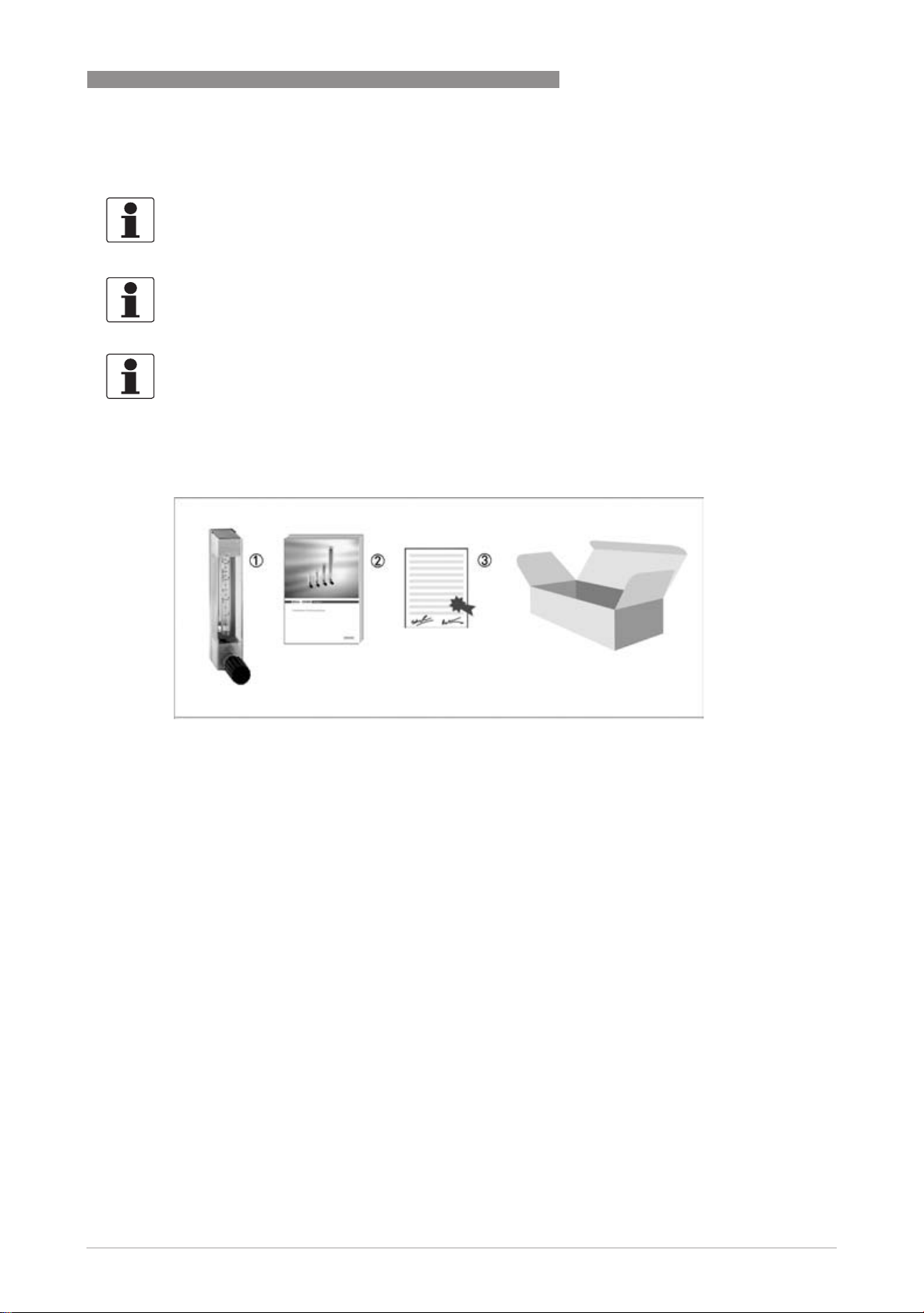
Figure 2-1: Scope of delivery
1 Flowmeter in the ordered version
2 Manual
3 Certificates, calibration certificate (supplied to order only)
www.krohne.com05/2011 - 4000302403 MA DK46-800-R03-en
9
Page 10
2 DEVICE DESCRIPTION
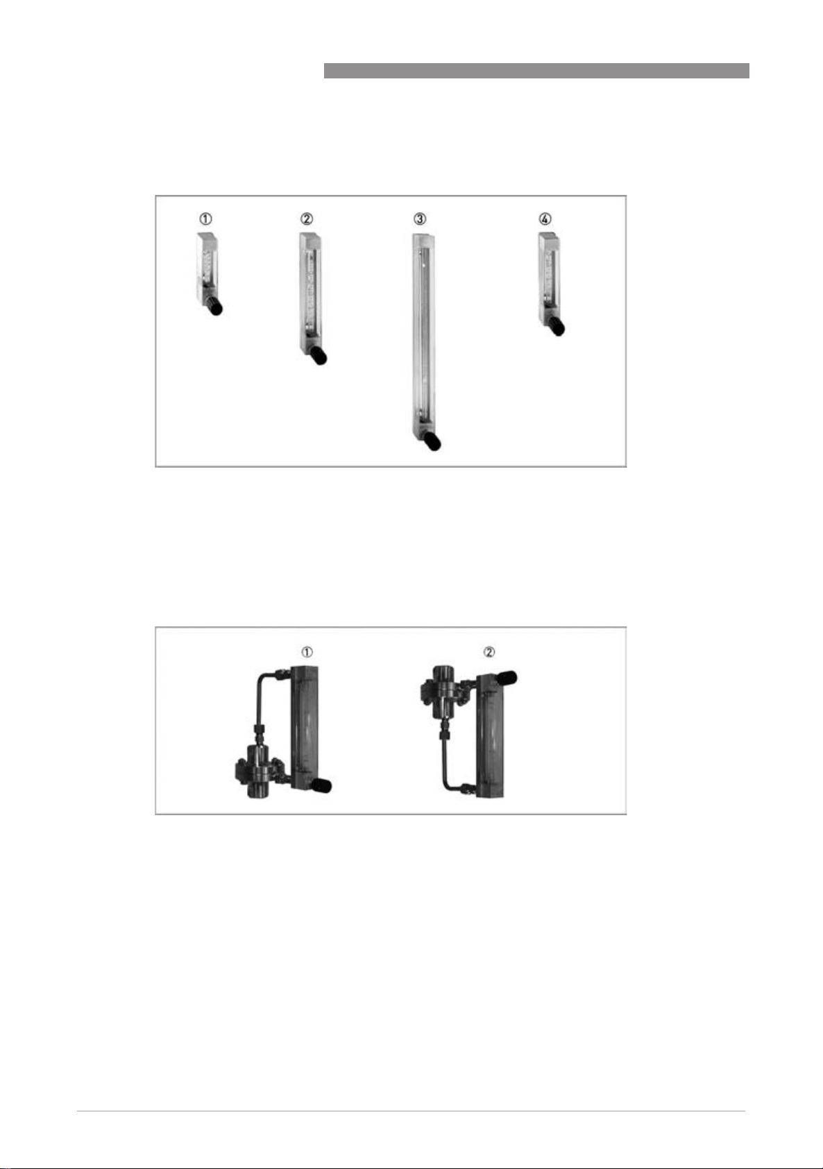
2.2 Device versions
DK46 - DK800
Figure 2-2: Device versions
1 DK46 with valve and an overall length of 111 mm
2 DK47 with valve and an overall length of 196 mm
3 DK48 with valve and an overall length of 346 mm
4 DK800 with valve and an overall length of 146 mm
Figure 2-3: DK47 with differential pressure regulators
1 DK47 with inlet pressure regulator
2 DK47 with outlet pressure regulator
10
www.krohne.com 05/2011 - 4000302403 MA DK46-800-R03-en
Page 11
DK46 - DK800
2.3 Nameplate
INFORMATION!
Look at the device nameplate to ensure that the device is delivered according to your order.
Check for the correct supply voltage printed on the nameplate.
DEVICE DESCRIPTION 2
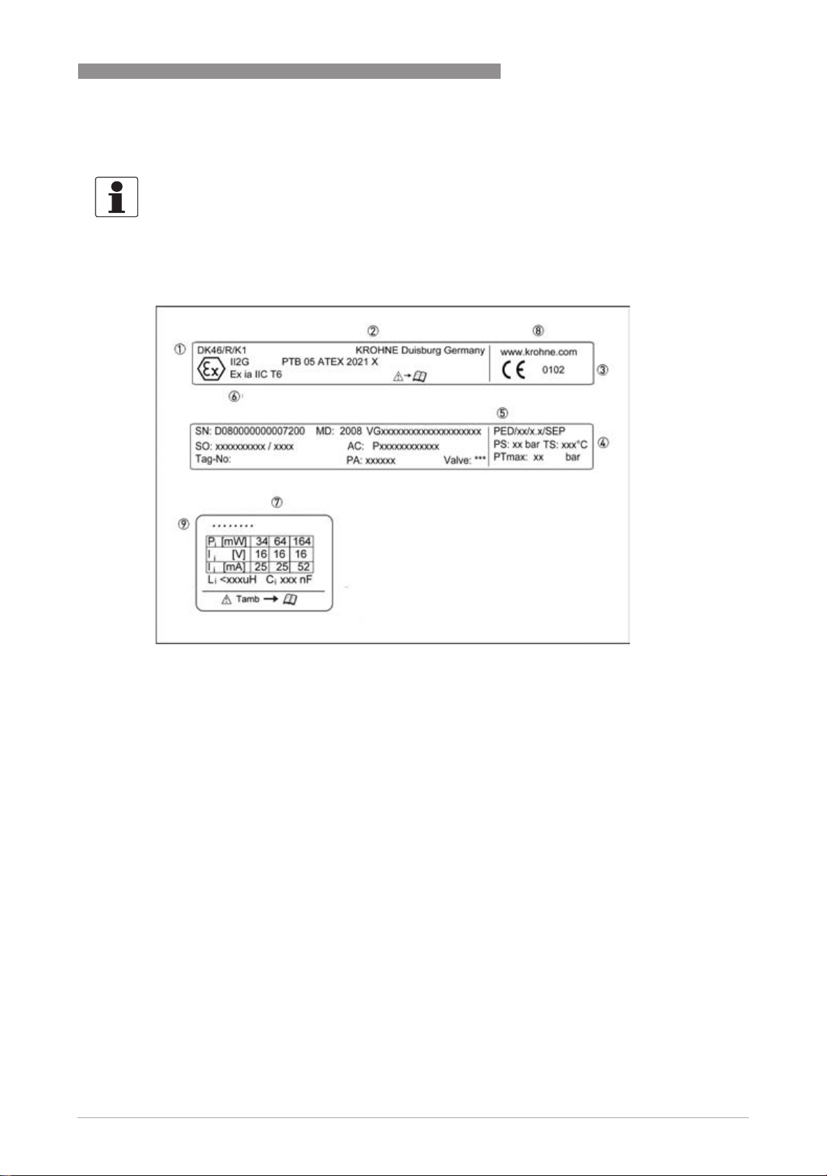
Figure 2-4: Nameplates (Examples)
1 Type of meter
2 Manufacturer
3 Appointed ATEX body
4 Design data: temperature & pressure rating
5 DGRL data
6 Ex data
7 Electrical connection data
8 KROHNE website
Additional markings on the measuring device
• SN - serial number
• SO - sales order / item
• Tag-No - Measuring point identifier
• MD - manufacturing date
• PA - KROHNE order
• Vx - product configurator code
• AC - article code
www.krohne.com05/2011 - 4000302403 MA DK46-800-R03-en
11
Page 12

2 DEVICE DESCRIPTION
2.4 Description code
The description code* consists of the following elements:
1 R - with integrated inlet pressure regulator (DKR46 only)
2 Device type:
46 - Overall length of measuring cone 65 mm
47 - Overall length of measuring cone 150 mm
48 - Overall length of measuring cone 300 mm
800 - Overall length of measuring cone 100 mm
3 Material for top and bottom fittings
N - brass
R - stainless steel
PV - PVDF
DK46 - DK800
4 Differential pressure regulators
RE - inlet pressure regulator
RA - outlet pressure regulator
5 K1 - one limit switch / K2 - two limit switches
* positions which are not needed are omitted (no blank positions)
12
www.krohne.com 05/2011 - 4000302403 MA DK46-800-R03-en
Page 13

DK46 - DK800
3.1 Notes on installation
INFORMATION!
Inspect the cartons carefully for damage or signs of rough handling. Report damage to the
carrier and to the local office of the manufacturer.
INFORMATION!
Check the packing list to check if you received completely all that you ordered.
INFORMATION!
Look at the device nameplate to ensure that the device is delivered according to your order.
Check for the correct supply voltage printed on the nameplate.
3.2 Storage
• Store the device in a dry and dust-free location.
• Avoid lasting direct exposure to the sun.
• Store the device in its original packing.
• The permissible storage temperature for standard devices is -40...+80°C / -40...+176°F.
INSTALLATION 3
www.krohne.com05/2011 - 4000302403 MA DK46-800-R03-en
13
Page 14

3 INSTALLATION
3.3 Installation conditions
3.3.1 Installation in the piping
CAUTION!
When installing the device in the piping, the following points must be observed:
•
The variable area flowmeter must be installed vertically (measuring principle). Flow direction
from bottom to top. For installation recommendations please refer also to VDI/VDE 3513
Sheet 3.
•
Before connecting, blow or flush out the pipes leading to the device.
•
Pipes for gas flow need to be dried before the device is installed.
•
Use connectors suitable for the particular device version.
•
Align the pipes axially with the connections on the measuring device so they are free of
stresses.
•
If necessary, support the piping to reduce vibrations being transmitted to the measuring
device.
•
Do not lay signal cables directly next to cables for the power supply.
DK46 - DK800
3.3.2 Panel mounting
Prepare the panel cutout as shown in the drawing (see chapter - Technical Data - Dimensions).
To mount in the panel, slightly loosen the two screws 1 on the front panel of the measuring
device. Insert the device into the panel cutout from the front, align and fasten with the two
screws 1.
14
www.krohne.com 05/2011 - 4000302403 MA DK46-800-R03-en
Page 15

DK46 - DK800
4.1 Safety instructions
DANGER!
All work on the electrical connections may only be carried out with the power disconnected. Take
note of the voltage data on the nameplate!
DANGER!
Observe the national regulations for electrical installations!
DANGER!
For devices used in hazardous areas, additional safety notes apply; please refer to the Ex
documentation.
WARNING!
Observe without fail the local occupational health and safety regulations. Any work done on the
electrical components of the measuring device may only be carried out by properly trained
specialists.
ELECTRICAL CONNECTIONS 4
INFORMATION!
Look at the device nameplate to ensure that the device is delivered according to your order.
Check for the correct supply voltage printed on the nameplate.
www.krohne.com05/2011 - 4000302403 MA DK46-800-R03-en
15
Page 16

4 ELECTRICAL CONNECTIONS
4.2 Limit switch
The flowmeters can be equipped with a maximum of two limit switches. The switching function of
the limit switch can be designed as monostable or bistable.
Monostable function: Switching pulse as float passes through switching point,
independent of direction of movement.
Bistable function: Stable changeover as float passes through switching point.
Example (bistable): Float above limit: Output "High"
Float below limit: Output "Low"
For switching patterns and electrical connection values of different limit switches, see -
Technical Data - Limit Switches
Connection of limit switch - 2 wire NAMUR
DK46 - DK800
1 Lower limit switch to terminal 1
2 Upper limit switch to terminal 2
The connection box includes an EMC filter unit.
Electrical connection limit switches - 2-wire NAMUR no terminal box
1 Limit switch (no terminal box)
2 Blue cable -
3 Brown cable +
4 External EMC filter
5 Receiver device
When connecting to an EMC filter, the ground terminal must be connected to the back rail of the
flowmeter.
Electrical connection limit switch - 3-wire (transistor)
16
bn - brown: supply voltage +
bk - black - switch
bu - blue: supply voltage -
www.krohne.com 05/2011 - 4000302403 MA DK46-800-R03-en
Page 17

DK46 - DK800
4.3 Limit switch settings
The following procedures are to be performed (DK../../K):
• Remove both clamping screws 1
• Slide the limit switch over the measuring glass
• Use the two clamping screws 1 to fasten the limit switch 3 to the back rail 2 of the
measuring device.
• Reinstall the protective cover following installation.
ELECTRICAL CONNECTIONS 4
For installation after the fact, the measuring glass must be removed. (refer to chapter entitled
"Service")
CAUTION!
When setting the limit switch, be careful to lay the cable so that it does not get damaged.
Avoid canting of the limit switch during installation: glass breakage
The connecting lead of the limit switch is guided through a hole in the base of the device and
sealed.
Observe the following for bistable limit switches with external EMC filters in separate DIN rail
housing:
The EMC filter unit and the back rail of the meter must be galvanically connected and grounded.
An isolation switching amplifier with intrinsically safe circuit controls is necessary to operate the
NAMUR limit switches.
www.krohne.com05/2011 - 4000302403 MA DK46-800-R03-en
17
Page 18

4 ELECTRICAL CONNECTIONS
4.4 Minimum clearance between two limit switches
Where two limit switches are used in one device and also where meters with limit switches are in
close proximity of each other, minimum clearances must be maintained in order to avoid mutual
influence of the switches.
DK46 - DK800
Minimum
clearance
1 16mm 0,63" 45mm 1,77"
2 6mm 0,236" 30mm 1,18"
NAMUR 2-wire transistor 3-wire
4.5 Switching performance
Limit switch NAMUR monostable:
Float outside limit switch: signal ≥3 mA
Float inside limit switch (centre): signal ≤1 mA
Limit switch NAMUR bistable:
Regardless of the position of the float: after passage 1 signal ≥3 mA
Prerequisite: the float is outside the limit switch.
INFORMATION!
For proper initialisation following power up, the NAMUR bistable limit switches should pass
through each of 1 and 2 once.
18
Limit switch 3-wire limit switch (transistor)
Independent of the position of the float: after passage 2 signal ≤1 V
Prerequisite: the float is outside the limit switch.
www.krohne.com 05/2011 - 4000302403 MA DK46-800-R03-en
Page 19

DK46 - DK800
4.6 Limit switch function reversal
The bistable limit switches can be changed from closers to openers.
The prefabricated connection cable must be long enough to do this.
When installing and setting, make sure the cable is not damaged when laid.
• Loosen terminal screw 1
• Turn tensioning screw 2 counter-clockwise to loosen
• Pull out the measuring glass along with the limit switch
• Turn limit switch 180°
• Install the measuring glass
• Tighten tensioning screw 2 by hand
• Use a 3mm pin to tighten tensioning screw by turning 4 or max. 5 times in 120° increments 3
in a clockwise direction.
ELECTRICAL CONNECTIONS 4
CAUTION!
To avoid breakage, the measuring glass must be positioned centrically between the gaskets.
Test the leak tightness by suitable means prior to start up.
www.krohne.com05/2011 - 4000302403 MA DK46-800-R03-en
19
Page 20

4 ELECTRICAL CONNECTIONS
4.7 Grounding connection
The measuring section is grounded on the back rail 1 (M4 thread). The connection guarantees
only an electrostatic connection of the device and does not comply with the requirements of
potential equalisation connection.
DANGER!
The grounding wire may not transfer any interference voltage.
Do not use this grounding wire to ground any other items of electrical equipment.
DK46 - DK800
4.8 Protection category
The limit switch with connection housing meets all requirements as per protection category IP
65.
Therefore it is essential to observe the following points:
• Use only original gaskets. They must be clean and free of any damage. Defective gaskets have
to be replaced.
• The electrical cables used must be undamaged and must comply with regulations.
• The cables must be laid with a loop 3 upstream of the measuring device to prevent water
from getting into the housing.
• The cable glands 2 must be tightened.
• Close the unused cable glands using blanking plugs 1.
20
DANGER!
After all servicing and maintenance work on the device, the specified protection category has to
be ensured again.
www.krohne.com 05/2011 - 4000302403 MA DK46-800-R03-en
Page 21

DK46 - DK800
5.1 Start-up
CAUTION!
When starting up the flowmeter, the following points must be observed:
•
•
•
•
•
•
•
•
•
START-UP 5
Compare the actual operating pressure and the process temperature of the system with the
specifications on the nameplate (PS and TS); these limits must not be exceeded.
Make sure materials are compatible.
Close the needle valve at the flowmeters.
Slowly open the shut-off valve upstream and downstream of the flowmeter.
When measuring liquids, vent the pipes carefully.
When measuring gases, increase pressure slowly.
void float impact (e.g. caused by solenoid valves), as this is likely to damage the measuring
section or float.
Open needle valve at the flowmeters and set the required flow rate.
The top edge of the float marks the reading line for flow values:
Figure 5-1: Reading edge
1 Reading edge
2 Floatform AIII
3 Floatform ball
www.krohne.com05/2011 - 4000302403 MA DK46-800-R03-en
21
Page 22

6 SERVICE
6.1 Maintenance
Within the scope of routine maintenance of the system and pipings, the flowmeter should also be
inspected for signs of dirt, corrosion, mechanical wear and leaks, as well as damage to the
measuring device.
We advise that inspections be carried out at least once per year.
The device must be removed from the piping before cleaning.
CAUTION!
Pressurized pipes must be depressurized before removing the device.
In the case of devices used for measuring aggressive or hazardous media, appropriate safety
precautions must be taken with regard to residual liquids in the measuring unit.
Always use new gaskets when reinstalling the device in the pipings.
CAUTION!
The packing seal for the valve may have to be adjusted during the service life. The lock nut must
be tightened for this.
Apply a tightening torque of not more than 5 Nm.
DK46 - DK800
CAUTION!
Valves that have not been used for a longer period of time may exhibit a higher actuating torque.
22
www.krohne.com 05/2011 - 4000302403 MA DK46-800-R03-en
Page 23

DK46 - DK800
6.2 Changing the measuring cone
• Close the valves located upstream and downstream of the device.
• Close needle valve
• Push protective cover upwards and remove towards the front
• Turn tensioning screw 1 counter-clockwise to loosen
Devices with a top and bottom fitting made of PVDF (DK.../PV) have a tensioning screw in the
device head (6mm Allen key). This can be loosened with approx. 1 full turn.
The measuring glass can be removed to the front.
SERVICE 6
Figure 6-1: Maintenance
CAUTION!
Residual liquid or gas may leak out!
• Install in the reverse order
• Tighten tensioning screw 1 by hand
• Use a 3mm pin to tighten tensioning screw 4 or max. 5 times in 120° increments 2 in a
clockwise direction.
CAUTION!
To avoid breakage, the measuring glass must be positioned centrically between the gaskets.
Test the leak tightness by suitable means prior to start up.
www.krohne.com05/2011 - 4000302403 MA DK46-800-R03-en
23
Page 24

6 SERVICE
6.3 Spare parts availability
The manufacturer adheres to the basic principle that functionally adequate spare parts for each
device or each important accessory part will be kept available for a period of 3 years after
delivery of the last production run for the device.
This regulation only applies to spare parts which are subject to wear and tear under normal
operating conditions.
6.4 Availability of services
The manufacturer offers a range of services to support the customer after expiration of the
warranty. These include repair, maintenance, technical support and training.
INFORMATION!
For more precise information, please contact your local representative.
6.5 Returning the device to the manufacturer
DK46 - DK800
6.5.1 General information
This device has been carefully manufactured and tested. If installed and operated in accordance
with these operating instructions, it will rarely present any problems.
CAUTION!
Should you nevertheless need to return a device for inspection or repair, please pay strict
attention to the following points:
•
Due to statutory regulations on environmental protection and safeguarding the health and
safety of our personnel, manufacturer may only handle, test and repair returned devices that
have been in contact with products without risk to personnel and environment.
•
This means that the manufacturer can only service this device if it is accompanied by the
following certificate (see next section) confirming that the device is safe to handle.
CAUTION!
If the device has been operated with toxic, caustic, flammable or water-endangering products,
you are kindly requested:
•
to check and ensure, if necessary by rinsing or neutralizing, that all cavities are free from
such dangerous substances,
•
to enclose a certificate with the device confirming that is safe to handle and stating the
product used.
24
www.krohne.com 05/2011 - 4000302403 MA DK46-800-R03-en
Page 25

DK46 - DK800
6.5.2 Form (for copying) to accompany a returned device
Company: Address:
Department: Name:
Tel. no.: Fax no.:
Manufacturer's order no. or serial no.:
The device has been operated with the following medium:
SERVICE 6
This medium is: water-hazardous
toxic
caustic
flammable
We checked that all cavities in the device are free from such
substances.
We have flushed out and neutralized all cavities in the
device.
We hereby confirm that there is no risk to persons or the environment through any residual media
contained in the device when it is returned.
Date: Signature:
Stamp:
6.6 Disposal
CAUTION!
Disposal must be carried out in accordance with legislation applicable in your country.
www.krohne.com05/2011 - 4000302403 MA DK46-800-R03-en
25
Page 26

7 TECHNICAL DATA
7.1 Operating principle
The flowmeter operates on the float measuring principle
The measuring unit consists of a glass cone in which a float can move freely up and down. The
medium flows through the flowmeter from bottom to top.
The float adjusts itself so that the buoyancy force A, acting on it, the form drag W and its weight G
are in equilibrium: G = A + W.
DK46 - DK800
Figure 7-1: Operating principle
The height of the float is read on the scale of the measuring glass and indicates the flow rate.
The top edge of the float marks the reading line for flow values.
26
www.krohne.com 05/2011 - 4000302403 MA DK46-800-R03-en
Page 27

DK46 - DK800
7.2 Technical data
INFORMATION!
•
The following data is provided for general applications. If you require data that is more
relevant to your specific application, please contact us or your local representative.
•
Additional information (certificates, special tools, software,...) and complete product
documentation can be downloaded free of charge from the website (Download Center).
Measuring system
Application range Flow measurement of liquids and gases
Operating method / measuring principle Variable area measuring principle
Measurement
Primary measured value Float position
Secondary measured value Operating and standard volumetric flow
Measuring accuracy
Directive VDI / VDE 3513, sheet 2 (qG = 50%)
DK46 4.0%
DK47 2.5%
DK48 1.0%
DK800 2.5%
TECHNICAL DATA 7
Operating conditions
Temperature
Temperature
TemperatureTemperature
Max. operating temperature TS -5...+100°C / +23...+212°F
Pressure
Pressure
PressurePressure
Operating pressure PS Pressure Equipment Directive 97/23/EC
Test pressure PT Pressure Equipment Directive 97/23/EC
Max. permitted operating gauge pressure PS at TS = 100°C / 212°F:
DK…/R (stainless steel top and bottom fittings ) 10bar / 145psig 1
DK…/N (brass top and bottom fittings ) 10bar / 145psig 1
DK…/PV (PVDF top and bottom fittings ) 4bar / 58psig
Installation conditions
Inlet and outlet None
1 higher pressures upon request
www.krohne.com05/2011 - 4000302403 MA DK46-800-R03-en
27
Page 28

7 TECHNICAL DATA
Materials
Top fitting, bottom fitting CrNi steel 1.4404 / 316 L, nickel-plated brass, PVDF 1
Top fitting, bottom fitting (optional)
Measuring tube Borosilicate glass
Float (ball) CrNi steel 1.4401 / 316
Float options
Float AIII CrNi steel 1.4404 / 316 L, Aluminium, Polypropylene (PP)
Metering unit CrNi steel 1.4571 / 316 Ti
Valve spindle CrNi steel 1.4404 / 316 L
Gaskets (standard) PTFE / FPM
Gaskets (optional) PTFE / FFKM, PTFE / EPDM
Gaskets (optional) EPDM, FFKM
Protective cover Polycarbonate
1 top and bottom fittings made of PVDF not on DK48
Hastelloy
®
Glass, POM, titanium, Hastelloy® C4
DK46 - DK800
Temperatures
Max. temperature of medium T
Max. T
Max. ambient temperature T
Max. T
Other temperatures on request.
with limit switches -5...+65°C +23...+149°F
m
with limit switches -20...+65°C -4...+149°F
amb.
amb.
m
-5...+100°C +23...+212°F
-20...+100°C -4...+212°F
28
www.krohne.com 05/2011 - 4000302403 MA DK46-800-R03-en
Page 29

DK46 - DK800
Technical Data Limit Switches
1 For devices with the valve at the top (at the outlet) and devices with outlet pressure regulators, the function is inverted!
TECHNICAL DATA 7
Terminal connection Connection box M16 x 1.5
Clamping range 3...7mm - 0.12...0.28"
Limit switch I7R2010-NL I7R2015-NL I7R2010-N I7R2015-N RB15-14-E2
RC10-14-N3 RC15-14-N3 RC10-14-N0 RC15-14-N0
Ring diameter 10mm 15mm 10mm 15mm 15mm
Switching function bistable bistable monostable monostable bistable
NAMUR yes yes yes yes no
Connection technology 2-wire 2-wire 2-wire 2-wire 3-wire
Nominal voltage U
Current consumption 1mA passage ↓ 1 3mA - float outside
Current consumption 3mA passage ↑ 1 1mA - float in the limit
Operating voltage U
Operating current I 0…100mA
No load current I 20mA
Output Ua - passage ↓ ≤1VDC 1
Output Ua - passage ↑ ≥U
0
ext.
8VDC 8VDC 8VDC 8VDC
switch
10…30VDC
–3VDC 1
b
Field of application for limit switches
DK46, DK47, DK800 DK48
Float Ring diameter Cone no. Ring diameter
Ø 4mm / 0.158" 10mm / 0.394” G13.11 -
Ø 6mm / 0.236" 15mm / 0.591” G14.06 -
Ø 8mm / 0.315" - G14.08 -
G15.07 10mm / 0.394”
G15.09 10mm / 0.394”
G15.12 10mm / 0.394”
G16.08 10mm / 0.394”
G16.12 10mm / 0.394”
G17.08 15mm / 0.591”
G17.12 15mm / 0.591”
G18.06 -
G18.08 -
G18.12 -
The limit switches with ring diameters of 15mm as max. contact can only be used up to 60l/h -
15.8GPH water or 2400l/h - 89,3SCFH air (outer diameter of the measuring glass).
www.krohne.com05/2011 - 4000302403 MA DK46-800-R03-en
29
Page 30

7 TECHNICAL DATA
7.3 Dimensions and weights
Dimensions
DK46 - DK800
Device a b
d f approx.
± 0.25
[mm] ["] [mm] ["] [mm] ["] [mm] ["]
DK46 111 4.37 90 3.55 45 1.77 82 3,2
DKR46 136 5,36 90 3,55 - - 125 4,92
DK800 146 5.75 125 4.92 80 3.15 82 3,2
DK47 196 7.72 175 6.89 130 5.12 82 3,2
DK48 346 13.6 325 12.8 280 11.0 82 3,2
c = 4,3mm / 0,169"
e = 33mm / 1,3"
f ca. 82mm / 3,2"
g = 28mm / 1,1"
Dimensions of panel cutout and faceplate
Device a c
[mm] ["] [mm] ["]
DK46 128 5.04 145 5.71
DK800 163 6.42 180 7.09
DK47 213 8.39 230 9.06
DK48 363 14.3 380 15.0
b = 32mm / 1.26" d = 40mm / 1.58"
e = 27.5mm / 1.08"
30
www.krohne.com 05/2011 - 4000302403 MA DK46-800-R03-en
Page 31

DK46 - DK800
Weights
Process connection
1 other connection upon request
TECHNICAL DATA 7
DK46 DK800 DK47 DK48
[kg] [lb] [kg] [lb] [kg] [lb] [kg] [lb]
Weight 0.4 0.88 0.5 1.1 0.6 1.3 0.7 1.5
Weights with regulator 2.1 4.6 2.2 4.9 2.3 5.1 2.4 5.3
Standard ¼" NPT internal thread
Options G¼, Ermeto 6 or 8, tube connection 6mm or 8mm, Dilo, Gyrolok, Swagelok 1
www.krohne.com05/2011 - 4000302403 MA DK46-800-R03-en
31
Page 32

7 TECHNICAL DATA
DK46 - DK800
7.4 Measuring ranges
Measuring ranges DK(R)46 - DK47 - DK800
Measuring span: 10 : 1 Float forms:
Declaration of flow: Values = 100%
Water: 20°C [68°F]
Air: 20°C [68°F], 1,2 bar abs. [17.4 psia]
Float material: CrNi steel Ball AIII 4-H
Water Air
Float Ø DK46 DK47 DK800 DK(R)46 DK47 DK800
[mm] ["] [l/h] [GPH] [l/h] [GPH] [l/h] [GPH] [Nl/h] SCFH [Nl/h] SCFH [Nl/h] SCFH
40.1582.5 0.65 - - 2.5 0.65 5 1 0,22 1 - - 5 1 0,18 1
- - - - - - 8 1 0,3 1 - - 8 1 0,3 1
- - - - - - 16 0,6 16 1 0,6 16 0,6
- - - - - - 40 1,5 40 1,5 40 1,5
- - - - - - 60 2,2 100 3,8 60 2,2
6 0.236 5 1.3 5 1.3 5 1.3 100 3,8 250 9,5 100 3,8
12 3.0 12 3.0 12 3.0 250 9,5 500 19 250 9,5
25 6.5 25 6.5 25 6.5 500 19 800 30 500 19
40 11 40 11 40 11 800 30 - - 800 30
60 2 16 2 60 16 60 16 1200 2 45 2 - - 1000 38
100 2 25 2 100 25 100 25 - - - - 1800 65
- - - - 120 30 - - - - 2400 90
- - - - 160 42 - - - - 3000 110
- - - - - - - - - - 4000 140
- - - - - - - - - - 5000 180
8 0.315 120 2 30 2 - - - - - - - - - -
160 2 42 2 - - - - - - - - - -
1 with float AIII 4-H
2 not for DKR46
32
INFORMATION!
The operating pressure should be at least twice the pressure loss for liquids, and at least 5 times the
pressure loss for gases! The specified pressure drops are valid for water and air at maximum flow rate.
Other flow ranges on request. Conversion of other media or operating data (pressure, temperature, density,
viscosity) is performed using the calculation method in accordance with VDI /VDE Directive 3513
Reference condition for gas measurements:
Reference condition for gas measurements:
Reference condition for gas measurements:Reference condition for gas measurements:
The flow measurement of gases are refered to
3
Nl/h or Nm
/h: Volume flow in Normal state 0°C, 1.013 bar abs. (DIN 1343)
SCFM or SCFH: Volume flow in Standard state 15°C, 1.013 bar abs. (ISO 13443)
www.krohne.com 05/2011 - 4000302403 MA DK46-800-R03-en
Page 33

DK46 - DK800
TECHNICAL DATA 7
Measuring ranges DK48
Measuring span: 10 : 1 Float form:
Declaration of flow: Values = 100%
Water: 20°C [68°F]
Air: 20°C [68°F], 1,013 bar abs. [14.7 psia]
AIII
Water Air
Material Stainless Steel Polypropylene (PP) Aluminium Stainless Steel
Cone no. [l/h] [GPH] [Nl/h] [SCFH] [Nl/h] [SCFH] [Nl/h] [SCFH]
G 13.11 1 0.4 0.1 - - 7 0.25 16 0.6
G 14.06 0.6 0.16 - - 12 0.45 25 0.95
G 14.08 1 0.25 - - 20 0.75 40 1.5
G 15.07 1.6 0.4 - - 30 1.1 60 2.2
G 15.09 2.5 0.65 - - 40 1.5 90 3.5
G 15.12 4 1.0 - - 60 2.2 140 5.0
G 16.08 6 1.6 - - 100 3.7 200 7.5
G 16.12 10 2.5 - - 160 6.0 300 11
G 17.08 16 4.0 - - 250 9.0 500 19
G 17.12 25 6.5 - - 400 15 800 30
G 18.06 40 10 400 15 600 22 1200 45
G 18.08 63 16 600 22 1000 37 2000 75
G 18.12 100 25 1000 37 1600 60 3000 110
1 reduced accuracy : 2.5%
INFORMATION!
The operating pressure should be at least twice the pressure loss for liquids, and at least 5
times the pressure loss for gases! The specified pressure drops are valid for water and air at
maximum flow rate. Other flow ranges on request. Conversion of other media or operating data
(pressure, temperature, density, viscosity) is performed using the calculation method in
accordance with VDI /VDE Directive 3513
Reference condition for gas measurements:
Reference condition for gas measurements:
Reference condition for gas measurements:Reference condition for gas measurements:
The flow measurement of gases are refered to
3
Nl/h or Nm
/h: Volume flow in Normal state 0°C, 1.013 bar abs. (DIN 1343)
SCFM or SCFH: Volume flow in Standard state 15°C, 1.013 bar abs. (ISO 13443)
www.krohne.com05/2011 - 4000302403 MA DK46-800-R03-en
33
Page 34

7 TECHNICAL DATA
Valves
Declaration of flow: Values = 100%
Water: 20°C [68°F]
Air: 20°C [68°F], 1,013 bar abs. [14.7 psia]
Valve spindle Water Air Kv Cv
DK46 - DK800
Max. flowrate Valve characteristic value
Ø [mm] Ø [inches] [Nl/h] [GPH] [Nl/h] [SCFH]
1 0.039 5 1.3 100 3,7 0.018 0,02
2.5 0.98 50 13 1000 37 0.15 0,17
4.5 0.177 160 42 4300 160 0.48 0,55
[m3/h]
[GPM]
Valve characteristics
Spindle Ø 1.0mm - 0,039" Spindle Ø 2.5mm - 0,098"
Spindle Ø 4.5mm - 0,177"
34
1 Flow, air
2 Flow, water
3 Spindle revolution n
www.krohne.com 05/2011 - 4000302403 MA DK46-800-R03-en
Page 35

DK46 - DK800
7.5 Differential pressure regulators
Differential pressure regulators are used to guarantee constant flow during fluctuating inlet and
outlet pressure. Minimum pressures are required to operate the regulators (see regulator
characteristics).
Differential pressure regulators are not equivalent to pressure reducing valves!
1 Inlet pressure regulators, type RE, NRE
The regulators keep the flow rate constant in the case of a variable inlet pressure and a constant
outlet pressure.
TECHNICAL DATA 7
Example - inlet pressure
regulator RE1000:
The flow rate in the meter remains constant with a fluctuating inlet pressure greater than 0.5 bar.
Current flow rate: 1000l/h air
Outlet pressure p2 constant: 1.013 bar abs.
2 Outlet pressure regulator, type RA, NRA
The regulators keep the flow rate constant in the case of a constant inlet pressure and a variable
outlet pressure. There must be a pressure differential between the inlet and the outlet pressure
for the outlet pressure regulator to function. The inlet pressure p1 must always be greater than
the outlet pressure p2.
Example - outlet pressure
regulator NRA 800
Current flow rate: 800l/h air
Inlet pressure constant: 6 bar
The flow rate in the meter remains constant with a fluctuating outlet pressure of 0...5.5 bar.
Regulator characteristics
1 Inlet pressure regulators, type RE and NRE 2 Outlet pressure regulators, type RA and
NRA
www.krohne.com05/2011 - 4000302403 MA DK46-800-R03-en
35
Page 36

7 TECHNICAL DATA
Control range
Declaration of flow: Values = 100%
Water: 20°C [68°F]
Air: 20°C [68°F], 1,013 bar abs. [14.7 psia]
Inlet pressure regulator 1
[l/h] [GPH] [Nl/h] [SCFH] p1 [bar] p1 [psig]
RE-1000 ...40 ...11 ...1000 ...37 0.5 7,25
RE-4000 ...80 ...20 ...2000 ...75 1 14,5
...100 ...25 …3000 ...110 1.5 21,8
...160 ...42 ...4000 ...150 2 29
NRE-100 ...2.5 ...0.6 ...100 ...3,7 0.1 1,45
NRE-800 - - …250 ...9,0 0.1 1,45
- - …800 ...30 0.2 2,9
...25 ...6.60 - - 0.4 5,8
DK46 - DK800
Max. flowrate
Water Air Min. inlet pressure
Outlet pressure regulator 2
Max. flowrate
Water Air Min. pressure diff. *
[l/h] [GPH] [Nl/h] [SCFH] Δp [bar] Δp [psig]
RA-1000 ...40 ...11 ...1000 ...37 0,4 5,8
RA-4000 ...100 ...25 …2000 ...75 1,2 17,4
- - ...3000 ...110 1,2 17,4
...160 ...42 ...4000 ...150 1,5 21,8
NRA-800 ...1 ...0.25 ...250 ...9,0 0,05 0,73
- - ...500 ...19 0,1 1,45
- - …800 ...30 0,2 2,9
...25 ...6.6 - - 0,4 5,8
Table 7-1: * Pressure difference between inlet and outlet pressure
Reference condition for gas measurements:
Reference condition for gas measurements:
Reference condition for gas measurements:Reference condition for gas measurements:
The flow measurement of gases are refered to
3
Nl/h or Nm
SCFM or SCFH: Volume flow in Standard state 15°C, 1.013 bar abs. (ISO 13443)
/h: Volume flow in Normal state 0°C, 1.013 bar abs. (DIN 1343)
36
www.krohne.com 05/2011 - 4000302403 MA DK46-800-R03-en
Page 37

DK46 - DK800
Technical data, differential pressure regulator
1 other connections on request
2 higher pressures on request
3 higher temperatures on request
4 other materials on request
TECHNICAL DATA 7
Standard connection ¼" NPT
Optional Serto, Ermeto 6 or 8, tube nozzle 6mm or 8mm,Dilo, Gyrolok, Swagelok,
Max. operating gauge
pressure PS
Product temperature TS = 100°C / 212°F 3
Material CrNi steel 1.4404
Gasket PTFE 4
Membrane PTFE filled with carbon / graphite
O-ring FPM 4
G¼ 1
10 bar / 145psig
4 bar / 58psig for DK.../PV 2
www.krohne.com05/2011 - 4000302403 MA DK46-800-R03-en
37
Page 38

7 TECHNICAL DATA
Dimensions with the differential pressure regulator
DK46 - DK800
a
b c d e f
approx.
[mm] ["] [mm] ["] [mm] ["] [mm] ["] [mm] ["] [mm] ["]
DK46 210 8.27 163 6.42 70 2.76 19 0.75 39 1.54 90 3.55
DK47 210 8.27 233 9.18 70 2.76 19 0.75 39 1.54 90 3.55
DK48 210 8.27 383 15.1 70 2.76 19 0.75 39 1.54 90 3.55
DK800 210 8.27 183 7.21 70 2.76 19 0.75 39 1.54 90 3.55
1 DK with inlet pressure regulator 2 DK with outlet pressure regulator
approx.
38
www.krohne.com 05/2011 - 4000302403 MA DK46-800-R03-en
Page 39

DK46 - DK800
NOTES 8
www.krohne.com05/2011 - 4000302403 MA DK46-800-R03-en
39
Page 40

KROHNE product overview
• Electromagnetic flowmeters
• Variable area flowmeters
• Ultrasonic flowmeters
• Mass flowmeters
• Vortex flowmeters
• Flow controllers
• Level meters
• Temperature meters
• Pressure meters
• Analysis products
• Measuring systems for the oil and gas industry
• Measuring systems for sea-going tankers
Head Office KROHNE Messtechnik GmbH
Ludwig-Krohne-Str. 5
D-47058 Duisburg (Germany)
Tel.:+49 (0)203 301 0
Fax:+49 (0)203 301 10389
info@krohne.de
The current list of all KROHNE contacts and addresses can be found at:
© KROHNE 05/2011 - 4000302403 MA DK46-800-R03-en - Subject to change without notice.
www.krohne.com
 Loading...