

Page 1
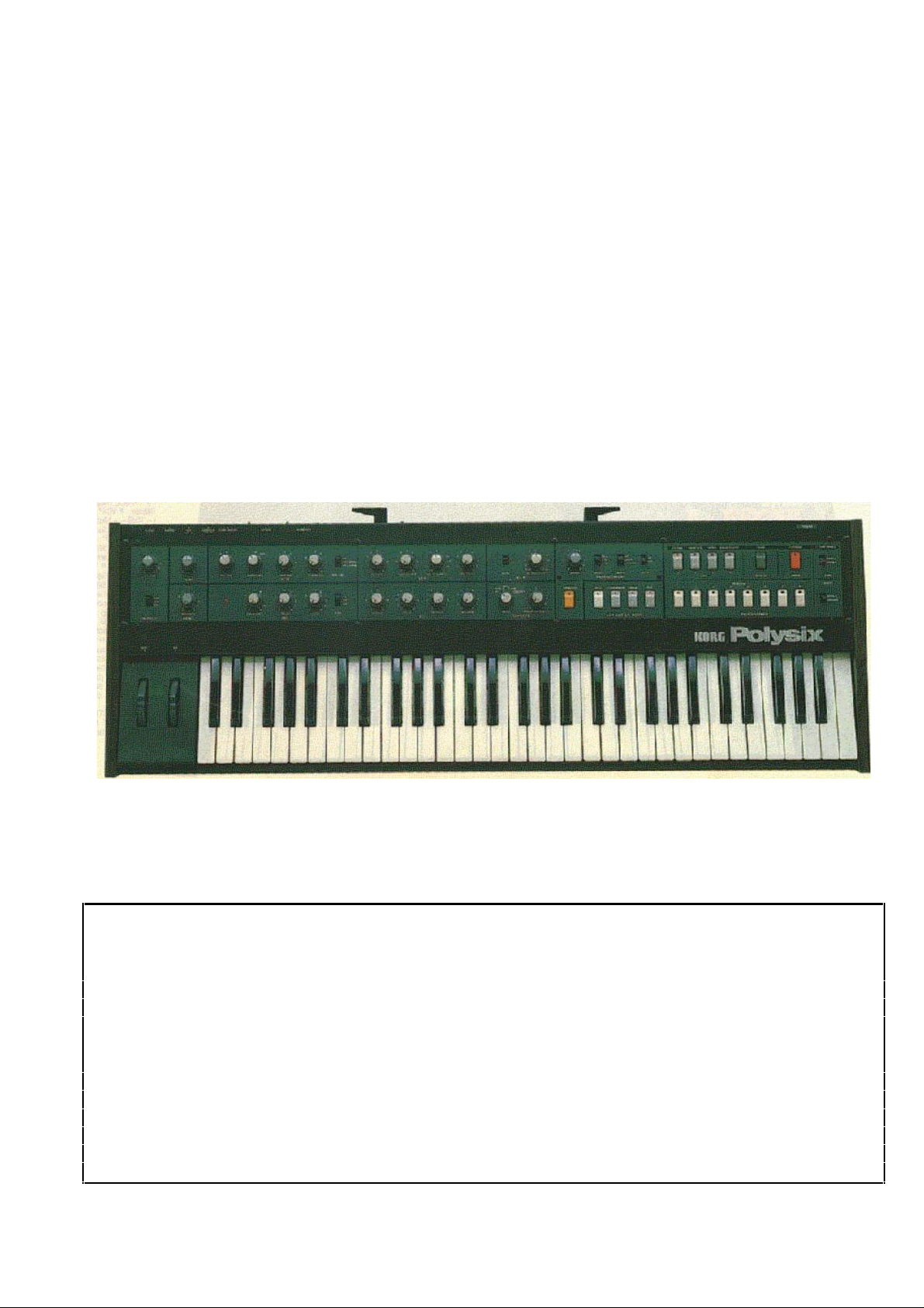
KORG POLYSIX
PROGRAMMABLE POLYPHONIC SYNTHESIZER
Owner’s Manual
Congratulations and thank you for purchasing the new Korg PS-6 "Polysix" Programmable Polyphonic
Synthesizer.
This versatile six-voice synthesizer offers the wide range of sounds and enormous ease of use that only a
programmable synthesizer can offer, at a revolutionary price.
Handling precautions
• Always be sure to use the correct AC line voltage. If line voltage is 90% or less of rated voltage, S/N ratio
and stability will suffer. If you have any reason to believe the AC voltage is too low, have It checked with a
voltmeter before you turn on the power supply switch.
• Do not use any type of plug except for standard phone plugs (guitar type) in the KORG POLYSIX input and
output jacks.
• Avoid using or storing your KORG POLYSIX in very hot, cold, or dusty places.
Important note
Because this unit em ploys a mi croprocessor, abnorm al perf ormanc e may occur if you switch the power on too
soon after turning it of f . S hould t his occur, turn off the power, wait about ten seconds, then t urn the power back on
again.
1
Page 2

Features
32 programs stored in memory allow the user to create his own sounds for instantaneous recall at the push of a
button.
Full edit capabilities allow the user to make temporary changes to any program, and to move programs about in
memory.
Rapid, 8-second Cassette Tape Interface capabilities provides unlimited additional program storage, allowing you
to create program libraries for later use.
Both UNISON and POLY modes, to create incredibly fat six-VCO soloing and bass sounds as well as versatile six
voice polyphonic sounds.
Built-in full featured ARPEGGIATOR, with 3 selectable patterns and ranges, and with automatic "Latch" mode.
CHORD MEMORY memorizes intervals and chords, to produce exciting parallel harmonies by depressing single
keys. Memorized chords can be arpeggiated as well. HOLD sustains notes and chords indefinitely.
Programmable Modulation and Chorus/Ensemble effects create rich, fat sounds.
Lightweight 11.5kg instrument with 5-octave, 61 note keyboard plus Pitch Bend and Mod Wheels, for expressive
playing.
2
Page 3
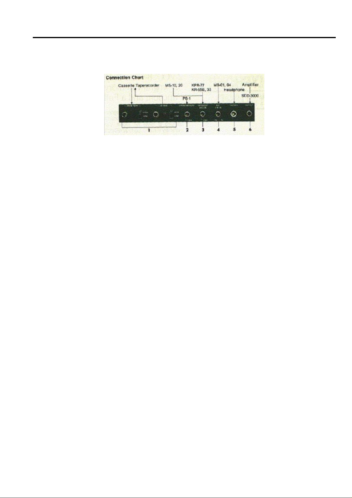
Connections
Rear panel facilities
1) FROM TAPE TO TAPE
For connecti on to a tape recorder. This int erfac e lets you store unli mi ted sets of progr ams on tape. T hese can
then be loaded back into the synthesizer’s programmer as needed ev en in the middl e of a set. Connect FROM
TAPE to the recorder’s output jack (li ne out, earphone, or headphone terminal). Connect TO TAPE to the tape
recorder’s input jack (line in, m ic in, etc.) . Set switches to HIGH or LOW positions as needed to matc h recorder
input and output levels. HIGH is line or earphone level; LOW is microphone level.
2) CHORD MEMORY
Foot switch (S-1, PS-1, etc.) i nput jack for rem ote control of CHO RD MEMORY, so you do not have to press
the key assign mode switch. Par t icularly useful for putting chords in the memory when you ar e using both hands to
finger t he chord. A chord of up t o six notes can be m em oriz ed and t hen t he sam e str ucture can be reproduced by
playing single keys.
3) ARPEGGIO TRIG IN
Lets you use an external devi ce to control arpeggio tem po. A trigger out put from a rhythm box , sequencer, or
synthesizer may be connec ted to this jack. The tri gger should be negative- going (short to ground) . There is an
internal high impedance pullup to +5V.
4) VCF fcM IN
For external cont rol over VCF cutof f f requency (using MS-01, -04 f ootpedal , et c.). T his v ari es the ti m bre of the
sound, and permits "waa-waa" pedal effects when VCF is set at medium-high resonance.
5) PHONES
The phone jack is not silences by setti ng the front panel "OUT PUT" switch to OFF. This makes checking or
modify sound programs less obtrusive during recording or performance.
6) OUTPUT
High level or low level, controlled by front panel switch.
3
Page 4
Features and Functions
12345
PROGRAMMABLE CONTROLS (CAN BE STORED IN MEMORY)
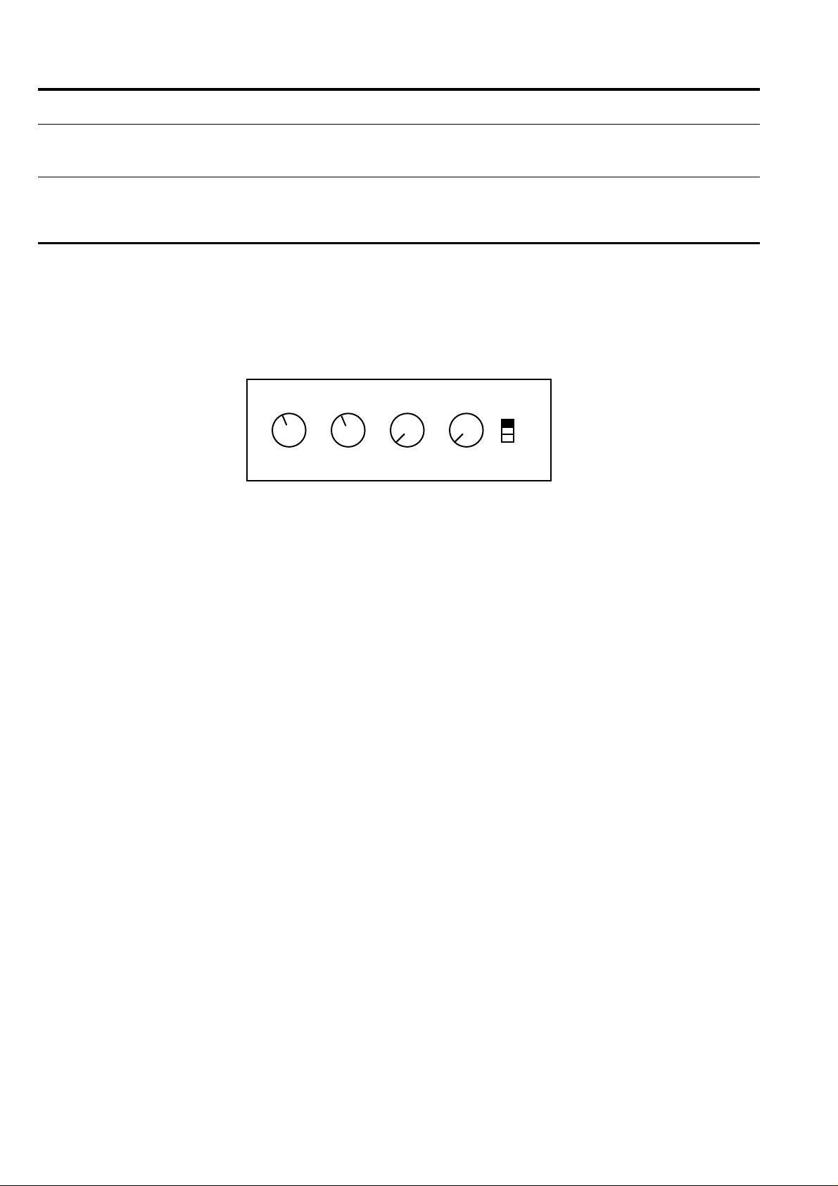
VCO
The Voltage Cont r olled Oscillator (VCO) is the basic sound source for the synthesizer. There are 6 VCOs in the
Polysix, one per voice. The VCO waveform you select has a large effect on the timbre or tone quality of a
particular sound. The VCO may be set to operate in several different octaves, extending the range of the
keyboard. Pulse width modulation and Sub O SC tones are included, allowing a wide range of fat, satisfying sounds
to be produced.
OFF
1 OCT
2 OCT
OCTAVE WAVEFORM PW/PWM PWM SPEED SUB OSC
VCO
1) OCTAVE
This control has thr ee settings, 16’, 8’, and 4’. At the 8’ setting, t he mi ddle A on the keyboar d produces A440
(with Tune control set properly). 16’ and 4’ settings produce sound one octave lower and one octave higher,
respectively. The keyboard is therefore extended to the equivalent of a 7 octave range.
2) WAVEFORM
A. Sawtooth
This waveform is rich in both ev en and odd harmonic overtones. Because of this, the VCF can be used to
"shape" the tone color ov er a wide range by selectiv ely emphasizing di fferent harmonics of the waveform (see
VCF section for more details). Sawtooth waveforms are good for bass, strings, brass, and many other sounds.
B. PW/PWM (Pulse Width/Pulse Width Modulation)
These settings produce v ari ous types of r ectangul ar wav ef orm s, such as square waves, pulse wav es, "chorus",
etc., depending on t he setting of the PW/PWM and PWM SPEED controls. An extremely wide range of sounds are
available using these controls.
• PW Waveform
The width, or "duty cycl e" of the VCO wavef orm may be v aried manually using the PW/ PWM cont rol (PW M
SPEED has no effect in this position). At 0, t he VCO waveform is square wave (50% duty cycle), and possesses
the typical dull and "hollow" sound of the clarinet (only odd harmonics are present). Advancing the PW/PWM
control reduces the duty cycle, and hence the width of the VCO waveform . This produces a dramatic shif t i n the
tone qualit y towards a brighter and more "nasal ly" sound simil ar to oboe or harpsichord. At 8 or abov e t he pulse
width becomes so narrow as to collapse, which produces sound and in ef fect shuts off the VCOs. This is useful
when the VCFs are used as sound sources in their self oscillating mode.
Note: The SUB OSC tone is not shut off when the VCO is shut off due to zero pulse width.
• PWM Waveform
The width of t he VCO pulse wav eform is conti nuously changed, or " modul ated" by a v ariabl e speed oscillator.
This creates a fat "chorusing" t ype of sound, sim il ar to m ulti ple oscillators due to the constantly shif ting harm onic
balance. The PW /PWM control now determines the depth of the effect. At 0, there is no modulation (constant
square wave). Between 8 and 10, m odulation dept h is so great that the VCO shuts of f part of t he tim e (because
pulse width becomes 0 for part of each cycle). The speed of the ef fect is control led by the PWM SPEED knob.
The PWM oscillator is completely separate from the MG oscillator used for vibrato (see MG section), thus allowing
vibrato and PWM effects to occur simultaneously.
4
Page 5

3) PW/PWM
This controls the pulse width of the PW waveform, and the modulation depth of the PWM waveform (see
above).
4) PWM SPEED
This controls the speed of the modulation eff ect in the PWM wavef orm (see abov e) . It has no ef f ect on t he PW
waveform.
5) SUB OSC
This switch allows you to add a second tune either one octav e or two octaves below the VCO pi tch. This is
useful for produci ng fatter and full er sounds, particularly wit h solo or base Unison playing, organ sounds, and f ull
orchestra effects, etc.
While the waveform of both sub oscillator tones is a square wave, a phenomenon called "waveform
staircasing" causes the 1 octav e sub tone to take on much of the t imbral quality of the pri mary wav eform. This
makes it sound li ke an octav e "duplicat e" of the m ain wavef orm. W it h a sawtooth as the main wavef orm, a ver y
full String Orchestra pat ch can be created using this princi ple, many other sounds can also be enhanced in this
fashion.
5
Page 6

VCF
The VCF is perhaps the singl e most ex pressive m odule i n the Poly six. I ts basic f unction i s to m odif y t he tonal
quality (timbre) of the waveforms produced by the VCOs by eliminating certain harmonics (overtones) and
emphasizing other ones. Understanding how to use it is a key part of getting the most of your instrument.
There are 6 VCFs in the Polysix, one for each voi ce. Each VCF is a 4 pole, 24dB/ octave l ow pass filt er with
vol tage control led cut off f requency, v ari able resonance, posit iv e and negati v e EG modul ation ( "env elopi ng"), and
variable keyboard tracking. Each of these terms will be explained in detail below.
How does a filter modify timbre? There are two basic functions: cutoff frequency and resonance.
1234
RESONANCE EG INTENSITY KBD TRACKCUTOFF
1) CUTOFF
The cutof f f requency i s the point i n the audio spectrum where the f ilt er starts to af fect sounds passing through
it. The Polysix filters are term ed Low Pass, which means that they pass frequencies which are lower than the
cutoff point.
Any frequenci es above the cutof f frequenc y of the fi lter are progressiv ely rolled of f, or reduced in level . The
higher a fr equenc y is above the cutoff point, the more i t gets rolled off. This rolloff c an oc c ur at dif ferent rat es. The
Polysix fi lters hav e a 24dB/oc tav e roll off . T his means that a harm onic an octav e abov e the cutof f point would be
about 16 tim es softer com ing out of the f ilter than going i n. At two octaves abov e the cutof f point, a harmonic
would be about 256 times softer! This very sharp rolloff hel ps to produce real isti c i m i tati ons of m ost instrum ent s, a
wide vari ety of punchy synth voi cings, and many special eff ects. Since the c utoff point can be v aried throughout
the audio spectrum, you can choose to remove no harmonics, upper harmonics only, everything but the
fundam ental, or anything i n between. It can also remov e ev erything, si lencing the instrument, if t he cutoff point
goes much below the fundamental pitch.
There are fi ve ways to v ary the cutof f f requency of t he six VCFs: m anually, via t he VCF CUTOFF control; or
automati cal ly v i a each voice’s Envel ope Gener ator, the Key board Trac king function, or t he M odulat ion G enerator;
or vi a any external devi ce plugged into t he rear panel VCF fcM IN jack. The act ual cutof f frequency of t he VCF
will be proportional to the sum of the voltages (control signals) from these five sources at any moment.
VCF CUTOFF control
This determ ines the ini tial cutof f f requency of the f il ter. A t 0, the cut off is so low that no sound will be passed.
As you turn the control cl ockwise (towards higher num bers), the c utof f frequency increases and the note will begin
to sound, first with a dark, muted t im bre and then with a bri ghter one. At 10, the cutof f point i s abov e any audible
harmonic and the sound will be very bright.
VCF
2) RESONANCE
The second way that a filter modifies timbre is by adding resonance, (also known as "Q", "Peak", or
"Emphasis") at the cutoff point. Resonance is useful for a wide variety of sounds, such as organ, french horn,
classic synth bass and lead sounds, and many special ef fects. The RES ONANCE control all ows you to vary the
amount of resonance from 0 to self-oscillation.
At 0, there is no resonance, and frequenc ies abov e t he cutoff point are rol l ed of f smoot hl y. Changi ng the cut of f
point with no resonance simply varies the brightness or high frequency content of the sound.
Advanci ng the Resonance control cloc kwise (towards higher numbers) creates a resonant "peak" which serves
to strongly emphasize the frequenci es near the cutoff point (f requencies abov e the cutof f point ar e still rolled off).
This results in much more dramatic changes to the timbre of the sound. Medium resonance produces the
characteristic "waa-waa" sound when the filter cutoff is swept by the EG, footpedal or manually.
At high resonance, the f il ter will self-oscillate, producing a pure sine wave at the cutof f frequenc y. Thi s can be
used as a second sound source along with the VCO, or by itself if the VCO is shut off. The purest tone is
generated at about 7.
6
Page 7

3) EG INTENSITY
This controls how much the cutof f f requency i s v aried by the E G. It also determ ines whether the fi lt er is swept up
(positiv e modul ation) or down (negativ e modul ation) duri ng the attack phase of the EG . Max imum seep depth i s
plus or minus 10 octav es. W ide sweep depth are usually associated wit h dramatic effec ts, "electroni c" lead bass
sounds, clav type sounds, etc. Small sweep depths are often used to add a subtle extra dimension to more
"natural" sounds like french horn, woodwinds and other orchestral sounds. Howev er, there are certainly no har d
and fast rules and anything that sounds good to you should be used freely.
4) KBD TRACK
This controls the degree to which the f ilter "tracks" the keyboard, over a range of approxi mately 0% t o 150%.
Keyboard tracking is an extremel y useful f uncti on in which the V CF is made t o "f ollow" the note as i t is played on
the keyboard. This produces more even and real istic sounds by insuring that the tonal qual ity (ti mbre) of a giv en
sound remains constant over the ful l 5 octav e range (100% tracking). W ithout key board tracking, a giv en sound
played at "C" would sound bright and buzzy at the lowest "C", and muted or even non-existent at the highest "C".
The Polysix also all ows deliberate ov er- and under-t racking. This produces sm ooth and control led t one quali ty
changes as you move up and down the keyboard, for special effects, or to simulate instrument with changing
timbr es (e.g., many orchestral and keyboard instruments). At settings of approximatel y "7", the VCF fol lows the
note on a 1 for 1 basis (100%). Below 7, the VCF in eff ect "legs behind" the note pl ayed; this causes notes to
sound brighter as you go down in pitch, and rounder or mell ower as you ascend. Conversely , at setti ngs above 7,
the VCF cutoff increases "faster" than does the keyboard pitch, which causes notes to sound brighter as you go up
in pitch and dar ker as you go down. The furt her the control is f rom 7, the more pr onounced thi s tonal change wil l
be.
When the VCFs are self-oscillated and used as sound sources, the KBD TRACK contr ol allows you to "play" the
fil ters f rom the k eyboard as if they were regular oscillators (100% tracking). Addi tionall y, special scal es known as
Microtonal (e.g., "quartertone") and Macrotonal can be created at settings less than, or greater than 7,
respectively.
Variable keyboard tracking is extremely useful in producing realistic instrumental sounds, and in helping to
make any particular program sound good over a full five octave keyboard range.
MG (with MOD switch set to VCF)
This prov ides repetitive filter modulation or automatic " waa-waa" effects. Low settings of the MG LEVEL control
can give a subtle but very useful animation to the sound.
External control voltage (MS-01 pedal, etc.) applied to VCF fcM IN jack (nominal sensitivity is 1V/octave).
7
Page 8

VCA
The voltage controlled Amplif ier (VCA) controls the amplitude (v olume) of the sound. It is used to produce
volume contours (volume changes over time) similar to the timbre or tone color changes produced by the VCF.
There are 7 VCAs in the Polysix, one for each voice plus one overall VCA for the programmable attenuator.
21
EG
MODE ATTENUATOR
VCA
1) MODE
In the EG position, volume changes are determined by the EG, for fully contoured effects.
In the lower position, a simple on-off gate-type envelope is produced (like an organ). This envelope is not
related to the EG settings in any way, and allows the VCA to be env eloped separately from the VCF. This can
produce much more "punchy" sounds, especially for brass and other sounds using heavy filter sweeps.
2) ATTENUATOR
This controls the overall volume of a given program over a 20dB range relative to t he other programs. I t can be
used to prevent jarring changes in volume when you change programs (e.g., from a flute patch to a massive
orchestral patch). It can also be used to preset "lead" and "rhythm" volume changes, if desired.
8
Page 9

EG
The Env elope G enerator (EG) is used to create c ontouri ng ef f ect s, i n com binat ion wit h the VCF , VCA, or bot h.
Contouring eff ec ts allow the sound of a note to c hange and ev ol ve as time passes. This ev ol uti on i n ti m bre (t onal
quality) can take anywhere fr om a smal l part of a second to thirt y seconds or more, dif f erent parts of the contour
(attack, decay , etc.) can proceed at a different rate. These effects are extremely im por tant in producing expressive
sounds - sounds that are punchy, gentle, sassy, funky, orchestral, futuristic, or just about anything you want.
A contour is a pattern of changes that begins when you depress a key. It attacks up to a certain point (the
attack peak), then decays down to a sustain lev el, remai ns at the sustain lev el as long as you hold the key down,
and finally releases to 0 when you release the key.
There are six EGs in the Polysix, one per voice, so that each voice may be independently articulated.
The VCF EG Depth control allows the amount of contouring (env eloping) to be continuously v aried and ei ther
normal or inv erted (rev erse, negativ e) env elopes to be used. The VCA envel ope can be control led by ei ther a f ull
depth non-inverted (normal) contour from the EG, or by an independent gate-type envelope.
Controls
The Attack, Decay, and Release control s can be independently adj usted over a range of about 1 milli-second
(1/1000 of a second) to over 15 seconds. All controls are fully programmable.
1234
ATTACK DECAY SUSTAIN RELEASE
Level
Maximum level
(Attack peak)
Key on -> <- Key off
Attack time Release time
Decay time
EG
Sustain level
Time
1) ATTACK
Varies the length of time it takes for the contour to rise from 0 to the attack peak. Longer attack times are
produced as the control is moved clockwise towards higher numbers.
2) DECAY
Varies the length of time it takes for the contour to fall from the attack peak to the sustain level. Higher
numbers produce longer decay times.
3) SUSTAIN LEVEL
Varies the sustain level of the EG from 0% t o 100% of t he attack peak. Higher num ber produce higher sustain
lev els. Once the attack and decay portions are com pleted, the EG contour remains at the sustain lev el until the
key is released. (If HOLD more is selected, the EG contour will remain at the sustain level indefinitely).
4) RELEASE
Varies the length of tim e it takes for the contour t o fall f rom the sustain lev el to 0 after the key i s released.
Higher numbers produce longer release times.
9
Page 10

MG
123
4
The Modulation Generator (MG) is used for cyclic or repetitive modulation effects like VCO frequency
modulation (vibrato); VCF cutoff frequency modulation (waa-waa); and VCA amplitude modulation effects
(tremolo).
VCO
VCF
VCA
FREQUENCY DELAY LEVEL MOD
1) FREQUENCY
Determines the cyclic speed of the effect, as indicated by the LED next to the knob. As the knob is turned
clockwise, the speed increases from a minimum of about 1 cycle every 30 seconds to a maximum of
approximately 50 cycles per second.
2) DELAY
Adjusts the time delay between when you play a key and the effect (vibrato, etc.) begins. At 0, the effect begins
simultaneously with the pressing of a key. Delay time increases as you turn the knob up towards 10, to a
maximum of about 8 seconds. The delay function is single-triggered, which means that a delay is initiated
whenever all keys are released and new key(s) are then depressed.
MG
3) LEVEL
Controls the basic depth of the modulat ion eff ect under program control . (Note that the Modul ation W heel to
the left of the keyboard functions independently of the MG section by manually adding a vibrato effect to the
VCOs. Thus, the Mod W heel will either add to the vibrato lev el programm ed by the MG "LEVEL" control, or will
cause two modulations occur simultaneously: vibrato plus either "waa-waa" or tremolo.)
4) MOD
Lets you select which kind of effect the modulation will produce: VCO (vibrato), VCF (waa-waa), VCA
(tremolo). If you want two effects at once, use the control wheel for vibrato, and set MG MOD to VCF or VCA.
10
Page 11

EFFECTS
1
2
This section appli es chorus, phasing, or ensembl e ef f ect s to the basic pr ogram . I t is v ery hel pf ul in creat ing f at
sounds, rotary speaker eff ects, and textures that range from warm and real istic to shim mering and fut uristic. A ll
settings can be stored in program memory along with the other control settings.
MODE SPEED/INTENSITY
EFFECTS
1) MODE
This selects the desired effect:
CHORUS: relatively subtle, "ambience" type of effect,
PHASE: more pronounced, with a mild resonant edge,
ENSEMBLE: produces a heavy, complex modulation, which is very useful for strings, orchestral sounds, and
similar massive textures.
OFF: (no effects processing).
2) SPEED/INTENSITY
This control functions differently for Chorus and Phase than for Ensemble. In Chorus and Phase modes, it
determines both the cycl i c speed (frequency) and t he depth of t he ef f ect (there i s a bui l t-i n MG j ust f or t he ef fects
section). The speed of the effect increases as you turn the control clockwise (towards 10). In order to avoid
unnatural ef fects, t he modulati on depth is reduced autom aticall y as speed increases. T his allows deep sweeping
effects at low speeds and pulsating effects with the proper depth at higher speeds.
In Ensemble mode, this control determines only the intensity of the effect. Lower settings produce milder
effects. Maximum intensity is produced at 10. The complex modulation patterns used in this mode make it
unnecessary to adjust speed.
11
Page 12

(Control settings not storable in the memory)
OUTPUT/TUNE/BEND
3
VOLUME
HIGH
4
LOW
OFF
OUTPUT
TUNE
INTENSITY
BEND
1
2
1) TUNE
Adjusts pitch ov er a range of +/-50 cents (1/2 semi tone). Use this knob when you want to tune the Pol ysix t o
match other instruments.
2) BEND
Knob adjusts the range of pitch bends controlled by wheel to a maximum of +/-13 semitones.
3) 4) OUTPUT
Knob adjusts final output volume. The switch (4) should be set to LOW for guitar or keyboard amps; set to
HIGH for audio am ps, audi o m ix er s, or PA console i nputs. A t OFF, you can use headphones to m oni tor t he sound
without any output going to the amp or PA.
12
Page 13

ARPEGGIATOR
123
4
The Polysix Arpeggi ator autom ati cal ly "sequences" (i.e. plays i n sequence, one af ter t he other) indi vidual not es
of a chord bei ng held down, at any desired speed and in three differ ent patterns. T his effect is often used to create
a feeling of musical "movement" via a rapid cascade of notes. Chords may be latched so as to arpeggiate
indefi nitel y, i f desired. Any Assign mode can be used (ex cept "Hol d"), i ncludi ng Chord Mem ory, which all ows you
to produce "sequences" of parallel chord or intervals.
SPEED
ARPEGGIO
FULL
2 OCT
1 OCT
RANGE
ARPEGGIATOR
MODE
UP
DOWN
UP/DOWN
ON
OFF
LATCH
5
1) SPEED
Controls the rate at which the arpeggio is played (flashing LED gives visual indication of this rate).
Alternatively , the Arpeggiator may be advanced (" c locked") by an exter nal devic e such as a f ootswitch, sequencer,
rhythmer, or other device, via the rear panel A RP EGGIATOR TRIG In jack. Thi s disconnects the Arpeggiator fr om
the internal clock . (The LED does not indicat e external tri ggering). A ll of the abov e cont rols, as well as the assign
mode switches and synthesizer controls (via Edit), can be used freely at any time to modify the sound or the
arpeggio pattern being played. This provides great performance flexibility.
2) RANGE
One octave: arpeggiates only the notes you are currently depressing, or have latched.
Two octaves: arpeggiates only the notes you are holding, plus the same notes one octave higher.
Full: arpeggiates the notes held, plus the same notes in all higher octaves up to the 5 octave limit of
the keyboard. Notes played in the lower octave would be repeated 4 times; notes played in the highest
octave would not be repeated at all.
3) MODE
Up, Down and Up/Down. This switch sets the arpeggio to be ascending, descending, or both.
4) LATCH
On, Off. With Latch mode Off, only the notes currently being played on the keyboard will be arpeggiated.
(Note: Oct ave repetiti ons m ay occur, depending on the setti ng of the Range switch). W ith Latch m ode on, any
notes played are autom atical ly "m em orized" (l atched), and will continue t o be arpeggiated ev en af ter you l if t your
fingers com pletely f rom the keyboard. T o change the arpeggio pattern, si mply play one or m ore new keys. This
cancels the old pat tern and l atches i n a new interval or chord. T o stop the Ar peggiat or, t urn ei ther t he Latch or t he
Arpeggio switch off.
The use of the Latch has two major advantages:
1. You can latch a chord into t he arpeggiator and t hen play a solo on another instrum ent agai nst the background
provi ded autom atical ly by t he Polysix . You can t hen change the arpeggio at any tim e by sim ply pl aying a new
chord on the Polysix.
2. You can build up a complex arpeggio by holding down at least one key and then adding any other notes
desired, one at a ti me. In thi s way you can start with a simple ar peggio and gr adually m ake it as compl ex as
you like. Of course you can start a new arpeggi o at any tim e by lif ting all finger s from the k eyboard and then
playing at least one new note to cancel the old arpeggio and begin the new one.
Note: Latched key information is forgotten whenever Latch mode or the Arpeggiator is turned off.
5) ARPEGGIATOR button
Turns arpeggiation effect on and off, with LED indication. The arpeggio begins as soon as the keyboard is
played; with Latch mode "on", the arpeggio will repeat indefinitely until stopped.
13
Page 14

KEY ASSIGN MODE
123
4
The advent of micro-c omputer technol ogy has had a profound ef fect on the relat ionship of the keyboard t o the
synthesizer, and allows a greater degree of flexibility and versatility than ever before. In the past, synthesizer
keyboards were able to produce one, or at best t wo, notes at a time. Today , an integrated c ircuit approximat ely the
size of a pack of matches can perform a huge number of div er se tasks in a split second. Am ong other thi ngs, the
micro- computer can "scan" a keyboard of any size, and assign each key depression to one of sev eral synthesizer
"voi ces" (6 for the Poly si x). This is call ed channel assigning, and the mi cro-computer that perf orms that task is
called the A ssi gner. Since musicians do not norm ally play m ore than fiv e to eight notes at the sam e time, this
allows considerable econom y because each note on t he keyboard does not need a synthesi zer v oi ce perm anentl y
assigned to it. This lets us build a better and more portable instrument at a lower price.
In addition to the normal polyphonic one voice per key-depression playing mode, the Polysix assigner can
perform a number of other useful funct ions, such as: Unison mode (all 6 voi ces sounding the same note), Hold
(infinite sustain), Chord Memory (for parallel harmonies), and arpeggiation. Each of these will be described below.
HOLD CHORD MEMORY UNISON POLY
KEY ASSIGN MODE
1) HOLD
This mode "holds" played note( s). This functi on can be activat ed before or aft er key(s) are depressed on the
synthesizer keyboard. It works with any Key Assign Mode (Chord Memory, Unison, and Poly).
14
Page 15

2) CHORD MEMORY
This mode allows you to "memorize" an int erv al or chor d of up to 6 not es, and then produce par all el harm onies
based on that interval or chord with monophonic ("one-finger") playing. It effectively eliminates the need for
manual tuning oscillators to form intervals or chords, for greater user convenience.
To enter an interval or chord into Chord Memory:
1. Select POLY Assign mode.
2. Play and hold the desired chord.
3. Depress CHORD MEMORY.
Note: If chord is too big to play with one hand, depr ess HOLD, play the individual notes of the chord one at a t ime,
and then depress CHORD MEMORY.
Wi th CHORD MEMORY on, a single key depression transposes the memorized chord or interv al so that i ts
lowest note is the same as the note you just played. Playing a new note will retranspose the chord so that its
lowest note again coincides with the new note played, and so f or t h. The l owest not e of t he chord will always be the
same as the last key depressed. In effect, the synthesizer behaves as if in UNISON mode, except that the
oscillators are automatically tuned to memorized intervals instead of the same note. "Last Note Priority" and
"Return to Previous Note" capabilities all apply in CHORD MEMORY, as with UNISON mode.
The user may freely select other Keyboard Assign modes (e.g. POLY or UNISON) without erasing the
memorized chord, which can be later recalled by repressing CHORD MEMORY (with no keys depressed). A
memorized chord will be erased if CHORD MEMORY is depressed whi le in PO LY mode and keys are held down.
It will also be erased when the synthesizer is turned off.
In additi on to being played f rom the k eyboard, a mem orized chord m ay also be arpeggiated using the bui lt-in
Arpeggiator. After the desired chor d is memorized, switch on the Arpeggiat or and play the note pattern you wish to
be arpeggiated. The "memorized" chord will then move in parallel harmony, according to the notes in the
arpeggiator pattern. For example, first memorize any major triad (e.g., C, E, G) using CHORD MEMORY the
activ ate the Arpeggiat or and play a C Major 7th (C, E , G, B) on the key board. You will hear a C Major triad, E
Major triad, G Major triad, and B Major triad in sequence, according to the pattern and range selected.
Furthermore this sequence of chords can also be memorized by the Arpeggiator in its "Latch" mode (see
ARPEGGIATOR section), and then adv anced usi ng a footswitch pl ugged int o the rearpanel ARPEGGIO TRIG IN
jack, or other triggering device, for spectacular effects!
Note: If the chor d to be mem orized i s less than 6 notes, the rem aining oscillators will not sound when i n CHORD
MEMORY mode, thereby reducing the instrument’s overall out put. Use the HOLD mode t o "double up" notes, f or
fattest sounds (see HOLD mode).
Memorized chord:
Single note played:
Sound produced:
#
#
#
15
Page 16

3) UNISON
This mode provides monophonic lead and bass line capabilities, with all 6 voices assigned to one note.
Indiv idual v oices are autom atical ly detuned slight ly to produce a t hick, f at textur e. For max imum flex ibility, "Last
Note Priority" is used and "Return to Previous Note" capabilities are provided.
Last Note Priority causes the instrument to always sound the last note pl ayed, regardless of how many other
keys are still depressed, or whether the new note is higher or lower than the previous note.
Return to Prev i ous Note capability allows you to easily produce trills, slurs and arpeggi os. If one or more not es
are played and held down in succession, the instrument will sound the l ast note play ed as described abov e. If the
current note is released, the previous note will be autom atically replayed if it is still held down, without hav ing to
restrike that note. If that note is then released, the next previous note will be replayed, and so forth up to a
maximum of five notes. For ex ample, if you play and hold down C, E, D, G, F in sequence, and then release F, G,
D, E in sequence, you will hear C, E, D, G, F, G, D, E, C. If you have more than 5 not es depressed, only the l ast 5
notes played will be "remembered"; previous notes will be "forgotten".
Trills may be easily played by holding one note down and rapidly playing and releasing one or more other
notes. This is especiall y effectiv e when you manually arpeggiate an i nterval or chord abov e or below the held
note, lett ing the held note sound between ev ery other note. Roll ed arpeggios may be per formed by playing and
holding down the notes of a chord in sequence and then releasing them in reverse sequence.
4) POLY
This mode al lows up to 6 notes to be played simultaneously , using " rotary" assignm ent with l ast-note pri ority.
Each key pressed ac tiv ates a new v oice; t hus, the old v oi ces can continue to sound or rel ease for a m ore natural
or spacious sound. I f more than six notes are held down at once, the "ol dest" voi ce (or v oices) are reassigned to
the new key(s), whi le the more recentl y assigned voi ces are undisturbed. For ex am pl e, i f voices 1, 2, 3, 4, 5 and 6
are assigned in order to six keys, then when you play two m ore keys, v oices 1 and 2 stop sounding t he ol d notes
and are reassigned to the new k eys. Please note: the voi ces that are dropped when new keys are played will not
return when the new keys are released, even i f the old key s are still held down. This is the opposite of how the
Unison mode works (see above).
If less than 6 notes are held down at any one time, the notes that are held down will continue to sound
(assuming that EG sett ings do not make them fade away "automati c ally"). For example, if you play a 3-note c hor d,
hold it down, and pl ay a melody li ne, the chord will continue to sound. Three voices will stay assigned to the chord,
and the other three will rotate between the melody notes. You do not hav e to worry about voi ces "dropping out"
from a c hord or bass not e you want to hold, as long as you hold down the note(s) you want to keep and do not
have more then six keys depressed at any one time. This results in a very natural sound, with an absolute
minimum of limits or restrictions on your playing style.
16
VCO1 VCO2 VCO3
VCO4 VCO5 VCO6
Returns to VCO1
Page 17

PROGRAMMER
134
5
The Polysix is a programmabl e pol yphoni c synthesizer whic h uses advanced m i crocom put er ci rcui tr y to store a
large number of user-programm ed sounds i n digital mem ory, for i nstant recall by the perf ormer at the push of a
button. This system combines the f lex ibility of a fully variable synthesizer with the speed and ease of use of a
preset instrument, and thus is a great help and convenience to the busy multi-keyboardist.
All sounds produced by the Polysix are determined by the combined settings of the controls and switches in the
VCO, VCF, V CA , MG, EG, and EF FECTS sections. The act of setting up the controls for a speci fic sound is called
programm ing, and the group of control settings that result in that sound is call ed a program . Once a desired sound
is created, the settings of al l controls in the above-m entioned sections (whose knobs are color-coded white, to
distinguish them f rom non-programmabl e controls) can be stored in one of 32 program locations for l ater use. A
battery backup system retains program information whenever the Polysix is unplugged and transported.
Additionally, all programs can be altered, either temporarily or permanently, through the use of a powerful,
highly fl exi ble and easy to use editing system. The alt ered program can replace t he original program or mov ed t o
a new location, thus al lowing a whole series of dif ferent program s to be created from a single start ing program.
Finally, the entire contents of memory can be rapidly transferred to and from tape in 8 seconds, thus allowing
unlim ited program l ibraries to be created and stored. [ And, partial t ape loading capabilities allow programs from
different libraries to be combined, for even greater flexibility.]
Programmer controls
14 LED pushbutton switches and 2 slide switches control al l operati ons of t he Polysix ’s Programmer and Tape
Interface. The Programmer section functions in two different mode, depending on the setting of the TAPE
ENABLE switch: Normal Programming mode and Tape Interf ace mode. The switches and LEDs in this section
serve dual functions, depending on the mode selected, and are fully explained below.
The Polysix’s 32 programs are divided i nto four banks of eight program s each. A specifi c program is select ed
by depressing one of four Program BANK pushbuttons (A through D) and one of eight Program NUMBER
pushbuttons (1 through 8).
TO TAPE
FROM TAPE VERIFY ERROR/CANCEL
ABCD
1 2 3 4
BANK
PROGRAM
PROGRAMMER
FOUND LOADING
MANUAL WRITE
5 6 7 8
TAPE ENABLE
ENABLE
DISABLE
TAPE
WRITE
ENABLE
DISABLE
26
1) BANK Select Switches
Selects one of four program BANKs (A - D).
2) PROGRAM Select Switches
Selects one of eight program locations (1 - 8) within the selected Bank.
3) MANUAL
Sound is determined entirely by front panel control settings.
4) WRITE
Initi ates the storing of the currentl y sounding program into a designated m emory locati on. (WRITE ENABLE
switch must be activated).
5) TAPE ENABLE
Selects either Programming mode ("Disable") or Tape Interface mode ("Enable").
A small LED above the switch indicates the selection of Tape Interface mode; normal synthesizer and
programming functions are suspended during tape operations. The LED switches function as Tape Interface
switches and indicators in this mode (see TAPE INTERFACE section below).
17
Page 18

6) WRITE ENABLE
Allows the user to write or rewrite program s or load new programs from tape. Prevent s accidental erasure of
program memory.
OPERATIONS
The following instructions describe how to use the various functions of the Programmer.
1. Manual mode
To use the front panel controls excl usively t o create sounds, depress the MANUAL button. Program memory
has no effect in this mode.
Manual mode m ay be used for experim enting with diff erent synthesizer funct ions, building new sounds from
scratch, or recreating sounds from patch diagrams.
2. To Write a Program into Memory
(1)Set WRITE ENABLE to the "Enable" position.
(2)Depress the red W RI TE LED switch. LED indicator will f lash, showing that the Programmer is ready to write the
currently sounding program into memory.
(3)Select desir ed Program Bank (if not already selected) . BANK selection (A - D) must always be made before
PROGRAM selection.
(4) Depress desired PROGRAM button (1 - 8). This stores the currently sounding program into the designated
memory location; the WRITE LED will cease flashing, indicating completion of the write operation.
(5)Set WRITE ENABLE switch to "Disable" position to prevent accidental memory alteration.
3. To Recall a Stored Program.
Depress the desired BANK and PROGRAM but tons, Thi s cancel s the Manual m ode ( if sel ected). Note: i t i s not
always necessary to depress two buttons to change programs. If t he new program is loc ated in the sam e bank as
the current one, sim pl y depress the new PROGRAM but ton. If goi ng f rom program B5 to D5, j ust press the BA NK
D button.
Editing
The Polysix also allows the user to alter any progr am either temporarily or permanently via a powerful and easy
to use EDIT system. The user may:
- Make any number of temporary changes to any program parameter s or settings prev iously stored in mem ory,
without changing the memory itself.
- Cancel all changes and return to the stored program settings.
- Make permanent alterations to programs stored in memory.
- Move programs from one memory location to another.
- Modify a program and move the altered version to a new location in memory.
The Polysix’s Programmer is automatically in EDIT mode whenever a program is selected. The initial front
panel settings of the programmed controls and switches have no effect on the sound produced, which is
determi ned onl y by t he values stored in mem ory. However, changes made to f ront panel controls and switches
after you select a program will have an effect on the sounds produced. The Edit system incorporat es a two stage
modification system which allows both small "incremental" changes and large alterations of program values.
4. To Change a Programmed Control Setting:
Simply move the control in the desired direction. The Programmer will recognize the change and will make a
corresponding change to the actual value of that particular synthesizer function. This is called Incremental Editing.
For exampl e, if the fi lter Cutof f Frequenc y (fc) was programm ed at "4", and the cont rol was at "6" at the ti me
the program was selected, moving the control to "7" causes the effective fc value to become "5".
If the physical endpoint of the control is reached, turni ng the control slightl y in t he opposite direc tion will cause
the Programm er to rev ert that cont rol to i ts absolute setti ng. The contr ol may now be adjusted ov er i ts f ull range,
with the physical setting corresponding exactly to the actual value of that synthesizer function. This is called
Absolute Editing.
Thus, you make as many changes as you like to as many control as you like, ev en to the point of making a
program totally different from its original state.
5. To Change a Programmed Switch Setting:
Simply move the switch to the desired position. Moving any switch causes the Program mer to change that
switch back into its absolute state: the stored switch setting i s disregarded. (Note that it is possible to mov e a
switch with no apparent change in sound occurri ng. T hi s is because that switch was m ov ed i nto the same posit ion
as it was stored in memory. Moving that switch again will cause the sound to change accordingly.)
18
Page 19

6. To Make Temporary Changes to Programs:
Move cont rols and switches as desired. Each change will be ref lected in the sound heard. You can adjust and
readjust control settings in an unlimited manner this way.
7. To Cancel Temporary Changes:
Simpl y depress the lighted PRO GRAM button. Al l tem porary changes are erased, restoring the program to its
original sound.
8. To Make Changes Permanent:
To make changes permanent, you must execute a Write into memory sequence:
(1)Set WRITE ENABLE to its "Enable" position.
(2)Depress WRITE LED switch. LED will flash.
(3)Depress the lighted PRO GRAM button. The al ter ed program i s now permanentl y stored i n the ori ginal l ocati on,
erasing the original program.
(4)Set WRITE ENABLE to its "Disable" position.
9. To Move a Program from one Location to another:
(1)Select the desired program in its current location using the BANK and PROGRAM buttons.
(2)Set WRITE ENABLE to the "Enable" position.
(3)Depress the WRITE button. The LED indicator will flash.
(4)Depress first the B ANK button and then the PROGRAM butt on indicating the new program location desired.
This mov es the enti re program , unalt ered, i nt o the new locati on. The program pr ev i ously stored i n that l ocati on
is erased. If you want to save that program, you must first move it to an unused location.
NOTE: The pr ogram you m ov ed now ex ists in t wo locati ons: The ori gi nal and t he new locat i on. You m ust writ e
something else into the original location to erase the old program.
(5)Set WRITE ENABLE to the "Disable" position.
10. To Move an Altered Program to a new Location:
(1)Select the desired program using the BANK and PROGRAM buttons.
(2)Make all desired changes to the program, using the front panel controls and switches.
(3)When the program is altered as desired, set WRITE ENABLE to the "Enable" position.
(4)Depress the WRITE button (LED will flash).
(5) Depress the BANK and PROGRAM buttons for the new location desired (BANK button must be depressed
first). This moves the altered program to the new location.
The program prev iously stored at that locati on is erased. If you want to keep that program , you m ust f i rst m ov e
it to an unused location. The original version of the program you altered is still in its original location.
(6)Set WRITE ENABLE to the "Disable" position.
19
Page 20

1) How to store program data on tape
TAPE INTERFACE
FROM TAPE
HIGH
LOW
MIC IN
TO TAPE
LINE IN
(AUX)
HIGH
LOW
MIC IN : LOW
LINE IN
: HIGH
(AUX)
1. Make connections as shown in t he chart. Connect TO T APE to the recorder’s input j ack (mi c, aux i n or l ine i n).
Set rear panel switch to HI GH for l ine in or aux in; set to LOW f or micr ophone input. Use the accessory cord
and plug adapter to match the recorder ’s input jack ( which m ay be m ini , RCA or standard phone, dependi ng on
the unit).
2. Set the TAPE ENABLE (5) switch to the ENABLE posi tion (so the LED lights up). Note that in this position the
instrument cannot be played.
3. If your recorder has a limiter or AVC circuit, switch it on. Dolby should be switched off for best results.
4. Begin recording. Be sure the tape has advanced past the leader tape section at the beginning.
5. Press the TO TAPE (BANK A) button so its LED lights up. The PROGRAM button LEDs will then light up one at
a time in or der to i ndi cate t hat program dat a is bei ng sent to the t ape. I f you l isten t o the sound, you will hear a
steady leader tone for 3 seconds, then the program data f or 2.5 seconds, and fi nally t he trailer t one (same as
leader tone) for 0.7 seconds.
All LEDs go out when the Tape Dump operation has been completed.
To prev ent any possibl e probl ems due to t ape dropouts, we recom m end that you record t he data sev eral t i m es
with a 4 or 5 second gab between recordings (so you can f ind the beginning of each recordi ng easily). After
complet ing thi s procedure stop the tape. To m ake sure that the rec orded data i s correct, you should com par e it
with the original data. This is called verification and is performed as follows.
20
Page 21

2) Verification (VERIFY)
FROM TAPE
EAR PHONE
OUT
HIGH
LOW
EARPHONE
LINE OUT : LOW
(AUX)
HEAD PHONE OUT : HIGH
LINE OUT
(AUX)
TO TAPE
HIGH
LOW
1. Make connections as shown i n the chart. Connect tape recorder’s output (earphone, headphone or l ine out) to
the FROM TAPE j ack. Set rear panel switch to HIG H for earphone or line outputs; set to LO W f or headphone
output. Use accessory cord and plug adapter as necessary to match tape recorder jack.
2. Rewind the tape and begin playback from the l eader tone, or a l itt le earl ier. Adj ust recorder’s vol ume and t one
to usual listening levels.
3. Press the VERIFY (BANK C) button so that its LED lights up.
4. Continue playback from the leader tone. W hen the leader tone ends and data playback begi ns, the FOUND
(MANUAL) LED will light up. As each program is verified. the PROGRAM LEDs will light up in series. All LEDs
will go out if the data was correct. If an error (tape dropout, etc.) was detected, the ERROR/ CANCEL (BANK
D) LED will light up and t he PROGRAM LEDs will stay lit at the point that the first error was detected. If errors
are detected, try verification again with the recorder’s tone and volume controls at different settings (see
below). If you cannot achieve an error free result after performing verification several times with various
settings of t he recorder’s controls, record the dat a again f rom t he beginni ng. You m ay need to use better tape
or a better recorder, but most will do the job.
5. If verification went okay and no errors were detected, then set the TAPE ENABLE switch to the DISABLE
position.
21
Page 22

3) To load recorded data from tape into the programmer.
FROM TAPE
EAR PHONE
OUT
HIGH
LOW
EARPHONE
LINE OUT : LOW
(AUX)
HEAD PHONE OUT : HIGH
LINE OUT
(AUX)
TO TAPE
HIGH
LOW
1. Make connections as shown in the chart (same as for verification).
2. Set TAPE ENABLE switch to ENABLE positi on so i ts LED lights up. The keyboard cannot be played i n this
condition. Set WRITE ENABLE to ENABLE position.
3. Rewind the tape, begi n playback and set the recorder’s vol ume and tone to usual lev el s using t he l eader tone
as reference.
4. Press the FROM TAPE (BANK B) button so its LED lights up.
5. Play the tape. W hen the begi nning of the data is f ound, the FO UND (MANUAL) and LOADI NG (WRITE) LEDs
will light up to indicate that loading of data into the programmer has begun. The LEDs of P ROGRA M butt ons 18 will light up in order as the loading procedure continues. W hen data loading i s completed, all LEDs except
TAPE ENABLE will go out.
6. Set TAPE ENABLE to DISABLE position. Set WRITE ENABLE to DISABLE position.
* The ERROR/CANCEL (BANK D) LED will light up if data is missing (due to tape dropout, etc.) PROGRAM
LEDs will stay lit at the point where the error appeared. When this happens, rewind the tape, check your
connection cord and recorder’s volume and tone setting, then perform the loading procedure again.
If you ever make an error during data storage, verification or loading, simply press the CANCEL
(ERROR/CANCEL) button. T his interrupts the procedure and turns of f al l LEDs except T APE ENABLE. Then you
can begin again from the beginning.
Note however, that with data loading ( from tape into the programmer), program contents will already have been
changed if the LOADING (WRITE) LED has lit up before you hit the CANCEL button.
4) Finding the correct recorder volume level
This has to be determined f or each rec order indi v iduall y. Proceed as f oll ows and make a note of your fi ndings
for future use.
1. Connect recorder’s output to FROM TAPE (as described in section on veri ficati on). Put i n supplied accessory
tape (section that has recorded program data on it).
2. Set TAPE ENABLE switch to ENABLE position so that its LED lights up.
3. Set recorder’s volum e to normal listeni ng lev el and set t one control to central (fl at) posit ion (a bit on the trebl e
side may give better results).
4. Press VERIFY (BANK C) so its LED lights up.
5. Begin data playback ( of supplied accessory t ap) and gradual l y turn down the recor der’s vol um e. Not e the poi nt
when the ERROR/CANCEL LED lights up. This is the volume control’s lower limit.
6. Repeat the procedure, this ti me slowly tur ning up the recorder’s v olum e unti l t he ERRO R/CANCEL LE D li ghts
up. This is the upper lim it. Set the vol ume control midway between the lower and upper li mit s, as determined
by the above procedure.
22
Page 23

Specifications:
KEYBOARD ........................................................... 61 keys (C - C)
VOICES ................................................................. 6
(Program and edit functions are possible for items marked *)
VCO* ...................................................................... Octave Selector (16’, 8’, 4’)
Waveform (Saw, PW, PWM)
Pulse Width/PWM Sensitivity
PWM Speed
SUBOSCILLATOR* ............................................... OFF
1 oct Down
2 oct Down
VCF* ...................................................................... Cutoff Frequency Adjustment
Resonance Adjustment
Envelope Generator Modulation Sensitivity Adjustment
Keyboard Tracking Adjustment (0 - 150%)
ENVELOPE GENERATOR* ................................... Attack Time
Decay Time
Sustain Level
Release Time
VCA* ...................................................................... Mode Switch (EG, Gate)
Attenuator (-10dB - +10dB, 11 Steps)
MODULATION GENERATOR* ............................... Frequency
Delay Time
Level
Modulation (VCO, VCF, VCA)
EFFECT* ................................................................ Mode (Off, Chorus, Phase, Ensemble)
Speed/Intensity Adjustment
KEY ASSIGN MODE .............................................. Poly
Unison
Chord Memory
Hold
ARPEGGIATOR ..................................................... Speed (0.2Hz - 20Hz)
Range (Full 2 oct, 1 oct)
Mode (Up, Down, Up/Down)
Latch (On, Off)
Arpeggio (On, Off)
TUNE ..................................................................... +/-50 Cents
BEND ..................................................................... Sensitivity Adjustment (MAX. +/-800 Cents)
OUTPUT ................................................................ Level Selector (Off, Low, High)
Volume
PROGRAMMER ..................................................... Bank (A, B, C, D)
Program (1 - 8)
Write Switch (Enable, Disable)
Write Button
TAPE INTERFACE ................................................. Switch (Enable, Disable)
To Tape
From Tape
Verify
Error/Cancel
Tape Indicator x 2 (Found, Loading)
CONTROL WHEEL x 2 .......................................... Bend
MG
INPUT JACKS ........................................................ From Tape (With HIGH/LOW Switch)
Chord Memory (close to GND)
Arpeggio Trigger In (close to GND)
VCF fcM In (-5V - +5V)
OUTPUT JACKS .................................................... To Tape (With HIGH/LOW Switch)
Headphone
Output
DIMENSIONS ........................................................ 980 (W) x 373 (D) x 132 (W) mm
Weight ................................................................... 11.5kg
ACCESSORIES INCLUDED ................................... Connection Cord
Plug Adapter (Phone-To-Mini)
Memory Cassette
Power Consumption ............................................. Voltage (Local Voltage 50/60Hz)
Wattage (25W)
23
Page 24

24
.25*
KEIO ELECTRONIC LABORATORY CORP.
15-12, Shimotakaido 1-chome, Suginami-ku, Tokyo, Japan.
 Loading...