

Page 1

SERVICE MANUAL
MODELS
LT-401/411
Large Capacity Tray Units
(With Parts Catalogs)
SEPTEMBER 2000
CSM - LT401/411
Page 2

Blank page.
Page 3

LT-401/LT-411
SERVICE MANUAL
SEPTEMBER 2000
Page 4

IMPORTANT NOTICE
Because of the possible hazards to an inexperienced
person servicing this equipment, as well as the risk of
damage to the equipment, Konica Business Technologies strongly recommends that all servicing be performed by Konica-trained service technicians only.
Changes may have been made to this equipment to
improve its performance after this service manual was
printed. Accordingly, Konica Business Technologies,
Inc., makes no representations or warranties, either
expressed or implied, that the information contained in
this service manual is complete or accurate. It is understood that the user of this manual must assume all risks
or personal injury and/or damage to the equipment while
servicing the equipment for which this service manual
is intended.
Corporate Publications Department
© 2000, KONICA BUSINESS TECHNOLOGIES, INC.
All rights reserved.
Printed in U.S.A.
Page 5

CONTENTS
OUTLINE
LT-401/LT-411 PRODUCT SPECIFICATIONS................. 1
Type............................................................................. 1
Functions .....................................................................1
Machine Data .............................................................. 1
Maintenance ................................................................1
Operating Environment ................................................1
CENTER CROSS-SECTIONAL DRAWING ......................2
DRIVE SYSTEM DRAWING .............................................3
Paper feed drive section..............................................3
Stacked paper up/down wire drive section..................4
UNIT EXPLANATION
PAPER FEED SECTION...................................................6
Composition.................................................................6
Mechanisms ................................................................6
First paper feed control ...............................................7
Up/down plate drive control .......................................10
Remaining paper detection/No paper
detection control ......................................................11
CONTENTS
DISASSEMBLY/ASSEMBLY
PAPER FEED SECTION.................................................12
Cleaning the Paper Dust Removing Brush...............12
Cleaning the PS106 (LT feed PS)/PS107
(LT pre-registration PS) ...........................................12
Removing and Reinstalling the Paper
Feed Roller Unit.......................................................12
Replacing the Paper feed Roller Rubber/Feed
Roller Rubber ..........................................................13
Replacing the Double Feed Prevention Roller
Rubber.....................................................................14
Replacing the MC101 (LT feed MC)/MC102
(LT first paper feed MC) ..........................................15
Replacing the LT-401 Up/Down Wires ......................16
Replacing the LT-411 Up/Down Wires ......................20
DIAGRAMS
ELECTRICAL PARTS LAYOUT ......................................25
CONNECTOR LAYOUT ..................................................26
TIMING CHART (LT-401) ...............................................27
TIMING CHART (LT-411) ...............................................28
OVERALL WIRING DIAGRAM........................................29
iii
Page 6

CONTENTS
This page left blank intentionally.
iv
Page 7

SAFETY PRECAUTIONS
SAFETY PRECAUTIONS
Installation Environment
Safety considerations usually are directed toward
machine design and the possibility of human error. In
addition, the environment in which a machine is operated must not be overlooked as a potential safety
hazard.
Most electrical equipment is safe when installed in a
normal environment. However, if the environment is
different from what most people consider to be nor mal, it is conceivable that the combination of the
machine and the room air could present a hazardous
combination. This is because heat (such as from
fusing units) and electrical arcs (which can occur
inside switches) have the ability to ignite flammable
substances, including air.
When installing a machine, check to see if there
is anything nearby which suggests that a poten-
tial hazard might exist. For example, a laboratory
might use organic compounds which, when they
evaporate, make the room air volatile. Potentially dan gerous conditions might be seen or smelled. The
presence of substances such as cleaners, paint thinners, gasoline, alcohol, solvents, explosives, or similar items should be cause for concern.
If conditions such as these exist, take appropriate
action, such as one of the following suggestions.
effect may be caused by altering any aspect of the
machine’s design. Such changes have the potential
of degrading product performance and reducing
safety margins.
For these reasons, installation of any modification not
specifically authorized by Konica Business Machines
U.S.A., Inc., is strictly prohibited.
The following list of prohibited actions is not all-inclusive, but demonstrates the intent of this policy.
• Using an extension cord or any unauthorized
power cord adapter.
• Installing any fuse whose rating and physical size
differs from that originally installed.
• Using wire, paper clips, solder, etc., to replace or
eliminate any fuse (including temperature fuses).
• Removing (except for replacement) any air filter.
• Defeating the operation of relays by any means
(such as wedging paper between contacts).
• Causing the machine to operate in a fashion other
than as it was designed.
• Making any change which might have a chance
of defeating built-in safety features.
• Using any unspecified replacement parts.
• Determine that the environment is controlled
(such as through the use of an exhaust hood) so
that an offending substance or its fumes cannot
reach the machine.
• Remove the offending substance.
• Install the machine in a different location.
The specific remedy will vary from site to site, but the
principles remain the same. To avoid the risk of injury
or damage, be alert for changes in the environment
when performing subsequent service on any machine, and take appropriate action.
Unauthorized Modifications
Konica copiers have gained a reputation for being
reliable products. This has been attained by a combination of outstanding design and a knowledgeable
service force.
The design of the copier is extremely important. It is
the design process that determines tolerances and
safety margins for mechanical, electrical, and elec tronic aspects. It is not reasonable to expect individu als not involved in product engineering to know what
General Safety Guidelines
This copier has been examined in accordance with
the laws pertaining to various product safety regulations prior to leaving the manufacturing facility to
protect the operators and service personnel from
injury. However, as with any operating device, compo nents will break down through the wear-and-tear of
everyday use, as will additional safety discrepancies
be discovered. For this reason, it is important that the
technician periodically performs safety checks on the
copier to maintain optimum reliability and safety.
The following checks, not all-inclusive, should be
made during each service call:
CAUTION: Avoid injury. Ensure that the copier is
disconnected from its power source before continuing.
• Look for sharp edges, burrs, and damage on all
external covers and copier frame.
• Inspect all cover hinges for wear (loose or broken).
• Inspect cables for wear, frays, or pinched areas.
v
Page 8

SAFETY PRECAUTIONS
• Ensure that the power cord insulation is not damaged (no exposed electrical conductors).
• Ensure that the power cord is properly mounted
to the frame by cord clamps.
• Check the continuity from the round lug (GND) of
the power cord to the frame of the copier -- ensure
continuity. An improperly grounded machine can
cause an electrically-charged machine frame.
Safeguards During Service Calls
Confirm that all screws, parts, and wiring which are
removed during maintenance are installed in their
original positions.
• When disconnecting connectors, do not pull the
wiring, particularly on AC line wiring and high
voltage parts.
• Do not route the power cord where it is likely to
be stepped on or crushed.
• Carefully remove all toner and dirt adhering to any
electrical units or electrodes.
• After part replacement or repair work, route the
wiring in such a way that it does not contact any
burrs or sharp edges.
• Do not make any adjustments outside of the
specified range.
Applying Isopropyl Alcohol
Care should be exercised when using isopropyl alco hol, due to its flammability. When using alcohol to
clean parts, observe the following precautions:
• Remove power from the equipment.
• Use alcohol in small quantities to avoid spillage
or puddling. Any spillage should be cleaned up
with rags and disposed of properly.
• Be sure that there is adequate ventilation.
• Allow a surface which has been in contact with
alcohol to dry for a few minutes to ensure that the
alcohol has evaporated completely before applying power or installing covers.
Summary
It is the responsibility of every technician to use professional skills when servicing Konica products. There
are no short cuts to high-quality service. Each copier
must be thoroughly inspected with respect to safety
considerations as part of every routine service call.
The operability of the copier, and more importantly,
the safety of those who operate or service the copier,
are directly dependent upon the conscientious effort
of each and every technician.
Remember...when performing service calls, use good
judgement (have a watchful eye) to identify safety
hazards or potential safety hazards that may be present, and correct these problem areas as they are
identified -- the safety of those who operate the copier
as well as those who service the copier depend on it!
vi
Page 9

LT-401/LT-411 PRODUCT SPECIFICATIONS
Type
Type: Side mount type large volume paper feed tray
Functions
Standard size paper :
LT-401: 8.5x5.5/8.5 x 11
Wide paper (maximum 314mm x 223mm)
LT-411: 11 x 17/8.5 x 14/8.5 x 11/8.5 x 11R
Wide paper (maximum 314mm x 459mm)
Maximum quantity:
4000 sheets (22 lb.)
Machine Data
Power source 24V DC/5V (supplied from the main unit), AC27.3V
Max. power consumption
LT-401: Maximum 82W
LT-411: Maximum 100 W
Weight
LT-401: Approximately 66 lb.
LT-411: Approximately 92 lb.
Machine dimensions
LT-401: 16.9(W) x 25.2(D) x 27.2(H) in
LT-411: 26.4(W) x 25.2(D) x 27.4(H) in
LT-401/LT-411
Maintenance
Maintenance: Same as the main unit
Operating Environment
Temperature: 50°F to 86°F
Humidity: 10% to 80%RH
Note: The information herein may subject to change for improvement without notice.
1
Page 10
LT-401/LT-411
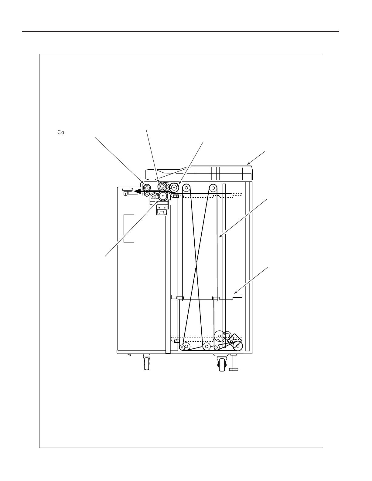
CENTER CROSS-SECTIONAL DRAWING
Feed roller
Conveyance roller
Paper feed roller
Top cover
Up/down wire
(the other side
wire as well)
Double feed
prevention roller
Up/down plate
2
Page 11

DRIVE SYSTEM DRAWING
Paper feed drive section
LT First paper feed SD
(SD100)
LT-401/LT-411
Feed roller
Paper feed roller
FRONT
Conveyance roller
LT paper feed motor
(M101)
LT First paper feed MC
(MC 102)
LT feed drive MC
(MC101)
FRONT
Double feed
prevention roller
Paper feed roller
Feed roller
3
Page 12

LT-401/LT-411
Stacked paper up/down wire drive section
LT-401
Up/down plate
FRONT
LT up/down motor
(M100)
Up/down shaft
4
Page 13

LT-411
LT-401/LT-411
Up/down plate
FRONT
LT up/down motor
(M100)
Up/down shaft
5
Page 14

LT-401/LT-411
PAPER FEED SECTION
Composition
MC101(LT feed MC)
M101
(LT paper
feed motor)
MC102(LT first paper feed MC)
SD100
(LT first paper feed SD)
Paper dust
removing brush
Conveyance
roller
PS106 (LT feed PS)
PS107 (LT preregistration PS)
Up/down wire
(the other side wire
as well)
M100
(LT up/down
motor)
Remaining paper
detection gear
Mechanisms
Mechanism Method
*1 Paper lifting Wire drive
Paper feed Paper feed roller
No paper detection Photo sensor (PS108)
+actuator
Paper size detection
*2 Remaining paper Remaining paper de-
detection tection gear+photo
Paper conveyance Roller transport
*1: Paper lifting
a. Up/down plate lifting drive operation
The up/down plate is lifted with the up/down wires.
When the top cover closes, M100 (LT up/down)
rotates and the up/down plate connected to the
up/down wires rises.
None
sensors
(PS102, PS103, PS104,
PS105)
Up/down plate
SW 100 (LT tray down drive switch)
b. Up/down plate down drive operation
The up/down plate automatically lowers by 120
mm when the top cover is opened.
Subsequently, it is lowered by 120 mm each time
SW100 (LT tray down drive switch) is pressed.
*2: Remaining paper detection
The LCT is equipped with a remaining paper
detection gear which rotates together with M100
(LT up/down) driving the up/down plate.
The remaining paper detection gear has an
actuator to turn ON/OFF PS102 (LT remaining
paper detection PS1), PS103 (LT remaining
paper detection PS2), PS104 (LT remaining
paper detection PS3), and PS105 (LT remaining
paper detection PS4).
6
Page 15

LT-401/LT-411
Each sensor is turned ON/OFF according to the
rotating position of the remaining paper detection gear and since this is linked with the up/down
position of the up/down plate, the remaining
paper quantity in the LCT can be determined by
monitoring the ON/OFF of each sensor. The
remaining paper quantity detected with the four
sensors is displayed on the main body display.
a. LT-401
M100 (LT up/down motor)
Actuator
PS102 (LT
remaining paper
detection PS1)
PS103 (LT
remaining
PS104 (LT
remaining
paper
detection
PS3)
Gear for M100
Remaining
paper detection
PS105 (LT
remaining paper
detection PS4)
gear
b. LT-411
PS102 (LT
remaining paper
detection PS1)
PS103 (LT
remaining
paper
detection
PS2)
PS104 (LT
remaining paper
detection PS3)
paper
detection
PS2)
First paper feed control
LT DB
HTR101
MAIN BODY
HTR101 CONT
AC(H)
24VDC
PGND
5VDC
SGND
LT TXD
LT RXD CLK
LT TXD LATCH
LT TXD CLK
LT ERR
LT RXD
LT ACK
LT REQ
(LT-411 only)M101 H/L
The first paper is fed by the paper feed roller and the
feed roller driver by M101(L T paper f eed) via MC101(L T
feed MC). The feed roller ass'y is lowered by SD100
(first paper-feed) to touch the paper when MC101 (LT
feed) turns ON and dr ive SD100 (LT first paper feed).
After touching and feeding the paper, the feed roller
ass'y is raised by SD100 (LT first paper f eed) to release
the feed roller ass'y from the paper. Then, the paper is
fed into the paper conveyance section by the paper
feed roller which is driven by M101 via MC102 (LT first
paper feed).
The related signals are: PS100 (LT top cover open/
close detection), PS106 (LT feed), PS107 (LT preregistration), and PS110 (LT jam access door open/
close detection).
5VDC
PS100
SGND
5VDC
PS106
SGND
PS107
5VDC
PS110
SGND
24VDC
MC101 DRIVE
24VDC
MC102 DRIVE
24VDC
SD100 DRIVE
24VDC
M101 CONT
M101 EM
PGND
PS100
PS106
PS107
PS110
MC101
MC102
SD100
MS101 MS102
M101
Actuator
Remaining paper
detection gear
Gear for M100
PS105 (LT
remaining paper
detection PS4)
1. Operation
a. First paper feed timing
Normally, this machine feeds paper at a speed
of 600 mm/s. When the longitudinal length of
paper is 300 mm or more, this machine cannot
complete paper ejection even if paper has
reached the image transfer section. The paper
feed speed of the image transfer section is 370
mm/s at this time. Theref ore, the L T-411 in which
paper with a longitudinal length of 300 mm or
more is set changes the paper feed speed from
7
Page 16

LT-401/LT-411
600 mm/s to 370 mm/s for the image transfer
section.
Paper with a longitudinal length of less than 300
mm/s is ejected before it reaches the image transfer section, so the paper feed speed is fixed at
600 mm/s.
The description given under “Paper with a longitudinal length of less than 300 mm is fed in the
following case:” also covers the operation of the
LT-401 that can handle only the paper with a
length of less than 300 mm.
(1) Start of first paper feed
• Paper with a longitudinal length of less than
300 mm is fed in the following case:
At predefined interval after the START button
is pressed(Paper feed speed does not
change.)
• Paper with a longitudinal length of 300 mm or
more is fed in the following case:
High-speed paper feed starts when the specified time lapses after the START button is
pressed. The high speed paper feed feed is
switched to the low speed paper feed after
PS44 (second paper feed) is turned ON and
loop is formed.
(2) Start of second and subsequent papers
• When PS106 (LT feed) is turned OFF by the
preceding paper, the paper feed speed is low
for the paper with a longitudinal length of 300
mm or more.This low speed paper feed is
switched to the high speed paper feed for the
next paper as soon as PS107(LT preregistration) is turned OFF.
(3) OFF timing
When the specified time lapses after PS106 is
turned OFF by the last paper
b. Interlock
The power supply line of M101 (LT paper feed)
is equipped with MS101 (LT inter l o ck MS1) and
MS102 (LT inter l o ck MS2). When the top cover
is opened, MS101 turns OFF, and when the jam
access door is opened MS102 turns OFF , thereb y
cutting off the power supply to M101.
Furthermore, the top cover is equipped with
PS100 (LT top cover open/close detection) and
the jam access door is equipped with PS110 (LT
jam access door open/close detection) and when
either of these doors is opened during paper feed,
the M101 drive signal is turned OFF to stop the
paper feed operation.
c. Internal heater
The LCT is equipped with HTR101 (LT inter nal
heater) to protect the paper from humidity.
HTR101 is directly controlled by the main body
ACDB (AC drive board) rather than by the LTDB
(LT drive board).
2. Signals
a. Input signals
(1) PS100 (PS100 to LTDB)
Top cover open/close detection signal
[L]: Cover opened
[H]: Cover closed
(2) PS106 (PS106 to LTDB)
Transport roller exit paper detection signal
[L]: Paper detected
[H]: Paper not detected
(3) PS107 (PS107 to LTDB)
Transport roller entrance (pre-registration
position) paper detection signal
[L]: Paper detected
[H]: Paper not detected
(4) PS110 (PS110 to LTDB)
Jam access door open/close detection signal
[L]: Door opened
[H]: Door closed
(5) M101 EM (M101 to LTDB)
M101 rotation error detection signal
[L]: M101 rotating
[H]: M101 not rotating
(6) LT TXD (MAIN BODY to LTDB)
Serial data to transmit main body PRCB operating status to LTDB
(7) LT TXD LATCH (MAIN BODY to LTDB)
LT TXD signal latch signal
(8) LT TXD CLK (MAIN BODY to LTDB)
LT TXD signal clock signal
(9) LT ERR (MAIN BODY to LTDB)
Signal to notify LTDB when there is error in the
main body
(10)LT ACK (MAIN BODY to LTDB)
Serial data transmission enable signal from LCT
to main body PRCB
8
Page 17

b. Output signal
(1) MC101 DRIVE (LTDB to MC101)
MC101 ON/OFF drive signal
[L]: MC101 ON
[H]: MC101 OFF
(2) MC102 DRIVE (LTDB to MC102)
MC102 ON/OFF drive signal
[L]: MC102 ON
[H]: MC102 OFF
(3) SD100 DRIVE (LTDB to SD100)
SD100 ON/OFF drive signal
[L]: SD100 ON
[H]: SD100 OFF
(4) M101 CONT (LTDB to M101)
M101 ON/OFF control signal
[L]: M101 ON
[H]: M101 OFF
(5) LT RXD (LTDB to MAIN BODY)
Serial data to transmit the L TDB operating status
to main body PRCB
(6) LT RXD CLK (LTDB to MAIN BODY)
LT RXD signal clock signal
(7) LT REQ (LTDB to MAIN BODY)
Serial data send request signal from LCT to main
body PRCB
(8) M101 H/L (LTDB to M101)
M101 speed control signal. (LT-411 only)
[L]: Low speed rotation
[H]: High speed rotation
LT-401/LT-411
9
Page 18

LT-401/LT-411
Up/down plate drive control
LT DB
MAIN BODY
24VDC
PGND
5VDC
SGND
LT TXD
LT RXD CLK
LT TXD LA TCH
LT TXD CLK
LT ERR
LT RXD
LT ACK
LT REQ
When the top cover opens or closes, M100 (LT up/
down motor) rotates forward or backward to move the
up/down plate up or down. The up/down plate descends
by 120 mm each time SW100 (LT tray down drive
switch) is pressed while the top cover is opened. The
related signals are PS100 (LT top cover open/close
detection), PS101 (L T lower limit detection), and PS109
(LT upper limit detection).
1. Operation
a. Up/down plate descend timing
(1) ON timing
When the top cover is opened and PS100 is
turned OFF, M100 rotates backward to lower the
up/down plate.
When SW100 (LT tray down drive switch) turns
ON by pressing, M100 rotates backward to move
the up/down plate down.
(2) OFF timing
M100 turns OFF at predefined interval after
PS100 turns OFF or SW100 tur ns ON. This in
turn lowers the up/down plate by 120 mm.
(3) Others
The up/down plate descends by 120 mm each
time SW100 is pressed until PS101 turns ON to
indicate the bottom limit of the up/down plate.
5VDC
PS100
SGND
5VDC
PS101
SGND
SW100
5VDC
PS109
SGND
M100 DRIVE
M100 DRIVE
PS100
PS101
SW100
PS109
M100
b. Up/down plate ascend timing
(1) ON timing
When the top cover is closed and PS100 is turned
ON, M100 rotates forward to raise the up/down
plate.
(2) OFF timing
When the up/down plate rises and PS109 (LT
upper limit detection) turns ON to indicate the
detection of the topmost paper, M100 turns OFF
and stops the up/down plate.
The up/down plate also stops when the top cov er
is opened and PS100 turns OFF.
2. Signals
a. Input signals
(1) PS101 (PS101 to LTDB)
Up/down plate lower limit detection signal
[L]: Up/down plate not at lower limit
[H]: Up/down plate at lower limit
(2) PS109 (PS109 to LTDB)
Up/down plate upper limit detection signal
[L]: Up/down plate not at upper limit
[H]: Up/down plate at upper limit
(3) SW100 (SW100 to LTDB)
SW100 ON/OFF detection signal
[L]: SW100 ON
[H]: SW100 OFF
b. Output signals
(1) M100 DRIVE1, 2 (LTDB to M100)
M100 drive signal
These signals switches the direction of the drive
current to control the rotation direction of M100.
10
Page 19

LT-401/LT-411
Remaining paper detection/No paper
detection control
LT DB
MAIN BODY
24VDC
PGND
5VDC
SGND
LT TXD
LT RXD CLK
LT TXD LA TCH
LT TXD CLK
LT ERR
LT RXD
LT ACK
LT REQ
The remaining paper quantity is detected by PS102
(LT remaining paper detection 1), PS103 (LT remaining paper detection 2), PS104 (LT remaining paper
detection 3), and PS105 (LT remaining paper detection 4) and no paper detection is made by PS108 (LT
no paper detection).
The signals detected by these sensors are controlled
by LTDB (LT drive board) and displayed on the main
body display.
1. Operation
a. Remaining paper detection control
The remaining paper quantity is determined from
the ON/OFF combination of sensors PS102,
PS103, PS104, and PS105 which detect the
rotational position of M100 that is driving the up/
down plate. Each sensor turns ON or OFF according to the position of the remaining paper
detection gear which is linked with the rotation of
M100.
The remaining paper quantity is detectable at
eight levels, but it is displayed on the main body
display as five levels.
5VDC
PS102
SGND
5VDC
PS103
SGND
5VDC
PS104
SGND
5VDC
PS105
SGND
5VDC
PS108
SGND
M100 DRIVE
M100 DRIVE
PS102
PS103
PS104
PS105
PS108
M100
<Remaining paper quantity and display>
Stacked
paper
PS102 PS103 PS104 PS105
quantity
0 to 700
701 to 1200
1201 to 1700
1701 to 2200
2201 to 2700
2701 to 3200
3201 to 3700
3701 or
OFF
ON
ON
ON
ON
OFF
OFF
OFF
OFF
OFF
ON
ON
ON
ON
OFF
OFF
OFF
OFF
OFF
ON
ON
ON
ON
OFF
Remaining
paper quantity
display
1 flashing
OFF
1 on
OFF
2 on
OFF
2 on
OFF
3 on
ON
3 on
ON
4 on
ON
4 on
ON
more
Caution:
The remaining paper quantity is indicated
on the control panel with four horizontal bars.
Stacked paper quantity differs depending on
the thickness of the paper.
b. No paper detection control
When there is no more paper inside the LCT,
PS108 turns ON and a message is displayed on
the main body display.
2. Signals
a. Input signals
(1) PS102 (PS102 to LTDB)
Remaining paper detection gear rotational
position detection signal
[L]: PS102 OFF
[H]: PS102 ON
(2) PS103 (PS103 to LTDB)
Remaining paper detection gear rotational
position detection signal
[L]: PS103 OFF
[H]: PS103 ON
(3) PS104 (PS104 to LTDB)
Remaining paper detection gear rotational
position detection signal
[L]: PS104 OFF
[H]: PS104 ON
(4) PS105 (PS105 to LTDB)
Remaining paper detection gear rotational
position detection signal
[L]: PS105 OFF
[H]: PS105 ON
(5) PS108 (PS108 to LTDB)
LCT no paper detection signal
[L]: No paper
[H]: Paper present
11
Page 20

LT-401/LT-411
PAPER FEED SECTION
Cleaning the Paper Dust Removing
Brush
Caution: If LT is connected to the main
unit, make sure that main unit
power plug is disconnected
from the power outlet.
a. Procedure
(1) Open the top cover.
(2) Remove the two screws to detach the paper feed
cover B.
Top
cover
Screws
Cleaning the PS106 (LT feed PS)/PS107
(LT pre-registration PS)
Caution: If LT is connected to the main
unit, make sure that main unit
power plug is disconnected
from the power outlet.
a. Procedure
(1) Looking into the paper ejection side of the LCT
from below, and clean sensors through the cavity
for PS106 and the cavity for PS107 using a
blower brush or the like.
Cavity for PS106
Cavity for PS107
Paper
exit
side
Paper feed cover B
(3) Insert a flat bladed screwdriver in the slots (in two
locations) for paper dust removing brush to release the locking lugs, then remove the paper
dust removing brush.
Paper dust removing
brush
Cavity
Locking lugs
(4) Clean the paper dust removing brush using a
blower brush or the like.
(5) Reinstall the above parts following the removal
steps in reverse.
Removing and Reinstalling the Paper
Feed Roller Unit
Caution: If LT is connected to the main
unit, make sure that main unit
power plug is disconnected
from the power outlet.
a. Procedure
(1) Open the top cover.
(2) Remove the spring from the paper feed roller unit.
Top cover
Spring
Remove
this.
Paper feed roller
unit
Paper feed roller unit
12
Page 21
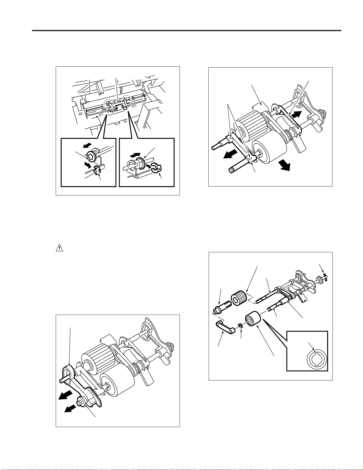
LT-401/LT-411
(3) After removing the two retaining rings, remove
the two bearings outward to remove the paper
feed roller unit.
Paper feed roller unit
Bearing
Retaining
ring
Bearing
Retaining
ring
(4) Reinstall the above parts following the removal
steps in reverse.
Replacing the Paper feed Roller Rubber/
Feed Roller Rubber
Caution: If LT is connected to the main
unit, make sure that main unit
power plug is disconnected
from the power outlet.
a. Procedure
(1) Remove the paper feed roller unit.
(2) Remove the bearing and paper feed reference
actuator.
(3) Remove the two retaining rings.
(4) Remove the bearing outward to detach the roller
section from the roller fitting.
Roller fitting
Retaining
ring
Bearing
Bearing
(5) Remove the bearing from the opposite side of the
coupling, then remove the paper feed roller from
the shaft.
(6) Remove the retaining ring to pull the feed roller
from the shaft.
(7) Remove the rubber from each roller.
Paper feed roller rubber
Paper feed
roller
Shaft
Coupling
Paper feed reference actuator
Bearing
13
Bearing
Retaining
ring
Shaft
Feed roller
rubber
Feed roller
Paint
mark
Page 22

LT-401/LT-411
(8) Reinstall the above parts following the removal
steps in reverse.
Caution 1: Make sure rollers and rubber por-
tions are oriented properly when
reinstalling them.
Caution 2: Make sure the one-way clutch
direction is correct.
Caution 3: Check whether grease or the like
is present on each roller.
Replacing the Double Feed Prevention
Roller Rubber
Caution: If LT is connected to the main
unit, make sure that main unit
power plug is disconnected
from the power outlet.
a. Procedure
Caution: With the power held on, press the
SW100 (L T tray down s witch) to mov e
the up/down plate down to the bottom
in advance.
(1) Remove the paper feed roller unit.
(2) Remove the two screws to detach the double
feed prevention roller unit cover.
(3) Remove the two screws to detach the double
feed prevention roller unit.
Caution: When reinstalling the double feed
prevention roller unit, tighten the
screws on the rear side first.
Double feed prevention roller unit
Screws
(4) Remove the two retaining rings, fit the shaft into
the D-cut in the fitting, and remove the double
feed prevention roller together with the shaft.
Double feed
prevention roller
Double feed
prevention roller
unit cover
Screws
Double feed
prevention roller
D-cut
Retaining ring
14
Page 23

LT-401/LT-411
(5) Remove the double feed prevention roller rubber
from the double feed prevention roller.
Paint mark
Double feed
prevention roller
Shaft
Double feed
prevention roller
rubber
(6) Reinstall the double feed prevention roller in the
reverse order of the removal procedure.
Caution 1: Make sure the double f eed pre ven-
tion roller rubber is oriented
properly when reinstalling it.
Caution 2: Check whether scratch or like is
visible on the pet cock for the
drive gear.
Caution 3: Check whether grease or the like
is present on double feed roller.
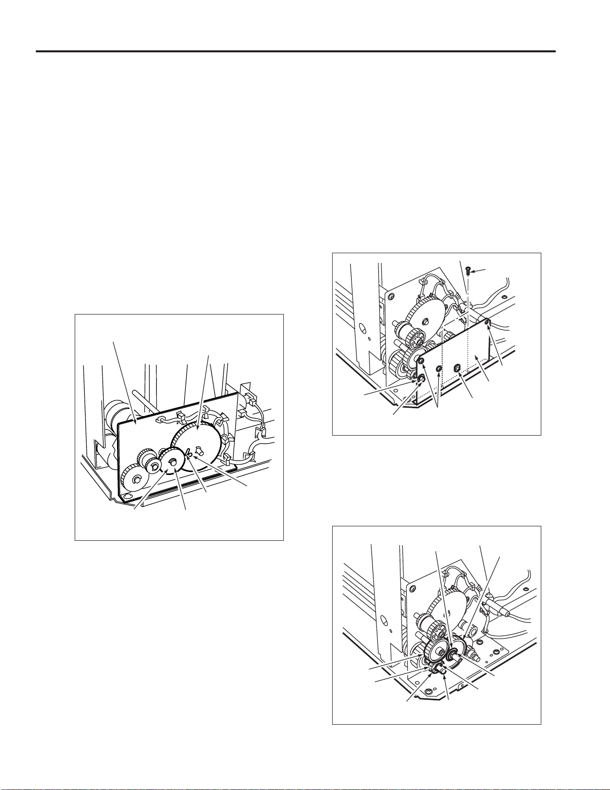
Replacing the MC101 (LT feed MC)
MC102 (LT first paper feed MC)
a. Procedure
(1) Open the top cover.
(2) Remove the spring from the paper feed roller unit.
(3) Remove the two screws to detach the top cover.
Top cover
Screws
(4) Remove the two screws to detach the clutch
replacement cover.
Clutch replacement
cover
15
Screws
Page 24

LT-401/LT-411
(5) Disconnect two relay connectors (CN765, CN766)
of the clutches.
(6) Remove the retaining ring to detach each clutch.
MC101 (LT Paper feed MC)
Retaining
ring
Relay
connector
(CN766)
MC102 (LT first
paper feed MC)
Retaining
ring
Relay connector
(CN765)
(7) Reinstall the above parts following the removal
steps in reverse.
Caution: When installing each MC, make
sure that the stopper of each clutc h
is on the predefined position.
(3) Remove the four screws to detach the right side
cover.
Screws
Right side
cover
Screws
(4) After opening the jam access door, remove the
four screws to detach the front cover.
Caution: Remove the four screws and then
remove the front cover with the
jam access door closed.
Replacing the LT-401 Up/Down Wires
a. Procedure
Caution: With the power held on, press the
SW100 (L T tray down s witch) to mov e
the up/down plate down to the bottom
in advance.
(1) Open the top cover.
(2) Remove the clutch replacement cover.
Jam access door
Screws
Screws
Right side cover
16
Page 25

LT-401/LT-411
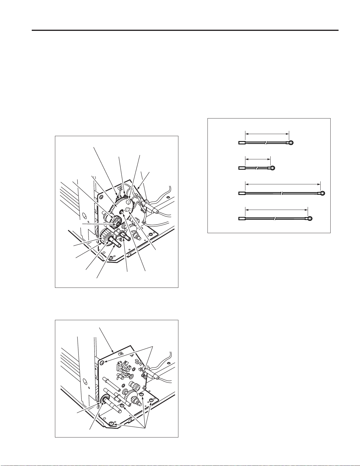
(5) Remove the five screws to detach the rear cover.
Screw
Rear cover
Screws
Screws
(6) Remove the five relay connectors (CN749,
CN780, CN781, CN782, CN783) to disconnect
the wiring harness from the up/down motor mount-
ing plate.
(7) Remove the E-ring to detach the up/down gear.
(8) Pull the pin from the shaft.
(9) Remove the E-ring to detach the bearing.
(10)Remove the three screws to detach the up/down
motor assembly.
(11)Replace the up/down wire following the instruc-
tions in “Removing Up/Down Wires” and “Installing Up/Down Wires.”
Caution: Four up/down wires with different
length, two at the front and two at the
back, are used. Wires with the same
length can be used either at the front
or back if they are used in the same
location.
1323.6mm
Wire A
1250.3mm
Wire B
769.3mm
Wire C
661mm
Wire D
Up/down
motor
assembly
Shaft
Relay connector
(CN749)
Screw
Pin
Screw
Bearing
Relay
connector
(CN780)
E-ring
Relay
connector
(CN781)
Relay
connector
(CN782)
Relay
connector
(CN783)
Screw
Up/down
gear
E-ring
17
Page 26

LT-401/LT-411
<Removing the Up/Down Wires>
Up/down plate
Wire B
14.Release the metal
ball to remove wire
A.
7. Release the metal
ball to remove wire
C.
9. Release the metal
ball to remove wire
D.
12.Release the metal
ball to remove wire
B.
Wire A
Wire B
Wire A
2. Release the metal
ball to remove wire
C.
18.Release the metal
ball to remove wire
A.
4. Release the metal
ball to remove wire
D.
16.Release the metal
ball to remove wire
B.
Wire D
Wire C
1. Remove the E-ring.
3. Remove the pulley.
5. Remove the pulley.
Wire C
Wire D
6. Remove the E-ring.
8. Remove the pulley.
10.Remove the pulley.
11.Remove the E-ring,
then remove the
pulley to release
wire B.
FRONT
13.Remove the pulley to
release wire A.
Up/down
shaft
15.Remove the Ering, then remove
the pulley to
release wire B.
17.Remove the pulley
to release wire A.
18
Page 27

<Installing the Up/Down Wires>
LT-401/LT-411
Wire A
Wire B
7. Insert wire A in the
pulleys, then attach a
metal ball.
15.Insert wire C in the
pulleys, then attach a
metal ball.
12.Insert wire D in the
pulleys, then attach a
metal ball.
10.Insert wire B in the
pulleys, then attach a
metal ball.
Wire C
Wire D
13.Insert wire C in the up/
down shaft, attach a
pulley, and secure the
pulley with an E-ring.
14.Wind wire C around
the pulley by 6 turns in
such a manner that the
wire can be pulled
from over the pulley.
Wire B
Wire A
FRONT
Up/down plate
Up/down
shaft
1. Insert wire A in
the up/down
6.
shaft, attach
pulleys, then
pull the wire
from under the
pulleys.
20.Insert wire B in the pulleys,
then attach a metal ball.
2. Insert wire A in the pulleys,
then attach a metal ball.
17.Insert wire D in the pulleys,
then attach a metal ball.
5. Insert wire B in the pulleys,
then attach a metal ball.
Wire D
Wire C
18.Insert wire C in the up/
down shaft, attach a
pulley, and secure the
pulley with an E-ring.
19.Wind wire C around
the pulley by 6 turns
in such a manner that
the wire can be pulled
from over the pulley.
6 turns
6 turns
11.Insert wire D in the up/
down shaft, attach a
pulley, and wind wire
D around the pulley by
six turns in such a
manner that the wire
can be pulled from
over the pulley.
6 turns
3. Insert wire B in the up/
down shaft, attach a
8.
pulley, and secure the
pulley with E-rings.
4. Pull wire B from under the
pulleys.
9.
19
16.Insert wire D in the up/
down shaft, attach a
pulley, and wind wire
D around the pulley by
six turns in such a
manner that the wire
can be pulled from
over the pulley.
6 turns
Page 28
LT-401/LT-411
(12)After installing the up/down wires, make sure the
up/down wires are passed in the grooves in the
pulleys properly and wires do not run on the sides
of the pulleys. Also make sure the up/down plate
can be moved up and down smoothly by hand.
Caution: If the up/down plate does not move
up and down smoothly, reinstall the
up/down wires.
(13)Install the up/down wire drive motor assembly,
up/down gear, and relay connectors, following
the removal steps in reverse.
(14)Remove the E-ring to detach the idle gear.
(15)Rotate the remaining paper detection gear until
the round hole in this gear is aligned with the
oblong hole in the up/down motor mounting plate.
Caution: Align when the up/down plate is in
lowest position.
Up/down motor
mounting plate
Remaining paper
detection gear
Replacing the LT-411 Up/Down Wires
a. Procedure
Caution: With the power held on, press the
SW100 (L T tray down s witch) to mov e
the up/down plate down to the bottom
in advance.
(1) Remove the clutch replacement cover, side cover
(right), front cover, and rear cover following the
steps (1) to (5) in [7] Replacing the LT-401 Up/
Down Wires.
(2) Remove the E-ring.
(3) Remove the five screws to detach the gear cover.
(4) Remove the two bearings.
Screw
Round
Oblong
hole
E-ringIdle gear
hole
(16)Install the idle gear.
(17)Attach the covers following the removal steps in
reverse.
Caution: After replacing the up/down wires,
correct horizontal and centering of the
up/down plate. (Refer to “ADJUSTMENT SECTION.”)
Screw
Gear cover
E-ring
Bearing
Screws
Bearing
(5) Remove the gear A.
(6) Remove the E-ring to remove gear B.
(7) Remove the detent pin for gear B from the up/
down pulley shaft.
(8) Remove the E-ring and bearing to remove gear C.
Bearing
Gear C
20
Gear A
Pin
Gear B
E-ring
E-ring
Up/down pulley shaft
Page 29
LT-401/LT-411
(9) Remove the bearing behind gear C.
(10)Remove the E-ring to remove the up/down gear.
(11)Remove the detent pin for up/down gear from the
up/down pulley shaft.
(12)Remove the E-ring to remove gear D.
(13) Remove the E-ring to remove the remaining
paper detection gear.
(14)Remove the four relay connectors (CN780,
CN781, CN782, and CN783) to disconnect the
wiring harness from the up/down motor mounting
plate.
Relay connector
(CN780)
Remaining paper
detection gear
Gear D
Relay
connector
(CN781)
Relay connector
(CN782)
Up/down motor
mounting plate
(17) Replace the up/down wire following the instruc-
tions in “Removing the Up/Down Wires” and
“Installing Up/Down Wires.”
Caution: Four up/down wires with different
length, two at the front and two at the
back, are used. Wires with the same
length can be used either at the front
or back if they are used in the same
location.
1057.3mm
Wire A
692.1mm
Wire B
1321.7mm
Wire C
1303.1mm
E-ring
Pin
Relay
Up/down
gear
E-ring
Up/down pulley shaft
Bearing
connector
(CN783)
E-ring
(15)Remove the E-ring to remove the bearing.
(16)Remove the six screws to remove the up/down
motor mounting plate.
Up/down motor mounting plate
Screws
Wire D
Bearing
E-ring
Screws
21
Page 30

LT-401/LT-411
<Removing the Up/Down Wires>
Wire C
Wire D
14.Release the metal
ball to remove wire
D.
7. Release the metal
ball to remove wire
A.
9. Release the metal
ball to remove wire
B.
12.Release the metal
ball to remove wire
C.
Wire C
Wire D
Up/down plate
2. Release the metal
ball to remove wire
A.
18.Release the metal
ball to remove wire
D.
4. Release the metal
ball to remove wire
B.
16.Release the metal
ball to remove wire
C.
Wire B
Wire A
1. Remove the E-ring.
3. Remove the pulley.
Wire A
6. Remove the E-ring.
8. Remove the pulley.
10.Remove the pulley.
Wire B
Front
11.Remove the E-ring,
then remove the
pulley to release
wire C.
Up/down shaft
13.Remove the pulley to
release wire D.
5. Remove the pulley.
15.Remove the E-ring,
then remove the
pulley to release
wire C.
17.Remove the pulley
to release wire D.
22
Page 31

<Installing the Up/Down Wires>
LT-401/LT-411
Wire C
Wire D
Wire C
Wire D
7. Insert wire D in the
pulleys, then attach a
metal ball.
15.Insert wire A in the
pulleys, then attach a
metal ball.
12.Insert wire B in the
pulleys, then attach a
metal ball.
10.Insert wire C in the
pulleys, then attach a
metal ball.
Wire A
Wire B
13.Insert wire A in the up/down
shaft, attach a pulley, and
secure the pulley with an E-ring.
14.Wind wire A around the pulley
by 6 turns in such a manner
that the wire can be pulled
from over the pulley.
6 turns
11.Insert wire B in the up/down shaft,
attach a pulley, and wind wire B
around the pulley by six turns in
such a manner that the wire can
be pulled from over the pulley.
Up/down plate
Front
1. Insert wire D in the
up/down shaft, attach
6.
pulleys, then pull wire
D from under the
pulleys.
3. Insert wire C in the up/down
shaft, attach a pulley, and
8.
secure the pulley with E-rings.
4. Pull wire C from under the
pulleys.
9.
Up/down
shaft
20.Insert wire A in the
pulleys, then attach a
metal ball.
2. Insert wire D in the
pulleys, then attach a
metal ball.
17.Insert wire B in the
pulleys, then attach a
metal ball.
5. Insert wire C in the
pulleys, then attach a
metal ball.
Wire B
Wire A
18.Insert wire A in the up/
down shaft, attach a
pulley, and secure the
pulley with an E-ring.
19.Wind wire A around the
pulley by 6 turns in such
a manner that the wire
can be pulled from over
the pulley.
6 turns
16.Insert wire B in the up/
down shaft, attach a
pulley, and wind wire B
around the pulley by six
turns in such a manner
that the wire can be
pulled from over the
pulley.
6 turns
6 turns
23
Page 32

LT-401/LT-411
(18)After installing the up/down wires, check whether
they are engaged with the pulleys properly and
whether they do not ride over the pulleys. Next,
move the up/down plate manually to check
whether it moves up and down smoothly.
Caution: If the up/down plate does not move
smoothly, remo ve the up/down wires
and install them again.
(19)Install the up/down motor mounting plate, relay
connectors, remaining paper detection gear, gear
D, and up/down gear following the removal steps
in reverse.
(20)Rotate the remaining paper detection gear until
the round hole in this gear is aligned with the
oblong hole in the up/down motor mounting plate.
Remaining
paper detection
gear
Oblong hole
Up/down motor mounting plate
Round hole
Caution: Align them when the up/down plate is
at the bottom.
(21)Install gear C.
(22)Attach the other gears, gear cover, and external
covers following the removal steps in reverse.
Caution: After replacing the up/down wires,
correct horizontal and centering of the
up/down plate. (Refer to “ADJUST-
MENT SECTION.”)
24
Page 33

LT-401/LT-411
LT-401/LT-411 ELECTRICAL PARTS LAYOUT DRAWING
SW100
LT tray down drive switch
PS107
LT pre-registration PS
MS102
LT interlock MS2
PS100
LT top cover open/
close detection PS
MC101
LT feed drive MC
M100
LT up/down motor
PS102
LT remaining
paper detection PS1
PS103
LT remaining
paper detection PS2
PS104
LT remaining
paper detection PS3
PS108
LT No paper detection PS
PS105
LT remaining paper detection PS4
MS101
LT inter lock MS1
PS110
LT jam access door
open/close detection PS
SD100
LT 1st paper feed SD
PS109
LT upper limit detection PS
PS106
LT feed PS
MC102
LT 1st paper feed MC
M101
LT paper feed motor
LTDB
LT drive board
HTR101
LT internal heater
PS101
LT lower limit detection PS
25
Page 34

LT-401/LT-411
LT-401/LT-411 CONNECTOR LAYOUT DRAWING
744 (W: 3pin)
742 (W: 3pin)
741 (W: 3pin)
766 (W: 2pin)
784 (W: 2pin)
747 (W: 3pin)
746 (W: 3pin)
765 (W: 2pin)
774 (W: 2pin)
762 (W: 3pin)
749 (W: 3pin)
780 (B: 3pin)
781 (W: 3pin)
783 (W: 3pin)
782 (B: 3pin)
Caution: Must use fuses specified by
Konica when replacing F1. If
fuse is not specified by Konica,
the safety feature may not work,
resulting in burn damag e to the
board or personal injury.
745 (W: 3pin)
761 (W: 2pin)
767 (W: 2pin)
773 (W: 3pin)
740 (W: 3pin)
773 (W: 2pin)
771 (W: 2pin)
751 (W: 6pin)
750 (W: 10pin)
720 (W: 5pin)
F1
723 (W: 8pin)
721
(W: 8pin)
722
(GY: 20pin)
Parts specified by Konica
Part P art number
F1 963003200
700 (W: 4pin) 710 (GY: 18pin)
LTDB
26
Page 35

LT-401 TIMING CHART (8.5X11, TWO SHEETS)
(sec)
LT-401/LT-411
200msmin380ms
Loop amount Loop amount
300ms
012
Start button ON
Time (sec)
Item
Symbol
LT paper feed motor
M101
LT feed drive clutch
MC101
LT first paper feed
solenoid
SD100
LT first paper feed
clutch
MC102
27
LT pre-registration
sensor
PS107
LT feed sensor
PS106
Page 36

LT-401/LT-411
LT-411 TIMING CHART (11X17, TWO SHEETS)
(sec)(sec)
Timer
(Second paper feed loop)
Timer Timer
min380ms min380ms
012 34
H
Time
300ms
L
Loop amount
Loop amount
Timer
(Second paper feed loop)
Start button ON
Item
Symbol
LT paper feed
motor
M101
LT feed drive clutch
MC101
LT first paper feed
SD100
solenoid
LT first paper feed
MC102
Registration clutch
clutch
MC1
28
LT pre-registration
sensor
PS107
LT feed sensor
PS106
Registration
sensor
PS44
Page 37

LT-401/LT-411 OVERALL WIRING DIAGRAM
LT FEED DRIVE
CLUTCH
MC101
766-1-2
766-2-1
723-3
723-4
24VDC
H L
MC101 DRIVE
5VDC
PS100
SGND
722-A1
722-A4
722-A7
746-1
746-2
746-3
PS100
LT
TOP COVER
OPEN/CLOSE
DETECTION
SENSOR
LT FIRST PAPER FEED
LT FIRST PAPER FEED
[How to see the diagram]
1.The signals shown reflect levels present
under normal idling conditions with
the main switch turned ON.
2.Wiring symbols in the figure are as follows.
(1) [Symbol]
50-1
V
V
CLUTCH
SOLENOID
LT UP/DOWN
DRIVE MOTOR
LT
INTERLOCK
MS1
LT
INTERLOCK
MS2
LT PAPER FEED
MOTOR
LT INTERNAL
HEATER
MC102
SD100
M100
MS101
MS102
M101
HTR101
762-1
762-2
762-3
762-4
762-5
765-1-2
765-2-1
767-1-2
766-2-1
749-2
749-1
761-1
761-2
773-3
773-4
LT-411 only
723-5
723-6
723-7
723-8
723-1
723-2
720-1
720-2
720-3
720-4
720-5 M101 H/L
24VDC
MC102 DRIVE
H
24VDC
SD100 DRIVE
H
M100 DRIVE 1
M100 DRIVE 2
24VDC
M101 CONT
H
M101 EM
H
PGND
722-A2
5VDC
PS101
SGND
722--A6
H
722-A8
745-1
745-2
745-3
PS101
LT
LOWER LIMIT
DETECTION
SENSOR
LT
5VDC
PS102
SGND
722-A3
722-A5
722-A9
780-1
780-2
780-3
PS102
REMAINING
PAPER
DETECTION
SENSOR
1
LT
5VDC
PS103
SGND
722B8
722-B5
722-B2
781-1
781-2
781-3
PS103
REMAINING
PAPER
DETECTION
SENSOR
2
LT
5VDC
PS104
SGND
722-B9
722-B6
722-B3
782-1
782-2
782-3
PS104
REMAINING
PAPER
DETECTION
SENSOR
3
LT
5VDC
PS105
SGND
722-B10
722-B7
722-B4
783-1
783-2
783-3
PS105
REMAINING
PAPER
DETECTION
SENSOR
4
1
5VDC
PS106
SGND
721-1
H
721-2
721-3
773-5
773-6
773-12
740-3
740-2
740-1
PS106
LT
FEED
SENSOR
Crimp
Connector
Faston
Wire(Violet)
(2) [Color code]
BN - Brown B - Blue
R - Red V - Violet
O - Orange GY - Gray
Y - Yellow W - White
GN - Green BK - Black
LB - Light blue P - Pink
Example: Y/GN represents
green yellow striped pattern.
(3) RC is the flat cable.
(4) Signal flow
The solid black circle ( ) among
the connector symbols ( )
indicates the direction of signal flow.
Example)
5VDC
PS1
SGND
Direction of
signal flow
PS1
CB
HTR101 CONT
LT TXD LATCH
MAIN BODY
AC(H)
24VDC
PGND
5VDC
SGND
LT TXD
LT TXD CLK
LT ERR
LT ACK
750-2-9
750-4-7
750-1-10
P
750-6-5
P
850-5-6
750-3-8
P
750-7-4
P
750-8-3
750-9-2
P
750-10-1
751-6
751-5
751-1
751-4
751-2
751-3
700-1
700-2
700-3
700-4
710-A1
710-A2
710-A3
710-A5
710-A7
710-A9
710-B2
710-B4
710-B6
710-B8
5VDC
SGND
LT RXD CLK
P
LT RXD
P
LT REQ
P
LT DB
PS107
PS108
PS109
PS110
SW100
H
721-3
721-4
L
721-5
L
721-6
L
773-7
773-8
773-9
773-10
741-3
741-2
741-1
742-1
742-2
742-3
744-1
744-2
744-3
747-1
747-2
747-3
PS107
PS108
PS109
PS110
LT
PRE-REGISTRATION
SENSOR
LT
NO PAPER
DETECTION
SENSOR
LT
UPPER LIMIT
DETECTION
SENSOR
LT JAM
ACCESS DOOR
OPEN/CLOSE
DETECTION
SENSOR
SW100
721-7
H
773-11
748-1
748-2
LT TRAY
DOWN DRIVE
SWITCH
29
Page 38

This page left blank intentionally.
30
Page 39

PARTS CATALOG
Model
LT-401
JANUARY 2000
KONICA BUSINESS TECHNOLOGIES, INC.
Page 40

Blank page.
Page 41

How to use this catalog
This parts catalog includes illustrations and part numbers for all replacement parts and assemblies used in this model.
Model-specific parts are identified in the illustrations with reference
numbers. Use the reference number to locate the corresponding part
number on the facing page.
Common hardware items, such as screws, nuts, washers, and pins,
are identified in the illustrations with reference letters. Use the reference
letter to locate the corresponding part number on the hardware listing in
the lower right hand corner of the facing page.
If you know a part number, but don’t know where the part is used, use
the numerical index to determine the page number and reference number for that part. Because some common parts are used in several
places, there may be more than one entry. Refer to the illustrations to
see where the part may be used.
If you know a part’s description, but don’t know where to look to find
the part number, use the alphabetical index to determine likely page and
reference numbers. Then look at the illustrations to determine that you
have identified the correct part. Locate the part number using the listing
on the opposite page.
Retail pricing that appears with the numerical index, while valid when
this catalog was printed, is subject to change without notice. The prices
are only suggested prices and are provided only for reference. Dealers
may determine their own selling prices. For up-to-date pricing, refer to
current Konica price lists or contact the Konica Parts Distribution Center.
How to order parts
Use standard Konica parts ordering procedures to obtain these parts.
For ordering options, contact Konica’s Parts Distribution Center.
When ordering parts, be sure to specify part numbers exactly as listed in
this catalog.
NOTE: Electrical parts may include previously used components.
Model LT-401 Konica Business Technologies, Inc. Page iii
1st Edition January, 2000
Page 42

This page left blank intentionally.
Page iv Konica Business Technologies, Inc. Model LT-401
January, 2000 1st Edition
Page 43

How to use this catalog . . . . . . . . . . . . . . . . . . . . . . . . . iii
Contents . . . . . . . . . . . . . . . . . . . . . . . . . . . . 1
LT-401 . . . . . . . . . . . . . . . . . . . . . . . . . . . . 2
Wiring . . . . . . . . . . . . . . . . . . . . . . . . . . . . 20
Alphabetical index . . . . . . . . . . . . . . . . . . . . . . . . . . . 23
Numerical index, Retail price list . . . . . . . . . . . . . . . . . . . . 25
Contents
Model LT-401 Konica Business Technologies, Inc. Page 1
1st Edition January, 2000
Page 44

LT-401
Page 2 Konica Business Technologies., Inc. Model LT-401
January, 2000 1st Edition
Page 45
REF. PART NUMBER DESCRIPTION
NO.
1 13GG10050 Board connecting stay/left
2 13GG10190 Driving protect cover
3 13GG10110 Main positioning plate
4 13GG10120 Sensor fixed plate
5 08AA85510 Photosensor
6 13GG-1070 Door sensor plate assembly
7 12QR86010 Inter lock switch
8 25AA85010 Switch/1
9 13GG90010 LCT signal wiring/front
10 13GG-1090 Jam door hinge/lower assembly
11 12AR45611 Actuator
12 13GG-9011 LCT driving board assembly
13 25AA83060 Paper fed heater
14 55VA42260 Heater cover
15 13GG10040 Board connecting stay/right
16 12AR10361 Magnet pressure plate
17 13GG90041 LCT control wiring
18 13GG10140 Sensor support plate/lower
19 12UM10090 LCT setting roller/left
20 12TR10110 LCT support part/left
21 13GG10150 Bottom plate support part
22 963003200 Fuse
HARDWARE
REF.
LTR.
a 00Z193061
b 00Z194061
c 00Z511001
d 00Z925106
e 00Z182101
f 00Z670206
g 00Z193041
PART
NUMBER
Model LT-401 Konica Business Technologies., Inc. Page 3
1st Edition January, 2000
Page 46

LT-401
Page 4 Konica Business Technologies., Inc. Model LT-401
January, 2000 1st Edition
Page 47

REF. PART NUMBER DESCRIPTION
NO.
1 13GG12010 Paper supply cover
2 12UM12100 Stopper part
3 13GG12110 Open-close hinge
4 25SA50530 Spring mount plate
5 050011160 Magnet catch
6 12AJ12110 Hinge plate/A
7 13GG12050 Jam open-close door
8 13GG12020 Front cover
9 13GG12060 Paper feed auxiliary cover/front
10 13GG12090 Clutch changeable cover
11 12UM40220 Lift-up spring
12 13GG12130 Paper guide knob
13 13GG12040 Rear cover
14 13GG12031 Side cover/right
15 12AJ12240 Mount cover/A
16 12AJ12251 Mount cover/B
17 12AJ12261 Open-close knob
18 12AJ12270 Open-close spring
19 13GG97010 Paper supply label
20 13GG97060 Paper feed indication label/4
HARDWARE
REF.
LTR.
a 00Z670306
b 00Z194061
c 00Z114061
d 00Z144062
e 00Z254081
f 00Z144082
g 00Z253061
PART
NUMBER
Model LT-401 Konica Business Technologies., Inc. Page 5
1st Edition January, 2000
Page 48

LT-401
Page 6 Konica Business Technologies., Inc. Model LT-401
January, 2000 1st Edition
Page 49

REF. PART NUMBER DESCRIPTION
NO.
1 13GG-1640 Fanning drive shaft
2 540076050 Driving shaft holder
3 55VA42060 Shaft support plate
4 55VA77680 Resist driving gear (Z=14)
5 304078040 Pin
6 13GG80010 LCT driving motor
7 55VA79070 Paper feed driving gear/B (Z=22/30)
8 55VA79080 Paper feed driving gear/C (Z=22)
9 13GG16050 Paper feed input shaft/1
10 12AR45611 Actuator
11 55VA79010 Paper feed reversal gear/A (Z=60)
12 55VA77770 Resist idler gear (Z=42/21)
13 13GG-1660 Paper feed driving plate assembly
14 25AA75090 Paper feed shaft holder
15 08AA85510 Photosensor
16 13GG10120 Sensor fixed plate
17 12QR86010 Interlock switch
18 13GG90030 LCT driving wiring
HARDWARE
REF.
LTR.
a 00Z670606
b 00Z670206
c 00Z194061
d 00Z670406
e 00Z182101
f 00Z193061
PART
NUMBER
Model LT-401 Konica Business Technologies., Inc. Page 7
1st Edition January, 2000
Page 50

LT-401
Page 8 Konica Business Technologies., Inc. Model LT-401
January, 2000 1st Edition
Page 51

REF. PART NUMBER DESCRIPTION
NO.
1 396040681 Snap ring
2 55VA41411 Entrance guide sheet
3 55VA-4830 Feeding roller assembly/B
4 13GG40060 Entrance guide plate
5 50BA40220 Reversal roller
6 55VA79140 Paper feed reversal gear/D (Z=19)
7 55FA58190 Toque limiter
8 55VA79030 Paper feed reversal gear/C (Z=14)
9 55VA79050 Idler gear/B (Z=24)
10 55VA42250 Paper feed driving cover/2
11 25AA40120 Spacer
12 55VA40310 Reversal spring/B
13 008478610 Bearing
14 55VA40190 Paper feed holder plate/lower
15 13GG-4240 Toque drive shaft assembly
16 098030300 Pin
HARDWARE
REF.
LTR.
a 00Z670606
b 00Z193061
c 00Z194061
d 00Z670406
e 00Z193041
PART
NUMBER
Model LT-401 Konica Business Technologies., Inc. Page 9
1st Edition January, 2000
Page 52

LT-401
Page 10 Konica Business Technologies., Inc. Model LT-401
January, 2000 1st Edition
Page 53

REF. PART NUMBER DESCRIPTION
NO.
1 55VA-4550 Paper dust scraper
2 55VA43360 Lock shaft holder
3 25AA40742 Connecting part/A
4 13GG-1241 Feeding cover assembly
6 13GG40041 Exit guide plate/lower
7 048645260 Stopper rubber
8 25AA48900 Open-close lever
9 25AA47700 Spring guide part
10 13GG40150 Paper feed pressure spring/front
11 13GG40140 Paper feed pressure spring/rear
12 13GG40080 Entrance guide plate/rear
13 13GG40010 Paper feed guide plate/upper
14 13GG40200 Sensor mount plate/A
15 08AA85510 Photosensor
16 13GG-1650 Paper feed driving shaft/A
17 090075530 Bushing
18 13GG90020 LCT signal wiring/upper
19 25AA85510 Photosensor
20 13GG40050 Paper conveyance roller
21 55VA75540 Paper feed shaft holder/B
22 55VA82010 Paper feed clutch
23 55VA42120 Shaft stopper
HARDWARE
REF.
LTR.
a 00Z670606
b 00Z183101
c 00Z163061
d 00Z193061
e 00Z193251
f 00Z194061
g 00Z183062
PART
NUMBER
Model LT-401 Konica Business Technologies., Inc. Page 11
1st Edition January, 2000
Page 54

LT-401
Page 12 Konica Business Technologies., Inc. Model LT-401
January, 2000 1st Edition
Page 55

REF. PART NUMBER DESCRIPTION
NO.
1 55VA41220 Paper feed standard actuator
2 396040681 Snap ring
3 55VA40260 Paper feeding shaft holder
4 13GG40180 Paper feed holder plate
5 13GG-4230 Feeding shaft
6 396078020 Pin
7 55VA-4830 Feeding roller assembly/B
8 13GG40130 Lever spring
9 55VA40150 Double feed feeding roller
10 197545110 Roller collar
11 25SA77561 Paper driving belt
12 059076510 Pulley/1
13 55VA40230 Paper feed lift-up lever
14 55VA40990 Lever auxiliary plate
15 55VA40130 Paper feeding roller/A
16 55VA-4840 Feeding roller assembly/A
17 131075510 Bearing/A
18 13GG40070 Entrance guide plate/front
19 55VA-4600 Pick-up solenoid
20 466076020 Paper feeding shaft holder
21 55VA42110 Solenoid stopper sheet
22 25AA40870 Switch lever/1
23 55VA42220 Positioning screw
24 25AA40742 Connecting part/A
25 55VA40440 Pressure plate/B
26 13GG40160 Pressure plate/L
HARDWARE
REF.
LTR.
a 00Z670306
b 00Z670406
c 00Z183041
d 00Z163061
e 00Z193061
PART
NUMBER
Model LT-401 Konica Business Technologies., Inc. Page 13
1st Edition January, 2000
Page 56

LT-401
Page 14 Konica Business Technologies., Inc. Model LT-401
January, 2000 1st Edition
Page 57

REF. PART NUMBER DESCRIPTION
NO.
1 12AJ45850 Stopper rubber
2 13GG42010 Paper stopper plate
3 25AA75530 Slide shaft holder
4 55VA40170 Conveyance driven roller
5 13GG-4100 Rear guide arm
6 55VA46490 Resist pressure spring
7 13GG42070 Paper positioning plate
8 25AA97320 Paper guide seal
9 13GG42041 Paper supply side plate
10 13GG42080 Side fixed plate
11 197510290 Shoulder screw
12 25BA47230 Rack plate (front)
13 25BA77301 Cassette pinion(Z=14)
HARDWARE
REF.
LTR.
a 00Z670406
b 00Z670306
c 00Z194061
d 00Z193061
e 00Z144062
f 00Z193081
g 00Z164061
PART
NUMBER
Model LT-401 Konica Business Technologies., Inc. Page 15
1st Edition January, 2000
Page 58

LT-401
Page 16 Konica Business Technologies., Inc. Model LT-401
January, 2000 1st Edition
Page 59

REF. PART NUMBER DESCRIPTION
NO.
1 55VA40930 Double feed preventive plate
2 13GG42020 Paper up-down plate
3 067642850 Spacer plate
4 13GG42140 Board positioning block
5 13GG42060 Up-down stay
6 25AA-4760 Wire fixed plate/A assembly
7 25AA-4780 Wire fixed plate/B assembly
8 25AA42800 Up-down spring
9 55VA44140 Sensor detecting plate
10 13GG-4190 Tension plate assembly/front
11 25AA41180 Wire holder/A
12 25AA41120 Driven pulley
13 13GG15120 Driving up-down wire/A
14 13GG15130 Driving up-down wire/B
15 13GG15140 Driving up-down wire/C
16 13GG-4200 Tension plate assembly/rear
17 25AA-4730 Wire mount plate assembly
18 25AA42570 Wire pulley
19 13GG15150 Driving up-down wire/D
HARDWARE
REF.
LTR.
a 00Z670606
d 00Z193061
e 00Z194061
f 00Z163061
g 00Z184301
h 00Z123061
j 00Z144062
PART
NUMBER
Model LT-401 Konica Business Technologies., Inc. Page 17
1st Edition January, 2000
Page 60

LT-401
Page 18 Konica Business Technologies., Inc. Model LT-401
January, 2000 1st Edition
Page 61

REF. PART NUMBER DESCRIPTION
NO.
1 13GG15110 Driving up-down pulley
2 066077010 Ball bearing
3 13GG77020 Sensor driving gear (Z=22)
4 326016100 Pin
5 300078030 Pin
6 540076050 Driving shaft holder
7 08AA85510 Photosensor
8 13GG77010 Sensor detecting gear (Z=92)
9 098030260 Slow down gear
10 25AA77981 Toner supply agitate gear
11 13GG-1580 Driving up-down plate assembly
12 13GG80020 Transfer paper supply motor
13 13GG77030 Motor driving gear
HARDWARE
REF.
LTR.
a 00Z670606
b 00Z670806
c 00Z670406
d 00Z194061
e 00Z163251
PART
NUMBER
Model LT-401 Konica Business Technologies., Inc. Page 19
1st Edition January, 2000
Page 62

LT-401
Page 20 Konica Business Technologies., Inc. Model LT-401
January, 2000 1st Edition
Page 63

REF. PART NUMBER DESCRIPTION
NO.
1 13GG90010 LCT signal wiring/front
2 13GG90030 LCT driving wiring
3 13GG90041 LCT control wiring
4 13GG90020 LCT signal wiring/upper
Model LT-401 Konica Business Technologies., Inc. Page 21
1st Edition January, 2000
Page 64

This page left blank intentionally.
Page 22 Konica Business Technologies, Inc. Model LT-401
January, 2000 1st Edition
Page 65

Alphabetical index
PART PAGE REF.
DESCRIPTION NO. NO.
A
Actuator . . . . . . . . . . 3 11
Actuator . . . . . . . . . . 7 10
B
Ball bearing . . . . . . . . 19 2
Bearing . . . . . . . . . . . 9 13
Bearing/A . . . . . . . . . 13 17
Board connecting stay/left . 3 1
Board connecting stay/right 3 15
Board positioning block . . 17 4
Bottom plate support part . 3 21
Bushing . . . . . . . . . . 11 17
C
Cassette pinion (Z=14) . . . 15 13
Clutch changeable cover . . 5 10
Connecting part/A . . . . . 11 3
Connecting part/A . . . . . 126 24
Conveyance driven roller . 15 4
D
Door sensor plate assembly 3 6
Double feed feeding roller . 13 9
Double feed preventive plate 17 1
Driven pulley . . . . . . . . 17 12
Driving protect cover . . . . 3 2
Driving shaft holder . . . . 7 2
Driving shaft holder . . . . 19 6
Driving up-down plate
assembly . . . . . . . 19 11
Driving up-down pulley . . . 19 1
Driving up-down wire/A . . 17 13
Driving up-down wire/B . . 17 14
Driving up-down wire/C . . 17 15
Driving up-down wire/D . . 17 19
E
Entrance guide plate . . . . 9 4
Entrance guide plate/front . 13 18
Entrance guide plate/rear . 11 12
Entrance guide sheet . . . 9 2
Exit guide plate/lower . . . 11 6
F
Fanning drive shaft . . . . . 7 1
Feeding cover assembly . . 11 4
Feeding roller assembly/A . 13 16
Feeding roller assembly/B . 9 3
Feeding roller assembly/B . 13 7
Feeding shaft . . . . . . . 13 5
Front cover . . . . . . . . . 5 8
Fuse . . . . . . . . . . . . 3 22
PART PAGE REF.
DESCRIPTION NO. NO.
H
Heater cover . . . . . . . . 3 14
Hinge plate/A . . . . . . . . 5 6
I
Idler gear/B (Z=24) . . . . . 9 9
Interlock switch . . . . . . . 3 7
Interlock switch . . . . . . . 7 17
J
Jam door hinge/lower
assembly . . . . . . . . 3 10
Jam open-close door . . . . 5 7
L
LCT control wiring . . . . . 3 17
LCT control wiring . . . . . 21 3
LCT driving board assembly 3 12
LCT driving motor . . . . . 7 6
LCT driving wiring . . . . . 7 18
LCT driving wiring . . . . . 21 2
LCT setting roller/left . . . . 3 19
LCT signal wiring/front . . . 3 9
LCT signal wiring/front . . . 21 1
LCT signal wiring/upper . . 11 18
LCT signal wiring/upper . . 21 4
LCT support part/left . . . . 3 20
Lever auxiliary plate . . . . 13 14
Lever spring . . . . . . . . 13 8
Lift-up spring . . . . . . . . 5 11
Lock shaft holder . . . . . . 11 2
M
Magnet catch . . . . . . . . 5 5
Magnet pressure plate . . . 3 16
Main positioning plate . . . 3 3
Motor driving gear . . . . . 19 13
Mount cover/A . . . . . . . 5 15
Mount cover/B . . . . . . . 5 16
O
Open-close hinge . . . . . 5 3
Open-close knob . . . . . . 5 17
Open-close lever . . . . . . 11 8
Open-close spring . . . . . 5 18
P
Paper conveyance roller . . 11 20
Paper driving belt . . . . . . 13 11
Paper dust scraper . . . . . 11 1
Paper fed heater . . . . . . 3 13
PART PAGE REF.
DESCRIPTION NO. NO.
Paper feed auxiliary cover/
front . . . . . . . . . . . . . 5 9
Paper feed clutch . . . . . . 11 22
Paper feed driving cover/2 . 9 10
Paper feed driving gear/B
(Z=22/30) . . . . . . . . 7 7
Paper feed driving gear/C
(Z=22) . . . . . . . . . 7 8
Paper feed driving plate
assembly . . . . . . . . 7 13
Paper feed driving shaft/A . 11 16
Paper feed guide plate/upper 11 13
Paper feed holder plate . . . 13 4
Paper feed holder plate/lower 9 14
Paper feed indication label/4 5 20
Paper feed input shaft/1 . . 7 9
Paper feed lift-up lever . . . 13 13
Paper feed pressure
spring/front . . . . . . . 11 10
Paper feed pressure
spring/rear . . . . . . . 11 11
Paper feed reversal gear/A
(Z=60) . . . . . . . . . 7 11
Paper feed reversal gear/C
(Z=14) . . . . . . . . . 9 8
Paper feed reversal gear/D
(Z=19) . . . . . . . . . 9 6
Paper feed shaft holder . . . 7 14
Paper feed shaft holder/B . 11 21
Paper feed standard actuator 13 1
Paper feeding roller/A . . . 13 15
Paper feeding shaft holder . 13 3
Paper feeding shaft holder . 13 20
Paper guide knob . . . . . . 5 12
Paper guide seal . . . . . . 15 8
Paper positioning plate . . . 15 7
Paper stopper plate . . . . . 15 2
Paper supply cover . . . . . 5 1
Paper supply label . . . . . 5 19
Paper supply side plate . . . 15 9
Paper up-down plate . . . . 17 2
Photosensor . . . . . . . . 3 5
Photosensor . . . . . . . . 7 15
Photosensor . . . . . . . . 11 15
Photosensor . . . . . . . . 11 19
Photosensor . . . . . . . . 19 7
Pick-up solenoid . . . . . . 13 19
Pin . . . . . . . . . . . . . 7 5
Pin . . . . . . . . . . . . . 9 16
Pin . . . . . . . . . . . . . 13 6
Pin . . . . . . . . . . . . . 19 4
Pin . . . . . . . . . . . . . 19 5
Positioning screw . . . . . . 12 23
Pressure plate/B . . . . . . 126 25
Pressure plate/L . . . . . . 13 26
Pulley/1 . . . . . . . . . . . 13 12
R
Rack plate (front) . . . . . . 15 12
Rear cover . . . . . . . . . 5 13
Rear guide arm . . . . . . . 15 5
Resist driving gear (Z=14) . 7 4
Model LT-401 Konica Business Technologies, Inc. Page 23
1st Edition January, 2000
Page 66

PART PAGE REF.
DESCRIPTION NO. NO.
Resist idler gear (Z=42/21) . 7 12
Resist pressure spring . . . 15 6
Reversal roller . . . . . . . 9 5
Reversal spring/B . . . . . . 9 12
Roller collar . . . . . . . . . 13 10
S
Sensor detecting gear (Z=92) 19 8
Sensor detecting plate . . . 17 9
Sensor driving gear (Z=22) . 19 3
Sensor fixed plate . . . . . 3 4
Sensor fixed plate . . . . . 7 16
Sensor mount plate/A . . . 11 14
Sensor support plate/lower . 3 18
Shaft stopper . . . . . . . . 11 23
Shaft support plate . . . . . 7 3
Shoulder screw . . . . . . . 15 11
Side cover/right . . . . . . . 5 14
Side fixed plate . . . . . . . 15 10
PART PAGE REF.
DESCRIPTION NO. NO.
Slide shaft holder . . . . . . 15 3
Slow down gear . . . . . . . 19 9
Snap ring . . . . . . . . . . 9 1
Snap ring . . . . . . . . . . 13 2
Solenoid stopper sheet . . . 13 21
Spacer . . . . . . . . . . . 9 11
Spacer plate . . . . . . . . 17 3
Spring guide part . . . . . . 11 9
Spring mount plate . . . . . 5 4
Stopper part . . . . . . . . . 5 2
Stopper rubber . . . . . . . 11 7
Stopper rubber . . . . . . . 15 1
Switch lever/1 . . . . . . . . 13 22
Switch/1 . . . . . . . . . . . 3 8
T
Tension plate assembly/front 17 10
Tension plate assembly/rear 17 16
Toner supply agitate gear . . 19 10
PART PAGE REF.
DESCRIPTION NO. NO.
Toque drive shaft assembly 9 15
Toque limiter . . . . . . . . 9 7
Transfer paper supply motor 19 12
U
Up-down spring . . . . . . 17 8
Up-down stay . . . . . . . 17 5
W
Wire fixed plate/A assembly 17 6
Wire fixed plate/B assembly 17 7
Wire holder/A . . . . . . . 17 11
Wire mount plate assembly 17 17
Wire pulley . . . . . . . . 17 18
Page 24 Konica Business Technologies, Inc. Model LT-401
January, 2000 1st Edition
Page 67

Numerical index
Retail price list
PART PAGE REF.SUGGESTED
NUMBER NO. NO. RETAIL
008478610 . . . . 9 13
048645260 . . . . 11 7
050011160 . . . . 5 5
059076510 . . . . 13 12
066077010 . . . . 19 2
067642850 . . . . 17 3
08AA85510 . . . 3 5
08AA85510 . . . 7 15
08AA85510 . . . 11 15
08AA85510 . . . 19 7
090075530 . . . . 11 17
098030260 . . . . 19 9
098030300 . . . . 9 16
12AJ12110 . . . . 5 6
12AJ12240 . . . . 5 15
12AJ12251 . . . . 5 16
12AJ12261 . . . . 5 17
12AJ12270 . . . . 5 18
12AJ45850 . . . . 15 1
12AR10361 . . . 3 16
12AR45611 . . . 3 11
12AR45611 . . . 7 10
12QR86010 . . . 3 7
12QR86010 . . . 7 17
12TR10110 . . . . 3 20
12UM10090 . . . 3 19
12UM12100 . . . 5 2
12UM40220 . . . 5 11
131075510 . . . . 13 17
13GG-1070 . . . 3 6
13GG-1090 . . . 3 10
13GG-1241 . . . 11 4
13GG-1580 . . . 19 11
13GG-1640 . . . 7 1
13GG-1650 . . . 11 16
13GG-1660 . . . 7 13
13GG-4100 . . . 15 5
13GG-4190 . . . 17 10
13GG-4200 . . . 17 16
13GG-4230 . . . 13 5
13GG-4240 . . . 9 15
13GG-9011 . . . . 3 12
13GG10040 . . . 3 15
13GG10050 . . . 3 1
13GG10110 . . . 3 3
13GG10120 . . . 3 4
13GG10120 . . . 7 16
13GG10140 . . . 3 18
13GG10150 . . . 3 21
13GG10190 . . . 3 2
13GG12010 . . . 5 1
13GG12020 . . . 5 8
13GG12031 . . . 5 14
13GG12040 . . . 5 13
13GG12050 . . . 5 7
13GG12060 . . . 5 9
13GG12090 . . . 5 10
13GG12110 . . . 5 3
13GG12130 . . . 5 12
13GG15110 . . . 19 1
13GG15120 . . . 17 13
13GG15130 . . . 17 14
13GG15140 . . . 17 15
13GG15150 . . . 17 19
PART PAGE REF.SUGGESTED
NUMBER NO. NO. RETAIL
13GG16050 . . . 7 9
13GG40010 . . . 11 13
13GG40041 . . . 11 6
13GG40050 . . . 11 20
13GG40060 . . . 9 4
13GG40070 . . . 13 18
13GG40080 . . . 11 12
13GG40130 . . . 13 8
13GG40140 . . . 11 11
13GG40150 . . . 11 10
13GG40160 . . . 13 26
13GG40180 . . . 13 4
13GG40200 . . . 11 14
13GG42010 . . . 15 2
13GG42020 . . . 17 2
13GG42041 . . . 15 9
13GG42060 . . . 17 5
13GG42070 . . . 15 7
13GG42080 . . . 15 10
13GG42140 . . . 17 4
13GG77010 . . . 19 8
13GG77020 . . . 19 3
13GG77030 . . . 19 13
13GG80010 . . . 7 6
13GG80020 . . . 19 12
13GG90010 . . . 3 9
13GG90010 . . . 21 1
13GG90020 . . . 11 18
13GG90020 . . . 21 4
13GG90030 . . . 7 18
13GG90030 . . . 21 2
13GG90041 . . . 3 17
13GG90041 . . . 21 3
13GG97010 . . . 5 19
13GG97060 . . . 5 20
197510290 . . . . 15 11
197545110 . . . . 13 10
25AA-4730 . . . . 17 17
25AA-4760 . . . . 17 6
25AA-4780 . . . . 17 7
25AA40120 . . . . 9 11
25AA40742 . . . . 11 3
25AA40742 . . . . 126 24
25AA40870 . . . . 13 22
25AA41120 . . . . 17 12
25AA41180 . . . . 17 11
25AA42570 . . . . 17 18
25AA42800 . . . . 17 8
25AA47700 . . . . 11 9
25AA48900 . . . . 11 8
25AA75090 . . . . 7 14
25AA75530 . . . . 15 3
25AA77981 . . . . 19 10
25AA83060 . . . . 3 13
25AA85010 . . . . 3 8
25AA85510 . . . . 11 19
25AA97320 . . . . 15 8
25BA47230 . . . . 15 12
25BA77301 . . . . 15 13
25SA50530 . . . . 5 4
25SA77561 . . . . 13 11
300078030 . . . . 19 5
304078040 . . . . 7 5
326016100 . . . . 19 4
PART PAGE REF.SUGGESTED
NUMBER NO. NO. RETAIL
396040681 . . . . 9 1
396040681 . . . . 13 2
396078020 . . . . 13 6
466076020 . . . . 13 20
50BA40220 . . . . 9 5
540076050 . . . . 7 2
540076050 . . . . 19 6
55FA58190 . . . . 9 7
55VA-4550 . . . . 11 1
55VA-4600 . . . . 13 19
55VA-4830 . . . . 9 3
55VA-4830 . . . . 13 7
55VA-4840 . . . . 13 16
55VA40130 . . . . 13 15
55VA40150 . . . . 13 9
55VA40170 . . . . 15 4
55VA40190 . . . . 9 14
55VA40230 . . . . 13 13
55VA40260 . . . . 13 3
55VA40310 . . . . 9 12
55VA40440 . . . . 126 25
55VA40930 . . . . 17 1
55VA40990 . . . . 13 14
55VA41220 . . . . 13 1
55VA41411 . . . . 9 2
55VA42060 . . . . 7 3
55VA42110 . . . . 13 21
55VA42120 . . . . 11 23
55VA42220 . . . . 12 23
55VA42250 . . . . 9 10
55VA42260 . . . . 3
Model LT-401 Konica Business Technologies, Inc. Page 25
1st Edition January, 2000
Page 68

This page left blank intentionally.
Page 26 Konica Business Technologies, Inc. Model LT-401
January, 2000 1st Edition
Page 69

PARTS CATALOG
Model
LT-411
SEPTEMBER 2000
KONICA BUSINESS TECHNOLOGIES, INC.
Page 70

Blank page.
Page 71

How to use this catalog
This parts catalog includes illustrations and part numbers for all replacement parts and assemblies used in this model.
Model-specific parts are identified in the illustrations with reference
numbers. Use the reference number to locate the corresponding part
number on the facing page.
Common hardware items, such as screws, nuts, washers, and pins,
are identified in the illustrations with reference letters. Use the reference
letter to locate the corresponding part number on the hardware listing in
the lower right hand corner of the facing page.
If you know a part number, but don’t know where the part is used, use
the numerical index to determine the page number and reference number for that part. Because some common parts are used in several
places, there may be more than one entry. Refer to the illustrations to
see where the part may be used.
If you know a part’s description, but don’t know where to look to find
the part number, use the alphabetical index to determine likely page and
reference numbers. Then look at the illustrations to determine that you
have identified the correct part. Locate the part number using the listing
on the opposite page.
Retail pricing that appears with the numerical index, while valid when
this catalog was printed, is subject to change without notice. The prices
are only suggested prices and are provided only for reference. Dealers
may determine their own selling prices. For up-to-date pricing, refer to
current Konica price lists or contact the Konica Parts Distribution Center.
How to order parts
Use standard Konica parts ordering procedures to obtain these parts.
For ordering options, contact Konica’s Parts Distribution Center.
When ordering parts, be sure to specify part numbers exactly as listed in
this catalog.
NOTE: Electrical parts may include previously used components.
Model TU-108 Konica Business Technologies, Inc. Page iii
1st Edition September, 2000
Page 72

This page left blank intentionally.
Page iv Konica Business Technologies, Inc. Model TU-108
September, 2000 1st Edition
Page 73

How to use this catalog . . . . . . . . . . . . . . . . . . . . . . . . . iii
Contents . . . . . . . . . . . . . . . . . . . . . . . . . . . . 1
LT-411 . . . . . . . . . . . . . . . . . . . . . . . . . . . . 2
Wiring . . . . . . . . . . . . . . . . . . . . . . . . . . . . 18
Alphabetical index . . . . . . . . . . . . . . . . . . . . . . . . . . . 21
Numerical index, Retail price list . . . . . . . . . . . . . . . . . . . . 23
Contents
Model TU-108 Konica Business Technologies, Inc. Page 1
1st Edition September, 2000
Page 74

LT-411
Page 2 Konica Business Technologies, Inc. Model LT-411
September, 2000 1st Edition
Page 75

REF. PART NUMBER DESCRIPTION
NO.
1 13GG10051 Board connecting stay/left
2 13GG10190 Driving protect cover
3 13GG10110 Main positioning plate
4 13GG10120 Sensor fixed plate
5 08AA85510 Photosensor
6 13GG-1070 Door sensor plate assy
7 12QR86010 Interlock switch
8 25AA85010 Switch/1
9 13GG90011 LCT signal wiring/front
10 13GG-1090 Jam door hinge/lower assy
11 12AR45611 Actuator
12 13LS-9010 LCT driving board assembly
13 25AA83060 Paper fed heater
14 55VA42260 Heater cover
15 13LS10040 Base plate connecting stay /right
16 12AR10361 Magnet pressure plate
17 13LS90040 LCT control wiring
18 13GG10140 Sensor support plate/lower
19 12UM10090 LCT setting roller/left
20 12TR10110 LCT support part/left
21 13GG10150 Bottom plate support part
22 963003200 Fuse
23 129R10210 Main body fixing plate /1
HARDWARE
REF.
LTR.
a 00Z193061
b 00Z194061
c 00Z511001
d 00Z925106
e 00Z182101
f 00Z670206
g 00Z193041
PART
NUMBER
Model LT-411 Konica Business Technologies, Inc. Page 3
1st Edition September, 2000
Page 76

LT-411
Page 4 Konica Business Technologies, Inc. Model LT-411
September, 2000 1st Edition
Page 77

REF. PART NUMBER DESCRIPTION
NO.
1 13LS12010 Paper supply cover
2 12UM12100 Stopper
3 13LS12110 Open/shut hinge
4 25SA50530 Spring mount plate
5 050011160 Magnet catch
6 12AJ12110 Hinge plate/A
7 13GG12050 Jam open/close door
8 13LS12020 Front cover
9 13GG12060 Paper feed auxiliary cover/front
10 13GG12091 Clutch changeable cover
11 12UM40220 Liftup spring
12 13GG12130 Paper guide knob
13 13LS12040 Rear cover
14 13GG12032 Side cover/right
15 12AJ12240 Mount cover/A
16 12AJ12251 Mount cover/B
17 12AJ12261 Open/close knob
18 12AJ12270 Open/close spring
19 13LS97010 Paper supply label
20 13GG97060 Paper feed indication label/4
21 55VA12401 Accessories installing cover
HARDWARE
REF.
LTR.
a 00Z670306
b 00Z194061
c 00Z114061
d 00Z144062
e 00Z254081
f 00Z144082
g 00Z253061
h 00Z164083
PART
NUMBER
Model LT-411 Konica Business Technologies, Inc. Page 5
1st Edition September, 2000
Page 78

LT-411
Page 6 Konica Business Technologies, Inc. Model LT-411
September, 2000 1st Edition
Page 79

REF. PART NUMBER DESCRIPTION
NO.
1 13GG-1640 Fanning drive shaft
2 540076050 Driving shaft holder
3 55VA42060 Shaft support plate
4 55VA77680 Resist driving gear (Z=14)
5 304078040 Pin (B)
6 13LS80010 LCT driving motor
7 13GG79070 Paper feed driving gear/B (Z=22/30)
8 13GG79080 Paper feed driving gear/C (Z=22)
9 13GG16050 Paper feed input shaft/1
10 12AR45611 Actuator
11 55VA79010 Paper feed reversal gear/A (Z=60)
12 13GG77770 Resist idler gear (Z=42/21)
13 13GG-1660 Paper feed driving plate assy
14 25AA75090 Paper feed shaft holder
15 08AA85510 Photosensor
16 13GG10120 Sensor fixed plate
17 12QR86010 Interlock switch
18 13GG90030 LCT driving wiring
19 098030300 Pin
20 396040681 Snap ring
21 55VA41411 Entrance guide sheet
22 55VA-4830 Feeding roller assembly/B
23 13GG40060 Entrance guide plate
24 50BA40220 Reversal roller
25 55VA79140 Paper feed reversal gear/D (Z=19)
26 55FA58190 Toque limiter
27 55VA79030 Paper feed reversal gear/C (Z=14)
28 55VA79050 Idler gear/B (Z=24)
29 55VA42250 Paper feed driving cover/2
30 25AA40120 Spacer
31 55VA40310 Reversal spring/B
32 008478610 Bushing
33 55VA40190 Paper feed holder plate/lower
34 13GG-4240 Torque drive shaft assembly
HARDWARE
REF.
LTR.
a 00Z670606
b 00Z670206
c 00Z194061
d 00Z670406
e 00Z182101
f 00Z193061
g 00Z193041
PART
NUMBER
Model LT-411 Konica Business Technologies, Inc. Page 7
1st Edition September, 2000
Page 80

LT-411
Page 8 Konica Business Technologies, Inc. Model LT-411
September, 2000 1st Edition
Page 81

REF. PART NUMBER DESCRIPTION
NO.
1 55VA-4550 Paper dust scraper
2 55VA43360 Lock shaft holder
3 25AA40742 Connecting part/A
4 13GG-1241 Feeding cover assembly
5 55VA42120 Shaft stopper
6 13GG40041 Exit guide plate/lower
7 048645260 Stopper rubber
8 25AA48900 Open/close lever
9 25AA47700 Spring guide
10 13GG40150 Paper feed pressure spring/front
11 13GG40140 Paper feed pressure spring/rear
12 13GG40080 Entrance guide plate/rear
13 13GG40011 Paper feed guide plate/upper
14 13GG40200 Sensor mount plate/A
15 08AA85510 Photosensor
16 13GG-1650 Paper feed driving shaft/A
17 090075530 Shaft holder
18 13LS90020 LCT signal wiring/upper
19 25AA85511 Photosensor
20 13GG40050 Paper conveyance roller
21 55VA75540 Paper feed shaft holder/B
22 13GG82010 Paper feed clutch
HARDWARE
REF.
LTR.
a 00Z670606
b 00Z183101
c 00Z163061
d 00Z193061
e 00Z193251
f 00Z194061
g 00Z183062
PART
NUMBER
Model LT-411 Konica Business Technologies, Inc. Page 9
1st Edition September, 2000
Page 82

LT-411
Page 10 Konica Business Technologies, Inc. Model LT-411
September, 2000 1st Edition
Page 83

REF. PART NUMBER DESCRIPTION
NO.
1 55VA41220 Paper feed standard actuator
2 396040681 Snap ring
3 55VA40260 Paper feeding shaft holder
4 13GG40181 Paper feed holder plate
5 13GG-4231 Feeding shaft
6 396078020 Pin (B)
7 55VA-4830 Feeding roller assembly/B
8 13GG40130 Lever spring
9 55VA40150 Double feed feeding roller
10 197545110 Roller collar
11 25SA77561 Paper driving belt
12 059076510 Pulley/1
13 55VA40230 Paper feed liftup lever
14 55VA40990 Lever auxiliary plate
15 55VA40130 Paper feeding roller/A
16 55VA-4840 Feeding roller assembly/A
17 131075510 Bushing
18 13GG40070 Entrance guide plate/front
19 55VA-4600 Pickup solenoid
20 466076020 Paper feeding shaft holder
21 55VA42110 Solenoid stopper sheet
22 25AA40870 Switch lever/1
23 55VA42220 Positioning screw
24 25AA40742 Connecting part/A
25 55VA40440 Pressure plate/B
26 13GG40160 Pressure plate/L
HARDWARE
REF.
LTR.
a 00Z670306
b 00Z670406
c 00Z183041
d 00Z163061
e 00Z193061
PART
NUMBER
Model LT-411 Konica Business Technologies, Inc. Page 11
1st Edition September, 2000
Page 84

LT-411
Page 12 Konica Business Technologies, Inc. Model LT-411
September, 2000 1st Edition
Page 85
REF. PART NUMBER DESCRIPTION
NO.
1 12AJ45850 Stopper rubber
2 13GG42011 Paper stopper plate
3 25AA75530 Slide shaft holder
4 55VA40170 Conveyance driven roller
5 13LS-4100 Rear guide arm/front assembly
6 55VA46490 Resist pressure spring
7 13LS42070 Paper positioning plate
8 25AA97320 Paper guide seal
9 13GG42042 Paper supply side plate
10 13GG42081 Side fixed plate
11 129X48350 Guide bearing /A
12 25BA47230 Rack plate (front)
13 25BA77301 Cassette pinion(Z=14)
14 13LS42260 Side connecting plate
15 13LS42270 Bottom plate locking plate
16 129X48360 Guide bearing /B
17 13LS42200 Shaft support plate /A
18 190040921 Scale plate fixed screw
19 13LS-4310 Rear slide plate
20 13LS-4090 Rear guide arm /rear assembly
HARDWARE
REF.
LTR.
a 00Z670406
b 00Z670306
c 00Z194061
d 00Z193061
e 00Z144062
PART
NUMBER
Model LT-411 Konica Business Technologies, Inc. Page 13
1st Edition September, 2000
Page 86

LT-411
Page 14 Konica Business Technologies, Inc. Model LT-411
September, 2000 1st Edition
Page 87

REF. PART NUMBER DESCRIPTION
NO.
1 55VA40930 Double feed preventive plate
2 13LS42020 Paper up/down plate
3 067642850 Spacer plate
4 13GG42141 Board positioning block
5 25AA42570 Wire pulley
6 25AA-4760 Wire fixed plate/A assy
7 25AA-4780 Wire fixed plate/B assy
8 25AA42800 Up/down spring
9 55VA44140 Sensor detecting plate
10 13LS15150 Driving up/down wire/D
11 25AA41180 Wire holder/A
12 25AA41120 Driven pulley
13 13LS15120 Drive up/down wire /A
14 13LS15130 Drive up/down wire /B
15 13LS15140 Drive up/down wire /C
16 25AA-4730 Wire mount plate assy
HARDWARE
REF.
LTR.
a 00Z670606
d 00Z193061
e 00Z194061
f 00Z163061
g 00Z184301
h 00Z123061
j 00Z144062
PART
NUMBER
Model LT-411 Konica Business Technologies, Inc. Page 15
1st Edition September, 2000
Page 88
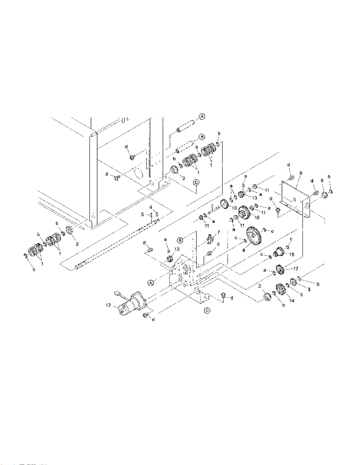
LT-411
Page 16 Konica Business Technologies, Inc. Model LT-411
September, 2000 1st Edition
Page 89

REF. PART NUMBER DESCRIPTION
NO.
1 13GG15111 Driving up/down pulley
2 066077010 Shaft holder (A)
3 192143020 Delivery gear
4 304078040 Pin (B)
5 304078070 Pin (C)
6 540076050 Driving shaft holder
7 08AA85510 Photosensor
8 13GG77010 Sensor detecting gear (Z=92)
9 13LS15030 Driving up/down plate/front
10 25AA77981 Toner supply agitate gear
11 090075530 Shaft holder
12 25AA80172 Paper feed unit motor
13 13LS77030 Motor driving gear /B
14 12QR77060 Up/down gear /C
15 12QR77050 Up/down gear /B
16 192143060 Gear (B)
17 55GA77150 Paper feed driving gear /3
HARDWARE
REF.
LTR.
a 00Z670606
b 00Z670806
c 00Z670406
d 00Z194061
e 00Z474043
PART
NUMBER
Model LT-411 Konica Business Technologies, Inc. Page 17
1st Edition September, 2000
Page 90

Wiring
Page 18 Konica Business Technologies, Inc. Model LT-411
September, 2000 1st Edition
Page 91

REF. PART NUMBER DESCRIPTION
NO.
1 13GG90011 LCT signal wiring/front
2 13GG90030 LCT driving wiring
3 13LS90040 LCT control wiring
4 13LS90020 LCT signal wiring /upper
Model LT-411 Konica Business Technologies, Inc. Page 19
1st Edition September, 2000
Page 92

This page left blank intentionally.
Page 20 Konica Business Technologies, Inc. Model LT-411
September, 2000 1st Edition
Page 93

Alphabetical index
PART PAGE REF.
DESCRIPTION NO. NO.
A
Accessories installing cover 5 21
Actuator . . . . . . . . . . 3 11
Actuator . . . . . . . . . . 7 10
B
Base plate connecting stay
/right . . . . . . . . . . 3 15
Board connecting stay/left . 3 1
Board positioning block . . 15 4
Bottom plate locking plate . 13 15
Bottom plate support part . 3 21
Bushing . . . . . . . . . . 7 32
Bushing . . . . . . . . . . 11 17
C
Cassette pinion (Z=14) . . . 13 13
Clutch changeable cover . . 5 10
Connecting part/A . . . . . 9 3
Connecting part/A . . . . . 11 24
Conveyance driven roller . . 13 4
D
Delivery gear . . . . . . . . 17 3
Door sensor plate assy . . . 3 6
Double feed feeding roller . 11 9
Double feed preventive plate 15 1
Drive up/down wire /A . . . 15 13
Drive up/down wire /B . . . 15 14
Drive up/down wire /C . . . 15 15
Driven pulley . . . . . . . . 15 12
Driving protect cover . . . . 3 2
Driving shaft holder . . . . 7 2
Driving shaft holder . . . . 17 6
Driving up/down plate/front . 17 9
Driving up/down pulley . . . 17 1
Driving up/down wire/D . . . 15 10
E
Entrance guide plate . . . . 7 23
Entrance guide plate/front . 11 18
Entrance guide plate/rear . 9 12
Entrance guide sheet . . . 7 21
Exit guide plate/lower . . . 9 6
F
Fanning drive shaft . . . . . 7 1
Feeding cover assembly . . 9 4
Feeding roller assembly/A . 11 16
Feeding roller assembly/B . 7 22
Feeding roller assembly/B . 11 7
Feeding shaft . . . . . . . 11 5
Front cover . . . . . . . . . 5 8
PART PAGE REF.
DESCRIPTION NO. NO.
Fuse . . . . . . . . . . . . 3 22
G
Gear (B) . . . . . . . . . . 17 16
Guide bearing /A . . . . . . 13 11
Guide bearing /B . . . . . . 13 16
H
Heater cover . . . . . . . . 3 14
Hinge plate/A . . . . . . . . 5 6
I
Idler gear/B (Z=24) . . . . . 7 28
Interlock switch . . . . . . . 3 7
Interlock switch . . . . . . . 7 17
J
Jam door hinge/lower assy . 3 10
Jam open/close door . . . . 5 7
L
LCT control wiring . . . . . 3 17
LCT control wiring . . . . . 19 3
LCT driving board assembly 3 12
LCT driving motor . . . . . 7 6
LCT driving wiring . . . . . 7 18
LCT driving wiring . . . . . 19 2
LCT setting roller/left . . . . 3 19
LCT signal wiring /upper . . 19 4
LCT signal wiring/front . . . 3 9
LCT signal wiring/front . . . 19 1
LCT signal wiring/upper . . 9 18
LCT support part/left . . . . 3 20
Lever auxiliary plate . . . . 11 14
Lever spring . . . . . . . . 11 8
Liftup spring . . . . . . . . 5 11
Lock shaft holder . . . . . . 9 2
M
Magnet catch . . . . . . . . 5 5
Magnet pressure plate . . . 3 16
Main body fixing plate /1 . . 3 23
Main positioning plate . . . 3 3
Motor driving gear /B . . . . 17 13
Mount cover/A . . . . . . . 5 15
Mount cover/B . . . . . . . 5 16
O
Open/close knob . . . . . . 5 17
Open/close lever . . . . . . 9 8
PART PAGE REF.
DESCRIPTION NO. NO.
Open/close spring . . . . . 5 18
Open/shut hinge . . . . . . 5 3
P
Paper conveyance roller . . 9 20
Paper driving belt . . . . . . 11 11
Paper dust scraper . . . . . 9 1
Paper fed heater . . . . . . 3 13
Paper feed auxiliary
cover/front . . . . . . . 5 9
Paper feed clutch . . . . . . 9 22
Paper feed driving cover/2 . 7 29
Paper feed driving gear /3 . 17 17
Paper feed driving gear/B
(Z=22/30) . . . . . . . . 7 7
Paper feed driving gear/C
(Z=22) . . . . . . . . . 7 8
Paper feed driving plate assy 7 13
Paper feed driving shaft/A . 9 16
Paper feed guide plate/upper 9 13
Paper feed holder plate . . . 11 4
Paper feed holder plate/lower 7 33
Paper feed indication label/4 5 20
Paper feed input shaft/1 . . 7 9
Paper feed liftup lever . . . 11 13
Paper feed pressure
spring/front . . . . . . . 9 10
Paper feed pressure
spring/rear . . . . . . . 9 11
Paper feed reversal gear/A
(Z=60) . . . . . . . . . 7 11
Paper feed reversal gear/C
(Z=14) . . . . . . . . . 7 27
Paper feed reversal gear/D
(Z=19) . . . . . . . . . 7 25
Paper feed shaft holder . . . 7 14
Paper feed shaft holder/B . . 9 21
Paper feed standard actuator 11 1
Paper feed unit motor . . . . 17 12
Paper feeding roller/A . . . . 11 15
Paper feeding shaft holder . 11 3
Paper feeding shaft holder . 11 20
Paper guide knob . . . . . . 5 12
Paper guide seal . . . . . . 13 8
Paper positioning plate . . . 13 7
Paper stopper plate . . . . . 13 2
Paper supply cover . . . . . 5 1
Paper supply label . . . . . 5 19
Paper supply side plate . . . 13 9
Paper up/down plate . . . . 15 2
Photosensor . . . . . . . . 3 5
Photosensor . . . . . . . . 7 15
Photosensor . . . . . . . . 9 15
Photosensor . . . . . . . . 9 19
Photosensor . . . . . . . . 17 7
Pickup solenoid . . . . . . . 11 19
Pin . . . . . . . . . . . . . 7 19
Pin (B) . . . . . . . . . . . 7 5
Pin (B) . . . . . . . . . . . 11 6
Pin (B) . . . . . . . . . . . 17 4
Pin (C) . . . . . . . . . . . 17 5
Positioning screw . . . . . . 11 23
Model LT-411 Konica Business Technologies, Inc. Page 21
1st Edition September, 2000
Page 94

PART PAGE REF.
DESCRIPTION NO. NO.
Pressure plate/B . . . . . . 11 25
Pressure plate/L . . . . . . 11 26
Pulley/1 . . . . . . . . . . . 11 12
R
Rack plate (front) . . . . . . 13 12
Rear cover . . . . . . . . . 5 13
Rear guide arm /rear
assembly . . . . . . . . 13 20
Rear guide arm/front
assembly . . . . . . . . 13 5
Rear slide plate . . . . . . . 13 19
Resist driving gear (Z=14) . 7 4
Resist idler gear (Z=42/21) . 7 12
Resist pressure spring . . . 13 6
Reversal roller . . . . . . . 7 24
Reversal spring/B . . . . . . 7 31
Roller collar . . . . . . . . . 11 10
S
Scale plate fixed screw . . . 13 18
Sensor detecting gear (Z=92) 17 8
PART PAGE REF.
DESCRIPTION NO. NO.
Sensor detecting plate . . 15 9
Sensor fixed plate . . . . . 3 4
Sensor fixed plate . . . . . 7 16
Sensor mount plate/A . . . 9 14
Sensor support plate/lower 3 18
Shaft holder . . . . . . . . 9 17
Shaft holder . . . . . . . . 17 11
Shaft holder (A) . . . . . . 17 2
Shaft stopper . . . . . . . 9 5
Shaft support plate . . . . 7 3
Shaft support plate /A . . . 13 17
Side connecting plate . . . 13 14
Side cover/right . . . . . . 5 14
Side fixed plate . . . . . . 13 10
Slide shaft holder . . . . . 13 3
Snap ring . . . . . . . . . 7 20
Snap ring . . . . . . . . . 11 2
Solenoid stopper sheet . . 11 21
Spacer . . . . . . . . . . . 7 30
Spacer plate . . . . . . . . 15 3
Spring guide . . . . . . . . 9 9
Spring mount plate . . . . 5 4
Stopper . . . . . . . . . . 5 2
Stopper rubber . . . . . . 9 7
Stopper rubber . . . . . . 13 1
Switch lever/1 . . . . . . . 11 22
PART PAGE REF.
DESCRIPTION NO. NO.
Switch/1 . . . . . . . . . . 3 8
T
Toner supply agitate gear . 17 10
Toque limiter . . . . . . . . 7 26
Torque drive shaft assembly 7 34
U
Up/down gear /B . . . . . . 17 15
Up/down gear /C . . . . . . 17 14
Up/down spring . . . . . . 15 8
W
Wire fixed plate/A assy . . 15 6
Wire fixed plate/B assy . . 15 7
Wire holder/A . . . . . . . 15 11
Wire mount plate assy . . . 15 16
Wire pulley . . . . . . . . . 15 5
Page 22 Konica Business Technologies, Inc. Model LT-411
September, 2000 1st Edition
Page 95

Numerical index
Retail price list
PART PAGE REF.SUGGESTED
NUMBER NO. NO. RETAIL
008478610 . . . . 7 32
048645260 . . . . 9 7
050011160 . . . . 5 5
059076510 . . . . 11 12
066077010 . . . . 17 2
067642850 . . . . 15 3
08AA85510 . . . 3 5
08AA85510 . . . 7 15
08AA85510 . . . 9 15
08AA85510 . . . 17 7
090075530 . . . . 9 17
090075530 . . . . 17 11
098030300 . . . . 7 19
129R10210 . . . 3 23
129X48350 . . . 13 11
129X48360 . . . 13 16
12AJ12110 . . . . 5 6
12AJ12240 . . . 5 15
12AJ12251 . . . 5 16
12AJ12261 . . . 5 17
12AJ12270 . . . 5 18
12AJ45850 . . . 13 1
12AR10361 . . . 3 16
12AR45611 . . . 3 11
12AR45611 . . . 7 10
12QR77050 . . . 17 15
12QR77060 . . . 17 14
12QR86010 . . . 3 7
12QR86010 . . . 7 17
12TR10110 . . . 3 20
12UM10090 . . . 3 19
12UM12100 . . . 5 2
12UM40220 . . . 5 11
131075510 . . . . 11 17
13GG-1070 . . . 3 6
13GG-1090 . . . 3 10
13GG-1241 . . . 9 4
13GG-1640 . . . 7 1
13GG-1650 . . . 9 16
13GG-1660 . . . 7 13
13GG-4231 . . . 11 5
13GG-4240 . . . 7 34
13GG10051 . . . 3 1
13GG10110 . . . 3 3
13GG10120 . . . 3 4
13GG10120 . . . 7 16
13GG10140 . . . 3 18
13GG10150 . . . 3 21
13GG10190 . . . 3 2
13GG12032 . . . 5 14
13GG12050 . . . 5 7
13GG12060 . . . 5 9
13GG12091 . . . 5 10
13GG12130 . . . 5 12
13GG15111 . . . 17 1
13GG16050 . . . 7 9
13GG40011 . . . 9 13
13GG40041 . . . 9 6
13GG40050 . . . 9 20
13GG40060 . . . 7 23
13GG40070 . . . 11 18
13GG40080 . . . 9 12
PART PAGE REF.SUGGESTED
NUMBER NO. NO. RETAIL
13GG40130 . . . 11 8
13GG40140 . . . 9 11
13GG40150 . . . 9 10
13GG40160 . . . 11 26
13GG40181 . . . 11 4
13GG40200 . . . 9 14
13GG42011 . . . 13 2
13GG42042 . . . 13 9
13GG42081 . . . 13 10
13GG42141 . . . 15 4
13GG77010 . . . 17 8
13GG77770 . . . 7 12
13GG79070 . . . 7 7
13GG79080 . . . 7 8
13GG82010 . . . 9 22
13GG90011 . . . 3 9
13GG90011 . . . 19 1
13GG90030 . . . 7 18
13GG90030 . . . 19 2
13GG97060 . . . 5 20
13LS-4090 . . . . 13 20
13LS-4100 . . . . 13 5
13LS-4310 . . . . 13 19
13LS-9010 . . . . 3 12
13LS10040 . . . . 3 15
13LS12010 . . . . 5 1
13LS12020 . . . . 5 8
13LS12040 . . . . 5 13
13LS12110 . . . . 5 3
13LS15030 . . . . 17 9
13LS15120 . . . . 15 13
13LS15130 . . . . 15 14
13LS15140 . . . . 15 15
13LS15150 . . . . 15 10
13LS42020 . . . . 15 2
13LS42070 . . . . 13 7
13LS42200 . . . . 13 17
13LS42260 . . . . 13 14
13LS42270 . . . . 13 15
13LS77030 . . . . 17 13
13LS80010 . . . . 7 6
13LS90020 . . . . 9 18
13LS90020 . . . . 19 4
13LS90040 . . . . 3 17
13LS90040 . . . . 19 3
13LS97010 . . . . 5 19
190040921 . . . . 13 18
192143020 . . . . 17 3
192143060 . . . . 17 16
197545110 . . . . 11 10
25AA-4730 . . . . 15 16
25AA-4760 . . . . 15 6
25AA-4780 . . . . 15 7
25AA40120 . . . 7 30
25AA40742 . . . 9 3
25AA40742 . . . 11 24
25AA40870 . . . 11 22
25AA41120 . . . 15 12
25AA41180 . . . 15 11
25AA42570 . . . 15 5
25AA42800 . . . 15 8
25AA47700 . . . 9 9
PART PAGE REF.SUGGESTED
NUMBER NO. NO. RETAIL
25AA48900 . . . . 9 8
25AA75090 . . . . 7 14
25AA75530 . . . . 13 3
25AA77981 . . . . 17 10
25AA80172 . . . . 17 12
25AA83060 . . . . 3 13
25AA85010 . . . . 3 8
25AA85511 . . . . 9 19
25AA97320 . . . . 13 8
25BA47230 . . . . 13 12
25BA77301 . . . . 13 13
25SA50530 . . . . 5 4
25SA77561 . . . . 11 11
304078040 . . . . 7 5
304078040 . . . . 17 4
304078070 . . . . 17 5
396040681 . . . . 7 20
396040681 . . . . 11 2
396078020 . . . . 11 6
466076020 . . . . 11 20
50BA40220 . . . . 7 24
540076050 . . . . 7 2
540076050 . . . . 17 6
55FA58190 . . . . 7 26
55GA77150 . . . 17 17
55VA-4550 . . . . 9 1
55VA-4600 . . . . 11 19
55VA-4830 . . . . 7 22
55VA-4830 . . . . 11 7
55VA-4840 . . . . 11 16
55VA12401 . . . . 5 21
55VA40130 . . . . 11 15
55VA40150 . . . . 11 9
55VA40170 . . . . 13 4
55VA40190 . . . . 7 33
55VA40230 . . . . 11 13
55VA40260 . . . . 11 3
55VA40310 . . . . 7 31
55VA40440 . . . . 11 25
55VA40930 . . . . 15 1
55VA40990 . . . . 11 14
55VA41220 . . . . 11 1
55VA41411 . . . . 7 21
55VA42060 . . . . 7 3
55VA42110 . . . . 11 21
55VA42120 . . . . 9 5
55VA42220 . . . . 11 23
55VA42250 . . . . 7 29
55VA42260 . . . . 3 14
55VA43360 . . . . 9 2
55VA44140 . . . . 15 9
55VA46490 . . . . 13 6
55VA75540 . . . . 9 21
55VA77680 . . . . 7 4
55VA79010 . . . . 7 11
55VA79030 . . . . 7 27
55VA79050 . . . . 7 28
55VA79140 . . . . 7 25
963003200 . . . . 3 22
Model LT-411 Konica Business Technologies, Inc. Page 23
1st Edition September, 2000
Page 96

This page left blank intentionally.
Page 24 Konica Business Technologies, Inc. Model LT-411
September, 2000 1st Edition
 Loading...