

Page 1
© EASTMAN KODAK COMPANY, 2005 HEALTH GROUP
Confidential
Restricted
Information
{Diagnostics}{Production}{Health Group}{ExternalAndInternal}
DIAGNOSTICS
for the
Kodak DirectView CR 825/850 SYSTEMS
Service Codes: 5634, 4825
Important
Qualified service personnel must repair this equipment.
Publication No. DG4825-1
10DEC05
Supersedes DG4825-1
20JUL04
H177_0500GC
Page 2

DIAGNOSTICS
10DEC05
DG4825-1
Page
2 of 180
PLEASE NOTE The information contained herein is based on the experience and knowledge relating to the
subject matter gained by Eastman Kodak Company prior to publication.
No patent license is granted by this information.
Eastman Kodak Company reserves the right to change this information without notice, and
makes no warranty, express or implied, with respect to this information. Kodak shall not be
liable for any loss or damage, including consequential or special damages, resulting from any
use of this information, even if loss or damage is caused by Kodak’s negligence or other fault.
This equipment includes parts and assemblies sensitive to damage from electrostatic
discharge. Use caution to prevent damage during all service procedures.
Table of Contents
Description Page
Using the Diagnostics . . . . . . . . . . . . . . . . . . . . . . . . . . . . . . . . . . . . . . . . . . . . . . . . . . 10
System Service Diagnostic Screen. . . . . . . . . . . . . . . . . . . . . . . . . . . . . . . . . . . . 10
Functions of the “System Service Diagnostic” Screen . . . . . . . . . . . . . . . . . . . 12
Diagnostic Tests . . . . . . . . . . . . . . . . . . . . . . . . . . . . . . . . . . . . . . . . . . . . . . . . . . . 24
Individual Component Control. . . . . . . . . . . . . . . . . . . . . . . . . . . . . . . . . . . . 24
Component Control: Step . . . . . . . . . . . . . . . . . . . . . . . . . . . . . . . . . . . . . . . 28
Light Test. . . . . . . . . . . . . . . . . . . . . . . . . . . . . . . . . . . . . . . . . . . . . . . . . . . . . 31
Slow Scan Current and Velocity Tests. . . . . . . . . . . . . . . . . . . . . . . . . . . . . 33
Laser Power . . . . . . . . . . . . . . . . . . . . . . . . . . . . . . . . . . . . . . . . . . . . . . . . . . . 35
Galvo Test . . . . . . . . . . . . . . . . . . . . . . . . . . . . . . . . . . . . . . . . . . . . . . . . . . . . 36
PMT Test . . . . . . . . . . . . . . . . . . . . . . . . . . . . . . . . . . . . . . . . . . . . . . . . . . . . . 39
GALVO PLOT . . . . . . . . . . . . . . . . . . . . . . . . . . . . . . . . . . . . . . . . . . . . . . . . . . 40
Transport . . . . . . . . . . . . . . . . . . . . . . . . . . . . . . . . . . . . . . . . . . . . . . . . . . . . . 43
AUTOLOOPER . . . . . . . . . . . . . . . . . . . . . . . . . . . . . . . . . . . . . . . . . . . . . . . . . 45
MCPU Self Test . . . . . . . . . . . . . . . . . . . . . . . . . . . . . . . . . . . . . . . . . . . . . . . . 47
Diagnostic Procedures . . . . . . . . . . . . . . . . . . . . . . . . . . . . . . . . . . . . . . . . . . . . . . 49
Checking the Error Logs . . . . . . . . . . . . . . . . . . . . . . . . . . . . . . . . . . . . . . . . 49
Checking the Error Frequency Log . . . . . . . . . . . . . . . . . . . . . . . . . . . . . . . 50
Checking the Actuation Logs . . . . . . . . . . . . . . . . . . . . . . . . . . . . . . . . . . . . 51
Storing the Error Logs on a Disk . . . . . . . . . . . . . . . . . . . . . . . . . . . . . . . . . 52
Clearing the Error Logs . . . . . . . . . . . . . . . . . . . . . . . . . . . . . . . . . . . . . . . . . 53
Installing Files from a Disk . . . . . . . . . . . . . . . . . . . . . . . . . . . . . . . . . . . . . . 54
Displaying the Software Versions. . . . . . . . . . . . . . . . . . . . . . . . . . . . . . . . . 55
Downloading Software to the BOARDS . . . . . . . . . . . . . . . . . . . . . . . . . . . . 56
Error Codes . . . . . . . . . . . . . . . . . . . . . . . . . . . . . . . . . . . . . . . . . . . . . . . . . . . . . . . . . . . 57
Page 3

DIAGNOSTICS
10DEC05
DG4825-1
Page
3 of 180
Overview. . . . . . . . . . . . . . . . . . . . . . . . . . . . . . . . . . . . . . . . . . . . . . . . . . . . . . . . . . 57
CASSETTE LOAD . . . . . . . . . . . . . . . . . . . . . . . . . . . . . . . . . . . . . . . . . . . . . . . . . . 58
10006 - CASSETTE REAR SENSOR S3 did not detect CASSETTE . . . . . 58
10007 - CASSETTE REAR SENSOR S3 did not detect loading of
CASSETTE . . . . . . . . . . . . . . . . . . . . . . . . . . . . . . . . . . . . . . . . . . . . . . . . . . 58
10008 - CASSETTE REAR SENSOR S3 did not clear . . . . . . . . . . . . . . . . . 59
10009 - CASSETTE LOAD SENSOR S2 did not clear . . . . . . . . . . . . . . . . . 60
10014 - CASSETTE REAR SENSOR S3 blocked on load . . . . . . . . . . . . . . 61
10016 - Load CASSETTE: Retry attempt . . . . . . . . . . . . . . . . . . . . . . . . . . . 61
10017 - Eject CASSETTE: Retry attempt . . . . . . . . . . . . . . . . . . . . . . . . . . . 62
10019 - Eject CASSETTE: Timeout error . . . . . . . . . . . . . . . . . . . . . . . . . . . 62
10020 - Malfunction at CASSETTE ENTRY SENSOR S1 . . . . . . . . . . . . . . 63
10021 - MSC BOARD A1: Software malfunction . . . . . . . . . . . . . . . . . . . . . 63
10022 - MSC BOARD A1: Software malfunction . . . . . . . . . . . . . . . . . . . . . 64
10024 - MSC BOARD A1: Software malfunction . . . . . . . . . . . . . . . . . . . . . 64
10029 - READER detected the CASSETTE BAR CODE label as backward 64
10030 - READER did not read the CASSETTE BAR CODE . . . . . . . . . . . . 64
LATCH/UNLATCH CAM. . . . . . . . . . . . . . . . . . . . . . . . . . . . . . . . . . . . . . . . . . . . . . 66
11001 - DUPLEX CAM did not move to Home Position. . . . . . . . . . . . . . . 66
11002 - DUPLEX CAM did not move to “PINCH” position . . . . . . . . . . . . . 66
11003 - DUPLEX CAM did not move to “CLAMP/UNLATCH” position . . . 66
11004 - DUPLEX CAM did not move to “UNCLAMP/LATCH” position. . . 66
11005 - DUPLEX CAM did not move to “UNPINCH” position . . . . . . . . . . 66
11006 - CAM OUTER SENSOR S11 did not detect position of
DUPLEX CAM. . . . . . . . . . . . . . . . . . . . . . . . . . . . . . . . . . . . . . . . . . . . . . . . 66
11007 - CAM INNER SENSOR S10 did not detect Home Position for DUPLEX
CAM . . . . . . . . . . . . . . . . . . . . . . . . . . . . . . . . . . . . . . . . . . . . . . . . . . . . . . . 66
11009 - DUPLEX CAM: Move failed. . . . . . . . . . . . . . . . . . . . . . . . . . . . . . . . 67
11010 - DUPLEX CAM: Software command failed on the MSC BD . . . . . 67
11014 - DUPLEX CAM: Timeout Error . . . . . . . . . . . . . . . . . . . . . . . . . . . . . 67
11015 - Move command failed because SLOW SCAN not at Home Position 67
11016 - MSC BOARD A1: Software Error for DUPLEX CAM . . . . . . . . . . . 67
11017 - MSC BOARD A1: Software Error for DUPLEX CAM . . . . . . . . . . . 68
11018 - DUPLEX CAM did not move to next position . . . . . . . . . . . . . . . . 68
11019 - DUPLEX CAM did not move to “PINCH” position . . . . . . . . . . . . . 68
11020 - DUPLEX CAM did not move to “UNLATCH” position. . . . . . . . . . 68
11021 - DUPLEX CAM did not move to “LATCH” position . . . . . . . . . . . . 69
11022 - DUPLEX CAM did not move to “UNPINCH” position . . . . . . . . . . 69
SLOW SCAN AY . . . . . . . . . . . . . . . . . . . . . . . . . . . . . . . . . . . . . . . . . . . . . . . . . . . 69
12001 - SLOW SCAN EXTRACTION BAR did not move to Home Position 69
12002 - EXTRACTION BAR REFERENCE SENSOR S9 failed to activate. 70
12003 - PLATE PRESENT SENSOR S5 did not detect PLATE . . . . . . . . . 70
Page 4

DIAGNOSTICS
10DEC05
DG4825-1
Page
4 of 180
12004 - PLATE PRESENT SENSOR S5 failed to activate . . . . . . . . . . . . . . 71
12009 - Caution! SLOW SCAN MOTOR drawing too much power . . . . . . 71
12012 - SLOW SCAN AY: Timeout Error . . . . . . . . . . . . . . . . . . . . . . . . . . . 72
12013 - SLOW SCAN AY: Timeout error . . . . . . . . . . . . . . . . . . . . . . . . . . . 72
12014 - MSC BOARD A1: Software Error for SLOW SCAN . . . . . . . . . . . . 72
12100 - SLOW SCAN CONTROLLER BOARD A6: Software Error . . . . . . 72
12101 - SLOW SCAN a velocity malfunction during scan. . . . . . . . . . . . . 73
12102 - SLOW SCAN stopped during scan . . . . . . . . . . . . . . . . . . . . . . . . . 73
12103 - SLOW SCAN stopped during scan . . . . . . . . . . . . . . . . . . . . . . . . . 73
12104 - SLOW SCAN: Timeout while moving to SENSOR S9 . . . . . . . . . . 73
12107 - SLOW SCAN: +24 V DC malfunction during scan. . . . . . . . . . . . . 74
12108 - SLOW SCAN stopped during scan . . . . . . . . . . . . . . . . . . . . . . . . . 74
12109 - SLOW SCAN stopped during scan . . . . . . . . . . . . . . . . . . . . . . . . . 74
12110 - SLOW SCAN did not communicate with the MOTION SYSTEM
CONTROL. . . . . . . . . . . . . . . . . . . . . . . . . . . . . . . . . . . . . . . . . . . . . . . . . . . 74
12111 - SLOW SCAN did not move. . . . . . . . . . . . . . . . . . . . . . . . . . . . . . . . 74
12112 - SLOW SCAN did not move. . . . . . . . . . . . . . . . . . . . . . . . . . . . . . . . 75
12113 - SLOW SCAN CONTROLLER BOARD A6: NVRAM malfunctioned 75
12115 - SLOW SCAN CONTROLLER BOARD A6: Software Error . . . . . . 75
12116 - SLOW SCAN CONTROLLER BOARD A6 did not communicate with
MSC. . . . . . . . . . . . . . . . . . . . . . . . . . . . . . . . . . . . . . . . . . . . . . . . . . . . . . . . 75
12120 - SLOW SCAN did not move. . . . . . . . . . . . . . . . . . . . . . . . . . . . . . . . 76
12121 - SLOW SCAN did not move. . . . . . . . . . . . . . . . . . . . . . . . . . . . . . . . 76
12122 - SLOW SCAN COIL BOARD A7 malfunctioned. . . . . . . . . . . . . . . . 76
12123 - SLOW SCAN CONTROLLER BOARD A6: Software Error . . . . . . 76
12124 - SLOW SCAN CONTROLLER BOARD A6: Software Error . . . . . . 76
12125 - SLOW SCAN COIL BOARD A7 malfunctioned. . . . . . . . . . . . . . . . 77
12126 - Caution! SLOW SCAN MOTOR is overheated . . . . . . . . . . . . . . . . 77
12130 - SLOW SCAN CONTROLLER BOARD A6: Software Error . . . . . . 77
12131 - SLOW SCAN CONTROLLER BOARD A6 did not communicate with
MSC. . . . . . . . . . . . . . . . . . . . . . . . . . . . . . . . . . . . . . . . . . . . . . . . . . . . . . . . 77
12132 - SLOW SCAN CONTROLLER BOARD A6 did not communicate with
MSC. . . . . . . . . . . . . . . . . . . . . . . . . . . . . . . . . . . . . . . . . . . . . . . . . . . . . . . . 78
12201 - SLOW SCAN CONTROLLER BOARD A6: Programming Error . . 78
12202 to 12260 - SLOW SCAN CONTROLLER BOARD A6: “Memory
Command” Error. . . . . . . . . . . . . . . . . . . . . . . . . . . . . . . . . . . . . . . . . . . . . 78
12896 - SLOW SCAN CONTROLLER BOARD A6: Unexpected Reset . . . 80
12901 - SLOW SCAN CONTROLLER BOARD A6: Unexpected Retry . . . . 80
12902 - SLOW SCAN CONTROLLER BOARD A6: Unexpected Retry . . . . 80
12903 - SLOW SCAN CONTROLLER BOARD A6: Unexpected Retry . . . . 81
12904 - SLOW SCAN CONTROLLER BOARD A6: Unexpected Retry . . . . 81
12905 - SLOW SCAN CONTROLLER BOARD A6: Unexpected Retry . . . . 81
Page 5

DIAGNOSTICS
10DEC05
DG4825-1
Page
5 of 180
12906 - SLOW SCAN CONTROLLER BOARD A6: Unexpected Retry . . . . 81
12907 - SLOW SCAN CONTROLLER BOARD A6: Unexpected Retry . . . . 82
12908 - SLOW SCAN CONTROLLER BOARD A6: Unexpected Retry . . . . 82
12911 - SLOW SCAN CONTROLLER BOARD A6: Unexpected Retry . . . . 82
12913 - SLOW SCAN CONTROLLER BOARD A6: Unexpected Retry . . . . 82
12914 - SLOW SCAN CONTROLLER BOARD A6: Unexpected Retry . . . . 83
12915 - SLOW SCAN CONTROLLER BOARD A6: Unexpected Retry . . . . 83
12930 - SLOW SCAN: Unexpected Retry during Current Test . . . . . . . . . 83
12931 - SLOW SCAN: Unexpected Retry during Velocity Test. . . . . . . . . 83
12941 - Unexpected Retry during Communication to MOTION SYSTEM
CONTROL BD . . . . . . . . . . . . . . . . . . . . . . . . . . . . . . . . . . . . . . . . . . . . . . . 84
ERASE LAMPS . . . . . . . . . . . . . . . . . . . . . . . . . . . . . . . . . . . . . . . . . . . . . . . . . . . . 84
13001 - 13008 ERASE LAMP PAIRS . . . . . . . . . . . . . . . . . . . . . . . . . . . . . . . 84
13009 - All ERASE LAMPS malfunctioned. . . . . . . . . . . . . . . . . . . . . . . . . . 85
13010 - Erase time exceeds maximum allowed. . . . . . . . . . . . . . . . . . . . . . 86
13011 - Command to Erase did not occur . . . . . . . . . . . . . . . . . . . . . . . . . . 86
13012 - MSC BOARD A1: Invalid Command for ERASE LAMPS . . . . . . . 86
13013 - MSC BOARD A1: Software failure during erase . . . . . . . . . . . . . . 86
13899 - General Erase Error . . . . . . . . . . . . . . . . . . . . . . . . . . . . . . . . . . . . . 86
POWER SUPPLY . . . . . . . . . . . . . . . . . . . . . . . . . . . . . . . . . . . . . . . . . . . . . . . . . . . 86
14001 - SLOW SCAN: Malfunction of 24 V Power . . . . . . . . . . . . . . . . . . . 86
14002 - STEPPER: Malfunction of 24 V Power . . . . . . . . . . . . . . . . . . . . . . 87
14003 - CAM MOTOR M1: Low Power Malfunction. . . . . . . . . . . . . . . . . . . 87
14005 - Front DOOR Open. . . . . . . . . . . . . . . . . . . . . . . . . . . . . . . . . . . . . . . 87
14006 - DUPLEX CAM: Initialization Error due to the PLATE PRESENT
SENSOR S5 reading blocked when the SLOW SCAN AY is in the home
position. . . . . . . . . . . . . . . . . . . . . . . . . . . . . . . . . . . . . . . . . . . . . . . . . . . . . 88
14008 - SLOW SCAN: Initialization Error. . . . . . . . . . . . . . . . . . . . . . . . . . . 88
14009 - DUPLEX CAM: Initialization Error . . . . . . . . . . . . . . . . . . . . . . . . . . 88
14010 - Slow Scan Async Reset Error . . . . . . . . . . . . . . . . . . . . . . . . . . . . . 88
DATA PATH . . . . . . . . . . . . . . . . . . . . . . . . . . . . . . . . . . . . . . . . . . . . . . . . . . . . . . 89
15001 - MCPU BOARD A2: Fatal Error in Software . . . . . . . . . . . . . . . . . . 89
15002 - MCPU BOARD A2: Fatal Error in Software . . . . . . . . . . . . . . . . . . 89
15003 - MCPU BOARD A2: Communications Error in Software . . . . . . . . 89
15005 - LASER: Reference Error. . . . . . . . . . . . . . . . . . . . . . . . . . . . . . . . . . 89
15006 - Communications Error between MCPU BD A2 and GALVO BD A4 90
15007 - Communications Error between MCPU BD A2 and GALVO BD A4 91
15008 - Start of Scan Timeout . . . . . . . . . . . . . . . . . . . . . . . . . . . . . . . . . . . . 91
15012 - Communications Error between MCPU BOARD A2 and the PC . 91
15013 - Image Quality Warning . . . . . . . . . . . . . . . . . . . . . . . . . . . . . . . . . . . 92
15014 - LASER power not calibrated . . . . . . . . . . . . . . . . . . . . . . . . . . . . . . 92
15015 - PLATE not calibrated . . . . . . . . . . . . . . . . . . . . . . . . . . . . . . . . . . . . 92
Page 6

DIAGNOSTICS
10DEC05
DG4825-1
Page
6 of 180
15016 - The LASER reference voltage is too high . . . . . . . . . . . . . . . . . . . 93
15017 - PLATE not calibrated . . . . . . . . . . . . . . . . . . . . . . . . . . . . . . . . . . . . 93
15018 - There was an error reading or writing to the PCMCIA card . . . . 93
15040 - Communications Error Between MCPU and the PC . . . . . . . . . . . 93
15800 - Image resent at NT reboot . . . . . . . . . . . . . . . . . . . . . . . . . . . . . . . . 94
15900 - NT rejected image at end of scan. Retransmission being
attempted . . . . . . . . . . . . . . . . . . . . . . . . . . . . . . . . . . . . . . . . . . . . . . . . . . . 94
Calibration . . . . . . . . . . . . . . . . . . . . . . . . . . . . . . . . . . . . . . . . . . . . . . . . . . . . . . . . 95
16001 - Calibration Error: Did not find START OF SCAN position . . . . . . 95
16002 - Calibration Error: Did not find Offset . . . . . . . . . . . . . . . . . . . . . . . 95
16003 - Calibration Error: Did not find Amplitude . . . . . . . . . . . . . . . . . . . 95
16005 - Calibration Error: Routine did not receive image in the time
allowed . . . . . . . . . . . . . . . . . . . . . . . . . . . . . . . . . . . . . . . . . . . . . . . . . . . . . 96
16006 - Calibration Error: Did not acquire image . . . . . . . . . . . . . . . . . . . . 97
16010 - Possible Light Leak. . . . . . . . . . . . . . . . . . . . . . . . . . . . . . . . . . . . . . 97
16011 - Imaging System Error occurred during Initialization . . . . . . . . . . 97
16012 - PMT/DAS BOARD A5: Calculation Error occurred during
Initialization . . . . . . . . . . . . . . . . . . . . . . . . . . . . . . . . . . . . . . . . . . . . . . . . . 97
16013 - Imaging System contains out-of-range noise . . . . . . . . . . . . . . . . 98
16014 - Imaging System did not zero or PMT did not calibrate . . . . . . . . 98
16016 - Malfunctioning PMT . . . . . . . . . . . . . . . . . . . . . . . . . . . . . . . . . . . . . 99
16017 - Possible Light Leak. . . . . . . . . . . . . . . . . . . . . . . . . . . . . . . . . . . . . . 99
16018 - Possible Light Leak. . . . . . . . . . . . . . . . . . . . . . . . . . . . . . . . . . . . . . 99
16019 - Calibration could not find offset, rotate GALVO counterclockwise 99
16020 - Calibration could not find offset, rotate GALVO clockwise . . . . . 99
16021 - Malfunctioning PMT1: Gain out of range . . . . . . . . . . . . . . . . . . . . 100
16022 - Malfunctioning PMT2: Gain out of range . . . . . . . . . . . . . . . . . . . . 100
“Self Test” for the MASTER CENTRAL PROCESSING UNIT . . . . . . . . . . . . . . . 101
19001 - Check GALVO COMMUNICATIONS CABLE . . . . . . . . . . . . . . . . . . 101
19002 - Check PMT BOARD CABLE and power . . . . . . . . . . . . . . . . . . . . . 101
19003 - Check the power to the GALVO BOARD . . . . . . . . . . . . . . . . . . . . 101
19004 - GALVO AGC reference is too high. Suggest check if GALVO
connected and/or ad just AGC . . . . . . . . . . . . . . . . . . . . . . . . . . . . . . . . . . 101
19005 - Check the GALVO reference (too low) . . . . . . . . . . . . . . . . . . . . . . 102
19006 - Memory self test failed. Replace the MCPU BOARD . . . . . . . . . . 102
19009 - The LASER diode off power is too high. . . . . . . . . . . . . . . . . . . . . 102
19010 - The LASER diode on power is too low . . . . . . . . . . . . . . . . . . . . . 102
19011 - PMT BOARD ramp test failed. . . . . . . . . . . . . . . . . . . . . . . . . . . . . . 103
MOTION SYSTEM CONTROL BOARD. . . . . . . . . . . . . . . . . . . . . . . . . . . . . . . . . . 103
22000 - MSC BOARD A1: Fatal Software Error . . . . . . . . . . . . . . . . . . . . . . 103
22001 - MSC BOARD A1: Memory did not
erase during Download . . . . . 103
22002 - MSC BOARD A1: Error during download of MSC Software. . . . . 103
Page 7

DIAGNOSTICS
10DEC05
DG4825-1
Page
7 of 180
22003 - MSC BOARD A1: Checksum of Main Application failed . . . . . . . 104
22004 - MSC BOARD A1: RAM Test failed . . . . . . . . . . . . . . . . . . . . . . . . . . 104
22005 - MSC BOARD A1: Error during download of MSC Software. . . . . 105
22006 - MSC BOARD A1: Error during download of MSC Software. . . . . 105
22007 - MSC BOARD A1: Error during download of MSC Software. . . . . 105
22008 - MSC BOARD A1: Error during download of MSC Software. . . . . 105
22009 - MSC BOARD A1: Error during download of MSC Software. . . . . 106
22010 - MSC BOARD A1: Error during download of MSC Software. . . . . 106
22011 - MSC BOARD A1: Error during download of MSC Software. . . . . 107
MOTION SYSTEM CONTROL BOARD RTXC . . . . . . . . . . . . . . . . . . . . . . . . . . . . 107
29001 - 29008 - MSC BOARD A1: Software malfunctioned . . . . . . . . . . . . 107
MOTION SYSTEM CONTROL BOARD SYSTEM. . . . . . . . . . . . . . . . . . . . . . . . . . 108
30002 - 30033 - MSC BOARD A1: Software malfunctioned . . . . . . . . . . . . 108
Communications for the MOTION SYSTEM CONTROL BOARD . . . . . . . . . . . . 110
32001 - Communications malfunctioned between MCPU and
SSC BOARDS . . . . . . . . . . . . . . . . . . . . . . . . . . . . . . . . . . . . . . . . . . . . . . . 110
32002 - MSC BOARD A1: Internal Communications Error . . . . . . . . . . . . . 110
32003 - MSC BOARD A1: Internal Communications Error . . . . . . . . . . . . . 110
32004 - Communications Error between MCPU and SSC BOARDS. . . . . 110
32005 - Communications Error between MCPU and SSC BOARDS. . . . . 111
Shutdown Management . . . . . . . . . . . . . . . . . . . . . . . . . . . . . . . . . . . . . . . . . . . . . 112
47001 - Communications to MCPU BD failed during Shut Down. . . . . . . 112
47002 - Internal communications failure . . . . . . . . . . . . . . . . . . . . . . . . . . . 112
47003 - Internal communications to UPS failed . . . . . . . . . . . . . . . . . . . . . 112
47500 - 47504 - Internal communications to UPS failed . . . . . . . . . . . . . . 112
47510 - 47511 - Internal communications failure to UPS1 . . . . . . . . . . . . . 112
47520 - 47522 - Internal communications failure to UPS1 . . . . . . . . . . . . . 113
47550 - The BATTERY in UPS1 is too low. System will be shutdown in 1
minute. . . . . . . . . . . . . . . . . . . . . . . . . . . . . . . . . . . . . . . . . . . . . . . . . . . . . . 113
47551 - Unable to establish communications with UPS1 . . . . . . . . . . . . . 113
47950 - Display only - no Log Message. . . . . . . . . . . . . . . . . . . . . . . . . . . . 113
47951 - Display only - no Log Message. . . . . . . . . . . . . . . . . . . . . . . . . . . . 113
47952 - Display only - no Log Message. . . . . . . . . . . . . . . . . . . . . . . . . . . . 114
47960 - Display only - no Log Message. . . . . . . . . . . . . . . . . . . . . . . . . . . . 114
47961 - Display only - no Log Message. . . . . . . . . . . . . . . . . . . . . . . . . . . . 114
47962 - Display only - no Log Message. . . . . . . . . . . . . . . . . . . . . . . . . . . . 114
DISK MANAGER . . . . . . . . . . . . . . . . . . . . . . . . . . . . . . . . . . . . . . . . . . . . . . . . . . . 115
49000 - HARD DISK is full. DISK MANAGER not able to remove images 115
49001 - Image Files have been deleted . . . . . . . . . . . . . . . . . . . . . . . . . . . . 115
Installation . . . . . . . . . . . . . . . . . . . . . . . . . . . . . . . . . . . . . . . . . . . . . . . . . . . . . . . . 116
55100 - Error on the Options Diskette or this is not a valid Options
Diskette. . . . . . . . . . . . . . . . . . . . . . . . . . . . . . . . . . . . . . . . . . . . . . . . . . . . . 116
Page 8

DIAGNOSTICS
10DEC05
DG4825-1
Page
8 of 180
55101 - Could not open files on the Options Diskette. Try another Options
Diskette. . . . . . . . . . . . . . . . . . . . . . . . . . . . . . . . . . . . . . . . . . . . . . . . . . . . . 116
55102 - Pentium III identification not enabled on this Pentium III class
machine . . . . . . . . . . . . . . . . . . . . . . . . . . . . . . . . . . . . . . . . . . . . . . . . . . . . 116
55103 - Could not open files on the Options Diskette. . . . . . . . . . . . . . . . 117
55104 - Error updating the options on the CR 825/850 SYSTEM . . . . . . . 117
55105 - Could not allocate essential memory . . . . . . . . . . . . . . . . . . . . . . . 117
55106 - The Options on this diskette are already enabled on this system 117
55107 - This Options Diskette has been used on another device . . . . . . 117
55109 - Error occurred while trying to update the Options on the UNIT . 117
55110 - Could not determine what product we are running on . . . . . . . . 118
55111 - The Options Diskette is not valid for this product . . . . . . . . . . . . 118
55112 - Error obtaining Adapter Name on Pentium 4 class machine . . . 118
55113 - Error obtaining MAC address for card name specified in
AdapterName in General Equipment on Pentium 4 class machine . . . 118
Troubleshooting . . . . . . . . . . . . . . . . . . . . . . . . . . . . . . . . . . . . . . . . . . . . . . . . . . . . . . . 119
Initialization Errors . . . . . . . . . . . . . . . . . . . . . . . . . . . . . . . . . . . . . . . . . . . . . . . . . 119
“Power-On Self-Test” (POST) Errors . . . . . . . . . . . . . . . . . . . . . . . . . . . . . . 119
Software Loading Errors . . . . . . . . . . . . . . . . . . . . . . . . . . . . . . . . . . . . . . . . 120
Application Software Errors. . . . . . . . . . . . . . . . . . . . . . . . . . . . . . . . . . . . . . 121
Dark TOUCH SCREEN . . . . . . . . . . . . . . . . . . . . . . . . . . . . . . . . . . . . . . . . . . 121
Image Quality . . . . . . . . . . . . . . . . . . . . . . . . . . . . . . . . . . . . . . . . . . . . . . . . . . . . . . 121
Checkout Procedures . . . . . . . . . . . . . . . . . . . . . . . . . . . . . . . . . . . . . . . . . . . . . . . . . . . 122
CASSETTE HANDLING AY . . . . . . . . . . . . . . . . . . . . . . . . . . . . . . . . . . . . . . . . . . . 122
DUPLEX CAM. . . . . . . . . . . . . . . . . . . . . . . . . . . . . . . . . . . . . . . . . . . . . . . . . . 122
CAM MOTOR M1 . . . . . . . . . . . . . . . . . . . . . . . . . . . . . . . . . . . . . . . . . . . . . . . 128
PLATE PRESENT SENSOR S5 . . . . . . . . . . . . . . . . . . . . . . . . . . . . . . . . . . . 129
INTERLOCK SWITCH S8. . . . . . . . . . . . . . . . . . . . . . . . . . . . . . . . . . . . . . . . . 132
EXTRACTION BAR SENSOR S9 . . . . . . . . . . . . . . . . . . . . . . . . . . . . . . . . . . 134
HOOKS on the EXTRACTION BAR . . . . . . . . . . . . . . . . . . . . . . . . . . . . . . . . 136
CAM SENSORS S10 and S11. . . . . . . . . . . . . . . . . . . . . . . . . . . . . . . . . . . . . 137
BOARDS. . . . . . . . . . . . . . . . . . . . . . . . . . . . . . . . . . . . . . . . . . . . . . . . . . . . . . . . . . 139
MOTION SYSTEM CONTROL BOARD A1 . . . . . . . . . . . . . . . . . . . . . . . . . . . 139
MASTER CENTRAL PROCESSING UNIT BOARD A2 . . . . . . . . . . . . . . . . . 140
DIGITIZER BOARD A3. . . . . . . . . . . . . . . . . . . . . . . . . . . . . . . . . . . . . . . . . . . 143
GALVO BOARD A4 . . . . . . . . . . . . . . . . . . . . . . . . . . . . . . . . . . . . . . . . . . . . . 145
PMT/DAS BOARD A5 . . . . . . . . . . . . . . . . . . . . . . . . . . . . . . . . . . . . . . . . . . . 147
SLOW SCAN CONTROLLER BOARD A6 and COIL BOARD A7 . . . . . . . . 148
LASER DRIVER BOARD A17 . . . . . . . . . . . . . . . . . . . . . . . . . . . . . . . . . . . . . 152
Power . . . . . . . . . . . . . . . . . . . . . . . . . . . . . . . . . . . . . . . . . . . . . . . . . . . . . . . . . . . . 154
POWER SUPPLY PS1 . . . . . . . . . . . . . . . . . . . . . . . . . . . . . . . . . . . . . . . . . . . 154
TRANSFORMER T1. . . . . . . . . . . . . . . . . . . . . . . . . . . . . . . . . . . . . . . . . . . . . 156
Page 9

DIAGNOSTICS
10DEC05
DG4825-1
Page
9 of 180
UNINTERRUPTED POWER SUPPLY UPS1 . . . . . . . . . . . . . . . . . . . . . . . . . . 158
System Status . . . . . . . . . . . . . . . . . . . . . . . . . . . . . . . . . . . . . . . . . . . . . . . . . . . . . 160
Test Points and LEDs. . . . . . . . . . . . . . . . . . . . . . . . . . . . . . . . . . . . . . . . . . . . . . . . . . . 163
MOTION SYSTEM CONTROL BOARD A1 . . . . . . . . . . . . . . . . . . . . . . . . . . . 163
MASTER CENTRAL PROCESSING UNIT BOARD A2 . . . . . . . . . . . . . . . . . 166
DIGITIZER BOARD A3. . . . . . . . . . . . . . . . . . . . . . . . . . . . . . . . . . . . . . . . . . . 169
GALVO BOARD A4 . . . . . . . . . . . . . . . . . . . . . . . . . . . . . . . . . . . . . . . . . . . . . 171
PMT/DAS BOARD A5 . . . . . . . . . . . . . . . . . . . . . . . . . . . . . . . . . . . . . . . . . . . 173
SLOW SCAN CONTROLLER BOARD A6 . . . . . . . . . . . . . . . . . . . . . . . . . . . 175
LASER DRIVER BOARD A17 . . . . . . . . . . . . . . . . . . . . . . . . . . . . . . . . . . . . . 177
LASER DRIVER PREREGULATOR BOARD A18 . . . . . . . . . . . . . . . . . . . . . 179
Page 10

10DEC05
DG4825-1
Page
10 of 180
DIAGNOSTICS Using the Diagnostics
Section 1: Using the Diagnostics
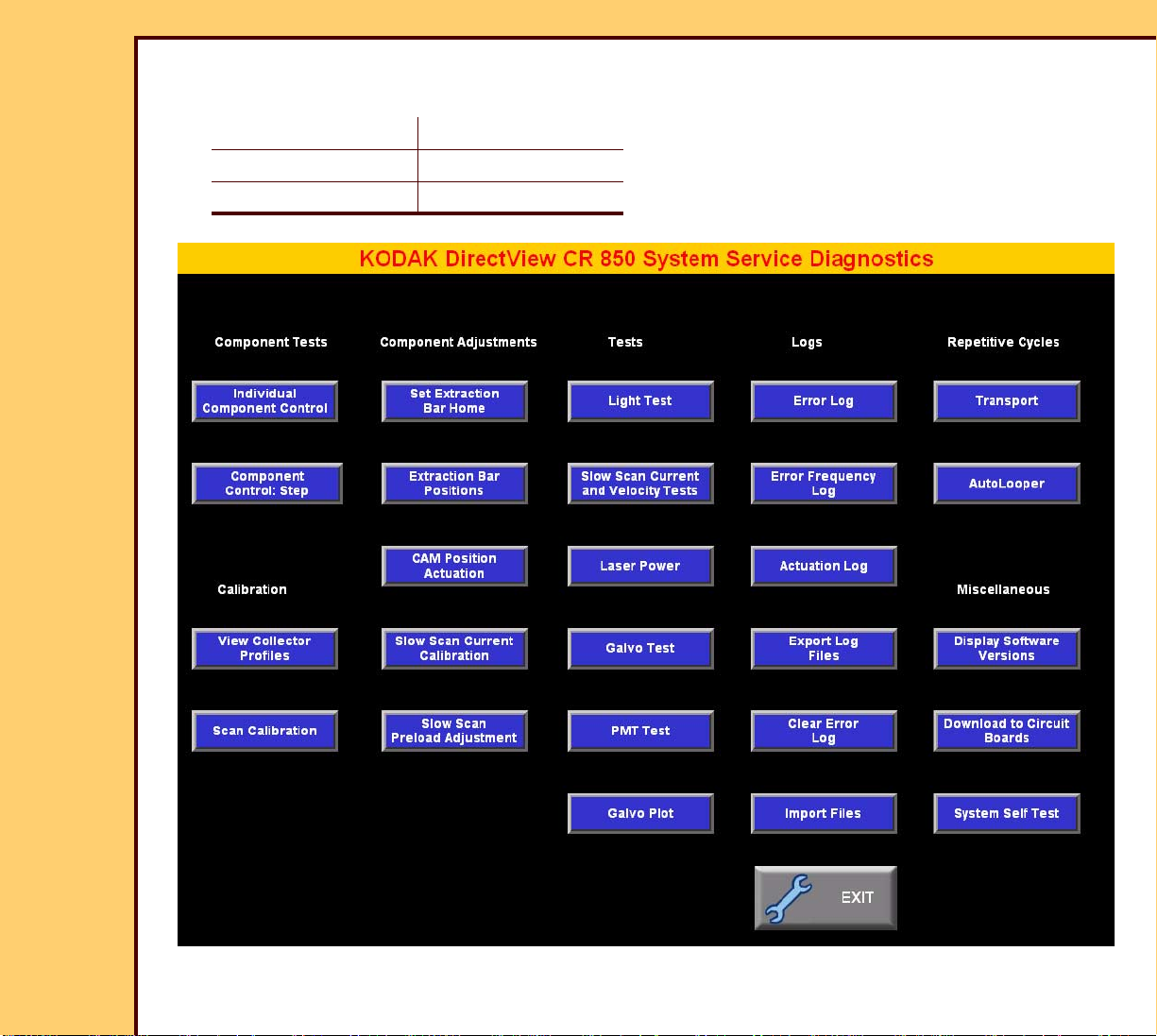
System Service Diagnostic Screen
Important
For systems with Software Version ≥ 4.1, you must have a “Session ID” for access to
“Service Functions” and “Diagnostics”. See SERVICE BULLETIN 843.
1 At the main menu, touch:
• [Service Functions]
• [ENTER]
• [Diagnostics]
2 Does the “System Service Diagnostics” screen display?
Yes No
Advance to the test or procedure. Continue with Step 3.
3 Check that the TX and RX LEDs are blinking on the MASTER CENTRAL PROCESSING
UNIT BOARD A2 and on the NETWORK CARD in the computer.
4 At the main menu, touch [Service Functions].
5 At the main menu, touch:
• [Service Functions]
• [ENTER]
• [EXIT TO DESKTOP]
6 Select My Computer>Control Panel>Network>Protocols.
7 Double-click [TCP/IP Protocol].
8 Select [ADAPTER 1].
Page 11
DIAGNOSTICS Using the Diagnostics
10DEC05
DG4825-1
Page
11 of 180
9 Check the “IP Address” of the NETWORK CARD that is connected to the MASTER
CENTRAL PROCESSING UNIT BOARD A2:
“IP Address” 192.168.0.1
“Subnet Mask” 255.255.255.0
“Default Gateway”
Page 12
10DEC05
DG4825-1
Page
12 of 180
DIAGNOSTICS Using the Diagnostics
Functions of the “System Service Diagnostic” Screen
Table 1 Component Tests
BUTTON Description
[Individual Component Control]
Important
For the test procedure, see Individual Component
Control.
Allows you to actuate and check the status of:
• CAM MOTO R
• SLOW SCAN
• ERASE LAMPS
• CASSETTE DRIVE MOTOR
[Component Control: Step]
Important
For the test procedure, see Component Control: Step.
Allows you to check the status of the components by
executing the following steps:
1. Loading the CASSETTE
2. Loading the PLATE
3. Scanning the PLATE
4. Erasing the PLATE
5. Ejecting the PLATE
6. Ejecting the CASSETTE
Page 13
DIAGNOSTICS Using the Diagnostics
10DEC05
DG4825-1
Page
13 of 180
Table 2 Calibration
BUTTON Description
[View Collector Profiles]
Important
For the procedure, see Calibration for the CR 825/850 SYSTEM.
Displays the COLLECTOR PROFILE for each size of CASSETTE,
including:
• number of steps from “HOME” to “START OF SCAN”
• “OFFSET” - Number of pixels from “START” to the diagnostic
image
• “Amplitude” - Number of pixels from “OFFSET” to the last pixe l
of the diagnostic image
• PMT 1 - 2: Correction value of each PMT for gain adjustment
[Scan Calibration]
Caution
• All COVERS must be installed when using this option.
• For the procedure, see Calibration for the CR 825/850
SYSTEM.
• Completes the calibration of:
– GALVO
– PMT 1
– PMT 2
• Starts a COLLECTOR PROFILE for all sizes of STORAGE
PHOSPHOR PLATES.
• Allows calibration of the PLATES exposed at 20 mR
± 5 mR.
• Displays the date and time of the last successful calibration.
Page 14

DIAGNOSTICS Using the Diagnostics
10DEC05
DG4825-1
Page
14 of 180
Table 3 Component Adjustments
BUTTON Description
[Set Extraction Bar Home]
Important
For the procedure, see EXTRACTION BAR HOME
POSITION.
Allows you to set and check the home position of the
EXTRACTION BAR:
• [FINE NUDGE UP]
• [FINE NUDGE DOWN]
• [COARSE NUDGE UP]
• [COARSE NUDGE DOWN]
• [SAVE] - Sets the selected home position
• [CANCEL] - Resets the home position to the last
recorded value
[Extraction Bar Positions] Allows you to move the EXTRACTION BAR to:
• [HOME]
• [UPPER PLATE GUIDE POSITION]
• [LOWER PLATE GUIDE POSITION]
• [ERASE]
• [RETURN TO HOME]
• [NUDGE UP]
• [NUDGE DOWN]
Page 15
10DEC05
DG4825-1
Page
15 of 180
DIAGNOSTICS Using the Diagnostics
BUTTON Description
[CAM Position Actuation]
Important
See the checkout of the DUPLEX CAM.
Allows you to check the status of the CASSETTE
HANDLING AY by rotating the DUPLEX CAM to:
• [HOME CAM]
• [HOOKS UP POSITION]
• [PINCH POSITION]
• [UNPINCH POSITION]
• [UNLATCH POSITION]
• [LATCH POSITION]
Allows you to reset the DUPLEX CAM after jams:
• [FINE JOG FORWARD]
• [FINE JOG REVERSE]
[Slow Scan Current Calibration]
[Slow Scan Preload
Adjustment]
• [COARSE JOG FORWARD]
• [COARSE JOG REVERSE]
• [Return PLATE to CASSETTE]
• [HOME SLOW SCAN]
Important
For the procedure, see Calibration for the CR 825/850
SYSTEM.
Completes the calibration of the SLOW SCAN MOTOR for
the correct current at all 3 phases of the MOTOR.
Moves the SLOW SCAN AY. This allows you to make
adjustments to the SLOW SCAN AY.
Page 16
DIAGNOSTICS Using the Diagnostics
10DEC05
DG4825-1
Page
16 of 180
Ta b l e 4 Te sts
BUTTON Description
[Light Test]
[Slow Scan Current and
Velocity Tests]
Important
For the test procedure, see Light Test.
• Checks for excessive light to the PMTs during the
loading of a CASSETTE.
• Allows you to:
– actuate or deactuate the high voltage of the PMTs
– “AUTO-ZERO” the PMTs
• Tests the signal for noise.
Caution
• An increase in current might indicate that a bind is
occurring in the SLOW SCAN AY.
• For the test procedure, see Slow Scan Current and
Velocity Tests.
• Drives the SLOW SCAN AY to the limits in both
directions.
• Displays for the SLOW SCAN AY:
– speed variation
– current
– “Start of Scan”
– “End of Scan”
Page 17
10DEC05
DG4825-1
Page
17 of 180
DIAGNOSTICS Using the Diagnostics
BUTTON Description
[Laser Power]
Important
For the test procedure, see Laser Power.
Allows you to:
• check the power of the LASER DIODE
• set the power values for a new LASER DIODE
[Galvo Test]
Important
For the test procedure, see Galvo Test.
Allows you to:
• set the “Amplitude” of the GALVO
• check the response of the LASER DIODE
[PMT Test]
Important
For the test procedure, see PMT Test.
[Galvo Plot]
Checks the function of the 2 PMTs.
Important
For the test procedure, see GALVO PLOT.
Allows you to:
• check:
– response of the GALVO
– automatic gain control - AGC
– 2.5 V reference
• set the GALVO without an OSCILLOSCOPE
Page 18
DIAGNOSTICS Using the Diagnostics
10DEC05
DG4825-1
Page
18 of 180
Table 5 Logs
BUTTON Description
[Error Logs]
Important
For the procedure, see Checking the Error Logs.
Allows you to check:
• error code and description
• date and time
• CASSETTE ID
• scan count
[Error Frequency Log]
Important
For the procedure, see Checking the Error Frequency
Log.
Allows you to:
• check:
– frequency of each error code
– date and time of last error
• collate error codes by:
– date
– error number
– frequency
Page 19
10DEC05
DG4825-1
Page
19 of 180
DIAGNOSTICS Using the Diagnostics
BUTTON Description
[Actuation Log]
Important
For the procedure, see Checking the Actuation Logs.
Allows you to check:
• “SCAN CYCLES” - This value cannot be reset
• “BATCH ERASE CYCLES” - The number of times that
the “Batch Erase” function was used
• “TOTAL POWER-ON HOURS”
• “LASER DIODE SCAN CYCLES”
• “LASER HOURS (estimated)”
• “LASER HOURS LAST CLEARED”
[Export Log Files]
Important
For the procedure, see Storing the Error Logs on a Disk.
Records onto a FLOPPY DISKETTE:
• “Actuation Logs”
• error logs
• parameters of the SLOW SCAN
Page 20
10DEC05
DG4825-1
Page
20 of 180
DIAGNOSTICS Using the Diagnostics
BUTTON Description
[Clear Error Log]
Important
For the procedure, see Clearing the Error Logs.
• Clears all the errors from the error logs.
• Displays the date when the error logs were last cleared.
[Import Files]
Important
For the procedure, see Installing Files from a Disk.
Record from a FLOPPY DISKETTE onto the CR 825/
850 SYSTEM:
• “Actuation Logs”
• parameters of the SLOW SCAN
Page 21
DIAGNOSTICS Using the Diagnostics
10DEC05
DG4825-1
Page
21 of 180
Table 6 “Repetitive Cycles”
BUTTON Description
[AutoLooper]
Important
• During the test, the “Light Test” is disabled to allow
operation with the PANELS removed.
• For the test procedure, see AUTOLOOPER.
• Automatically processes the CASSETTE to check if
it is reliable.
• Completes a test cycle including scanning and
erasing.
• Disables the “Patient Data” for the test.
• Displays status screens for the SENSORS.
[Transport]
Important
For the test procedure, see Transport.
• Uses a CASSETTE to test the operation of loading.
• Displays status of the SENSORS at each step.
Page 22
DIAGNOSTICS Using the Diagnostics
10DEC05
DG4825-1
Page
22 of 180
Table 7 Miscellaneous
BUTTON Description
[Download to Circuit Boards]
Important
For the procedure, see Downloading Software to the
BOARDS.
Allows you to download the necessary software to all the
BOARDS from the HARD DRIVE.
[Display Software Versions]
Important
For the procedure, see Displaying the Software Vers ions.
Displays the software version number for:
• MASTER CENTRAL PROCESSING UNIT BOARD A2
• MOTION SYSTEM CONTROL BOARD A1
• MOTION SYSTEM CONTROL BOARD BOOT
• SLOW SCAN CONTROLLER BOARD BOOT
• SLOW SCAN CONTROLLER BOARD F IXED
Application
• SLOW SCAN CONTROLLER BOARD PRODUCT
Application
• DIGITIZER BOARD
• MEDICAL IMAGING MANAGER
• DIAGNOSTICS
Page 23
10DEC05
DG4825-1
Page
23 of 180
DIAGNOSTICS Using the Diagnostics
[System Self Test]
Important
For the test procedure, see MCPU Self Test.
Completes the following diagnostic tests:
• “GALVO BOARD COMMUNICATION” - Checks the
connection of the CABLE between:
– GALVO BOARD A4
– MASTER CENTRAL PROCESSING UNIT BOARD
A2
• “GALVO REFERENCE” - Reads the GALVO AGC
CHANNEL connected to the reference voltage of the
GALVO.
• “GALVO MOTOR” - Reads the voltage of the GALVO
AGC to check for problems with the GALVO.
• “GALVO SWEEP” - Checks the functions of reading and
writing of the REGISTERS on the GALVO BOARD A4.
• “LASER OFFSET”
• “PMT BOARD TEST” - Checks the connection of the
CABLE between:
– MASTER CENTRAL PROCESSING UNIT BOARD
A2
– PMT/DAS BOARD A5
• “MASTER CENTRAL PROCESSING UNIT BOARD
MEMORY TEST” - Checks for errors in the reading and
writing of data to each of the image buffers.
Page 24
10DEC05
DG4825-1
Page
24 of 180
DIAGNOSTICS Using the Diagnostics
Diagnostic Tests
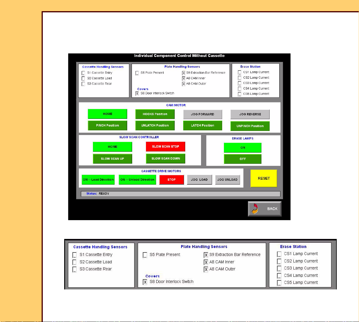
Individual Component Control
1 At the “Service System Diagnostic” screen, touch [Individual Component Control].
2 Touch [LATCH Position].
3 Check the status of the SENSORS.
Page 25
DIAGNOSTICS Using the Diagnostics
10DEC05
DG4825-1
Page
25 of 180
4 Does the status of the SENSORS match?
Yes No
Continue with Step 5. 1. Check the error logs. See Checking the Error Logs.
2. See the Error Codes to determine the possible cause
and action for the problem.
3. Continue with Step 5.
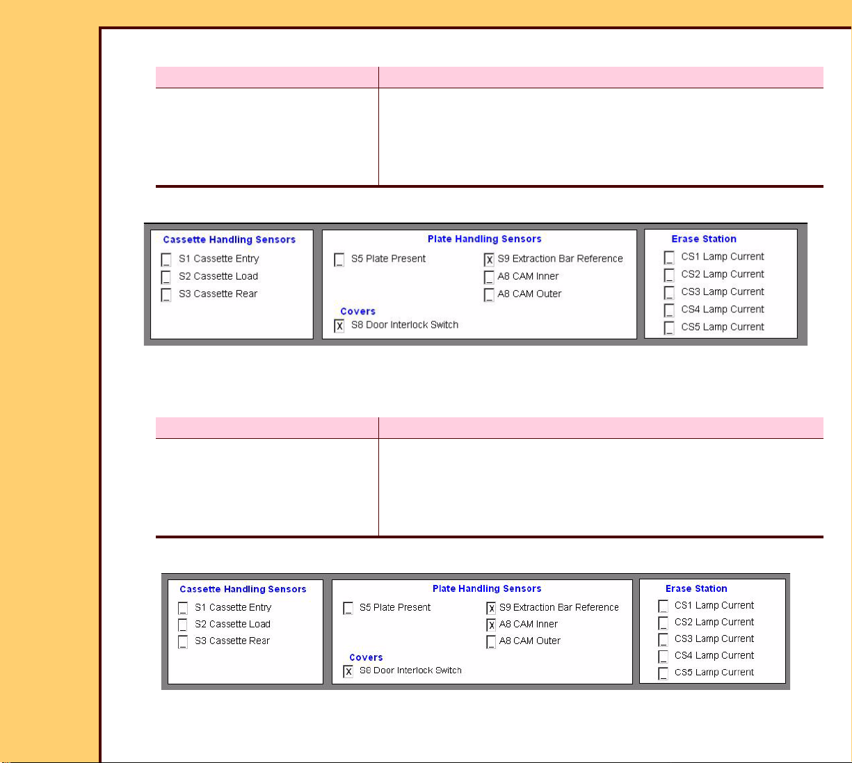
5 Touch [UNLATCH Position].
6 Check the status of the SENSORS.
7 Does the status of the SENSORS match?
Yes No
Continue with Step 8. 1. Check the error logs See Checking the Error Logs.
2. See the Error Codes to determine the possible cause
and action for the problem.
3. Continue with Step 8.
8 Touch [HOOKS Position].
9 Check the status of the SENSORS.
Page 26
DIAGNOSTICS Using the Diagnostics
10DEC05
DG4825-1
Page
26 of 180
10 Does the status of the SENSORS match?
Yes No
Continue with Step 11. 1. Check the error logs. See Checking the Error Logs.
2. See the Error Codes to determine the possible cause
and action for the problem.
3. Continue with Step 11.
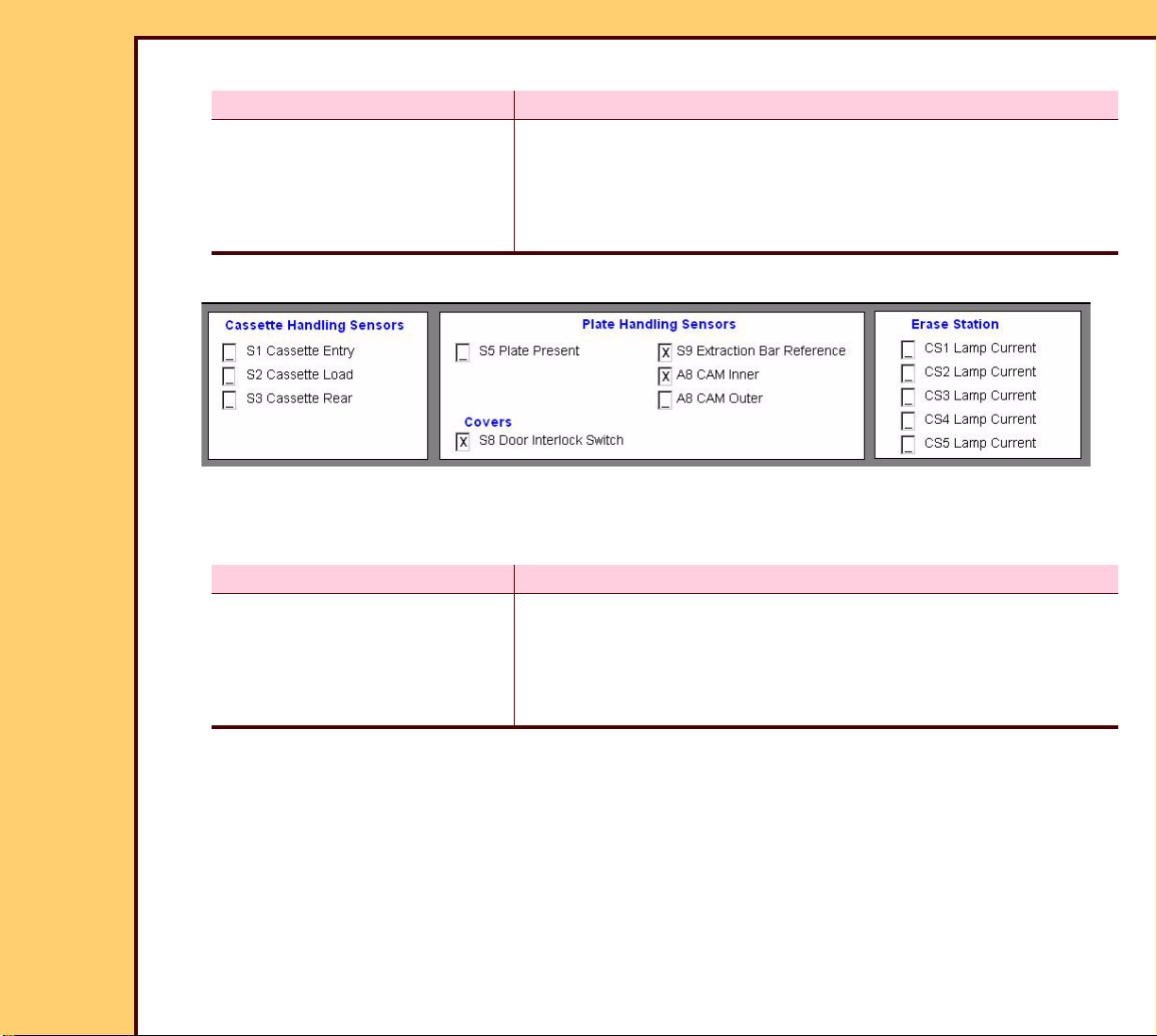
11 Touch [PINCH Position].
12 Check the status of the SENSORS.
13 Does the status of the SENSORS match?
Yes No
Continue with Step 14. 1. Check the error logs. See Checking the Error Logs.
2. See the Error Codes to determine the possible cause
and action for the problem.
3. Continue with Step 14.
Page 27
10DEC05
DG4825-1
Page
27 of 180
DIAGNOSTICS Using the Diagnostics
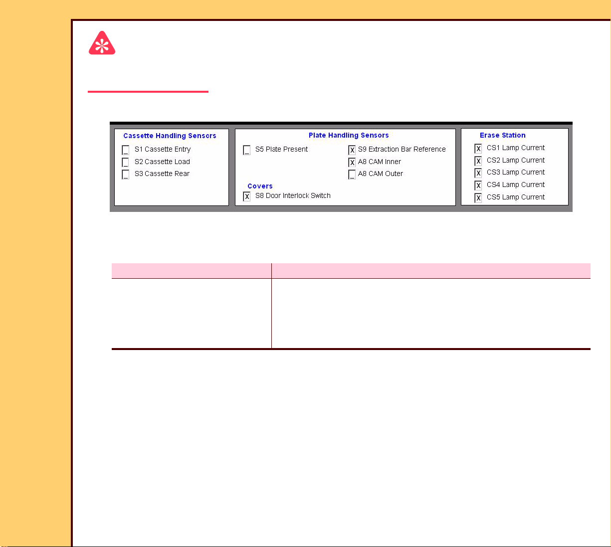
Important
The ERASE LAMPS energize for approximately 2 - 10 seconds. The marks display in the
“Erase Station” check boxes while the ERASE LAMPS are energized.
14 Touch [ERASE LAMPS ON].
15 Check the status of the SENSORS.
16 Does the status of the SENSORS match?
Yes No
Continue with the next test. 1. Check the error logs. See Checking the Error Logs.
2. See the Error Codes to determine the possible cause
and action for the problem.
3. Advance to the next test.
Page 28

DIAGNOSTICS Using the Diagnostics
10DEC05
DG4825-1
Page
28 of 180
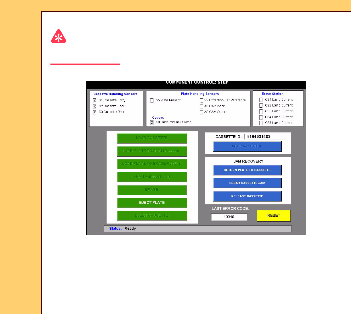
Component Control: Step
1 On the “System Service Diagnostic” screen, touch [Component Control: Step].
2 Insert the CASSETTE into the CR 825/850 SYSTEM.
3 Wait for the beep.
4 Touch [LOAD CASSETTE].
Page 29
10DEC05
DG4825-1
Page
29 of 180
DIAGNOSTICS Using the Diagnostics
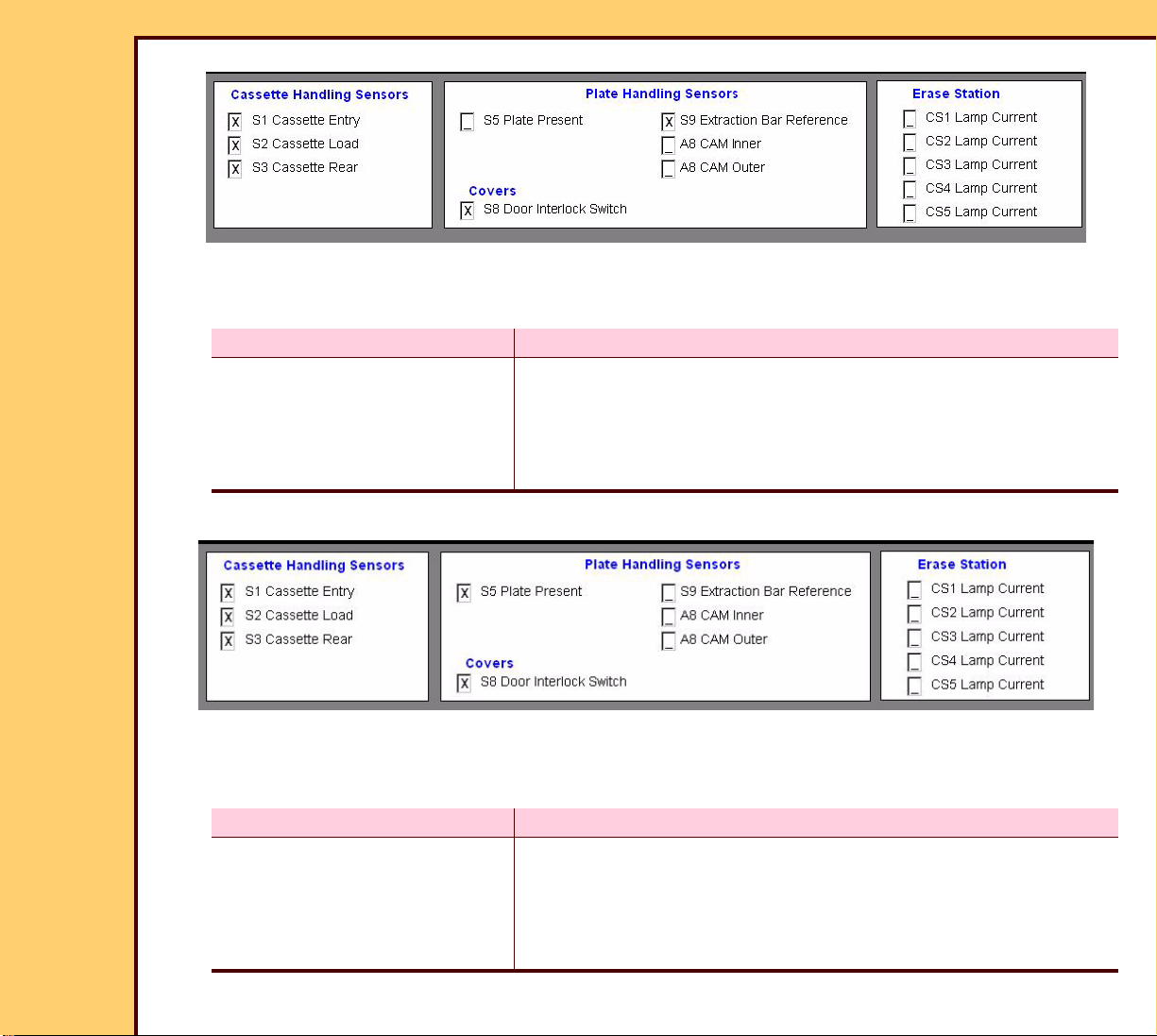
5 Check the status of the SENSORS.
6 Does the status of the SENSORS match?
Yes No
Continue with Step 7. 1. Check the error logs. See Checking the Error Logs.
2. See the Error Codes to determine the possible cause
and action for the problem.
3. Continue with Step 7.
7 Touch [LOAD PLATE TO SCAN Position].
8 Check the status of the SENSORS.
9 Does the status of the SENSORS match?
Yes No
Continue with Step 10. 1. Check the error logs. See Checking the Error Logs.
2. See the Error Codes to determine the possible cause
and action for the problem.
3. Continue with Step 10.
10 Touch [SCAN (without laser)].
Page 30
DIAGNOSTICS Using the Diagnostics
10DEC05
DG4825-1
Page
30 of 180
11 Wait for the test to complete.
Important
The ERASE LAMPS energize for approximately 2 - 10 seconds. The marks display in the
“Erase Station” check boxes while the ERASE LAMPS are energized.
12 Select [LOAD PLATE TO ERASE Position].
13 Check the status of the SENSORS.
Page 31

DIAGNOSTICS Using the Diagnostics
10DEC05
DG4825-1
Page
31 of 180
14 Does the status of the SENSORS match?
Yes No
Continue with Step 15. 1. Check the error logs. See Checking the Error Logs.
2. See the Error Codes to determine the possible cause
and action for the problem.
3. Continue with Step 15.
15 Touch [EJECT CASSETTE].
16 Remove the CASSETTE.
Light Test
1 On the “System Service Diagnostic” screen, touch [Light Test].
Page 32

DIAGNOSTICS Using the Diagnostics
10DEC05
DG4825-1
Page
32 of 180
2 Touch [TEST].
3 Wait for the test to complete.
4 Check that “PASS” displays in “AUTO-ZERO”.
5 Touch [START GRAPH].
6 Check that the value is approximately 4 - 5. Use:
• [ZOOM IN]
• [ZOOM OUT]
7 Touch [HV ON].
8 Check that the value increases.
Page 33

DIAGNOSTICS Using the Diagnostics
10DEC05
DG4825-1
Page
33 of 180
Slow Scan Current and Velocity Tests
1 On the “System Service Diagnostic” screen, touch [Slow Scan Current and Velocity
Tests].
2 Insert a 35 x 43 CASSETTE into the CR 825/850 SYSTEM.
3 Touch:
• [LOAD 35 x 43 CASSETTE]
• [START CURRENT TEST]
Page 34

DIAGNOSTICS Using the Diagnostics
10DEC05
DG4825-1
Page
34 of 180
4 Wait for the test to complete.
5 Check that the value is:
• 5 -180 between “Start of Scan” and “End of Scan”
• < 660 between “End of Scan” and “End of Travel”
• no spikes > 30
6 If the results are not correct, check the error logs. See Checking the Error Logs.
7 Touch [START VELOCITY TEST].
8 Wait for the test to complete.
9 Check that the results between “Start of Scan” and “End of Scan” are below 90 and
stable.
Page 35

DIAGNOSTICS Using the Diagnostics
10DEC05
DG4825-1
Page
35 of 180
10 If the results are not correct, check the error logs. See Checking the Error Logs.
11 Touch [EJECT THE CASSETTE].
12 Remove the CASSETTE.
Laser Power
1 On the “System Service Diagnostic” screen, touch [Laser Power].
2 Touch:
• [LASER ON]
• [READ]
Page 36

DIAGNOSTICS Using the Diagnostics
10DEC05
DG4825-1
Page
36 of 180
3 Check:
• “Laser Power” is 28 - 32 mW
• “Percent of original power” is ≥ 90%
4 Are the values correct?
Yes No
Continue with the next test. 1. Check the connections to the
LASER DIODE BOARD.
2. Install a new OPTICS
MODULE.
Galvo Test
1 On the “System Service Diagnostic” screen, touch [Galvo Test].
2 Touch:
• [START GALVO]
• [LASER ON]
Page 37

10DEC05
DG4825-1
Page
37 of 180
DIAGNOSTICS Using the Diagnostics
3 Open the TOP COVER.
TOP
COVER
4 Insert one sheet of paper into the CR
825/850 SYSTEM between:
• FOLD MIRROR
• COLLECTOR
CR 850
SYSTEM
5 Observe the laser beam on the sheet of
paper.
COLLECTOR
paper
laser beam
FOLD MIRROR
H194_1411GCA
H194_1411GC
Page 38

10DEC05
DG4825-1
Page
38 of 180
DIAGNOSTICS Using the Diagnostics
6 Touch [-100] until the “Set Amplitude” value is 400.
7 Observe the laser beam on the sheet of paper.
8 Touch [+100] until the “Set Amplitude” value is 3000.
9 Observe the laser beam on the sheet of paper.
“Set Amplitude” Laser Beam
400 short
3000 long
10 Does the laser beam change size correctly?
Yes No
Continue with the next
test.
Check the Error Codes for the cause of the
malfunction.
Page 39

DIAGNOSTICS Using the Diagnostics
10DEC05
DG4825-1
Page
39 of 180
PMT Test
1 On the “System Service Diagnostic” screen, touch [PMT Test].
2 Touch [START PMT TEST].
Page 40

DIAGNOSTICS Using the Diagnostics
10DEC05
DG4825-1
Page
40 of 180
3 Check that “PASSED” displays for both PMT 1 and PMT 2.
4 If one of the PMTs displays “FAILED”, install a new PMT. Use PMTs and COLLECTOR
AY.
5 If both PMTS display “FAILED”, check the connections between:
• PMT BOARD
• DAS BOARD
GALVO PLOT
Important
The “Galvo Plot” screen has more “Cassette Size” options with Software Version ≥ 4.1.
1 On the “System Service Diagnostic” screen, touch [GALVO PLOT].
2 Touch [START GALVO PLOT].
Page 41

10DEC05
DG4825-1
Page
41 of 180
DIAGNOSTICS Using the Diagnostics
3 Observe the GALVO PLOT.
Page 42

10DEC05
DG4825-1
Page
42 of 180
DIAGNOSTICS Using the Diagnostics
Normal GALVO PLOT
GALVO PLOT with low HOOK
GALVO PLOT with excessive HOOK
4 Check the values:
GALVO PLOT normal
AGC 10.0 V ± 0.1
2.5 vRef 2.5 ± 0.1
5 Are the values correct?
Yes No
Continue with the next test. Adjust the GALVO BOARD until the
GALVO PLOT is normal.
Page 43

DIAGNOSTICS Using the Diagnostics
10DEC05
DG4825-1
Page
43 of 180
Transport
1 On the “System Service Diagnostic” screen, touch [Transport].
2 Insert a CASSETTE into the CR 825/850 SYSTEM.
3 Touch either:
• [Cycle given number of times], or
• [Cycle continuously]
4 For the “Number of Cycles”, type: 10
Page 44

10DEC05
DG4825-1
Page
44 of 180
DIAGNOSTICS Using the Diagnostics
Action S1 S2 S3 S5 S8 S9
A8 CAM
Inner
A8 CAM
Outer
Loading CASSETTE X X X X
Loading PLATE X X X X X
Returning PLATE to CASSETTE X X X X X
Ejecting CASSETTE X X X X X X
5 Check that the SENSORS match the table during the correct action.
6 If the SENSORS do not match the table, check the error log. See Checking the Error
Logs.
7 See the Error Codes for the possible cause and action for the problem.
Page 45

DIAGNOSTICS Using the Diagnostics
10DEC05
DG4825-1
Page
45 of 180
AUTOLOOPER
1 On the “System Service Diagnostic” screen, touch [AutoLooper].
2 Insert a CASSETTE into the CR 825/850 SYSTEM.
3 Touch either:
• [Scan given number of times], or
• [Scan Continuously]
4 For the “Number of Cycles”, type: 10
Page 46

10DEC05
DG4825-1
Page
46 of 180
DIAGNOSTICS Using the Diagnostics
Action S1 S2 S3 S5 S8 S9
A8 CAM
Inner
A8 CAM
Outer
CS1 CS2 CS3 CS4 CS5
Load CASSETTE X X X X
Load PLATE X X X X X
Erase CASSETTE X X XXXXX
Return PLATE to
XXX XX
CASSETTE
Ejects CASSETTE X X X X X X
5 Check that the SENSORS match the table for the correct action.
6 If the SENSORS do not match the table, see the error log. See Checking the Error
Logs.
7 See the Error Codes for the possible cause and action for the problem.
Page 47

DIAGNOSTICS Using the Diagnostics
10DEC05
DG4825-1
Page
47 of 180
MCPU Self Test
1 On the “System Service Diagnostic” screen, touch [System Self Test].
2 Touch [START MCPU SELF TEST].
3 Wait approximately 20 seconds for the test to complete.
Page 48

10DEC05
DG4825-1
Page
48 of 180
DIAGNOSTICS Using the Diagnostics
4 Observe the results for each test.
5 If any of the tests display “FAILED”, check the error logs. See Checking the Error Logs.
6 See the Error Codes to determine the possible cause and action for the problem.
Page 49

10DEC05
DG4825-1
Page
49 of 180
DIAGNOSTICS Using the Diagnostics
Diagnostic Procedures
Checking the Error Logs
1 On the “System Service Diagnostic” screen, touch [Error Log].
2 Touch either:
• [Sort By Date],
• [Sort By Error Code], or
• [Sort By Cassette ID]
Page 50

DIAGNOSTICS Using the Diagnostics
10DEC05
DG4825-1
Page
50 of 180
Checking the Error Frequency Log
1 On the “System Service Diagnostic” screen, touch [Error Frequency Log].
2 Touch either:
• [Sort By Date],
• [Sort By Error Code], or
• [Sort Error Frequency]
Page 51

DIAGNOSTICS Using the Diagnostics
10DEC05
DG4825-1
Page
51 of 180
Checking the Actuation Logs
1 On the “System Service Diagnostic” screen, touch [Actuation Log].
Page 52

DIAGNOSTICS Using the Diagnostics
10DEC05
DG4825-1
Page
52 of 180
Storing the Error Logs on a Disk
1 On the “System Service Diagnostic” screen, touch [Expor t Log Files].
2 Insert a disk into the DRIVE.
3 Touch either:
• [COPY ERROR LOGS TO FLOPPY],
• [COPY ACTUATION LOGS TO FLOPPY], or
• [COPY SLOWSCAN PARAMETERS FILE TO FLOPPY]
Page 53

DIAGNOSTICS Using the Diagnostics
10DEC05
DG4825-1
Page
53 of 180
Clearing the Error Logs
1 On the “System Service Diagnostic” screen, touch [Clear Error Log].
2 Touch [CLEAR ERROR LOG].
Page 54

DIAGNOSTICS Using the Diagnostics
10DEC05
DG4825-1
Page
54 of 180
Installing Files from a Disk
1 On the “System Service Diagnostic” screen, touch [Import Files].
2 Insert the disk into the DRIV E.
3 To install the ACTUATION LOGS to the CR 825/850 SYSTEM, touch [COPY ACTUATION
LOGS FROM FLOPPY].
4 To install the parameters of the SLOW SCAN, touch:
• [GET SLOWSCAN HOME POSITION FROM FLOPPY]
• [UPDATE SLOWSCAN PARAMETER FILE FROM FLOPPY]
Page 55

DIAGNOSTICS Using the Diagnostics
10DEC05
DG4825-1
Page
55 of 180
Displaying the Software Versions
Important
The graphic is an example. Your display might not be the same.
1 On the “System Service Diagnostic” screen, touch [Display Software Versions].
Page 56

DIAGNOSTICS Using the Diagnostics
10DEC05
DG4825-1
Page
56 of 180
Downloading Software to the BOARDS
1 On the “System Service Diagnostic” screen, touch [Download to Circuit Boards].
2 Touch either:
• [DOWNLOAD MCPU APPLICATION],
• [DOWNLOAD MSC APPLICATION],
• [DOWNLOAD BOOT AND APPLICATIONS],
• [DOWNLOAD APPLICATIONS], or
• [DOWNLOAD PARAMETERS]
Page 57

10DEC05
DG4825-1
Page
57 of 180
DIAGNOSTICS Error Codes
Section 2: Error Codes
Overview
The first 2 digits of the error code identify the subsystem or component with the error.
Example: 11009
The first 2 digits, 11, indicate that the error occurred in the subsystem LATCH/UNLATCH
CAM.
1 Use Table 8 to help identify the component with the error.
2 Advance to the error code to diagnose the error.
Table 8 Subsystem
ID Subsystem
10 CASSETTE LOAD
11 LATCH/UNLATCH CAM
12 SLOW SCAN AY
13 ERASE LAMPS
14 POWER SUPPLY
15 DATA PAT H
16 Calibration
19 “Self Test” for the MASTER CENTRAL PROCESSING UNIT
22 MOTION SYSTEM CONTRO L BOARD
29 MOTION SYSTEM CONTRO L BOARD RTXC
30 MOTION SYSTEM CONTROL BOARD SYSTEM
32 Communications for the MOTION SYSTEM CONTROL BOARD
Windows 2000 Subsystem
47 Shutdown Management
49 DISK MANAGER
55 Installation
Page 58

10DEC05
DG4825-1
Page
58 of 180
DIAGNOSTICS Error Codes
CASSETTE LOAD
10006 - CASSETTE REAR SENSOR S3 did not detect CASSETTE
Description: A timeout occurred because the CASSETTE REAR SENSOR S3 did not
detect the CASSETTE when expected.
Cause 1: The CASSETTE REAR SENSOR S3 operates correctly, but another malfunction
occurred.
Action: Check:
• DRIVE ROLLERS rotate freely
• CASSETTE REAR SENSOR S3 for obstructions
• adjustment of the SLED CAM FOLLOWER
Cause 2: The CASSETTE REAR SENSOR S3 malfunctioned.
Action: Check:
• status of the CASSETTE REAR SENSOR S3 - use Individual Component
Control
• LED DS22 on the MOTION SYSTEM CONTROL BOARD A1 changes status
• power to the CASSETTE REAR SENSOR S3
• condition of the CASSETTE REAR SENSOR S3
10007 - CASSETTE REAR SENSOR S3 did not detect loading of CASSETTE
Cause 1: The CASSETTE REAR SENSOR S3 operates correctly, but another malfunction
occurred.
Action: Check:
• DRIVE ROLLERS rotate freely
• CASSETTE REAR SENSOR S3 for obstructions
• adjustment of the SLED CAM FOLLOWER
Page 59

10DEC05
DG4825-1
Page
59 of 180
DIAGNOSTICS Error Codes
Cause 2: The CASSETTE REAR SENSOR S3 malfunctioned.
Action: Check:
• status of CASSETTE REAR SENSOR S3 - use Individual Component
Control
• LED DS22 on the MOTION SYSTEM CONTROL BOARD A1 changes status
• power to the CASSETTE REAR SENSOR S3
• condition of the CASSETTE REAR SENSOR S3
10008 - CASSETTE REAR SENSOR S3 did not clear
Cause 1: The CASSETTE REAR SENSOR S3 operates correctly, but another malfunction
occurred.
Action: Check:
• DRIVE ROLLERS rotate freely
• CASSETTE REAR SENSOR S3 for obstructions
• adjustment of the SLED CAM FOLLOWER
Cause 2: The CASSETTE REAR SENSOR S3 malfunctioned.
Action: Check:
• status of the CASSETTE REAR SENSOR S3 - use Individual Component
Control
• LED DS22 on the MOTION SYSTEM CONTROL BOARD A1 changes status
• power to the CASSETTE REAR SENSOR S3
• condition of the CASSETTE REAR SENSOR S3
Page 60

DIAGNOSTICS Error Codes
10DEC05
DG4825-1
Page
60 of 180
10009 - CASSETTE LOAD SENSOR S2 did not clear
Cause 1: The CASSETTE LOAD SENSOR S2 operates correctly, but an obstruction
occurred.
Action: Check:
• DRIVE ROLLERS rotate freely
• CASSETTE LOAD SENSOR S2 for obstructions
• adjustment of the SLED CAM FOLLOWER
Cause 2: The CASSETTE LOAD SENSOR S2 malfunctioned.
Action: Check:
• status of the CASSETTE LOAD SENSOR S2 - use Individual Component
Control
• LED DS21 on the MOTION SYSTEM CONTROL BOARD A1 changes status
• power to the CASSETTE LOAD SENSOR S2
• condition of the EMITTER and DETECTOR of the CASSETTE LOAD SENSOR
S2
Page 61

10DEC05
DG4825-1
Page
61 of 180
DIAGNOSTICS Error Codes
10014 - CASSETTE REAR SENSOR S3 blocked on load
Description: The CASSETTE REAR SENSOR S3 is blocked before a CASSETTE is
loaded.
Cause 1: The CASSETTE REAR SENSOR S3 malfunctioned.
Action: Check:
• status of the CASSETTE REAR SENSOR S3 - use Individual Component
Control
• LED DS22 on the MOTION SYSTEM CONTROL BOARD A1 changes status
• power to the CASSETTE REAR SENSOR S3
• condition of the CASSETTE REAR SENSOR S3
10016 - Load CASSETTE: Retry attempt
Description: The CASSETTE REAR SENSOR S3 did not detect the CASSETTE. The
DRIVE ROLLERS actuate 3 times to load the CASSETTE indicating this
error each time.
Cause 1: The CASSETTE REAR SENSOR S3 operates correctly, but another malfunction
occurred.
Action: Check:
• DRIVE ROLLERS rotate freely
• CASSETTE REAR SENSOR S3 for obstructions
• adjustment of the SLED CAM FOLLOWER
Cause 2: The CASSETTE REAR SENSOR S3 malfunctioned.
Action: Check:
• status of the CASSETTE REAR SENSOR S3 - use Individual Component
Control
• LED DS22 on the MOTION SYSTEM CONTROL BOARD A1 changes status
• power to the CASSETTE REAR SENSOR S3
• condition of the CASSETTE REAR SENSOR S3
Page 62

10DEC05
DG4825-1
Page
62 of 180
DIAGNOSTICS Error Codes
10017 - Eject CASSETTE: Retry attempt
Description: The CASSETTE LOAD SENSOR S2 did not clear when the DRIVE
ROLLERS started to eject the CASSETTE.
Cause 1: The CASSETTE LOAD SENSOR S2 operates correctly, but an obstruction
occurred.
Action: Check:
• DRIVE ROLLERS rotate freely
• CASSETTE LOAD SENSOR S2 for obstructions
• adjustment of the SLED CAM FOLLOWER
Cause 2: The CASSETTE LOAD SENSOR S2 malfunctioned.
Action: Check:
• status of the CASSETTE LOAD SENSOR S2 - use Individual Component
Control
• LED DS21 on the MOTION SYSTEM CONTROL BOARD A1 changes status
• power to the CASSETTE LOAD SENSOR S2
• condition of the EMITTER and DETECTOR of the CASSETTE LOAD SENSOR
S2
10019 - Eject CASSETTE: Timeout error
Description: The CASSETTE LOAD SENSOR S2 did not clear in the correct time
when the DRIVER ROLLERS ejected the CASSETTE
Cause 1: The CASSETTE LOAD SENSOR S2 operates correctly, but an obstruction
occurred.
Action: Check:
• DRIVE ROLLERS rotate freely
• CASSETTE LOAD SENSOR S2 for obstructions
• adjustment of the SLED CAM FOLLOWER
Page 63

10DEC05
DG4825-1
Page
63 of 180
DIAGNOSTICS Error Codes
Cause 2: The CASSETTE LOAD SENSOR S2 malfunctioned.
Action: Check:
• status of the CASSETTE LOAD SENSOR S2 - use Individual Component
Control
• LED DS21 on the MOTION SYSTEM CONTROL BOARD A1 changes status
• power to the CASSETTE LOAD SENSOR S2
• condition of the EMITTER and DETECTOR of the CASSETTE LOAD SENSOR
S2
10020 - Malfunction at CASSETTE ENTRY SENSOR S1
Description: The CASSETTE ENTRY SENSOR S1 is blocked when it should be clear.
Cause 1: The CASSETTE ENTRY SENSOR S1 malfunctioned.
Action: Check:
• status of the CASSETTE ENTRY SENSOR S1 - use Individual Component
Control
• LED DS19 on the MOTION SYSTEM CONTROL BOARD A1 changes status
• power to the CASSETTE ENTRY SENSOR S1
• condition of the EMITTER and DETECTOR of the CASSETTE ENTRY
SENSOR S1
10021 - MSC BOARD A1: Software malfunction
Description: The DRIVE ROLLER received a command that was not correct.
Cause 1: The software for the MOTION SYSTEM CONTROL BOARD A1 malfunctioned.
Action: Install the software again for the MOTION SYSTEM CONTROL BOARD A1.
Cause 2: The MOTION SYSTEM CONTROL BOARD A1 malfunctioned.
Action: Do the checkout for the MOTION SYSTEM CONTROL BOARD A1.
Page 64

DIAGNOSTICS Error Codes
10DEC05
DG4825-1
Page
64 of 180
10022 - MSC BOARD A1: Software malfunction
Description: The DRIVE ROLLER received a signal when waiting for an interr upt or
timeout to occur.
Cause 1: The software for the MOTION SYSTEM CONTROL BOARD A1 malfunctioned.
Action: Install the software again for the MOTION SYSTEM CONTROL BOARD A1.
Cause 2: The MOTION SYSTEM CONTROL BOARD A1 malfunctioned.
Action: Do the checkout for the MOTION SYSTEM CONTROL BOARD A1.
10024 - MSC BOARD A1: Software malfunction
Description: A timeout occurred setting up the motion for the DRIVE ROLLER.
Cause 1: The software for the MOTION SYSTEM CONTROL BOARD A1 malfunctioned.
Action: Install the software again for the MOTION SYSTEM CONTROL BOARD A1.
Cause 2: The MOTION SYSTEM CONTROL BOARD A1 malfunctioned.
Action: Do the checkout for the MOTION SYSTEM CONTROL BOARD A1.
10029 - READER detected the CASSETTE BAR CODE label as backward
Cause 1: The CASSETTE was inserted backward into the CR 825/850 SYSTEM.
Action: Insert the CASSETTE correctly.
Cause 2: The BAR CODE LABEL is installed backward on the CASSETTE.
Action: 1. Remove the BAR CODE LABEL.
2. Install a new BAR CODE LABEL.
10030 - READER did not read the CASSETTE BAR CODE
Cause 1: The CASSETTE:
• has a bar code that you cannot read
• does not have a bar code
Action: Install the correct bar code.
Page 65

10DEC05
DG4825-1
Page
65 of 180
DIAGNOSTICS Error Codes
Cause 2: The internal BAR CODE READER malfunctioned.
Action: 1. Check:
• alignment of the BAR CODE READER
• BAR CODE READER is not blocked
• connections to the BAR CODE READER
2. If the BAR CODE READER emits a beep when you insert a CASSETTE, but
the CASSETTE does not load, check the CONNECTOR RJ45 between the
BAR CODE READER and the MASTER CENTRAL PROCESSING UNIT
BOARD A2.
3. If the BAR CODE READER does not emit a beep when you load a
CASSETTE, check the CONNECTOR RJ45 between the BAR CODE READER
and the MOTION SYSTEM CONTROL BOARD A1.
Page 66

10DEC05
DG4825-1
Page
66 of 180
DIAGNOSTICS Error Codes
LATCH/UNLATCH CAM
11001 - DUPLEX CAM did not move to Home Position
Cause: The DUPLEX CAM malfunctioned.
Action: Do the checkout for the CASSETTE HANDLING AY.
11002 - DUPLEX CAM did not move to “PINCH” position
Cause: The DUPLEX CAM malfunctioned.
Action: Do the checkout for the CASSETTE HANDLING AY.
11003 - DUPLEX CAM did not move to “CLAMP/UNLATCH” position
Cause: The DUPLEX CAM malfunctioned.
Action: Do the checkout for the CASSETTE HANDLING AY.
11004 - DUPLEX CAM did not move to “UNCLAMP/LATCH” position
Cause: The DUPLEX CAM malfunctioned.
Action: Do the checkout for the CASSETTE HANDLING AY.
11005 - DUPLEX CAM did not move to “UNPINCH” position
Cause: The DUPLEX CAM malfunctioned.
Action: Do the checkout for the CASSETTE HANDLING AY.
11006 - CAM OUTER SENSOR S11 did not detect position of DUPLEX CAM
Cause: The DUPLEX CAM malfunctioned.
Action: Do the checkout for the CASSETTE HANDLING AY.
11007 - CAM INNER SENSOR S10 did not detect Home Position for DUPLEX CAM
Cause: The DUPLEX CAM malfunctioned.
Action: Do the checkout for the CASSETTE HANDLING AY.
Page 67

10DEC05
DG4825-1
Page
67 of 180
DIAGNOSTICS Error Codes
11009 - DUPLEX CAM: Move failed
Cause: The DUPLEX CAM malfunctioned.
Action: Do the checkout for the CASSETTE HANDLING AY.
11010 - DUPLEX CAM: Software command failed on the MSC BD
Description: The DUPLEX CAM received a command to move that was not correct.
Cause 1: The DUPLEX CAM malfunctioned.
Action: Do the checkout for the CASSETTE HANDLING AY.
Cause 2: The MOTION SYSTEM CONTROL BOARD A1 malfunctioned.
Action: Do the checkout for the MOTION SYSTEM CONTROL BOARD A1.
11014 - DUPLEX CAM: Timeout Error
Description: The DUPLEX CAM did not move in the time allowed.
Cause: The DUPLEX CAM malfunctioned.
Action: Do the checkout for the CASSETTE HANDLING AY.
11015 - Move command failed because SLOW SCAN not at Home Position
Cause 1: The DUPLEX CAM malfunctioned.
Action: Do the checkout for the CASSETTE HANDLING AY.
Cause 2: The SLOW SCAN CONTROLLER BOARD A6 malfunctioned.
Action: Do the checkout for the SLOW SCAN CONTROLLER BOARD A6 and COIL
BOARD A7.
11016 - MSC BOARD A1: Software Error for DUPLEX CAM
Description: The MOTION SYSTEM CONTROL BOARD A1 did not provide the RTXC
TIMER. This TIMER determines the timeouts for the motion of the
DUPLEX CAM.
Page 68

10DEC05
DG4825-1
Page
68 of 180
DIAGNOSTICS Error Codes
Cause: The MOTION SYSTEM CONTROL BOARD A1 malfunctioned.
Action: Do the checkout for the MOTION SYSTEM CONTROL BOARD A1.
11017 - MSC BOARD A1: Software Error for DUPLEX CAM
Description: The MOTION SYSTEM CONTROL BOARD A1 did not set up the
command to move for the DUPLEX CAM.
Cause: The MOTION SYSTEM CONTROL BOARD A1 malfunctioned.
Action: Do the checkout for the MOTION SYSTEM CONTROL BOARD A1.
11018 - DUPLEX CAM did not move to next position
Cause: The DUPLEX CAM malfunctioned.
Action: Do the checkout for the CASSETTE HANDLING AY.
11019 - DUPLEX CAM did not move to “PINCH” position
Cause 1: The DUPLEX CAM malfunctioned.
Action: Do the checkout for the CASSETTE HANDLING AY.
Cause 2: The SLOW SCAN CONTROLLER BOARD A6 malfunctioned.
Action: Do the checkout for the SLOW SCAN CONTROLLER BOARD A6 and COIL
BOARD A7.
11020 - DUPLEX CAM did not move to “UNLATCH” position
Cause 1: The MOTION SYSTEM CONTROL BOARD A1 malfunctioned.
Action: Do the checkout for the MOTION SYSTEM CONTROL BOARD A1.
Cause 2: The DUPLEX CAM malfunctioned.
Action: Do the checkout for the CASSETTE HANDLING AY.
Page 69

DIAGNOSTICS Error Codes
10DEC05
DG4825-1
Page
69 of 180
11021 - DUPLEX CAM did not move to “LATCH” position
Cause 1: The MOTION SYSTEM CONTROL BOARD A1 malfunctioned.
Action: Do the checkout for the MOTION SYSTEM CONTROL BOARD A1.
Cause 2: The DUPLEX CAM malfunctioned.
Action: Do the checkout for the CASSETTE HANDLING AY.
11022 - DUPLEX CAM did not move to “UNPINCH” position
Cause 1: The DUPLEX CAM malfunctioned.
Action: Do the checkout for the CASSETTE HANDLING AY.
Cause 2: The MOTION SYSTEM CONTROL BOARD A1 malfunctioned.
Action: Do the checkout for the MOTION SYSTEM CONTROL BOARD A1.
SLOW SCAN AY
12001 - SLOW SCAN EXTRACTION BAR did not move to Home Position
Cause 1: The EXTRACTION BAR malfunctioned.
Action: 1. Remove any obstructions in the path of the EXTRACTION BAR.
2. Check the SLOW SCAN MOTOR.
3. Do the checkout for the SLOW SCAN CONTROLLER BOARD A6 a nd COIL
BOARD A7.
4. Check the EXTRACTION BAR HOME POSITION
Cause 2: The EXTRACTION BAR SENSOR S9 malfunctioned.
Action: Do the checkout for the EXTRACTION BAR SENSOR S9.
Page 70

10DEC05
DG4825-1
Page
70 of 180
DIAGNOSTICS Error Codes
12002 - EXTRACTION BAR REFERENCE SENSOR S9 failed to activate
Cause 1: The EXTRACTION BAR SENSOR S9 operates correctly, but another malfunction
occurred.
Action: 1. Remove any obstructions from the path of the EXTRAC TION BAR.
2. Do the checkout for the SLOW SCAN CONTROLLER BOARD A6 a nd COIL
BOARD A7.
Cause 2: The EXTRACTION BAR SENSOR S9 malfunctioned.
Action: Do the checkout for the EXTRACTION BAR SENSOR S9.
12003 - PLATE PRESENT SENSOR S5 did not detect PLATE
Cause 1: The PLATE PRESENT SENSOR S5 operates correctly, but another malfunction
occurred.
Action: 1. Check:
• PLATE was removed from the CASSETTE
• SLOW SCAN MOTOR operates correctly
2. Do the checkout for the SLOW SCAN CONTROLLER BOARD A6 a nd COIL
BOARD A7.
3. Remove any obstructions from the path of the EXTRAC TION BAR.
Cause 2: The PLATE PRESENT SENSOR S5 malfunctioned.
Action: Do the checkout PLATE PRESENT SENSOR S5.
Page 71

10DEC05
DG4825-1
Page
71 of 180
DIAGNOSTICS Error Codes
12004 - PLATE PRESENT SENSOR S5 failed to activate
Cause 1: The PLATE PRESENT SENSOR S5 operates correctly, but another malfunction
occurred.
Action: 1. Check:
• PLATE was removed from the CASSETTE
• SLOW SCAN MOTOR operates correctly
2. Do the checkout for the SLOW SCAN CONTROLLER BOARD A6 a nd COIL
BOARD A7.
3. Remove any obstructions from the path of the EXTRAC TION BAR.
Cause 2: The PLATE PRESENT SENSOR S5 malfunctioned.
Action: Do the checkout PLATE PRESENT SENSOR S5.
Cause 3: The MOTION SYSTEM CONTROL BOARD A1 malfunctioned.
Action: Do the checkout for the MOTION SYSTEM CONTROL BOARD A1.
12009 - Caution! SLOW SCAN MOTOR drawing too much power
Cause: A malfunction occurred in one or more of the following components:
• COIL BOARD
• EXTRACTION BAR SENSOR S9
• SLOW SCAN AY
Action: 1. Check for an obstruction.
2. Do the checkout for the SLOW SCAN CONTROLLER BOARD A6 a nd COIL
BOARD A7.
Page 72

10DEC05
DG4825-1
Page
72 of 180
DIAGNOSTICS Error Codes
12012 - SLOW SCAN AY: Timeout Error
Description: The PLATE did not move within the correct time.
Cause: A malfunction occurred in one or more of the following components:
• COIL BOARD
• SLOW SCAN AY
Action: 1. Check for an obstruction.
2. Do the checkout for the SLOW SCAN CONTROLLER BOARD A6 a nd COIL
BOARD A7.
12013 - SLOW SCAN AY: Timeout error
Description: A command for the PLATE that is not correct was made by the system
software.
Cause: The MOTION SYSTEM CONTROL BOARD A1 malfunctioned.
Action: Do the checkout for the MOTION SYSTEM CONTROL BOARD A1.
12014 - MSC BOARD A1: Software Error for SLOW SCAN
Description: This error might occur during the diagnostics if the service person star ts
to move the PLATE before the PLATE stops moving.
Cause: The SLOW SCAN AY malfunctioned.
Action: Do the checkout for the SLOW SCAN CONTROLLER BOARD A6 and COIL
BOARD A7.
12100 - SLOW SCAN CONTROLLER BOARD A6: Software Error
Description: The SLOW SCAN AY will not move.
Cause: The SLOW SCAN CONTROLLER BOARD A6 malfunctioned.
Action: 1. Energize and de-energize the CR 825/850 SYSTEM.
2. Do the checkout for the SLOW SCAN CONTROLLER BOARD A6 a nd COIL
BOARD A7.
Page 73

10DEC05
DG4825-1
Page
73 of 180
DIAGNOSTICS Error Codes
12101 - SLOW SCAN a velocity malfunction during scan
Description: The SLOW SCAN AY exceeded the speed limit when moving the SCAN
PLATE.
Cause 1: The speed of the SLOW SCAN AY exceeded the limit. A band might appear on
the image.
Action: Do the Slow Scan Current and Velocity Tests.
Cause 2: The SLOW SCAN CONTROLLER BOARD A6 malfunctioned.
Action: Do the checkout for the SLOW SCAN CONTROLLER BOARD A6 and COIL
BOARD A7.
12102 - SLOW SCAN stopped during scan
Cause: The SLOW SCAN CONTROLLER BOARD A6 malfunctioned.
Action: 1. Check for an obstruction.
2. Do the checkout for the SLOW SCAN CONTROLLER BOARD A6 a nd COIL
BOARD A7.
12103 - SLOW SCAN stopped during scan
Cause: The SLOW SCAN CONTROLLER BOARD A6 malfunctioned.
Action: 1. Check for an obstruction.
2. Do the checkout for the SLOW SCAN CONTROLLER BOARD A6 a nd COIL
BOARD A7.
12104 - SLOW SCAN: Timeout while moving to SENSOR S9
Description: The SLOW SCAN AY did not reach the EXTRACTION BAR SENSOR
S9.
Cause: The SLOW SCAN CONTROLLER BOARD A6 malfunctioned.
Action: Do the checkout for the SLOW SCAN CONTROLLER BOARD A6 and COIL
BOARD A7.
Page 74

10DEC05
DG4825-1
Page
74 of 180
DIAGNOSTICS Error Codes
12107 - SLOW SCAN: +24 V DC malfunction during scan
Cause 1: The POWER SUPPLY PS1 malfunctioned.
Action: Do the checkout for the POWER SUPPLY PS1.
Cause 2: The SLOW SCAN CONTROLLER BOARD A6 malfunctioned.
Action: Do the checkout for the SLOW SCAN CONTROLLER BOARD A6 and COIL
BOARD A7.
12108 - SLOW SCAN stopped during scan
Cause: The SLOW SCAN CONTROLLER BOARD A6 malfunctioned.
Action: Do the checkout for the SLOW SCAN CONTROLLER BOARD A6 and COIL
BOARD A7.
12109 - SLOW SCAN stopped during scan
Cause: The SLOW SCAN CONTROLLER BOARD A6 malfunctioned.
Action: Do the checkout for the SLOW SCAN CONTROLLER BOARD A6 and COIL
BOARD A7.
12110 - SLOW SCAN did not communicate with the MOTION SYSTEM CONTROL
Description: The SLOW SCAN AY did not move because of a communication error
with the SLOW SCAN CONTROLLER BOARD A6.
Cause: The SLOW SCAN CONTROLLER BOARD A6 malfunctioned.
Action: Do the checkout for the SLOW SCAN CONTROLLER BOARD A6 and COIL
BOARD A7.
12111 - SLOW SCAN did not move
Cause: The SLOW SCAN CONTROLLER BOARD A6 malfunctioned.
Action: Do the checkout for the SLOW SCAN CONTROLLER BOARD A6 and COIL
BOARD A7.
Page 75

10DEC05
DG4825-1
Page
75 of 180
DIAGNOSTICS Error Codes
12112 - SLOW SCAN did not move
Cause: The SLOW SCAN CONTROLLER BOARD A6 malfunctioned.
Action: Do the checkout for the SLOW SCAN CONTROLLER BOARD A6 and COIL
BOARD A7.
12113 - SLOW SCAN CONTROLLER BOARD A6: NVRAM malfunctioned
Cause: The SLOW SCAN CONTROLLER BOARD A6 malfunctioned.
Action: Do the checkout for the SLOW SCAN CONTROLLER BOARD A6 and COIL
BOARD A7.
12115 - SLOW SCAN CONTROLLER BOARD A6: Software Error
Cause 1: The SLOW SCAN CONTROLLER BOARD A6 malfunctioned.
Action: Do the checkout for the SLOW SCAN CONTROLLER BOARD A6 and COIL
BOARD A7.
Cause 2: The MOTION SYSTEM CONTROL BOARD A1 malfunctioned.
Action: Do the checkout for the MOTION SYSTEM CONTROL BOARD A1.
12116 - SLOW SCAN CONTROLLER BOARD A6 did not communicate with MSC
Description: The SLOW SCAN AY did not stop moving before the next command to
move. This error indicates a communication error with the SLOW SCAN
CONTROLLER BOARD A6.
Cause 1: The SLOW SCAN CONTROLLER BOARD A6 malfunctioned.
Action: Do the checkout for the SLOW SCAN CONTROLLER BOARD A6 and COIL
BOARD A7.
Cause 2: The MOTION SYSTEM CONTROL BOARD A1 malfunctioned.
Action: Do the checkout for the MOTION SYSTEM CONTROL BOARD A1.
Page 76

10DEC05
DG4825-1
Page
76 of 180
DIAGNOSTICS Error Codes
12120 - SLOW SCAN did not move
Cause: The SLOW SCAN CONTROLLER BOARD A6 malfunctioned.
Action: Do the checkout for the SLOW SCAN CONTROLLER BOARD A6 and COIL
BOARD A7.
12121 - SLOW SCAN did not move
Cause: The SLOW SCAN CONTROLLER BOARD A6 malfunctioned.
Action: Do the checkout for the SLOW SCAN CONTROLLER BOARD A6 and COIL
BOARD A7.
12122 - SLOW SCAN COIL BOARD A7 malfunctioned
Description: The SLOW SCAN AY stopped or did not move at all.
Cause: The SLOW SCAN CONTROLLER BOARD A6 malfunctioned.
Action: Do the checkout for the SLOW SCAN CONTROLLER BOARD A6 and COIL
BOARD A7.
12123 - SLOW SCAN CONTROLLER BOARD A6: Software Error
Description: The MOTOR CONTROLLER for the SLOW SCAN AY malfunctioned.
Cause: The SLOW SCAN CONTROLLER BOARD A6 malfunctioned.
Action: Do the checkout for the SLOW SCAN CONTROLLER BOARD A6 and COIL
BOARD A7.
12124 - SLOW SCAN CONTROLLER BOARD A6: Software Error
Description: An error occurred when initializing the SLOW SCAN AY.
Cause: The SLOW SCAN CONTROLLER BOARD A6 malfunctioned.
Action: Do the checkout for the SLOW SCAN CONTROLLER BOARD A6 and COIL
BOARD A7.
Page 77

10DEC05
DG4825-1
Page
77 of 180
DIAGNOSTICS Error Codes
12125 - SLOW SCAN COIL BOARD A7 malfunctioned
Description: The SLOW SCAN AY stopped or did not move at all.
Cause: The SLOW SCAN CONTROLLER BOARD A6 malfunctioned.
Action: Do the checkout for the SLOW SCAN CONTROLLER BOARD A6 and COIL
BOARD A7.
12126 - Caution! SLOW SCAN MOTOR is overheated
Description: The SLOW SCAN MOTOR was using excessive power and is too hot.
Cause: Malfunction in one or more of the following:
• COIL BOARD A7
• EXTRACTION BAR SENSOR S9
• SLOW SCAN AY
Action: 1. Check for an obstruction.
2. Do the checkout for the SLOW SCAN CONTROLLER BOARD A6 a nd COIL
BOARD A7.
12130 - SLOW SCAN CONTROLLER BOARD A6: Software Error
Cause: The SLOW SCAN CONTROLLER BOARD A6 malfunctioned.
Action: Do the checkout for the SLOW SCAN CONTROLLER BOARD A6 and COIL
BOARD A7.
12131 - SLOW SCAN CONTROLLER BOARD A6 did not communicate with MSC
Cause 1: The SLOW SCAN CONTROLLER BOARD A6 malfunctioned.
Action: Do the checkout for the SLOW SCAN CONTROLLER BOARD A6 and COIL
BOARD A7.
Cause 2: The MOTION SYSTEM CONTROL BOARD A1 malfunctioned.
Action: Do the checkout for the MOTION SYSTEM CONTROL BOARD A1.
Page 78

10DEC05
DG4825-1
Page
78 of 180
DIAGNOSTICS Error Codes
12132 - SLOW SCAN CONTROLLER BOARD A6 did not communicate with MSC
Cause: The SLOW SCAN CONTROLLER BOARD A6 malfunctioned.
Action: Do the checkout for the SLOW SCAN CONTROLLER BOARD A6 and COIL
BOARD A7.
12201 - SLOW SCAN CONTROLLER BOARD A6: Programming Error
Cause: The SLOW SCAN CONTROLLER BOARD A6 malfunctioned.
Action: Do the checkout for the SLOW SCAN CONTROLLER BOARD A6 and COIL
BOARD A7.
12202 to 12260 - SLOW SCAN CONTROLLER BOARD A6: “Memory Command” Error
Cause: The SLOW SCAN CONTROLLER BOARD A6 malfunctioned.
Action: Do the checkout for the SLOW SCAN CONTROLLER BOARD A6 and COIL
BOARD A7.
Code Description
12202 Error occurred during downloading to the SLOW SCAN CONTROLLER BOARD A6.
12203 Memory error on the SLOW SCAN CONTROLLER BOARD A6.
12204 Memory error on the SLOW SCAN CONTROLLER BOARD A6.
12216 Communication error between the SLOW SCAN CONTROLLER BOARD A6 and the
MOTION SYSTEM CONTROL BOARD A1.
12217 Communication error between the SLOW SCAN CONTROLLER BOARD A6 and the
MOTION SYSTEM CONTROL BOARD A1. Error “EM17 - Receive Buffer Overflow.”
12218 Error during downloading of code parameters for the SLOW SCAN CONTROLLER
BOARD A6.
12219 Error during downloading of code or parameters for the SLOW SCAN
CONTROLLER BOARD A6.
12220 Error “EM20 - New Bootstrap Program, Download all Boot and Program Modules.”
12221 Malfunction of the SLOW SCAN CONTRO LLER BOARD A6.
Page 79

10DEC05
DG4825-1
Page
79 of 180
DIAGNOSTICS Error Codes
Code Description
12222 Checksum error occurred during downloading of code to the SLOW SCAN
CONTROLLER BOARD A6.
12223 Checksum error occurred during downloading of code to the SLOW SCAN
CONTROLLER BOARD A6.
12228 Error occurred during downloading of the code to the SLOW SCAN CONTROLLER
BOARD A6.
12230 Error “EM30 - Host Flash Download Copy Boot Memor y Error.”
12240 Error occurs during downloading to the SLOW SCAN CONTROLLER BOARD A6.
Error “EM40 - Illegal Record Type.”
12241 Error occurs during downloading to the SLOW SCAN CONTROLLER BOARD A6.
Error “EM41 - Invalid Extended Address.”
12242 Error occurs during downloading to the SLOW SCAN CONTROLLER BOARD A6.
Error “EM42 - Invalid Erase Block ID.”
12243 Error occurs during downloading to the SLOW SCAN CONTROLLER BOARD A6.
Error “EM43 - Receive Record Checksum Error.”
12244 Error when initializing. Error “EM44 - File Sum of Record Checksum Error, Download
Program.”
12245 Program error. Error “EM45 - Boot Checksum Write Error.”
12246 Error occurs during downloading to the SLOW SCAN CONTROLLER BOARD A6.
Error “EM46 - FIX_APP Code Block Checksum Write Error.”
12247 Error occurs during downloading to the SLOW SCAN CONTROLLER BOARD A6.
Error “EM47 - Code Page Checksum Write Error.”
12248 Error “EM48 - Parameters Save Flash Error.”
12250 Error occurs during downloading to the SLOW SCAN CONTROLLER BOARD A6.
Error “EM50 - Flash Write Address Out Of Range.”
12251 Error occurs during downloading to the SLOW SCAN CONTROLLER BOARD A6.
Error “EM51 - Flash Program Error: Erase.”
12252 Error occurs during downloading to the SLOW SCAN CONTROLLER BOARD A6.
Error “EM52 - Flash Program Error: Low Voltage.”
12253 Error occurs during downloading to the SLOW SCAN CONTROLLER BOARD A6.
Error “EM53 - Flash Program Error: Program.”
Page 80

10DEC05
DG4825-1
Page
80 of 180
DIAGNOSTICS Error Codes
Code Description
12254 Error occurs during downloading to the SLOW SCAN CONTROLLER BOARD A6.
Error “EM54 - Flash Program Error: Sequence.“
12255 Error occurs during downloading to the SLOW SCAN CONTROLLER BOARD A6.
Error “EM55”
12260 Error recording the parameters to the SLOW SCAN CONTROLLER BOARD A6.
Error “EM60 - Parameters Save Flash Error.”
12896 - SLOW SCAN CONTROLLER BOARD A6: Unexpected Reset
Cause: The SLOW SCAN CONTROLLER BOARD A6 malfunctioned.
Action: Do the checkout for the SLOW SCAN CONTROLLER BOARD A6 and COIL
BOARD A7.
12901 - SLOW SCAN CONTROLLER BOARD A6: Unexpected Retry
Description: The PLATE was not scanned. The command is executed again.
Cause: The SLOW SCAN CONTROLLER BOARD A6 malfunctioned.
Action: Do the checkout for the SLOW SCAN CONTROLLER BOARD A6 and COIL
BOARD A7.
12902 - SLOW SCAN CONTROLLER BOARD A6: Unexpected Retry
Description: The SLOW SCAN AY did not move to the ERASE position. The
command is executed again.
Cause: The SLOW SCAN CONTROLLER BOARD A6 malfunctioned.
Action: Do the checkout for the SLOW SCAN CONTROLLER BOARD A6 and COIL
BOARD A7.
Page 81

DIAGNOSTICS Error Codes
10DEC05
DG4825-1
Page
81 of 180
12903 - SLOW SCAN CONTROLLER BOARD A6: Unexpected Retry
Description: The SLOW SCAN AY did not move to the home position. The command
is executed again.
Cause: The SLOW SCAN CONTROLLER BOARD A6 malfunctioned.
Action: Do the checkout for the SLOW SCAN CONTROLLER BOARD A6 and COIL
BOARD A7.
12904 - SLOW SCAN CONTROLLER BOARD A6: Unexpected Retry
Description: The COARSE NUDGE UP command did not occur. The command is
executed again.
Cause: The SLOW SCAN CONTROLLER BOARD A6 malfunctioned.
Action: Do the checkout for the SLOW SCAN CONTROLLER BOARD A6 and COIL
BOARD A7.
12905 - SLOW SCAN CONTROLLER BOARD A6: Unexpected Retry
Description: The COARSE NUDGE DOWN command did not occur. The command is
executed again.
Cause: The SLOW SCAN CONTROLLER BOARD A6 malfunctioned.
Action: Do the checkout for the SLOW SCAN CONTROLLER BOARD A6 and COIL
BOARD A7.
12906 - SLOW SCAN CONTROLLER BOARD A6: Unexpected Retry
Description: The FINE NUDGE UP command did not occur. The command is
executed again.
Cause: The SLOW SCAN CONTROLLER BOARD A6 malfunctioned.
Action: Do the checkout for the SLOW SCAN CONTROLLER BOARD A6 and COIL
BOARD A7.
Page 82

10DEC05
DG4825-1
Page
82 of 180
DIAGNOSTICS Error Codes
12907 - SLOW SCAN CONTROLLER BOARD A6: Unexpected Retry
Description: The FINE NUDGE DOWN command did not occur. The command is
executed again.
Cause: The SLOW SCAN CONTROLLER BOARD A6 malfunctioned.
Action: Do the checkout for the SLOW SCAN CONTROLLER BOARD A6 and COIL
BOARD A7.
12908 - SLOW SCAN CONTROLLER BOARD A6: Unexpected Retry
Description: The PLATE did not move to the CASSETTE. The command is executed
again.
Cause: The SLOW SCAN CONTROLLER BOARD A6 malfunctioned.
Action: Do the checkout for the SLOW SCAN CONTROLLER BOARD A6 and COIL
BOARD A7.
12911 - SLOW SCAN CONTROLLER BOARD A6: Unexpected Retry
Description: The SOFT RESET command did not occur. The command is executed
again.
Cause: The SLOW SCAN CONTROLLER BOARD A6 malfunctioned.
Action: Do the checkout for the SLOW SCAN CONTROLLER BOARD A6 and COIL
BOARD A7.
12913 - SLOW SCAN CONTROLLER BOARD A6: Unexpected Retry
Description: The EXTRACTION BAR did not move to the mechanical adjustment
position one. The command is executed again.
Cause: The SLOW SCAN CONTROLLER BOARD A6 malfunctioned.
Action: Do the checkout for the SLOW SCAN CONTROLLER BOARD A6 and COIL
BOARD A7.
Page 83

10DEC05
DG4825-1
Page
83 of 180
DIAGNOSTICS Error Codes
12914 - SLOW SCAN CONTROLLER BOARD A6: Unexpected Retry
Description: The command MOVE TO EXTRACTION BAR REFERENCE SENSOR
did not occur. The command is executed again.
Cause: The SLOW SCAN CONTROLLER BOARD A6 malfunctioned.
Action: Do the checkout for the SLOW SCAN CONTROLLER BOARD A6 and COIL
BOARD A7.
12915 - SLOW SCAN CONTROLLER BOARD A6: Unexpected Retry
Description: The command MOVE TO THE PLATE GUIDE POSITION did not occur.
The command is executed again.
Cause: The SLOW SCAN CONTROLLER BOARD A6 malfunctioned.
Action: Do the checkout for the SLOW SCAN CONTROLLER BOARD A6 and COIL
BOARD A7.
12930 - SLOW SCAN: Unexpected Retry during Current Test
Description: The system was not able to move to the position selected in the
diagnostics. The command is executed again.
Cause: The SLOW SCAN CONTROLLER BOARD malfunctioned.
Action: Do the checkout for the SLOW SCAN CONTROLLER BOARD A6 and COIL
BOARD A7.
12931 - SLOW SCAN: Unexpected Retry during Velocity Test
Description: The system was not able to move to the position selected in the
diagnostics. The command is executed again
Cause: The SLOW SCAN CONTROLLER BOARD A6 malfunctioned.
Action: Do the checkout for the SLOW SCAN CONTROLLER BOARD A6 and COIL
BOARD A7.
Page 84

10DEC05
DG4825-1
Page
84 of 180
DIAGNOSTICS Error Codes
12941 - Unexpected Retry during Communication to MOTION SYSTEM CONTROL BD
Description: A message could not be sent to the SLOW SCAN CONTROLLER
BOARD A6. The command is executed again.
Cause: The SLOW SCAN CONTROLLER BOARD A6 malfunctioned.
Action: Do the checkout for the SLOW SCAN CONTROLLER BOARD A6 and COIL
BOARD A7.
ERASE LAMPS
13001 - 13008 ERASE LAMP PAIRS
Code Log Message
13001 ERASE LAMP PAIR No. 1 is out
13002 ERASE LAMP PAIR No. 2 is out
13003 ERASE LAMP PAIR No. 3 is out
13004 ERASE LAMP PAIR No. 4 is out
13005 ERASE LAMP PAIR No. 5 is out
13006 Two ERASE LAMP PAIRS are not functioning
13007 Three ERASE LAMP PAIRS are not functioning
13008 Four ERASE LAMP PAIRS are not functioning
Cause: One or more ERASE LAMP PAIRS malfunctioned.
Action: Install a new ERASE LAMP PAIR.
Page 85

10DEC05
DG4825-1
Page
85 of 180
DIAGNOSTICS Error Codes
13009 - All ERASE LAMPS malfunctioned
Cause 1: The power to the ERASE LAMPS malfunctioned.
Action: 1. De-energize the ERASE LAMPS.
2. Check for 120 V AC across the AC side of RELAY K1.
3. If 120 V AC is not indicated at RELAY K1, check:
• ERASE LAMP AY is fully closed
• FUSE F1
• TERMINAL BLOCK TB1
• condition of the CONNECTOR P1/J1 on the ERASE LAMP AY
• INTERLOCK SWITCH S8
• wires to the POWER SUPPLY PS1
4. If 120 V AC is indicated on RELAY K1, connect the MULTIMETER to the AC
side of the RELAY.
5. Energize and de-energize the ERASE LAMPS. With the LAMPS energized, you
should measure < 2 V AC.
6. If the 120 V AC does not change to a Lo signal, check the DC side of RELAY
K1.
• Connect the MULTIMETER TL-4114 negative to the violet wire.
• Connect the MULTIMETER TL-4114 positive to the blue wire.
• Check for 4.5 - 5.0 V DC on K1 with the ERASE LAMPS energized.
7. Check the CONNECTOR J10 on the MOTION SYSTEM CONTROL BOARD
A1.
Cause 2: The MOTION SYSTEM CONTROL BOARD A1 malfunctioned.
Action: Do the checkout for the MOTION SYSTEM CONTROL BOARD A1.
Page 86

10DEC05
DG4825-1
Page
86 of 180
DIAGNOSTICS Error Codes
13010 - Erase time exceeds maximum allowed
Cause: The MOTION SYSTEM CONTROL BOARD A1 malfunctioned.
Action: Do the checkout for the MOTION SYSTEM CONTROL BOARD A1.
13011 - Command to Erase did not occur
Cause: The MOTION SYSTEM CONTROL BOARD A1 malfunctioned.
Action: Do the checkout for the MOTION SYSTEM CONTROL BOARD A1.
13012 - MSC BOARD A1: Invalid Command for ERASE LAMPS
Cause: The MOTION SYSTEM CONTROL BOARD A1 malfunctioned.
Action: Do the checkout for the MOTION SYSTEM CONTROL BOARD A1.
13013 - MSC BOARD A1: Software failure during erase
Description: The software did not provide the RTXC TIMER during the ERASE
function.
Cause: The MOTION SYSTEM CONTROL BOARD A1 malfunctioned.
Action: Do the checkout for the MOTION SYSTEM CONTROL BOARD A1.
13899 - General Erase Error
Cause: The MOTION SYSTEM CONTROL BOARD A1 malfunctioned.
Action: Do the checkout for the MOTION SYSTEM CONTROL BOARD A1.
POWER SUPPLY
14001 - SLOW SCAN: Malfunction of 24 V Power
Description: The 24 V DC CIRCUIT BREAKER of the SLOW SCAN is open.
Cause: Malfunction of the 24 V DC power distribution.
Action: Do the checkout for the MOTION SYSTEM CONTROL BOARD A1.
Page 87

10DEC05
DG4825-1
Page
87 of 180
DIAGNOSTICS Error Codes
14002 - STEPPER: Malfunction of 24 V Power
Description: The 24 V DC CIRCUIT BREAKER of the STEPPER is open.
Cause: Malfunction of the 24 V DC power distribution.
Action: Do the checkout for the MOTION SYSTEM CONTROL BOARD A1.
14003 - CAM MOTOR M1: Low Power Malfunction
Description: The MOTOR-LOW CIRCUIT BREAKER is open.
Cause 1: The CAM MOTOR M1 has a short circuit.
Action: Check the wires to the CAM MOTOR M1.
Cause 2: The MOTION SYSTEM CONTROL BOARD A1 malfunctioned.
Action: Do the checkout for the MOTION SYSTEM CONTROL BOARD A1.
14005 - Front DOOR Open
Cause 1: The INTERLOCK SWITCH S8 malfunctioned.
Action: Do the checkout INTERLOCK SWITCH S8.
Cause 2: The MOTION SYSTEM CONTROL BOARD A1 malfunctioned.
Action: Do the checkout for the MOTION SYSTEM CONTROL BOARD A1.
Page 88

10DEC05
DG4825-1
Page
88 of 180
DIAGNOSTICS Error Codes
14006 - DUPLEX CAM: Initialization Error due to the PLATE PRESENT SENSOR S5 reading blocked when the SLOW SCAN AY is in the home position
Cause 1: The PLATE PRESENT SENSOR S5 operates correctly, but another malfunction
has occurred. This error occurs when initializing, either when the CR 825/850
SYSTEM is energized or when a mechanical subsystem initializes.
Action: Check:
• PLATE was removed from the CASSETTE
• SLOW SCAN MOTOR operates correctly
• obstruction in the path of the EXTRACTION BAR
Cause 2: The PLATE PRESENT SENSOR S5 malfunctioned.
Action: Do the checkout PLATE PRESENT SENSOR S5.
14008 - SLOW SCAN: Initialization Error
Cause: The SLOW SCAN CONTROLLER BOARD A6 malfunctioned.
Action: Do the checkout for the SLOW SCAN CONTROLLER BOARD A6 and COIL
BOARD A7.
14009 - DUPLEX CAM: Initialization Error
Cause: The DUPLEX CAM malfunctioned.
Action: Do the checkout for the CASSETTE HANDLING AY.
14010 - Slow Scan Async Reset Error
Cause: The CR 825/850 SYSTEM sent a message to reset the SLOW SCAN AY.
Action: None.
Page 89

10DEC05
DG4825-1
Page
89 of 180
DIAGNOSTICS Error Codes
DATA PAT H
15001 - MCPU BOARD A2: Fatal Error in Software
Description: A PSOS system error occurred that it is not possible to repair. The
“Event Log” includes the PSOS system error number, module, and line
number.
Cause: The MASTER CENTRAL PROCESSING UNIT BOARD A2 malfunctioned.
Action: Do the checkout for the MASTER CENTRAL PROCESSING UNIT BOARD A2.
15002 - MCPU BOARD A2: Fatal Error in Software
Description: A system software error occurred. The “Event Log” will include the PSOS
system error number, module, and line number.
Cause: The MASTER CENTRAL PROCESSING UNIT BOARD A2 malfunctioned.
Action: Do the checkout for the MASTER CENTRAL PROCESSING UNIT BOARD A2.
15003 - MCPU BOARD A2: Communications Error in Software
Description: A timeout occurred for a communication between the MASTER
CENTRAL PROCESSING UNIT BOARD A2 and the MOTION SYSTEM
CONTROL BOARD A1.
Cause 1: The MASTER CENTRAL PROCESSING UNIT BOARD A2 malfunctioned.
Action: Do the checkout for the MASTER CENTRAL PROCESSING UNIT BOARD A2.
Cause 2: The MOTION SYSTEM CONTROL BOARD A1 malfunctioned.
Action: Do the checkout for the MOTION SYSTEM CONTROL BOARD A1.
15005 - LASER: Reference Error
Description: The reference voltage of the LASER is less than 50% of the original
value.
Page 90

10DEC05
DG4825-1
Page
90 of 180
DIAGNOSTICS Error Codes
Cause 1: The CABLE between the LASER DRIVER BOARD A17 and the GALVO BOARD
A4 malfunctioned.
Action: Check the CABLE.
Cause 2: The GALVO BOARD A4 malfunctioned.
Action: Do the checkout for the GALVO BOARD A4.
Cause 3: The LASER DRIVER BOARD A17 malfunctioned.
Action: Do the checkout for the LASER DRIVER BOARD A17.
15006 - Communications Error between MCPU BD A2 and GALVO BD A4
Description: The DMA process for the MASTER CENTRAL PROCESSING UNIT
BOARD A2 did not complete within the expected time.
Cause 1: The MASTER CENTRAL PROCESSING UNIT BOARD A2 malfunctioned.
Action: Do the checkout for the MASTER CENTRAL PROCESSING UNIT BOARD A2.
Cause 2: The DIGITIZER BOARD A3 malfunctioned.
Action: Do the checkout for the DIGITIZER BOARD A3.
Cause 3: The GALVO BOARD A4 malfunctioned.
Action: Do the checkout for the GALVO BOARD A4.
Page 91

DIAGNOSTICS Error Codes
10DEC05
DG4825-1
Page
91 of 180
15007 - Communications Error between MCPU BD A2 and GALVO BD A4
Description: The DMA process for the MASTER CENTRAL PROCESSING UNIT
BOARD A2 did not complete within the expected time.
Cause 1: The MASTER CENTRAL PROCESSING UNIT BOARD A2 malfunctioned.
Action: Do the checkout for the MASTER CENTRAL PROCESSING UNIT BOARD A2.
Cause 2: The DIGITIZER BOARD A3 malfunctioned.
Action: Do the checkout for the DIGITIZER BOARD A3.
Cause 3: The GALVO BOARD A4 malfunctioned.
Action: Do the checkout for the GALVO BOARD A4.
15008 - Start of Scan Timeout
Description: A timeout occurred for the expected “START OF SCAN”.
Cause 1: The MASTER CENTRAL PROCESSING UNIT BOARD A2 malfunctioned.
Action: Do the checkout for the MASTER CENTRAL PROCESSING UNIT BOARD A2.
Cause 2: The DIGITIZER BOARD A3 malfunctioned.
Action: Do the checkout for the DIGITIZER BOARD A3.
Cause 3: The GALVO BOARD A4 malfunctioned.
Action: Do the checkout for the GALVO BOARD A4.
15012 - Communications Error between MCPU BOARD A2 and the PC
Description: Windows 2000 did not return a response to a message within a given
time.
Cause 1: The MASTER CENTRAL PROCESSING UNIT BOARD A2 malfunctioned.
Action: Do the checkout for the MASTER CENTRAL PROCESSING UNIT BOARD A2.
Cause 2: The TCP/IP connection malfunctioned.
Action: Check the TCP/IP connection to the computer. See Step 6, Page 10.
Page 92

DIAGNOSTICS Error Codes
10DEC05
DG4825-1
Page
92 of 180
15013 - Image Quality Warning
Description: The image quality might be wrong. The MASTER CENTRAL PROCESSING
UNIT BOARD A2 received a system error from the MOTION SYSTEM
CONTROL BOARD A1 and was automatically repaired. If a CASSETTE was in
the CR 825/850 SYSTEM when the error occurred, the TOUCH SCREEN
displays a message about a problem with the image.
Cause 1: The MASTER CENTRAL PROCESSING UNIT BOARD A2 malfunctioned.
Action: Do the checkout for the MASTER CENTRAL PROCESSING UNIT BOARD A2.
Cause 2: The MOTION SYSTEM CONTROL BOARD A1 malfunctioned.
Action: Do the checkout for the MOTION SYSTEM CONTROL BOARD A1.
Cause 3: A light leakage occurred.
Action: Do the Light Test.
Cause 4: The INTERLOCK SWITCH S8 malfunctioned. The DOOR might be open during
scan.
Action: Do the checkout INTERLOCK SWITCH S8.
15014 - LASER power not calibrated
Cause: The LASER DIODE malfunctioned.
Action: Do the calibration for the LASER DRIVER BOARD A17. See OPTICS MODULE.
15015 - PLATE not calibrated
Cause: The CR 825/850 SYSTEM does not have the calibration data for all sizes of
PLATES.
Action: Do the Calibration for the CR 825/850 SYSTEM.
Page 93

10DEC05
DG4825-1
Page
93 of 180
DIAGNOSTICS Error Codes
15016 - The LASER reference voltage is too high
Cause: The LASER DIODE in the DETECTOR is backward.
Action: Check:
• LASER REFERENCE VOLTAGE in the PMT/DAS BOARD A5
• LASER DIODE is installed correctly
15017 - PLATE not calibrated
Cause: The customer scanned a PLATE of a size that was not recognized.
Action: Do:
• Calibration for the CR 825/850 SYSTEM
• complete the size calibration of the PLATE
15018 - There was an error reading or writing to the PCMCIA card
Important
A malfunction of the PCMCIA CARD is the last possible cause. Check all other
malfunctions before installing a new PCMCIA CARD.
Cause 1: The PCMCIA CARD operates correctly, but another malfunction occurred.
Action: Check the error logs for the malfunction. Use Checking the Error Logs.
Cause 2: The PCMCIA CARD malfunctioned.
Action: Install a new PCMCIA CARD.
15040 - Communications Error Between MCPU and the PC
Description: The TCP/IP SOCKET COMMUNICATIONS were not completed or did
not occur between the MASTER CENTRAL PROCESSING UNIT
BOARD A2 and the host computer with Windows 2000.
Cause 1: The shutdown of the CR 825/850 SYSTEM was not done in the correct sequence.
Action: Use the correct shutdown sequence to de-energize the CR 825/850 SYSTEM.
Page 94

10DEC05
DG4825-1
Page
94 of 180
DIAGNOSTICS Error Codes
Cause 2: The application software for the Windows 2000 was started again without resetting
the MASTER CENTRAL PROCESSING UNIT BOARD A2.
Action: 1. Check the Windows 2000 “Event Log” for network errors.
2. If any errors occurred, reset the network system configuration again.
3. Start the Windows 2000 application again.
4. Check the CROSSOVER CABLE between the MASTER CENTRAL
PROCESSING UNIT BOARD A2 and the computer.
15800 - Image resent at NT reboot
Description: The MASTER CENTRAL PROCESSING UNIT BOARD A2 sent the last
image after the Windows 2000 applications software started again.
Cause: Windows 2000 malfunctioned.
Action: Call the Technical Service Center.
15900 - NT rejected image at end of scan. Retransmission being attempted
Description: The software for the SCAN MANAGER did not record an image at the
end of the scan. The image is sent once again and recorded.
Cause: The software indicates an image checksum error.
Action: Call the Technical Service Center.
Page 95

DIAGNOSTICS Error Codes
10DEC05
DG4825-1
Page
95 of 180
Calibration
16001 - Calibration Error: Did not find START OF SCAN position
Description: During the calibration, the CR 825/850 SYSTEM did not locate the
“START OF SCAN” position within the given time.
Cause 1: Calibration of the CR 825/850 SYSTEM is not correct.
Action: Do the Calibration for the CR 825/850 SYSTEM.
Cause 2: The alignment of the optics is not correct.
Action: Do:
• adjustment for the FOLD MIRROR
• adjustment of the GALVO ROTATION
Cause 3: The SLOW SCAN CONTROLLER BOARD A6 malfunctioned.
Action: Do the checkout for the SLOW SCAN CONTROLLER BOARD A6 and COIL
BOARD A7.
16002 - Calibration Error: Did not find Offset
Description: The GALVO did not detect the “Offset”.
Cause 1: The exposure of the PLATE is not correct.
Action: 1. Use the DOSIMETER to check the exposure of the PLATE.
2. Check for scratches on the edges of the SCREEN.
Cause 2: The GALVO is not aligned correctly.
Action: Do:
• adjustment of the GALVO ROTATION
• checkout for the GALVO BOARD A4
16003 - Calibration Error: Did not find Amplitude
Description: The GALVO BOARD A4 did not detect the “Amplitude”.
Page 96

10DEC05
DG4825-1
Page
96 of 180
DIAGNOSTICS Error Codes
Cause 1: The exposure of the PLATE is not correct.
Action: 1. Use the DOSIMETER to check the exposure of the PLATE.
2. Check for scratches on the edges of the SCREEN.
Cause 2: The GALVO is not aligned correctly.
Action: Do:
• adjustment of the GALVO ROTATION
• checkout for the GALVO BOARD A4
16005 - Calibration Error: Routine did not receive image in the time allowed
Cause 1: The MASTER CENTRAL PROCESSING UNIT BOARD A2 malfunctioned.
Action: Do the checkout for the MASTER CENTRAL PROCESSING UNIT BOARD A2.
Cause 2: The DIGITIZER BOARD A3 malfunctioned.
Action: Do the checkout for the DIGITIZER BOARD A3.
Cause 3: The GALVO BOARD A4 malfunctioned.
Action: Do the checkout for the GALVO BOARD A4.
Page 97

DIAGNOSTICS Error Codes
10DEC05
DG4825-1
Page
97 of 180
16006 - Calibration Error: Did not acquire image
Cause 1: The MASTER CENTRAL PROCESSING UNIT BOARD A2 malfunctioned.
Action: Do the checkout for the MASTER CENTRAL PROCESSING UNIT BOARD A2.
Cause 2: The DIGITIZER BOARD A3 malfunctioned.
Action: Do the checkout for the DIGITIZER BOARD A3.
Cause 3: The GALVO BOARD A4 malfunctioned.
Action: Do the checkout for the GALVO BOARD A4.
16010 - Possible Light Leak
Description: Large quantities of light occurred during the “AUTO-ZERO.”
Cause: The DOOR is open, a PANEL is loose, or a light leakage occurred in the
CASSETTE HANDLING SYSTEM.
Action: 1. Do the Light Test to locate the source of the light leakage.
2. Repair the light leakage.
16011 - Imaging System Error occurred during Initialization
Cause 1: The PMT/DAS BOARD A5 malfunctioned.
Action: 1. Check the CABLE between the PMT BOARD and the DAS BOARD.
2. Do:
• checkout for the PMT/DAS BOARD A5
• MCPU Self Test
16012 - PMT/DAS BOARD A5: Calculation Error occurred during Initialization
Description: The value for one or more of the following parameters did not match the
specification when the CR 825/850 SYSTEM initialized: “Fine or Coarse
Offset”, or “Fine or Coarse Ratio.”
Page 98

10DEC05
DG4825-1
Page
98 of 180
DIAGNOSTICS Error Codes
Cause 1: The MASTER CENTRAL PROCESSING UNIT BOARD A2 malfunctioned.
Action: Do the checkout for the MASTER CENTRAL PROCESSING UNIT BOARD A2.
Cause 2: The PMT/DAS BOARD A5 malfunctioned.
Action: Do the checkout for the PMT/DAS BOARD A5.
16013 - Imaging System contains out-of-range noise
Description: The “peak-to-peak” signal was high when the CR 825/850 SYSTEM was
set to “AUTO-ZERO.”
Cause 1: The PMT/DAS BOARD A5 malfunctioned.
Action: Do the checkout for the PMT/DAS BOARD A5.
Cause 2: Noise in the POWER SUPPLY PS1.
Action: Do the checkout for the POWER SUPPLY PS1.
16014 - Imaging System did not zero or PMT did not calibrate
Cause 1: The DOSIMETER malfunctioned.
Action: Check that the DOSIMETER operates correctly.
Cause 2: The exposure on the PLATE is not correct during the calibration.
Action: Do the calibration with another PLATE.
Cause 3: The X-RAY TUBE malfunctioned.
Action: Expose the PLATE using a new X-RAY TUBE.
Page 99

DIAGNOSTICS Error Codes
10DEC05
DG4825-1
Page
99 of 180
16016 - Malfunctioning PMT
Description: A PMT does not match the requirements of the diagnostic test.
Cause: The PMT/DAS BOARD A5 malfunctioned.
Action: Do the checkout for the PMT/DAS BOARD A5.
16017 - Possible Light Leak
Cause: The DOOR is open, a PANEL is loose, or a light leakage occurred in the
CASSETTE HANDLING SYSTEM.
Action: 1. Do the Light Test to locate the source of the light leakage.
2. Repair the light leakage.
16018 - Possible Light Leak
Description: An error occurred during “AUTO-ZERO.” The PMTs detected a large
quantity of light.
Cause: The DOOR is open, a PANEL is loose, or a light leakage occurred in the
CASSETTE HANDLING SYSTEM.
Action: 1. Do the Light Test to locate the source of the light leakage.
2. Repair the light leakage.
16019 - Calibration could not find offset, rotate GALVO counterclockwise
Cause: The calibration could not locate the “Offset.”
Action: Rotate the GALVO counterclockwise.
16020 - Calibration could not find offset, rotate GALVO clockwise
Cause: The calibration could not locate the “Offset.”
Action: Rotate the GALVO clockwise.
Page 100

10DEC05
DG4825-1
Page
100 of 180
DIAGNOSTICS Error Codes
16021 - Malfunctioning PMT1: Gain out of range
Description: For a given high voltage, the low gain of PMT1 might prevent it from
reaching the correct signal level.
Cause 1: The exposure on the PLATE is not correct during the calibration.
Action: Do the Calibration for the CR 825/850 SYSTEM.
Cause 2: The alignment of the optics is not correct.
Action: Do:
• adjustment for the FOLD MIRROR
• adjustment of the GALVO ROTATION
Cause 3: The PMT malfunctioned.
Action: Install a new PMT. Use PMTs and COLLECTOR AY.
Cause 4: The PMT/DAS BOARD A5 malfunctioned.
Action: Do the checkout for the PMT/DAS BOARD A5.
16022 - Malfunctioning PMT2: Gain out of range
Description: For a given high voltage, the low gain of PMT2 might prevent it from
reaching the correct signal level.
Cause 1: The exposure on the PLATE is not correct during the calibration.
Action: Do the Calibration for the CR 825/850 SYSTEM.
Cause 2: The alignment of the optics is not correct.
Action: Do:
• adjustment for the FOLD MIRROR
• adjustment of the GALVO ROTATION
Cause 3: The PMT malfunctioned.
Action: Install a new PMT. Use PMTs and COLLECTOR AY.
 Loading...