

Page 1
© EASTMAN KODAK COMPANY, 2006 HEALTH GROUP
Confidential
Restricted
Information
{InstallationInstructs}{Production}{Health Group}{ExternalAndInternal}
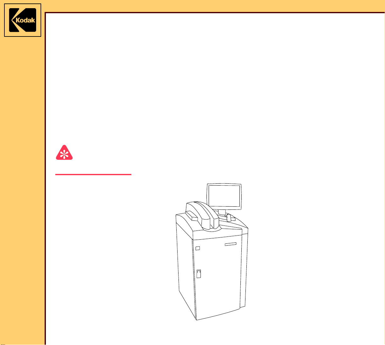
INSTALLATION INSTRUCTIONS
for the
Kodak DirectView CR 825/850 SYSTEMS
Service Codes: 5634, 4825
Important
Qualified service personnel must install this equipment.
Publication No. II4825-1
10MAR06
Supersedes II4825-1
10DEC05
H177_0500AC
Page 2

INSTALLATION INSTRUCTIONS
10MAR06
II4825-1
Page
2 of 72
PLEASE NOTE The information contained herein is based on the experience and knowledge relating to the
subject matter gained by Eastman Kodak Company prior to publication.
No patent license is granted by this information.
Eastman Kodak Company reserves the right to change this information without notice, and
makes no warranty, express or implied, with respect to this information. Kodak shall not be
liable for any loss or damage, including consequential or special damages, resulting from any
use of this information, even if loss or damage is caused by Kodak’s negligence or other fault.
This equipment includes parts and assemblies sensitive to damage from electrostatic
discharge. Use caution to prevent damage during all service procedures.
Table of Contents
Description Page
Safety . . . . . . . . . . . . . . . . . . . . . . . . . . . . . . . . . . . . . . . . . . . . . . . . . . . . . . . . . . . . . . . . 4
Necessary Materials . . . . . . . . . . . . . . . . . . . . . . . . . . . . . . . . . . . . . . . . . . . . . . . . . . . . 6
Tools. . . . . . . . . . . . . . . . . . . . . . . . . . . . . . . . . . . . . . . . . . . . . . . . . . . . . . . . . . . . . 6
Installation . . . . . . . . . . . . . . . . . . . . . . . . . . . . . . . . . . . . . . . . . . . . . . . . . . . . . . . . . . . . 7
Unpacking the Equipment . . . . . . . . . . . . . . . . . . . . . . . . . . . . . . . . . . . . . . . 7
Installing the Equipment . . . . . . . . . . . . . . . . . . . . . . . . . . . . . . . . . . . . . . . . 21
Energizing the System . . . . . . . . . . . . . . . . . . . . . . . . . . . . . . . . . . . . . . . . . . 28
Obtaining a “Session ID” . . . . . . . . . . . . . . . . . . . . . . . . . . . . . . . . . . . . . . . . 29
Doing the Calibration for the TOUCH SCREEN . . . . . . . . . . . . . . . . . . . . . 29
Setting the Site Parameters. . . . . . . . . . . . . . . . . . . . . . . . . . . . . . . . . . . . . . 30
Setting the “User Name” and “Password” . . . . . . . . . . . . . . . . . . . . . . . . . 31
Installing and Setting Up Optional Features . . . . . . . . . . . . . . . . . . . . . . . . 33
Setting the “Global” Parameters . . . . . . . . . . . . . . . . . . . . . . . . . . . . . . . . . 34
Setting the HIS/RIS Parameters. . . . . . . . . . . . . . . . . . . . . . . . . . . . . . . . . . . 39
Adding a PRINTING DEVICE . . . . . . . . . . . . . . . . . . . . . . . . . . . . . . . . . . . . . 43
Adding a STORAGE DEVICE . . . . . . . . . . . . . . . . . . . . . . . . . . . . . . . . . . . . . 51
Setting the Profile Destination Configuration . . . . . . . . . . . . . . . . . . . . . . . 54
Enabling the BAR CODE READER . . . . . . . . . . . . . . . . . . . . . . . . . . . . . . . . 55
Setting the Requirements Fields . . . . . . . . . . . . . . . . . . . . . . . . . . . . . . . . . . 59
Configuring the MONITOR . . . . . . . . . . . . . . . . . . . . . . . . . . . . . . . . . . . . . . . 59
Doing the Configuration for the Kodak DirectView CR LONG-LENGTH
IMAGING SYSTEM . . . . . . . . . . . . . . . . . . . . . . . . . . . . . . . . . . . . . . . . . . . 60
Storing the Setup Data . . . . . . . . . . . . . . . . . . . . . . . . . . . . . . . . . . . . . . . . . . 61
Installing the Kodak REMOTE PATIENT DATA ENTRY STATION (RPDES) 62
Setting the Configuration for the RPDES . . . . . . . . . . . . . . . . . . . . . . . . . . 63
Page 3

INSTALLATION INSTRUCTIONS
10MAR06
II4825-1
Page
3 of 72
Operating the RPDES . . . . . . . . . . . . . . . . . . . . . . . . . . . . . . . . . . . . . . . . . . . 64
Making a SHORTCUT for the RPDES . . . . . . . . . . . . . . . . . . . . . . . . . . . . . . 65
Setting the Host File for the Kodak DirectView CAPTURE LINK SYSTEM. 65
Installing the Kodak DirectView REMOTE OPERATIONS PANEL (ROP) . 66
Checking the Operation . . . . . . . . . . . . . . . . . . . . . . . . . . . . . . . . . . . . . . . . . 67
Page 4
10MAR06
II4825-1
Page
4 of 72
INSTALLATION INSTRUCTIONS Safety
Section 1: Safety
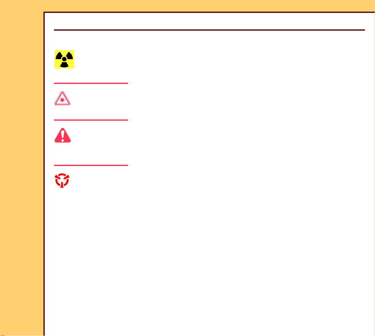
This information defines the safety and information icons used in this publication.
Radiation
This icon is used for conditions that could cause personal injury from radiation.
Laser Warning
This icon is used for conditions when a laser beam could cause injury to a person.
Caution
This icon is used for conditions that could cause injury to a person, or damage to the
equipment or software data.
ESD
Possible damage from electrostatic discharge.
This icon is used for conditions that could cause damage to the equipment.
Electrostatic discharge (ESD) is a primary source of:
• equipment failure
• equipment repairs
A person cannot detect an electrical charge of less than 3,500 V, but 30 V can cause
damage to components in the equipment.
Page 5
INSTALLATION INSTRUCTIONS Safety
10MAR06
II4825-1
Page
5 of 72
Preventive Measures
• Check for an ESD WARNING LABEL before doing any procedure with ESD-sensitive
components. All sensitive components have graphic LABELS that frequently include
instructions. Use all label instructions.
• Wear a GROUNDING STRAP when you touch ESD-sensitive components. Check that the
CLIP remains fastened to a ground that has a clean surface with no paint.
• Repair components in an ESD-protection area or use a PORTABLE GROUNDING MAT.
• When moving ESD-sensitive components from area to area, insert and transport the
components in the special material made for the transport of these components.
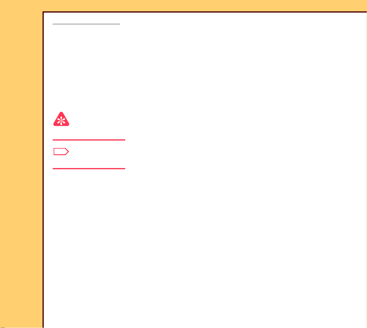
Important
This icon is used for important information.
Note
This icon is used for additional information.
Page 6

10MAR06
II4825-1
Page
6 of 72
INSTALLATION INSTRUCTIONS Necessary Materials
Section 2: Necessary Materials
Tools
Par t No . Description
- - - COMPUTED RADIOGRAPHY CASSETTES
1064930 Kodak INTENSIFYING SCREEN CLEANER AND ANTISTATIC
SOLUTION
TL-5259 COPPER and ALUMINUM FILTERS
- - - tape
3E0899 LINT-FREE CLOTH
TL-4818 DOSIMETER
5E6777 OIL
- - - LEAD APRON or LEAD SHEET
Page 7
10MAR06
II4825-1
Page
7 of 72
INSTALLATION INSTRUCTIONS Installation
Section 3: Installation
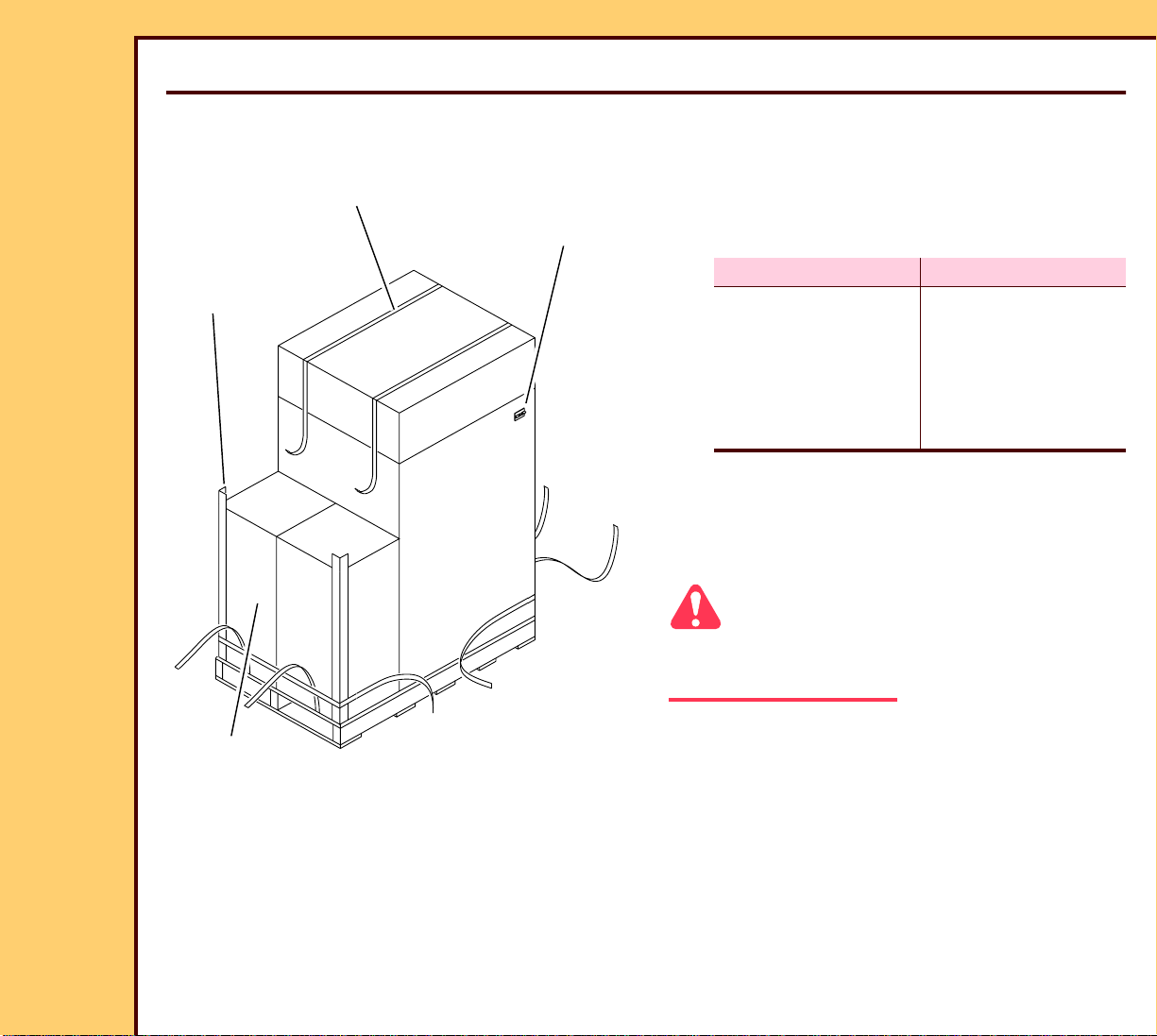
Unpacking the Equipment
1 Check the SHOCK WATCH on the side
3 STRAPS
SHOCK
WATCH
of the carton.
2 Is the SHOCK WATCH red?
2 CORNER
PROTECTORS
2 cartons
H194_0116GCA
H194_0116GC
Yes No
Stop the
installation
Continue with
Step 3.
procedure and call
the Technical
Support Center
(TSC).
3 Record any problems that occur during
this installation. Include this information
in the “OUT OF BOX SURVEY” you
provide to the customer.
Caution
Be careful when you cut the STRAPS. The
STRAPS are tight.
4 Cut the 3 STRAPS.
5 Remove:
• 2 CORNER PROTECTORS
• 2 cartons
– ASSEMBLY KIT 1
– ASSEMBLY KIT 2
6 Unpack the 2 cartons.
Page 8
10MAR06
II4825-1
Page
8 of 72
INSTALLATION INSTRUCTIONS Installation
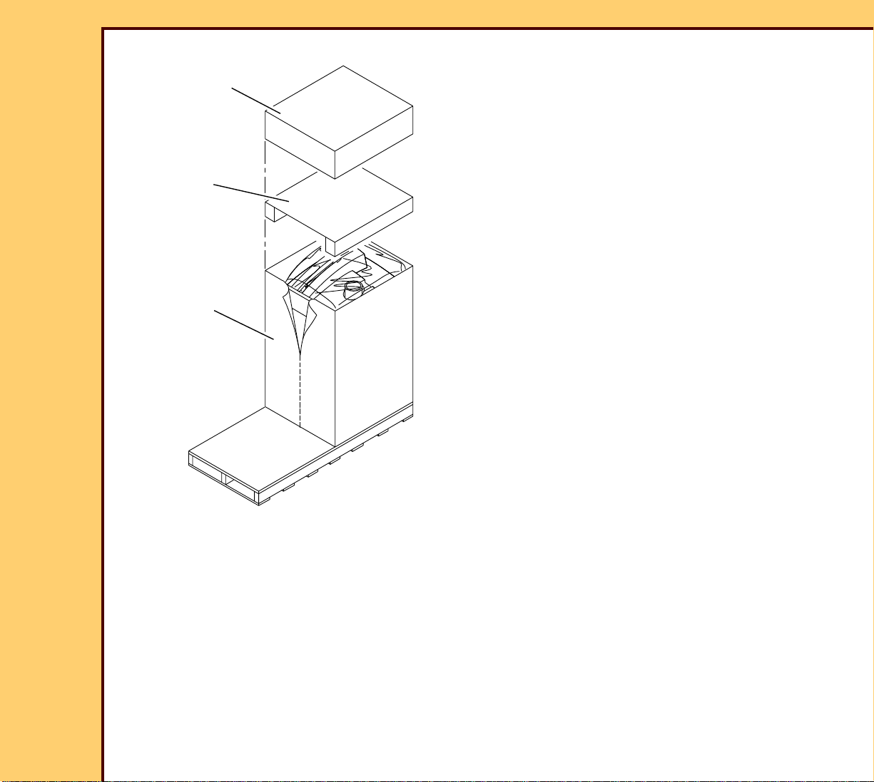
7 Remove:
SHORT CAP
• SHORT CAP
• CORRUGATED SUPPORT
8 Cut the carton.
CORRUGATED
SUPPORT
carton
H194_0117GCA
H194_0117GC
9 Remove the carton.
Page 9
10MAR06
II4825-1
Page
9 of 72
INSTALLATION INSTRUCTIONS Installation
10 Cut the tape.
RAMP
PLASTIC
BAG
11 Remove the RAMP SUPPORT from
behind the RAMP.
12 Align the mark on the RAMP SUPPORT
with the mark on the RAMP.
13 Place the RAMP SUPPORT on the
RAMP.
mark
RAMP
SUPPORT
tape
H194_0118GCA
H194_0118GC
14 Remove:
• RAMP
• PLASTIC BAG
Page 10

10MAR06
II4825-1
Page
10 of 72
INSTALLATION INSTRUCTIONS Installation
Important
Keep the REAR SHIPPING BRACKET.
15 Remove and keep:
• 10 BOLTS
• 4 SIDE SHIPPING BRACKETS
• REAR SHIPPING BRACKET
10 BOLTS
REAR SHIPPING
BRACKET
H194_0119ACA
H194_0119AC
4 SIDE SHIPPING
BRACKETS
16 Fasten the RAMP to the PALLET.
RAMP
PALLET
H194_0120ACA
H194_0120AC
Caution
The weight is 308 kg (680 lb). Use more
than one person to move down the RAMP.
17 Carefully move the system down the
RAMP.
Page 11
10MAR06
II4825-1
Page
11 of 72
INSTALLATION INSTRUCTIONS Installation
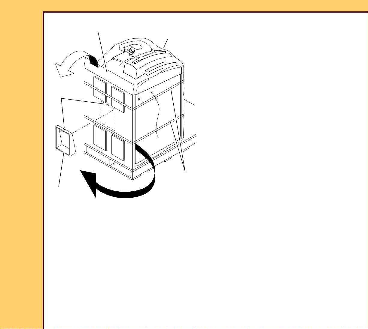
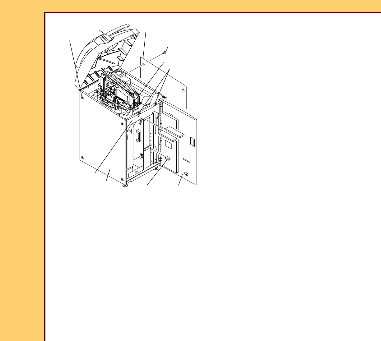
18 Open the FRONT DOOR.
TOP COVER
2 SCREWS
LEFT PANEL
2 SCREWS
19 Loosen the 2 SCREWS.
20 Open the TOP COVER.
21 Remove:
7 SCREWS
2 SCREWS
• FOAM PACKING MATERIAL
• 7 SCREWS
• CROSSBRACE
• 2 SCREWS
• LEFT PANEL
• 2 SCREWS
• RIGHT PANEL
CROSSBRACE
H194_0101GCA
H194_0101GC
RIGHT
PANEL
FOAM PACKING
MATERIAL
FRONT
DOOR
Page 12
10MAR06
II4825-1
Page
12 of 72
INSTALLATION INSTRUCTIONS Installation
22 Check the SHOCK WATCH on the side
of the frame.
23 Is the SHOCK WATCH red?
SHOCK WATCH
H194_1400ACA
H194_1400AC
OPTICS
SHIPPING
BRACKET
Yes No
Stop the installation
procedure and call the
TSC.
24 Remove and discard:
• 2 BOLTS
• OPTICS SHIPPING BRACKET
Continue with
Step 24.
H194_0113ACA
H194_0113AC
2 BOLTS
Page 13
10MAR06
II4825-1
Page
13 of 72
INSTALLATION INSTRUCTIONS Installation
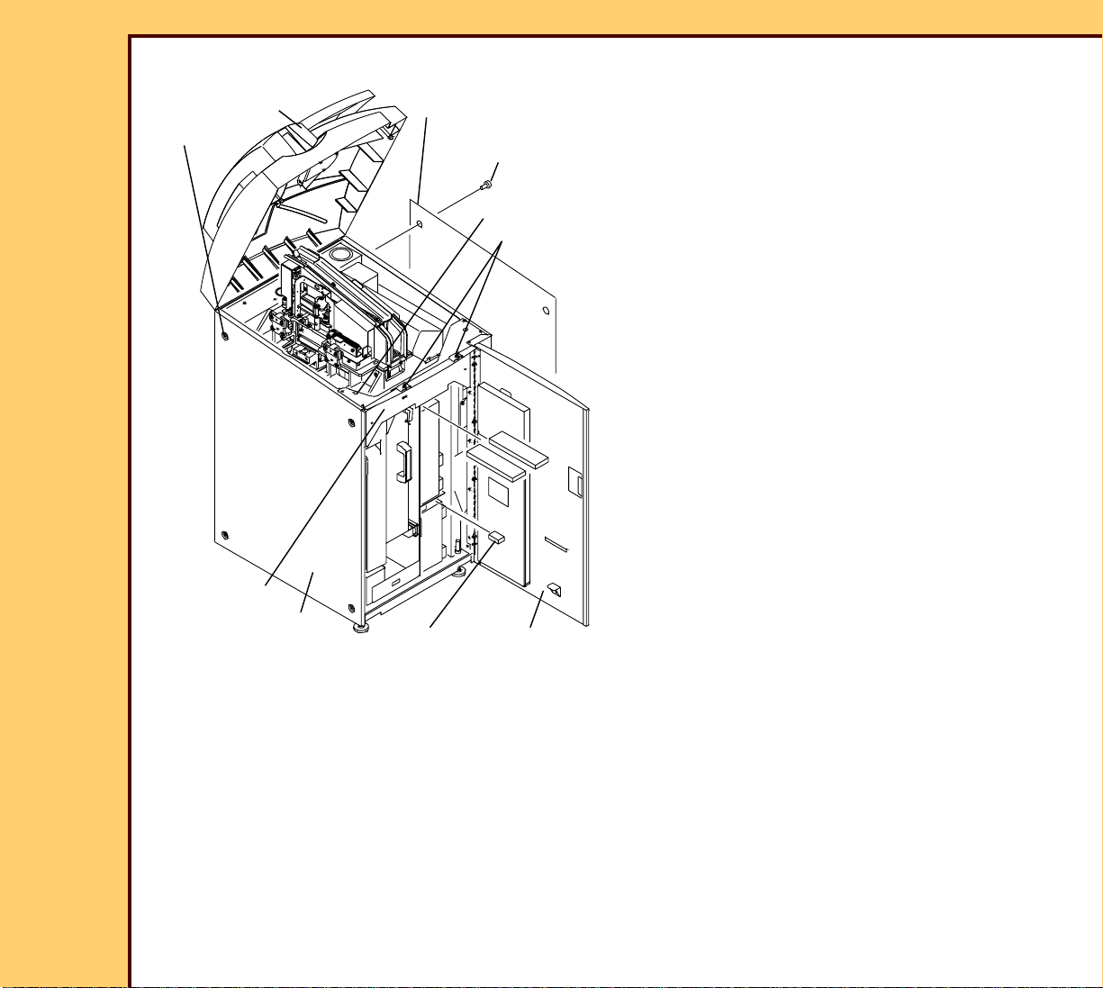
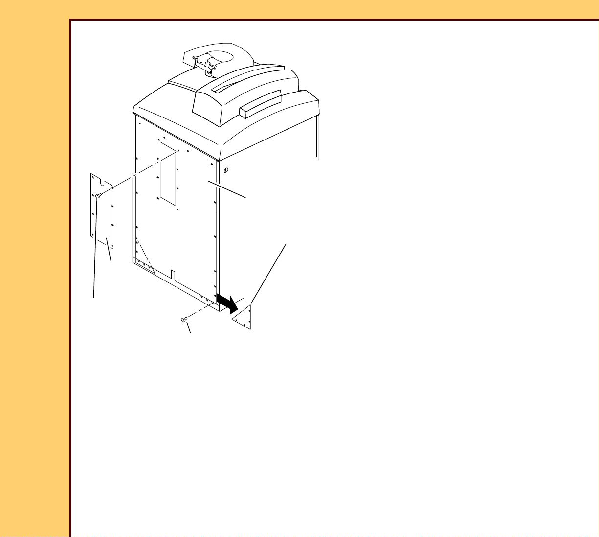
25 Remove the 8 SCREWS from the
REAR PANEL.
26 Remove and discard 2 SHIPPING
PLATES.
27 Install the 8 SCREWS in the REAR
PANEL.
28 Remove:
• 8 SCREWS
• REAR ACCESS PANEL
REAR PANEL
2 SHIPPING PLATES
REAR
ACCESS
PANEL
8 SCREWS
8 SCREWS
H194_0121GCA
H194_0121GC
Page 14
10MAR06
II4825-1
Page
14 of 72
INSTALLATION INSTRUCTIONS Installation
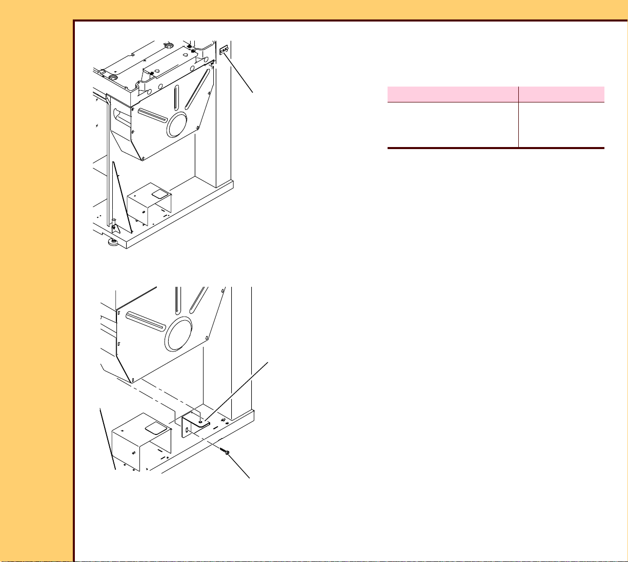
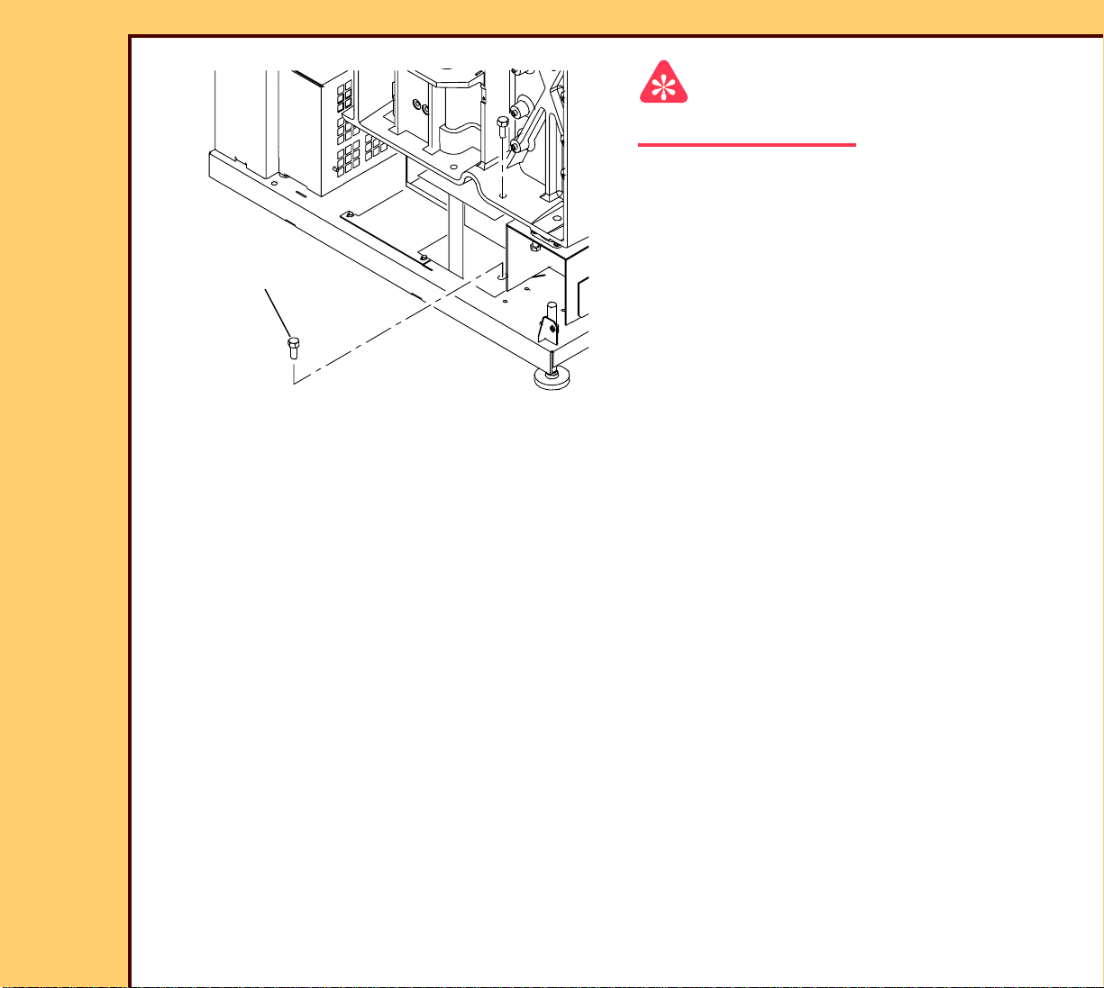
Important
Do not remove the SHIPPING BRACKET.
29 Remove and discard the 4 BOLTS.
30 Remove the SCREW from the ACCESS
PLATE.
4 BOLTS
H194_0123ACA
H194_0123AC
Page 15

10MAR06
II4825-1
Page
15 of 72
INSTALLATION INSTRUCTIONS Installation
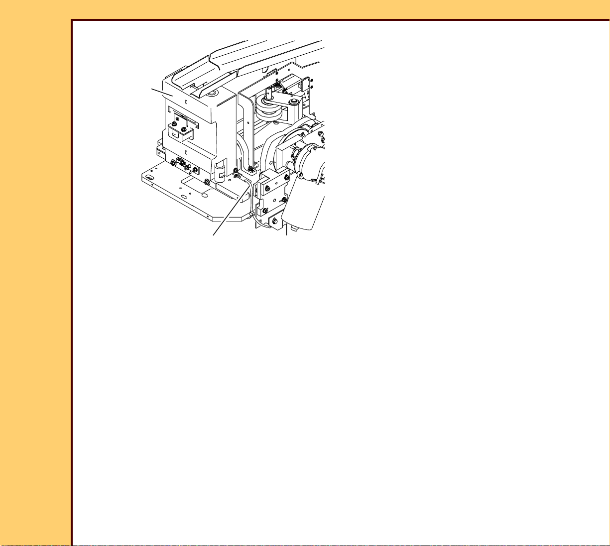
31 Rotate the 2 JACK BOLTS clockwise
FRAME
until the SHIPPING BRACKET is loose.
32 Remove and discard the SHIPPING
BRACKET.
33 Install the SCREW into the ACCESS
PLATE.
34 Rotate the 2 JACK BOLTS
JACK BOLT
SCREW
SHIPPING
BRACKET
ACCESS
PLATE
counterclockwise until the 2 JACK
BOLTS do not touch the FRAME.
H194_0124GCA
H194_0124GC
JACK BOLT
FRAME
Page 16
10MAR06
II4825-1
Page
16 of 72
INSTALLATION INSTRUCTIONS Installation
35 Cut and discard the TIE WRAP from
the CASSETTE HANDLING
CASSETTE
HANDLING
ASSEMBLY
H194_0109ACA
H194_0109AC
TIE WRAP
ASSEMBLY.
Page 17
10MAR06
II4825-1
Page
17 of 72
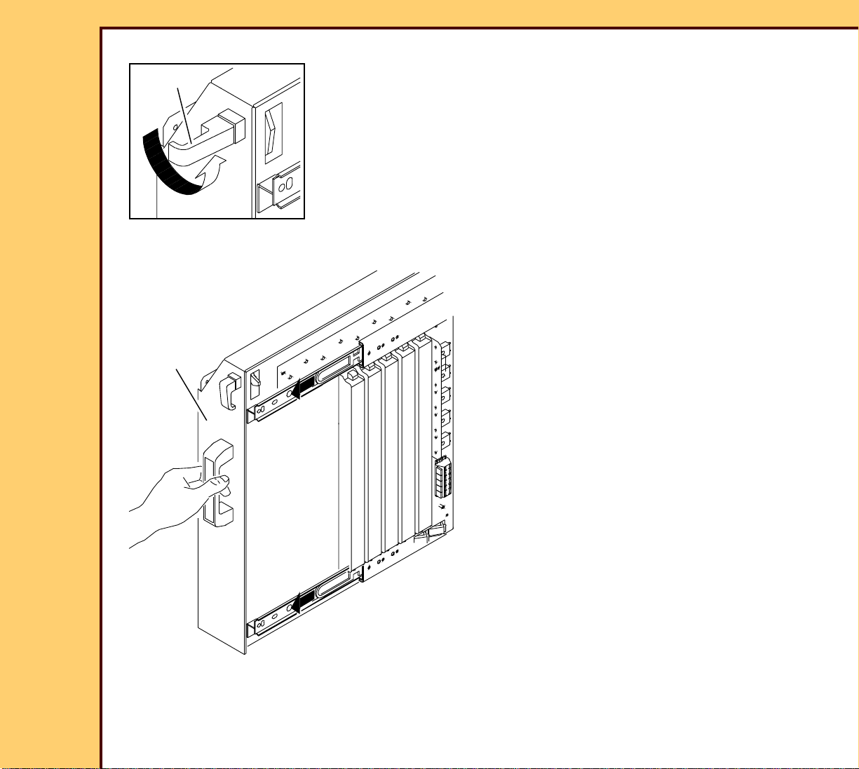
INSTALLATION INSTRUCTIONS Installation
36 Disengage the LATCH on the ERASE
LATCH
LAMP AY.
37 Pull the ERASE LAMP AY from the
system.
ERASE
LAMP AY
H196_0151CCA
H196_0151CC
Page 18

10MAR06
II4825-1
Page
18 of 72
INSTALLATION INSTRUCTIONS Installation
38 Remove and discard the SHIPPING
PLATE.
SHIPPING PLATE
H177_0128GCA
H177_0128GC
Page 19
10MAR06
II4825-1
Page
19 of 72
INSTALLATION INSTRUCTIONS Installation
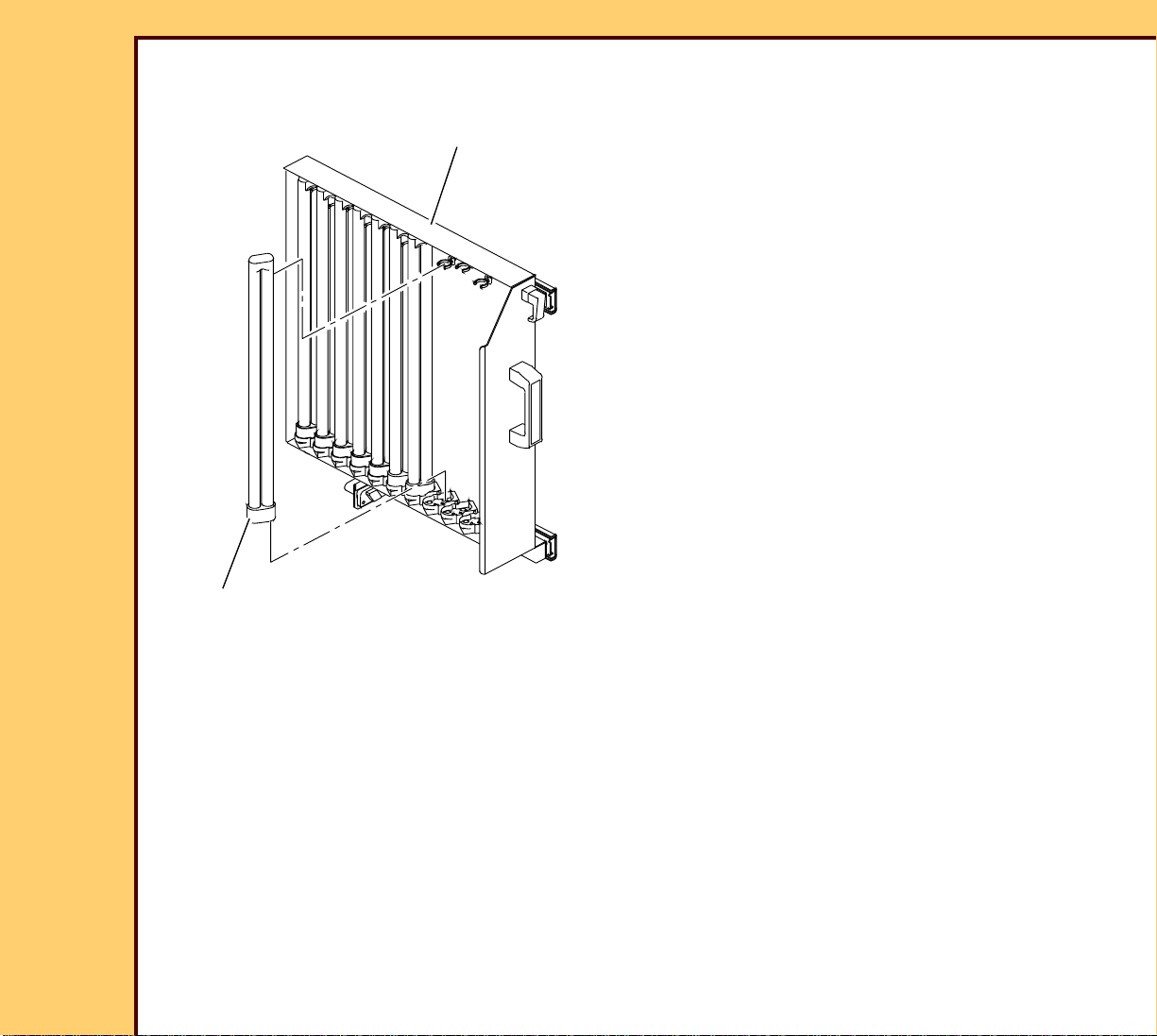
39 Install the 10 ERASE LAMPS into the
ERASE LAMP AY.
ERASE LAMP AY
40 Push the ERASE LAMP AY into the
system.
321
451 2 435
10 ERASE LAMPS
H194_0031GCA
H194_0031GC
Page 20
10MAR06
II4825-1
Page
20 of 72
INSTALLATION INSTRUCTIONS Installation
TOP COVER
2 SCREWS
LEFT PANEL
2 SCREWS
41 Install:
• RIGHT PANEL
• 2 SCREWS
7 SCREWS
2 SCREWS
• LEFT PANEL
• 2 SCREWS
• CROSSBRACE
• 7 SCREWS
42 Close the TOP COVER.
CROSSBRACE
H194_0101GCA
H194_0101GC
RIGHT
PANEL
FOAM PACKING
MATERIAL
FRONT
DOOR
Page 21

INSTALLATION INSTRUCTIONS Installation
10MAR06
II4825-1
Page
21 of 72
Installing the Equipment
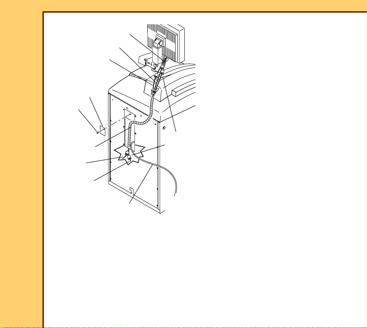
MONITOR
MOUNT
MONITOR
SHOULDER
SCREW
COVER
4 SCREWS
2 SCREWS
SCREW
WIRE
WRAP
BRACKET
MONITOR
POST AY
SPACER
DISK
1 Remove:
• SCREW
• WIRE WRAP
• BRACKET
• COVER
2 Install:
• SPACER DISK
• 2 SCREWS
• MONITOR POST AY
• SHOULDER SCREW
• MONITOR
• MONITOR MOUNT
• 4 SCREWS
H177_0161GCA
H177_0161GC
2 TABS
• MONITOR onto the MONITOR
POST AY
• 2 SCREWS
Important
The COVER must engage the 2 TABS on
the MONITOR MOUNT.
3 Install:
• COVER
• BRACKET
• WIRE WRAP
• SCREW
Page 22
10MAR06
II4825-1
Page
22 of 72
INSTALLATION INSTRUCTIONS Installation
4 Install:
SERIAL CABLE
• 5 FERRITE BEADS to:
POWER CABLE
VIDEO CABLE
PLATE
SCREW
WIRE WRAP
VIDEO
CABLE
POWER
CABLE
H194_0128GCA
H194_0128GC
– NETWORK CABLE to PC
– SERIAL CABLE (COM1)
– both ends of the POWER CABLE
– both ends of the VIDEO CABLE
• PLATE
• SCREW
• WIRE WRAP
5 FERRITE
BEADS
NETWORK
CABLE
Page 23

10MAR06
II4825-1
Page
23 of 72
INSTALLATION INSTRUCTIONS Installation
MONITOR
KEYBOARD
COMPUTER
J
MODEM
3.0 GHz
K
B
C
A
L
I
D
F
optional
BAR CODE
READER
MOUSE
MODEM
2.4 GHz
H
E CABLE
H194_0126HC
G
Page 24

INSTALLATION INSTRUCTIONS Installation
10MAR06
II4825-1
Page
24 of 72
5 Connect:
CABLE Description From: To:
A SERIAL IN MONITOR COMPUTER COM 1 CONNECTOR
B VGA IN MONITOR COMPUTER MONITOR CONNECTOR
C MONITOR POWER MONITOR MONITOR POWER/SOUND CABLE
D Y CABLE BAR CODE
KEYBOARD EXTENSION CABLE
READER
E BAR CODE READER Y CABLE KEYBOARD CABLE
F KEYBOARD
Y CABLE COMPUTER KEYBOARD CONNECTOR
EXTENSION CABLE
G MOUSE MOUSE MOUSE EXTENSION CABLE
H MOUSE EXTENSION MOUSE CABLE COMPUTER MOUSE CONNECTOR
I RS-232 optional MODEM COMPUTER COM 2 CONNECTOR 2.4
GHZ COM 4 on 3.0 GHZ
J NETWORK CUSTOMER
NETWORK
COMPUTER NETWORK CARD
CONNECTOR
K NETWORK MCPU BOARD
(A2)
COMPUTER ONBOARD NETWORK
CONNECTOR
L KEYBOARD KEYBOARD KEYBOARD CONNECTION CABLE
Page 25

10MAR06
II4825-1
Page
25 of 72
INSTALLATION INSTRUCTIONS Installation
6 Remove the optional MODEM from the
POWER ADAPTER
carton.
7 Check that the MODEM DIP
telephone line
SWITCHES on the back of the MODEM
are set correctly. If necessar y, change
RS-232
CABLE
the settings.
8 Connect to the MODEM:
• POWER ADAPTER
optional MODEM
• telephone line
H194_0127ACA
H194_0127AC
8 SCREWS
REAR
ACCESS
PANEL
MODEM DIP SWITCHES
OFF
ON
12345678910
H194_0132ACA
H194_0132AC
• RS-232 CABLE
9 Connect the RS-232 CABLE to the
COM 2 connection on the computer.
Caution
Dangerous Voltage
10 Connect:
• POWER ADAPTER to the power
source
• telephone line
11 Energize the MODEM.
12 Have the TSC make a call to the
telephone number on the MODEM to
check the connection.
13 Install:
• 8 SCREWS
• REAR ACCESS PANEL
Page 26

10MAR06
II4825-1
Page
26 of 72
INSTALLATION INSTRUCTIONS Installation
14 Check the voltage at the site.
15 Select the correct POWER CORD for
the site.
Caution
Dangerous Voltage
16 Connect the POWER CORD to:
• CR 825/850 SYSTEM
• power source
CR 850 SYSTEM
H194_0129GCA
H194_0129GC
POWER CORD
power source
Page 27

10MAR06
II4825-1
Page
27 of 72
INSTALLATION INSTRUCTIONS Installation
17 Place the system in the correct position
at the site.
18 Open the FRONT DOOR.
19 Loosen the 2 LOCKING NUTS.
20 Rotate the 2 HOLD DOWN FEET until
the HOLD DOWN FEET make contact
with the floor.
2 LOCKING
NUTS
H177_0132GCA
H177_0132GC
FRONT DOOR
2 HOLD DOWN FEET
21 Tighten the 2 LOCKING NUTS.
Page 28

INSTALLATION INSTRUCTIONS Installation
10MAR06
II4825-1
Page
28 of 72
Energizing the System
T
ES
/T
PC
UPS
DC
BA
FRONT
DOOR
POWER
LED
Laser Warning
• This equipment uses a visible red
LASER. Prevent direct exposure to the
beam from the LASER when the system
is energized.
• Dangerous Voltage
1 Energize the system.
a Open the FRONT DOOR.
b On the UPS, press and hold the “I/
Test” until a beep sounds.
c Wait 5 seconds.
d Check that the LED on the PC
illuminates and remains illuminated.
e Close the FRONT DOOR.
I/Test
H177_0133GCB
H177_0133GC
/TEST
Line
On Battery
Bypass
On Line
f Wait for the system to initialize.
2 Energize the MONITOR.
Page 29

INSTALLATION INSTRUCTIONS Installation
10MAR06
II4825-1
Page
29 of 72
Obtaining a “Session ID”
Important
You must have a “Session ID” for access to “Service Functions” and “Diagnostics”.
1 Obtain a “Session ID”, see SERVICE BULLETIN 843.
Doing the Calibration for the TOUCH SCREEN
1 From the main menu, click:
• [Key Operator Functions]
• [System Configuration]
• [Next]
• [Next]
• [Next]
• [Calibrate the Touch Screen]
2 Touch the TARGET when it moves to the 3 areas on the screen.
3 Does the cursor position change when you touch the TARGET?
Yes No
a. Touch [YES].
b. Continue with Step 4.
a. Touch [NO].
b. Do Step 1 - Step 3 again.
c. If necessary, install a new
MONITOR.
4 Touch [Main Menu].
Page 30

INSTALLATION INSTRUCTIONS Installation
10MAR06
II4825-1
Page
30 of 72
Setting the Site Parameters
1 From the main menu, touch:
• [Service Functions]
• [Network Configuration]
2 Type:
• “Local IP Address”
• “Computer/Station Name”
• “Subnet Mask”
• “Default Gateway”
• “RAS IP Address Range”
• “Network Speed/Duplex”
3 At the “Microsoft Internet Explorer” message, click [OK].
Note
The system boots.
4 If necessary, at the “AddOnInit-SUCCESS” screen, click [OK].
5 If the “Desktop” screen displays for
more than one minute, click [Restart].
Page 31

INSTALLATION INSTRUCTIONS Installation
10MAR06
II4825-1
Page
31 of 72
Setting the “User Name” and “Password”
Important
You must set up the “User Name” and “Password” for all users on site.
1 At the “Login” screen, for the “User Name” and “Password”, type: SA
2 Click [Enter].
3 Obtain the password from the “System Administrator” (SA).
4 If the SA is not on site, for the SA password, type: SECURITY
5 At the “Change Password” screen, type:
• in the “Current Password” field: SA
• in the “New Password” field the password obtained from Step 3
6 Click:
• [Save Changes]
• [User Configuration]
• [Create New User]
7 At the “Add New User” screen, type:
• in the “User Name” field: AC
• in the “Password” field: 333333
• in the “Full Name” field: Kodak Applications Consultant
• in the “Employee Number” field: 123456
8 Select “Applications Consultant” for “Role”.
9 Click:
• [Save Changes]
• [OK]
10 Do Steps 6 - 9 for all other users on site.
Page 32

INSTALLATION INSTRUCTIONS Installation
10MAR06
II4825-1
Page
32 of 72
11 Click:
• [Back]
• [Back]
• [Logout]
12 At the “Login” screen, type:
• in the “User Name” field: AC
• in the “Password” field: 333333
13 Click [Login].
Important
• The default password length configuration is 6 digits.
• For the Application Consultant (AC) password only, if the password length configuration is:
– more than 6 digits, you must type the number 5 at the end for the additional digits
– less that 6 digits, you must type the corresponding digits up to the password length
Example:
• for a 10-digit password length configuration, type: 3305455555
• for a password length configuration of less than 6 digits, type: 3305
14 At the “Change Password” screen, type:
• in the “Current Password” field: 333333
• in the “New Password” field: 330545
• in the “Confirm New Password” field: 330545
15 Click [Save Changes].
Page 33

INSTALLATION INSTRUCTIONS Installation
10MAR06
II4825-1
Page
33 of 72
Installing and Setting Up Optional Features
Important
It might be necessary to enable upgrade options for each system.
1 From the main menu, touch:
• [Key Operator Functions]
• [System Configuration]
• [Option Registration]
2 Insert the OPTIONS DISKETTE included with the system.
3 Click [ADD UPGRADE OPTIONS].
4 Do Steps 1 - 3 again for all OPTIONS DISKETTE included with the system.
Page 34

INSTALLATION INSTRUCTIONS Installation
10MAR06
II4825-1
Page
34 of 72
Setting the “Global” Parameters
1 From the main menu, touch:
• [Key Operator Functions]
• [System Configuration]
• [Next]
• [Next]
• [Regional Settings]
Important
If you change the “Time Zone”, you must also change the time.
2 Type:
• “Current Date and Time”
• “Time Zone”
• “Language”
Page 35

INSTALLATION INSTRUCTIONS Installation
10MAR06
II4825-1
Page
35 of 72
3 Touch:
• [SAVE CHANGES]
• [BACK]
• [Previous]
• [Delivery Preferences]
• [Default Value]
4 Type:
• “Default Hospital Name”
• “Default Hospital Address”
Page 36

INSTALLATION INSTRUCTIONS Installation
10MAR06
II4825-1
Page
36 of 72
5 Touch:
• [SAVE CHANGES]
• [BACK]
• [Delivery Options]
6 Select “Run in QA Mode”.
Note
“Run in QA Mode” allows the customer or user to review all images before the images are
sent to a “Destination”.
Page 37

INSTALLATION INSTRUCTIONS Installation
10MAR06
II4825-1
Page
37 of 72
7 Touch:
• [SAVE CHANGES]
• [Back]
• [NEXT]
• [Miscellaneous]
8 Check:
• “Default Body Part” is “Chest”
• “Default Projection” is “AP”
• “Default Study Modality” is “CR”
Page 38

INSTALLATION INSTRUCTIONS Installation
10MAR06
II4825-1
Page
38 of 72
9 Touch:
• [NEXT]
• [System Maintenance Defaults]
10 Check that the values are:
• “80%”
• “70%”
• “5”
11 Touch:
• [SAVE CHANGES]
• [Back]
• [Previous]
• [Previous]
Page 39

INSTALLATION INSTRUCTIONS Installation
10MAR06
II4825-1
Page
39 of 72
12 Is the Hospital Information System (HIS) and the Remote Information System (RIS) or
the Kodak DirectView REMOTE OPERATIONS PANEL (ROP) connected?
Yes No
Continue with
Setting the HIS/RIS Parameters.
Adding a PRINTING DEVICE.
Advance to
Setting the HIS/RIS Parameters
“Polling”
1 From the “System Configuration” screen, touch:
• [HIS/RIS - Broker Configuration]
• [PACS Common Configuration]
2 Obtain from the customer:
• “PACS Broker Port” number
• “PACS Broker / AE Title”
• “PACS Broker IP address”
• “Station Name / AE Title”
Page 40

INSTALLATION INSTRUCTIONS Installation
10MAR06
II4825-1
Page
40 of 72
3 Type the correct information in the following fields:
• “PACS Broker Port”
• “PACS Broker / AE Title”
• “PACS Broker IP address”
4 Touch:
• [Back]
• [Polling Configuration]
Important
“Polling” is an option purchased by the customer. The values selected in this screen
determines the “Polling” of all patient information for this “Station” from the “Broker”.
5 If necessary, type the “Station Name / AE Title”.
Page 41

INSTALLATION INSTRUCTIONS Installation
10MAR06
II4825-1
Page
41 of 72
6 If necessary, select:
• “Filter By Station Name”
• “Filter By AE Title”
7 Select or clear the check box:
“Polling” Only “Polling” and “Remote Query” “Remote Query” Only
a. Select the “Remote
Query Active” check box.
b. Clear the “Poll Model
Active” check box.
a. Select:
• “Poll Model Active”
check box
• “Remote Query
a. Select the “Remote
Query Active” check box.
b. Clear the “Poll Model
Active” check box.
Active” check box
Important
• If “Push” is selected, the “Minutes Between Search Updates” could be changed to 720
minutes because the “Broker” will automatically send any new patient information.
• The default times for:
– “Hours Before Current Time” = “3”
– “Hours After Current Time” = “3”
– “Minutes Between Search Updates” = “10”
8 Change the times to:
• “Hours Before Current Time” = “24”
• “Hours After Current Time” = “24”
• “Minutes Between Search Updates” = “3”
9 Touch:
• [SAVE CHANGES]
• [BACK]
• [Push Configuration]
Page 42

INSTALLATION INSTRUCTIONS Installation
10MAR06
II4825-1
Page
42 of 72
Setting the “Push” Option
Important
The “Push” function is determined by the features of the “Broker”.
10 Check the “Verify and Validate” database at the TSC to identify if the “Broker” has the
“Push” function.
11 If the customer wants the “Push” option, select the “Push Connection Active” check box
at each system.
12 Type a value between 10225 - 65535 into the “PACS Push Port Number” field.
Note
• The default number is 5401.
• The same port number can be used for all systems.
13 Type any name into the “PACS Push AE Title” field except the computer name.
14 Record all the data from the “Push” screen.
Page 43

INSTALLATION INSTRUCTIONS Installation
10MAR06
II4825-1
Page
43 of 72
15 The following “Events” from the “DICOM Event Notification” must be “Filtered” for the
PACS port modality of the system:
• Study Started
• Study Updated
• Study Completed
Note
If the information is not “Filtered”, the identified system will receive data for all patients.
16 Provide the information from the “Push” screen to the customer for the “Broker”
equipment.
Adding a PRINTING DEVICE
1 From the Key Operator Menu, touch:
• [Service Functions]
• [Service Utilities]
• [Stop User Interface]
Important
You must have the KEYBOARD and MOUSE connected. See “Installing the Equipment.”
2 Double-click the “MIMDUI” icon.
3 Select Connect>Connect to MiM.
Page 44

10MAR06
II4825-1
Page
44 of 72
INSTALLATION INSTRUCTIONS Installation
Important
• “HARD DISK” is the displayed “Destination”. The parameters must not be changed.
“HARD DISK” must not be deleted.
• For existing parameter settings, see the CR SETUP CD 7F3016.
4 At the “MIM Service Application” screen, touch:
• [Configure]
• [Destination]
5 At the “Installed Destinations” screen, touch:
• [Add]
• [Print]
• [Network]
• [Qualified]
Page 45

10MAR06
II4825-1
Page
45 of 72
INSTALLATION INSTRUCTIONS Installation
Important
For PRINTERS that are not in the “Qualified
Printer List” you must see the “V and V
Database” for a “Qualified” configuration
6 At the “Choose a New Network Print
Destination” screen, select the correct
PRINTER from the list.
7 Click [OK].
8 At the “General” screen, type the
information provided by the Project
Manager.
9 Click [Next].
10 At the “General” screen, type the
correct parameters.
11 Click [Next].
12 In the “Media” screen, select the
correct:
• “Media Size”
• “Media Type”
13 Touch [Next].
Page 46

10MAR06
II4825-1
Page
46 of 72
INSTALLATION INSTRUCTIONS Installation
Important
• For the configuration of a PRINTER that
has 2 or more film sizes, each film size
must be configured with a separate
“Destination”.
• The numbers that the “Media” screen
display might not match the numbers
displayed in the screen.
14 In the “Media” screen, select all the
types that the customer uses.
15 Touch [Finish].
Note
• Only change the default numbers for
qualified “Destinations” when instructed
by the TSC.
• If an item is not checked in the “Media”
or “Supported Items” screens, the
customer will not have access to that
item.
Page 47

10MAR06
II4825-1
Page
47 of 72
INSTALLATION INSTRUCTIONS Installation
16 In the “DICOM” screen, type the correct
parameters.
17 Touch [Next].
18 At the “Supported Items” screen, check
that the correct items are selected.
19 Touch [Next].
Page 48

10MAR06
II4825-1
Page
48 of 72
INSTALLATION INSTRUCTIONS Installation
20 At the “Interpolation” screen, check that
the correct items are selected. See the
“V and V Database” or the CR SETUP
CD 7F3016
21 Touch [Next].
22 At the “Format Types” screen, check
that the correct items are selected.
23 Touch [Next].
Page 49

10MAR06
II4825-1
Page
49 of 72
INSTALLATION INSTRUCTIONS Installation
24 At the “Formatting” screen, check that
the correct items are selected.
25 Touch [Next].
26 At the “Image Processing” screen,
check that the correct items are
selected.
27 Touch [Next].
Page 50

10MAR06
II4825-1
Page
50 of 72
INSTALLATION INSTRUCTIONS Installation
28 At the “AUTORAD” screen, click the
“SCU” tab
29 At the “SCU” screen, check that the
correct items are selected.
30 Touch [Next].
31 At the “M952 Usage” screen, check that
the correct items are selected.
32 Touch [Finish].
33 To add more “Print Destinations”, do
Steps 6 - 32 again.
Page 51

10MAR06
II4825-1
Page
51 of 72
INSTALLATION INSTRUCTIONS Installation
Adding a STORAGE DEVICE
Important
Some systems do not support “DICOM ECHO” if the “Ping” function is disabled.
1 Check that the configuration of the “Destination” is correct.
a At the “Service Application” screen, click “Diagnostics/Network”.
b Select:
• “Ping”
• “DICOM ECHO”
• “Run”
c Type the information for the new “Destination”:
• “IP address”
• “Port Number”
• “AE Title”
d Click [OK].
e If “Passed” displays, click [Cancel] from the “Network Diagnostics” screen and
continue with Step 2.
f If “Passed” does not display, check:
• “Destinations” are correct
• customer network is operating correctly
• PRINTER is energized and set to receive information from the system
g Click [Cancel] from the “Network Diagnostics” screen.
Page 52

INSTALLATION INSTRUCTIONS Installation
10MAR06
II4825-1
Page
52 of 72
2 At the “Installed Destinations” window, touch:
• [Add]
• [Store]
• [Network]
• [Qualified]
3 Touch [OK].
4 At the “General” window, type:
• “Logical Name”
• “IP Address”
5 Touch [Finish].
6 In the “DICOM Information” window,
type the correct information:
• “Port Number”
• “AE Title”
• “Response Message”
7 Touch:
• [OK]
• [Set]
8 At the “Installed Destinations” window,
click [Close].
Page 53

INSTALLATION INSTRUCTIONS Installation
10MAR06
II4825-1
Page
53 of 72
9 Check that the configuration of the “Destination” is correct.
a At the “Service Application” window, select “Diagnostics/Network”.
b Select:
• “Ping”
• “Dicom Echo”
• “Run”
c Type the information for the new “Destination”:
• “IP address”
• “AE Title”
• “Port Number”
d Touch [OK].
e If “Passed” displays, advance to Step g.
f If “Passed does not display, check:
• “Destinations” are correct
• customer network is operating
• STORAGE DEVICE is energized and is set to receive information
g Select “Cancel” from the “Network Diagnostics” window.
10 If all “Destinations” were set, from the “Service Applications” window touch:
• [Connect]
• [Save Configuration]
11 At the prompt, store the data to the MIM DISK.
12 Close the “Service Applications” window.
13 Double-click the “CR Shutdown” icon.
14 Energize the CR 975 SYSTEM.
15 From the main menu touch [Key Operator Functions].
Page 54

INSTALLATION INSTRUCTIONS Installation
10MAR06
II4825-1
Page
54 of 72
16 Check that the new “Destinations” are correct.
17 Do you want to modify the “Existing Profile”?
Yes No
Touch:
• [Make Appropriate]
• [Save Changes]
• [Configuration]
• [Save Configuration]
• [Connect]
• [Exit]
• “CR Shutdown” icon
Touch:
• [Default]
• [Save Changes]
• [Configuration]
• [Save Configuration]
• [Connect]
• [Exit]
• “CR Shutdown” icon
Setting the Profile Destination Configuration
1 From the main menu, touch:
• [Key Operator Functions]
• [System Configuration]
• [Profile Destination]
• [Modify Existing]
2 Obtain the default “Destinations” from your customer.
3 Touch:
• [Save Profile]
• [Back]
Page 55

INSTALLATION INSTRUCTIONS Installation
10MAR06
II4825-1
Page
55 of 72
Enabling the BAR CODE READER
“Country Code”
1 From the main menu, touch:
• [Key Operator Functions]
• [System Configuration]
2 Touch:
• [Next]
• [Bar Code Configuration]
• [Set Country Code]
3 Select the correct option from the list.
4 Touch:
• [BACK]
• [Program Bar Code Scanner]
• [CONFIGURE COUNTRY CODE]
5 Use the BAR CODE READER to read
the bar codes in sequence from the top
of the screen to the bottom of the
screen.
6 Touch [BACK].
Page 56

INSTALLATION INSTRUCTIONS Installation
10MAR06
II4825-1
Page
56 of 72
“Code 39 Full ASCII”
7 Obtain the mode information from the customer.
8 Touch [Code 39 Full ASCII Mode].
9 Use the BAR CODE READER to read
the correct bar code:
• “Code 39 Full ASCII ON”
• “Code 39 Full ASCII OFF”
10 Touch [BACK].
“Automatic Trigger” and “Manual Trigger”
Important
• “Automatic Trigger” indicates that the BAR CODE READER is continually “On”.
• “Manual Trigger” indicates that the BAR CODE READER operates when the TRIGGER is
actuated.
11 Touch [CONFIGURE AUTOMATIC TRIGGER].
Page 57

10MAR06
II4825-1
Page
57 of 72
INSTALLATION INSTRUCTIONS Installation
12 Use the BAR CODE READER to read
“Automatic Trigger” or “Manual Trigger”.
13 Touch [BACK].
“Prefix and Suffix”
14 Touch [CONFIGURE PREFIX SUFFIX].
15 Use the BAR CODE READER to read
the bar codes in the sequence, 1 - 7.
16 Touch [Next].
Page 58

10MAR06
II4825-1
Page
58 of 72
INSTALLATION INSTRUCTIONS Installation
17 Use the BAR CODE READER to read
the bar codes in the sequence, 1 - 7.
18 Touch [Next].
19 Use the BAR CODE READER to read
the test bar code.
20 Does the screen display:
“Valid Scan” “Invalid Scan”
Continue with
Step 21.
Do Step 14 -
Step 20 again.
21 Touch [BACK].
Page 59

INSTALLATION INSTRUCTIONS Installation
10MAR06
II4825-1
Page
59 of 72
Setting the Requirements Fields
1 Obtain from your customer, the required fields to be complete for a patients study.
2 From the main menu, touch:
• [Key Operator Functions]
• [Required Fields]
3 Select the fields obtained in Step 1.
4 Touch:
• [Save]
• [Back]
• [Next]
Configuring the MONITOR
1 Obtain the model information from the back of the MONITOR.
2 From the main menu, touch:
• [Key Operator Functions]
• [System Configuration]
• [Next]
• [Next]
• [Configure Monitor]
Page 60

10MAR06
II4825-1
Page
60 of 72
INSTALLATION INSTRUCTIONS Installation
3 At the “Configure Monitor” screen, select the correct MONITOR from the list.
4 Touch:
• [SUBMIT]
• [MAIN MENU]
Doing the Configuration for the Kodak DirectView CR LONG-LENGTH IMAGING SYSTEM
1 Is the CR LONG-LENGTH IMAGING SYSTEM installed with your system?
Yes No
a. Configure your system for the CR LONG-
LENGTH IMAGING SYSTEM. See the
SERVICE MANUAL for the Kodak DirectView
CR LONG-LENGTH IMAGING SYSTEM
SM1971-1.
b. Continue with Storing the Setup Data.
Continue with Storing the Setup
Data.
Page 61

INSTALLATION INSTRUCTIONS Installation
10MAR06
II4825-1
Page
61 of 72
Storing the Setup Data
1 From the main menu, touch:
• [Key Operator Functions]
• [System Configuration]
• [Save All Configurations]
2 Obtain an empty user reference DISKETTE from the customer.
3 Insert the DISKETTE into the computer.
4 Touch:
• [Floppy]
• [OK]
5 Remove and store the user reference DISKETTE at the installation site.
Page 62

INSTALLATION INSTRUCTIONS Installation
10MAR06
II4825-1
Page
62 of 72
Installing the Kodak REMOTE PATIENT DATA ENTRY STATION (RPDES)
Important
• The site must not use the Dynamic Host Control Protocol (DHCP). DHCP changes the IP
address of the RPDES or the Kodak DirectView REMOTE OPERATIONS PANEL (ROP)
for the following conditions:
– “Site System Shutdown”
– “Site Boot”
– “Site License Expiration”
• The site must provide an IP address that does not change the application computer for
the RPDES.
• The RPDES is an option purchased by the customer.
1 Check:
• system is connected to the site network
• computer must have:
– Microsoft INTERNET EXPLORER 5.0 or higher installed
– Windows 98 or Windows NT 4.0 OPERATING SYSTEM
• options for the RPDES must be actuated from the OPTIONS DISKETTE
• KEYBOARD and MOUSE
2 Insert the OPTIONS DISKETT E.
3 Install the option for the RPDES through the “Upgradeable Options” screen.
Page 63

INSTALLATION INSTRUCTIONS Installation
10MAR06
II4825-1
Page
63 of 72
Setting the Configuration for the RPDES
1 Log on with the key operator information.
2 From the main menu, touch:
• [Key Operator Functions]
• [System Configuration]
• [NEXT]
• [External Devices]
• [Kodak Remote Operation Panel Setup]
Note
The IP address for each connected ROP and RPDES displays.
3 Type the IP address for the computer.
4 Touch [SAVE CHANGES].
Page 64

INSTALLATION INSTRUCTIONS Installation
10MAR06
II4825-1
Page
64 of 72
Operating the RPDES
1 Double-click the “Internet Explorer” icon.
2 At “http://”, type the IP address for the system.
3 Click [Enter].
4 Add the address to the “Favorites” menu.
Caution
If you press [Submit] without typing information, blank records are sent to the system.
5 Type the patient information.
6 Click [Submit].
Page 65

INSTALLATION INSTRUCTIONS Installation
10MAR06
II4825-1
Page
65 of 72
Making a SHORTCUT for the RPDES
1 Select New>SHORTCUT.
2 Click [Browse].
3 Locate the “IEXPLORE.exe” file.
Important
The “-k” option allows Microsoft INTERNET EXPLORER to operate in full screen mode.
4 Add the IP address for the system to the end of the line.
Note
The IP address for the system in this example is 129.126.6.62.
Example: “C:\Program Files\Plus!\MicrosoftInternet\IEXPLORE.EXE -k http://129.126.6.62/
RPDES”
5 Click [Next].
6 Select a name for the new SHORTCUT.
7 Click [Finish].
8 Double-click the “SHORTCUT” icon to check that it operates correctly.
9 Press [Ctrl] + [W] to exit.
Setting the Host File for the Kodak DirectView CAPTURE LINK SYSTEM.
1 Is your system part of the Kodak DirectView CAPTURE LINK SYSTEM?
Yes No
Continue with Step 2. Advance to Step 7.
2 Select C:>winnt>system32>drivers>etc\hosts.
Page 66

10MAR06
II4825-1
Page
66 of 72
INSTALLATION INSTRUCTIONS Installation
3 Use the “Notepad” to open the “Hosts File”.
4 Type the name and IP address of:
• Kodak DirectView CAPTURE LINK SERVER
• all devices in the CAPTURE LINK SYSTEM
5 Select File>Save.
6 Close the window.
7 Click the “Restart” icon.
Installing the Kodak DirectView REMOTE OPERATIONS PANEL (ROP)
1 Install the ROP. See the INSTALLATIONS INSTRUCTIONS for the Kodak DirectView
REMOTE OPERATIONS PANEL 5E2249.
Page 67

INSTALLATION INSTRUCTIONS Installation
10MAR06
II4825-1
Page
67 of 72
Checking the Operation
1 From the main menu, touch:
• [Key Operator]
• [SMPTE Test Pattern]
Page 68

INSTALLATION INSTRUCTIONS Installation
10MAR06
II4825-1
Page
68 of 72
2 Touch [CREATE 35 x 43 cm SMPTE].
3 Send the SMPTE test pattern to a each PRINTER.
4 Locate a DENSITOMETER at the customer site.
5 From the PRINTER, use the DENSITOMETER to measure the density of the gray
patches of the SMPTE test pattern from 0% - 100%, .
SMPTE
Gray Patch
AIM
Density
0% 3.00 +/-0.10
Tolerance
6 Record each gray patch measurement.
7 Compare the measurement to the AIM
density and the tolerance.
10% 2.75 +/-0.10
20% 2.44 +/-0.10
30% 2.16 +/-0.10
40% 1.88 +/-0.10
50% 1.61 +/-0.10
60% 1.33 +/-0.10
70% 1.05 +/-0.10
80% 0.77 +/-0.10
90% 0.49 +/-0.10
100% 0.21 +/-0.10
8 Do all measured densities match the AIM density +/-0.10?
Yes No
Continue with Step 9. a. Check that the MIM “Destinations” are set correctly.
b. Ask the customer to make a call to the equipment
service representative for the PRINTER.
c. Continue with Step 9.
9 From the system, touch [Back].
Page 69

10MAR06
II4825-1
Page
69 of 72
INSTALLATION INSTRUCTIONS Installation
Important
• You must have approval before sending the SMPTE test pattern.
• Sending a SMPTE test pattern directly to the “Hospital Archive” can cause the
WORKSTATION to lock.
• The tolerance of the “AIM density” can increase or decrease to match the customer
specifications and the WORKSTATION.
• Each gray patch displayed must be the size of the PROBE CUP.
10 Send the SMPTE test pattern to each WORKSTATION “destination”.
11 Use the PHOTOMETER to measure the luminance of the gray patches of the SMPTE
test pattern from 0% - 100% on the WORKSTATION MONITOR.
a. Place the PHOTOMETER PROBE on a flat surface to prevent light from being
detected.
b. Energize the PHOTOMETER.
c. Press “UNITS” until the PHOTOMETER displays “fL”.
d. Press “ZERO” until the PHOTOMETER displays “0.00 fL”.
Page 70

10MAR06
II4825-1
Page
70 of 72
INSTALLATION INSTRUCTIONS Installation
SMPTE
Gray Patch
AIM
Luminance
0% 0.12 +/-0.05
Tolerance
12 Record each gray patch measurement.
13 Compare the measurement to the AIM
luminance and the tolerance.
10% 0.35 +/-0.05
20% 0.76 +/-0.05
30% 1.46 +/-0.05
40% 2.71 +/-0.05
50% 4.86 +/-0.05
60% 8.59 +/-0.05
70% 15.26 +/-0.05
80% 26.36 +/-0.05
90% 46.36 +/-0.05
100% 80.00 +/-0.05
14 Do all measured luminance match the AIM luminance +/-0.05?
Yes No
Continue with Step 15. • Ask the customer to make a call to the equipment
service representive for the WORKSTATION to do a
calibration of the WORKSTATION.
• Continue with Step 15.
15 From the “Diagnostic Menu”, run the [Autolooper Test] 10 times for each size
CASSETTE.
16 Use the Kodak DirectView TOTAL QUALITY TOOL to test and adjust the output image
quality.
17 Check that the software version is 3.0 or higher for the ROP. For more information, see
the INSTALLATION INSTRUCTIONS for the Kodak DirectView REMOTE OPERATIONS
PANEL (ROP) 5E2249.
18 Do the Field Service Installation Checklist for the CR SYSTEM 6F5825.
Page 71

INSTALLATION INSTRUCTIONS Installation
10MAR06
II4825-1
Page
71 of 72
19 Record the following for feedback to the Kodak Scan Plus CUSTOMER SERV ICE
SYSTEM:
• total scan counts
• “XN” for the “Activity Code”
• any problems occurred with the installation
• RAM “Activity Code”
• necessary “MGC” or “VC”
• “ST” or any other code
Page 72

INSTALLATION INSTRUCTIONS Installation
10MAR06
II4825-1
Page
72 of 72
Publication History
Publication
Date
Publication
No.
ECO No.
Changed
Pages
File Name Notes
10APR03 II4825-1 ---- All ii4825_1.fm New Publication
16DEC03 II4825-1 ---- 2, 7, 8, 50,
ii4825_1.fm Revised
51, and 73
20JUL04 II4825-1 ---- 28, 31, 32,
ii4825_1.fm Revised
and 70
10DEC05 II4825-1 ---- 1, 5, 10, 19,
ii4825_1.fm Revised
21, 23, 27,
and 28-72
10Mar06 II4825-1 ---- Page 21 ii4825_1.fm Updated
MONITOR
installation
procedure
Kodak, DirectView and Scan Plus are trademarks of Eastman Kodak Company.
Printed in U.S.A. • ii4825_1.fm
EASTMAN KODAK COMPANY
Rochester, NY 14650
HEALTH GROUP
 Loading...