

Page 1
© EASTMAN KODAK COMPANY, 2005 HEALTH GROUP
Confidential
Restricted
Information
{TheoryGuide}{Production}{Health Group}{ExternalAndInternal}
THEORY GUIDE
for the
Kodak DirectView CR 825/850 SYSTEMS
Service Codes: 5634, 4825
Important
Qualified service personnel must repair this equipment.
Publication No. TG4825-1
10DEC05
Supersedes TG4825-1
09JAN04
H177_0500AC
Page 2

THEORY GUIDE
10DEC05
TG4825-1
Page
2 of 120
PLEASE NOTE The information contained herein is based on the experience and knowledge relating to the
subject matter gained by Eastman Kodak Company prior to publication.
No patent license is granted by this information.
Eastman Kodak Company reserves the right to change this information without notice, and
makes no warranty, express or implied, with respect to this information. Kodak shall not be
liable for any loss or damage, including consequential or special damages, resulting from any
use of this information, even if loss or damage is caused by Kodak’s negligence or other fault.
This equipment includes parts and assemblies sensitive to damage from electrostatic
discharge. Use caution to prevent damage during all service procedures.
Table of Contents
Description Page
Equipment Description. . . . . . . . . . . . . . . . . . . . . . . . . . . . . . . . . . . . . . . . . . . . . . . . . . 5
Features and Functions . . . . . . . . . . . . . . . . . . . . . . . . . . . . . . . . . . . . . . . . . . . . . 5
Main Subsystems . . . . . . . . . . . . . . . . . . . . . . . . . . . . . . . . . . . . . . . . . . . . . . . . . . 10
Radiography Theory . . . . . . . . . . . . . . . . . . . . . . . . . . . . . . . . . . . . . . . . . . . . . . . . . . . . 13
Comparison of Film/Screen and Computed Radiography (CR) . . . . . . . . . . . . 13
Overview of CR Technology . . . . . . . . . . . . . . . . . . . . . . . . . . . . . . . . . . . . . . . . . 17
Operations . . . . . . . . . . . . . . . . . . . . . . . . . . . . . . . . . . . . . . . . . . . . . . . . . . . . 17
Exposing the STORAGE PHOSPHOR SCREEN. . . . . . . . . . . . . . . . . . . . . . 17
Stimulating the PHOSPHOR. . . . . . . . . . . . . . . . . . . . . . . . . . . . . . . . . . . . . . 19
Changing Light Energy to an Analog Signal . . . . . . . . . . . . . . . . . . . . . . . . 20
Changing Analog Signals to Digital Signals . . . . . . . . . . . . . . . . . . . . . . . . 21
Processing the Digital Image. . . . . . . . . . . . . . . . . . . . . . . . . . . . . . . . . . . . . 22
Sequence of Operation. . . . . . . . . . . . . . . . . . . . . . . . . . . . . . . . . . . . . . . . . . . . . . . . . . 23
Overview of Workflow Using the CR 825/850 SYSTEM . . . . . . . . . . . . . . . . . . . 23
Before Loading the CASSETTE. . . . . . . . . . . . . . . . . . . . . . . . . . . . . . . . . . . . . . . 24
Loading the CASSETTE . . . . . . . . . . . . . . . . . . . . . . . . . . . . . . . . . . . . . . . . . . . . . 24
Fastening the PLATE . . . . . . . . . . . . . . . . . . . . . . . . . . . . . . . . . . . . . . . . . . . . . . . 26
Preparing to Scan . . . . . . . . . . . . . . . . . . . . . . . . . . . . . . . . . . . . . . . . . . . . . . . . . . 27
Scanning the SCREEN . . . . . . . . . . . . . . . . . . . . . . . . . . . . . . . . . . . . . . . . . . . . . . 28
Erasing the SCREEN . . . . . . . . . . . . . . . . . . . . . . . . . . . . . . . . . . . . . . . . . . . . . . . 29
Inserting the PLATE back into the CASSETTE SHELL . . . . . . . . . . . . . . . . . . . 30
Removing the CASSETTE . . . . . . . . . . . . . . . . . . . . . . . . . . . . . . . . . . . . . . . . . . . 30
STORAGE PHOSPHOR CASSETTE . . . . . . . . . . . . . . . . . . . . . . . . . . . . . . . . . . . . . . . 32
Overview. . . . . . . . . . . . . . . . . . . . . . . . . . . . . . . . . . . . . . . . . . . . . . . . . . . . . . . . . . 32
Size and Resolution of SCREENS. . . . . . . . . . . . . . . . . . . . . . . . . . . . . . . . . . . . . 34
Page 3

THEORY GUIDE
10DEC05
TG4825-1
Page
3 of 120
Fast Scan / Slow Scan Directions. . . . . . . . . . . . . . . . . . . . . . . . . . . . . . . . . . . . . 36
Image Matrix Size . . . . . . . . . . . . . . . . . . . . . . . . . . . . . . . . . . . . . . . . . . . . . . . . . . 37
Reading the BAR CODE LABEL of the CASSETTE . . . . . . . . . . . . . . . . . . . . . . 39
Cassette Handling. . . . . . . . . . . . . . . . . . . . . . . . . . . . . . . . . . . . . . . . . . . . . . . . . . . . . . 41
Overview. . . . . . . . . . . . . . . . . . . . . . . . . . . . . . . . . . . . . . . . . . . . . . . . . . . . . . . . . . 41
DUPLEX CAM AY . . . . . . . . . . . . . . . . . . . . . . . . . . . . . . . . . . . . . . . . . . . . . . . . . . 42
Cassette Entry. . . . . . . . . . . . . . . . . . . . . . . . . . . . . . . . . . . . . . . . . . . . . . . . . . . . . 46
Cassette Transport . . . . . . . . . . . . . . . . . . . . . . . . . . . . . . . . . . . . . . . . . . . . . . . . . 49
Plate Handling . . . . . . . . . . . . . . . . . . . . . . . . . . . . . . . . . . . . . . . . . . . . . . . . . . . . . 52
Optical . . . . . . . . . . . . . . . . . . . . . . . . . . . . . . . . . . . . . . . . . . . . . . . . . . . . . . . . . . . . . . . 54
Overview. . . . . . . . . . . . . . . . . . . . . . . . . . . . . . . . . . . . . . . . . . . . . . . . . . . . . . . . . . 54
LASER . . . . . . . . . . . . . . . . . . . . . . . . . . . . . . . . . . . . . . . . . . . . . . . . . . . . . . . . . . . 56
GALVO . . . . . . . . . . . . . . . . . . . . . . . . . . . . . . . . . . . . . . . . . . . . . . . . . . . . . . . . . . 58
COLLECTOR and PHOTOMULTIPLIER TUBE (PMT). . . . . . . . . . . . . . . . . . . . . . 62
Scan/Erase. . . . . . . . . . . . . . . . . . . . . . . . . . . . . . . . . . . . . . . . . . . . . . . . . . . . . . . . . . . . 68
Overview. . . . . . . . . . . . . . . . . . . . . . . . . . . . . . . . . . . . . . . . . . . . . . . . . . . . . . . . . . 68
PLATE POSITIONING AY . . . . . . . . . . . . . . . . . . . . . . . . . . . . . . . . . . . . . . . . . . . . 70
LEAD SCREW . . . . . . . . . . . . . . . . . . . . . . . . . . . . . . . . . . . . . . . . . . . . . . . . . . . . . 70
EXTRACTION BAR . . . . . . . . . . . . . . . . . . . . . . . . . . . . . . . . . . . . . . . . . . . . . . . . . 71
REFERENCE SENSOR S9 . . . . . . . . . . . . . . . . . . . . . . . . . . . . . . . . . . . . . . . . . . . 73
PLATE PRESENT SENSOR S5 . . . . . . . . . . . . . . . . . . . . . . . . . . . . . . . . . . . . . . . 73
SLOW SCAN MOTOR . . . . . . . . . . . . . . . . . . . . . . . . . . . . . . . . . . . . . . . . . . . . . . . 73
ENCODER. . . . . . . . . . . . . . . . . . . . . . . . . . . . . . . . . . . . . . . . . . . . . . . . . . . . . . . . . 77
ERASE AY . . . . . . . . . . . . . . . . . . . . . . . . . . . . . . . . . . . . . . . . . . . . . . . . . . . . . . . . 78
LAMP CURRENT SENSORS CS1 - CS5 . . . . . . . . . . . . . . . . . . . . . . . . . . . . . . . . 79
Imaging Sequence . . . . . . . . . . . . . . . . . . . . . . . . . . . . . . . . . . . . . . . . . . . . . . . . . . . . . 80
Overview. . . . . . . . . . . . . . . . . . . . . . . . . . . . . . . . . . . . . . . . . . . . . . . . . . . . . . . . . . 80
Scanning the SCREEN - Slow Scan/Fast Scan. . . . . . . . . . . . . . . . . . . . . . . . . . 81
Obtaining the Image Data . . . . . . . . . . . . . . . . . . . . . . . . . . . . . . . . . . . . . . . . . . . 83
Processing the Data . . . . . . . . . . . . . . . . . . . . . . . . . . . . . . . . . . . . . . . . . . . . . . . . 86
Processing the Image. . . . . . . . . . . . . . . . . . . . . . . . . . . . . . . . . . . . . . . . . . . . . . . 87
Logic and Control. . . . . . . . . . . . . . . . . . . . . . . . . . . . . . . . . . . . . . . . . . . . . . . . . . . . . . 89
Overview. . . . . . . . . . . . . . . . . . . . . . . . . . . . . . . . . . . . . . . . . . . . . . . . . . . . . . . . . . 89
Operator Input Compone nts . . . . . . . . . . . . . . . . . . . . . . . . . . . . . . . . . . . . . . . . . 90
BOARDS. . . . . . . . . . . . . . . . . . . . . . . . . . . . . . . . . . . . . . . . . . . . . . . . . . . . . . . . . . 93
Distribution of Images to the Network. . . . . . . . . . . . . . . . . . . . . . . . . . . . . . . . . 102
Overview. . . . . . . . . . . . . . . . . . . . . . . . . . . . . . . . . . . . . . . . . . . . . . . . . . . . . . 102
Sequence of Operation. . . . . . . . . . . . . . . . . . . . . . . . . . . . . . . . . . . . . . . . . . 103
Power Distribution . . . . . . . . . . . . . . . . . . . . . . . . . . . . . . . . . . . . . . . . . . . . . . . . . . . . . 105
Overview. . . . . . . . . . . . . . . . . . . . . . . . . . . . . . . . . . . . . . . . . . . . . . . . . . . . . . . . . . 105
POWER SUPPLY . . . . . . . . . . . . . . . . . . . . . . . . . . . . . . . . . . . . . . . . . . . . . . . . . . . 106
Page 4

THEORY GUIDE
10DEC05
TG4825-1
Page
4 of 120
Power Distribution . . . . . . . . . . . . . . . . . . . . . . . . . . . . . . . . . . . . . . . . . . . . . . . . . 107
INTERLOCK . . . . . . . . . . . . . . . . . . . . . . . . . . . . . . . . . . . . . . . . . . . . . . . . . . . . . . . 109
UNINTERRUPTIBLE POWER SUPPLY (UPS). . . . . . . . . . . . . . . . . . . . . . . . . . . . 111
Logs . . . . . . . . . . . . . . . . . . . . . . . . . . . . . . . . . . . . . . . . . . . . . . . . . . . . . . . . . . . . . . . . . 112
Overview. . . . . . . . . . . . . . . . . . . . . . . . . . . . . . . . . . . . . . . . . . . . . . . . . . . . . . . . . . 112
Error and Activity Log . . . . . . . . . . . . . . . . . . . . . . . . . . . . . . . . . . . . . . . . . . . . . . 113
Error Frequency Log . . . . . . . . . . . . . . . . . . . . . . . . . . . . . . . . . . . . . . . . . . . . . . . 114
Actuation Log . . . . . . . . . . . . . . . . . . . . . . . . . . . . . . . . . . . . . . . . . . . . . . . . . . . . . 114
Glossary. . . . . . . . . . . . . . . . . . . . . . . . . . . . . . . . . . . . . . . . . . . . . . . . . . . . . . . . . . . . . . 115
Page 5

10DEC05
TG4825-1
Page
5 of 120
THEORY GUIDE Equipment Description
Section 1: Equipment Description
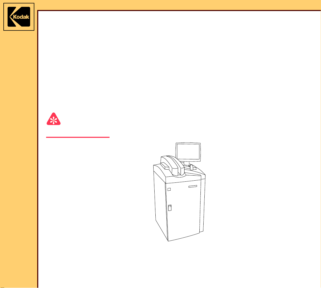
Features and Functions
The Kodak DirectView CR 825/850 SYSTEM is a LASER SCANNER that reads a latent
image made on a STORAGE PHOSPHOR SCREEN during an X-ray exam and provides a
digital image. Physicians and radiologists can then view, improve, store and make a print of
the image, and send the image across a computer network.
Size 63.5 x 73.6 cm (25 x 29 in.)
TOUCH SCREEN
MONITOR
• allows the operator to touch areas displayed on the screen to:
– enter exam and patient information
– view and improve images
• allows the FE to do service diagnostics
BAR CODE
READERS
• EXTERNAL BAR CODE READER:
– hand-held READER
– used to scan the BAR CODE LABEL on CASSETTES and
other BAR CODES used for entering data
• INTERNAL BAR CODE READER:
– automatically scans the BAR CODE LABEL on CASSETTES
when they are loaded
– provides information about the size, speed, and serial number
of the CASSETTE
INTERNAL PC • includes software for image processing and for providing
communication with external devices and the computer network
• access is through the front of the CR 825/850 SYSTEM
Page 6

10DEC05
TG4825-1
Page
6 of 120
THEORY GUIDE Equipment Description
Kodak DirectView
REMOTE
OPERATIONS
PANEL (ROP)
A device that is installed on the wall in an area separate from the CR
825/850 SYSTEM, used for viewing images and entering data. The
ROP includes:
• computer running an INTERNET BROWSER
• TOUCH SCREEN MONITOR - SVGA device with a 600 x 800
pixel resolution
• EXTERNAL BAR CODE READER - can read all formats identified
for the hand-held BAR CODE READER on the CR 825/850
SYSTEM
The ROP allows operators to:
• enter patient, exam, and CASSETTE (PEC) data into a CR 825/
850 SYSTEM
• check patient data
• view scanned X-ray images
• send images to other nodes on the network
PEC data entered through a ROP and sent across the network is
connected with the correct image.
Page 7

10DEC05
TG4825-1
Page
7 of 120
THEORY GUIDE Equipment Description
Configurations • Standalone - the CR 825/850 SYSTEM is not connected to other
CR 825/850 SYSTEMS:
– can include ROPs
– must have access to an output device for viewing the images
or to obtain a printout
• Cluster - 2 or more CR 850 SYSTEMS are in a network:
– can include up to 10 remote devices, for example Kodak
Directview CR 800/850/900/950 SYSTEMS, ROPs, and
Remote Patient Data Entry Stations (RPDES)
– allows all devices in the network to send infor mation to each
other
– must include one SERVER that stores all patient data
Note
• Devices in a cluster configuration can only send information to
other devices in the same cluster. Devices in one cluster cannot
send information to devices in other clusters.
Network
Communications
• The CR 825 SYSTEM will not operate in a cluster.
All CR 825/850 SYSTEMS and ROP devices:
• connect to the 10 Base-T or 100 Base-T Ethernet network of the
facility
• can send information to all connected DICOM digital imaging
equipment that is qualified with the Medical Image Manager (MIM)
and CR 825/850 SYSTEM
• use CATEGORY 5 CABLES to connect to the network
• use a gateway device qualified by Kodak to enable access to the
HIS/RIS system. The customer must provide this device.
Page 8

10DEC05
TG4825-1
Page
8 of 120
THEORY GUIDE Equipment Description
On-site Service • CASTERS allow the CR 825/850 SYSTEM to be moved for
service without leveling
• DATA PLATES and MODIFICATION LABELS are located for easy
access and viewing
• PLUGS and CONNECTORS are identified
• data in the Error and Activity logs can be sorted by field for
troubleshooting, for example by date and error code number
• FEs can view internal diagnostics, including error codes,
component tests, and tests of the SENSORS from the TOUCH
SCREEN MONITOR
Remote Service • remote access options:
– dedicated MODEM connected to the CR 825/850 SYSTEM
– MODEM SERVER provided by the customer
• one point of access to the service functions of all CR 825/850
SYSTEMS on the customer network from the remote service
access connection
• access to all service functions, except running the SCAN/ERASE
and Cassette Handling subsystems
• remote service:
– installing software
– setting up the configuration for the CR 825/850 SYSTEM
– retrieving and clearing Error and Activity Logs
– retrieving Image Processing Library (IPL) diagnostic images
Note
FEs providing remote service cannot view the information about the
patient on images.
Page 9

THEORY GUIDE Equipment Description
10DEC05
TG4825-1
Page
9 of 120
The following tabl e describes the specifications for the number of CASSETTES per hour:
Size CR 825 SYSTEM CR 850 SYSTEM
18 x 24 GP 72 90
24 x 30 GP 62 80
35 x 35 GP 70 90
35 x 43 GP 62 85
18 x 24 HR 70 90
24 x 30 HR 62 80
LONG-LENGTH
60 82
CASSETTE
To ler ance is ± 5
The CR 825 SYSTEM is identical to the CR 850 SYSTEM except the software decreases the
speed.
Page 10
10DEC05
TG4825-1
Page
10 of 120
THEORY GUIDE Equipment Description
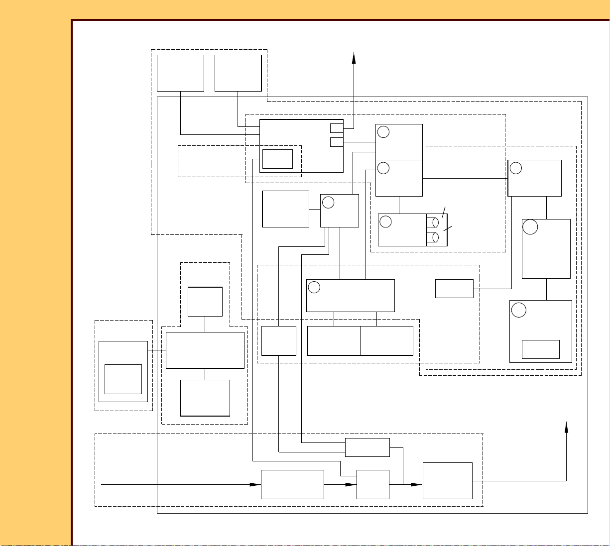
Main Subsystems
CASSETTE
SHELL
CASSETTE
PLATE
TOUCH
SCREEN
MONITOR
Error and Activity
Cassette Entry/
Cassette Transport
Logs
Cassette
Handling
DUPLEX
CAM AY
EXTERNAL
BAR CODE
READER
INTERNAL
PC
LOGS
INTERNAL
BAR CODE
READER
ERASE
LAMPS
to
network
Ethernet
CARDS
A1
MSC
BOARD
A6
SLOW SCAN
CONTROLLER BOARD
SLOW SCAN
ENCODER
SLOW SCAN
A2
MCPU
BOARD
A3
DIGITIZER
BOARD
A5
PMT/DAS
BOARD
Scan/Erase
MOTOR
CR 850 SYSTEM
PMTs
GALVO
Imaging
COLLECTOR
Logic and Control
Optical
A4
GALVO
BOARD
A18
LASER
DRIVER
PRE-
REGULATOR
BOARD
A17
LASER DIODE
DRIVER BOARD
LASER
SCREEN
AC power
90 - 264 V AC
H194_5044DC
Plate
Handling
T1
TRANSFORMER
K1 RELAY
UPS
Power Distribution
PS1
POWER
SUPPLY
DC power to
all BOARDS
and MOTORS
Page 11

10DEC05
TG4825-1
Page
11 of 120
THEORY GUIDE Equipment Description
Subsystem Description See:
CASSETTE • includes:
– STORAGE PHOSPHOR
SCREEN that captures and stores the X-
STORAGE
PHOSPHOR
CASSETTE
ray image for processing
– CASSETTE SHELL that holds the PLATE
• available in 5 sizes and 3 resolutions (GP,
HR, and EHR)
Cassette Handling • loads the CASSETTE into the CR 825/850
SYSTEM
• removes the PLATE from the CASSETTE
SHELL
• after scanning, installs the PLATE in the
CASSETTE SHELL
• allows the CASSETTE to be removed from
the CR 825/850 SYSTEM
Optical • controls and moves the laser beam to the
SCREEN
• captures the blue light emitted from the
SCREEN
Scan/Erase • moves the PLATE at a uniform speed:
– through the scanning area
– to the erase position
• removes the residual image on the SCREEN
by exposing it to intense light
Cassette Handling
Optical
Scan/Erase
• inserts the PLATE into the CASSETTE
SHELL again
Page 12

10DEC05
TG4825-1
Page
12 of 120
THEORY GUIDE Equipment Description
Subsystem Description See:
Imaging • assembles the data from the screen and
Imaging Sequence
changes it to digital format
• processes the image
Logic and Control • processes commands from the operator
• controls the operation of all subsystems
• sends processed images to the network for
distribution
Pow e r D i s t r ib u ti o n • provides power for all subsystems
• includes an UNINTERRUPTIBLE POWER
SUPPLY (UPS)
• has an INTERLOCK SWITCH that actuates
when the FRONT DOOR is opened
Error and Activity
Logs
• records logs of errors in the system
• records user actions
Logic and Control
Power Distribution
Logs
Page 13
10DEC05
TG4825-1
Page
13 of 120
THEORY GUIDE Radiography Theory
Section 2: Radiography Theory
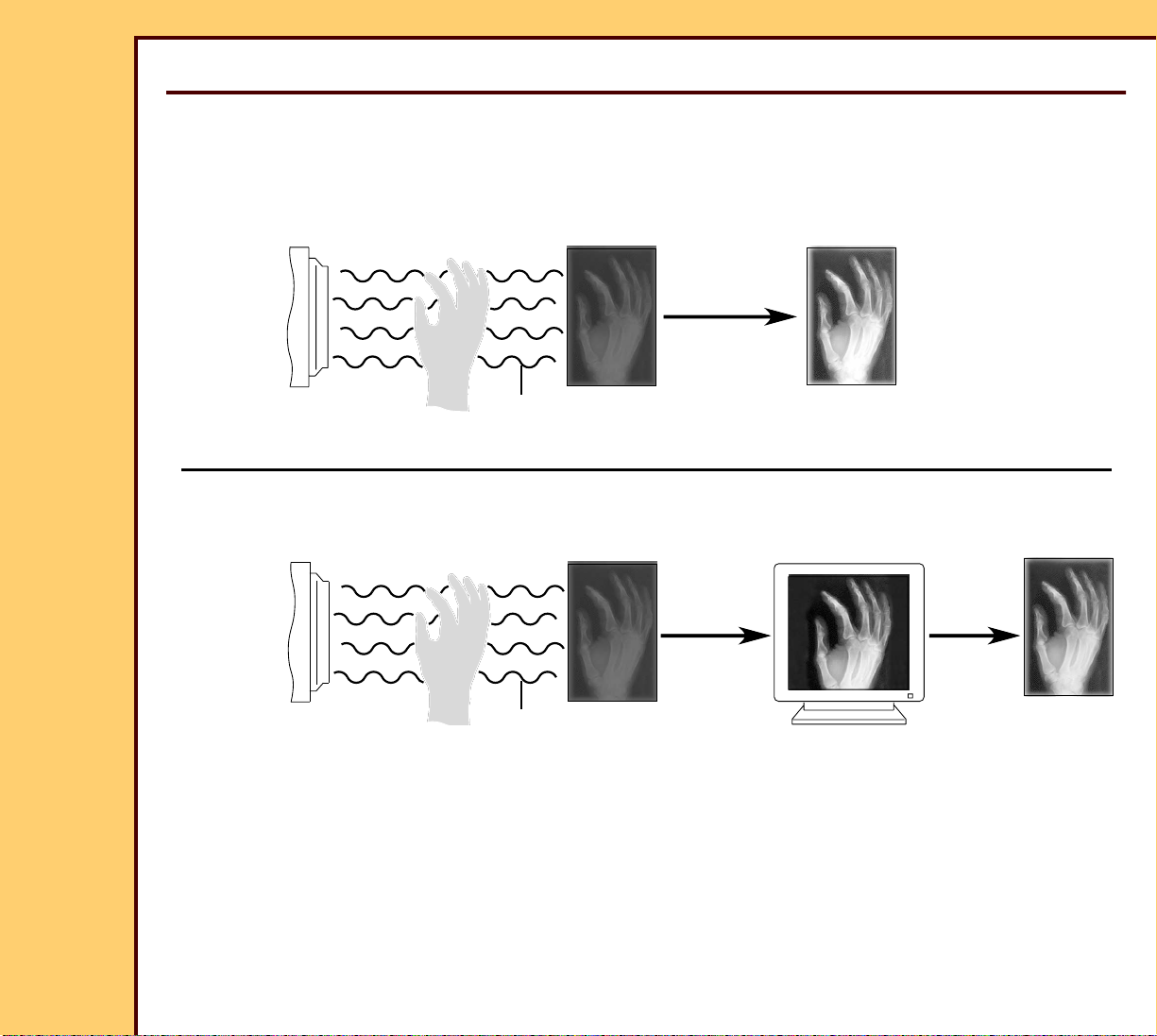
Comparison of Film/Screen and Computed Radiography (CR)
FILM/
X-RAY latent image
TUBE
(On Film)
FILM PROCESSING
visible image
(On Film)
SCREEN
AERIAL
IMAGE
FINAL VISIBLE
IMAGE
(Film or Viewer)
STORAGE
X-RAY
TUBE
(Storage Phosphor)
CONVERSIONS
visible imagelatent image
(CRT)
ENHANCED
PROCESSING
PHOSPHOR
SCREEN
X-rays are used in medical imaging to make an image of given body parts on a surface,
which can be read by a Radiologist or other medical personnel. The available systems for
capturing these images are:
• Screen/film - captures a projection image on an X-ray film
• Computed Radiography (CR) - captures a digital image
Page 14

THEORY GUIDE Radiography Theory
10DEC05
TG4825-1
Page
14 of 120
The following phases are necessary to capture and process projection radiographs for both
screen/film systems and CR systems:
Phase of Image Capture Description
Phase 1 Making the aerial image
In both screen/film and CR systems:
• an X-ray TUBE emits X-rays in the direction of an IMAGE
RECEPTOR
• when the X-rays reach the body of the patient, some are
absorbed by the patient and some are not. The result is an
“aerial” image with varying degrees of X-ray power (varying
numbers of X-ray photons)
Phase 2 Capturing the latent image
When the IMAGE RECEPTOR is exposed to the X-rays in the
aerial image, a latent image is captured on the RECEPTOR:
• screen/film systems - image is captured on sensitized
radiographic film
• CR systems - image is captured on a STORAGE
PHOSPHOR SCREEN. The X-ray photons that reach the
SCREEN charge the PHOSPHOR, making a latent image
on the screen.
Phase 3 Capturing, changing, and
storing the visible image
The latent image must be changed to a visible image, which
can be read by the Radiologist, moved from one place to
another, and stored for use at another time:
• screen/film systems - radiographic film is processed through
chemicals and the latent image is fixed onto the film
• CR systems - the latent image on the STORAGE
PHOSPHOR SCREEN is scanned by a laser beam, which
stimulates the charged PHOSPHOR on the SCREEN. Blue
light is emitted from the stimulated PHOSPHOR, assembled,
and changed into analog electrical signals. The analog
image is then changed into digital signals and processed.
The digital image is stored and displayed by a computer
system and can be routed to other computers and
PRINTERS through a network.
Page 15

THEORY GUIDE Radiography Theory
10DEC05
TG4825-1
Page
15 of 120
The following tabl e compares the analog and digital health image capture systems.
Analog Screen/Film Systems Digital CR Systems
Uses “Rare Earth” SCREENS GADOLINIUM OXYSULFIDE or
Uses a BARIUM FLOUROHALIDE STORAGE
PHOSPHOR SCREEN.
LANTHANUM OXYBROMIDE.
Speed range from 100 - 1000. Screen speed:
• General Purpose (GP), 200 - 250
• High Resolution (HP), 100 - 125
• Enhanced High Resolution (EHR), 100 - 125
Film processing parameters are important
No film processing is necessary.
in determining the quality of the image,
for example chemical temperature and
timing.
It is hard to obtain the same print quality
when copies are necessary because of
The user can print a copy of the digital image
at any time.
variations in GENERATORS,
PROCESSORS, positions, procedures,
and conditions for developing the film.
Overexposing or underexposing an image
normally makes it necessary to expose
the patient to ionizing radiation again.
Image quality is changed by conditions in
the environment, for example temperature
or humidity.
The image cannot be viewed in more
than one place at a time.
Exposure factors do not normally make it
necessary to expose the patient to ionizing
radiation again.
Image quality is not changed by conditions in
the environment.
CR images can be viewed at more than one
place at the same time, in the same building or
in remote nodes on the network.
Page 16

10DEC05
TG4825-1
Page
16 of 120
THEORY GUIDE Radiography Theory
Analog Screen/Film Systems Digital CR Systems
• Recording medium - film
• Output medium - film
• Storing medium - film
• Recording medium - STORAGE
PHOSPHOR SCREEN
• Output medium - film, paper, digital display
• Storing medium - digital
Image density and contrast are controlled
by kilovolts peak (kvP), milliampere
seconds (mA.s), and film type.
Viewing quality can only be improved by
increasing the brightness of the LAMP
that illuminates the film.
The quality of films that are not exposed
correctly cannot be improved.
Density and contrast are controlled by image
processing parameters. kvP, and mA.s continue
to be important image control factors for details
and noise in the digital image.
Digital images can be improved by processing
on a computer to change the density, contrast,
sharpness, and other factors.
Images that were not exposed correctly can be
improved. For example, software parameters
can improve image density and contrast.
Page 17
10DEC05
TG4825-1
Page
17 of 120
THEORY GUIDE Radiography Theory
Overview of CR Technology
Operations
The following operations are necessary to capture the latent image in the STORAGE
PHOSPHOR SCREEN and change it to a digital image that can be viewed on a computer
screen and sent to a PRINTER.
• Exposing the STORAGE PHOSPHOR SCREEN
• Stimulating the PHOSPHOR
• Changing Light Energy to an Analog Signal
• Changing Analog Signals to Digital Signals
• Processing the Digital Image
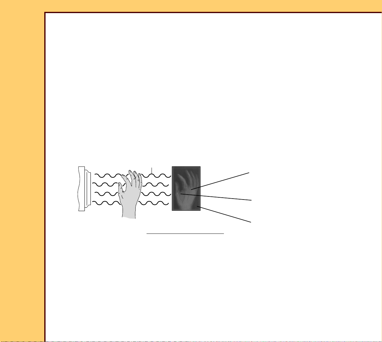
Exposing the STORAGE PHOSPHOR SCREEN
X-RAY
TUBE
H194_5033BC
aerial
image
STORAGE PHOSPHOR SCREEN
Charged storage phosphors
proportional to X-ray energy
absorbed by screen.
latent
image
Lighter values indicate that more
x-rays were absorbed by the
SCREEN - bone tissue
Mid-range values indicate that fewer
x-rays were absorbed by the
SCREEN - soft tissue
Darker values indicate that most
x-rays were absorbed by the
SCREEN - did not pass through the body
Page 18

THEORY GUIDE Radiography Theory
10DEC05
TG4825-1
Page
18 of 120
When a STORAG E PHOSPHOR SCREEN is exposed to X-rays:
• special PHOSPHOR on the SCREEN absorbs the radiation in degrees of intensity
determined the body par t and the type of SCREEN:
– soft body tissues absorb a small quantity of radiation - these areas are indicated in the
X-ray image by mid-range values
– bone tissues absorb most of the radiation - these areas are indicated in the X-ray
image by light values
– X-rays that do not hit any obstructions are indicated in the X-ray image by dark values
– High Resolution SCREENS absorb less energy than General Purpose SCREENS
• SCREEN has a latent image in the areas that were exposed to the radiation. The quantity
of stored energy or charge on the SCREEN is proportional to the quantity of
X-ray energy absorbed by the SCREEN.
Characteristics of the
STORAGE P HOSPHOR
SCREEN
Description
X-ray absorption About 50% of the X-ray energy is released in the form of
fluorescence when the SCREEN is exposed. The X-ray energy
remaining makes the latent image on the SCREEN.
Photostimulable
luminescence
When the charged PHOSPHOR on the SCREEN is stimulated by
light, the PHOSPHOR releases or discharges blue light proportional
to the energy the PHOSPHOR has stored.
Fading The latent image fades with time, but it is possible to read data from
the SCREEN for a number of days after scanning.
Residual image After a SCREEN is erased by exposing it to light, it keeps some
charge from the latent image. This charge does not make the
SCREEN less effective when it is used again.
Page 19

10DEC05
TG4825-1
Page
19 of 120
THEORY GUIDE Radiography Theory
Characteristics of the
STORAGE P HOSPHOR
SCREEN
Description
Signal accumulation Signals can accumulate on SCREENS that are not used for more
than 24 hours. Erasing these SCREENS decreases the residual
image to the optimum range for using the SCREEN again. Failure to
erase these signals can result in artifacts.
Long life The photostimulable luminescent quality of the SCREEN does not
decrease with time. The life of a SCREEN can be decreased by
damage to the material.
Stimulating the PHOSPHOR
It is necessary to stimulate the PHOSPHOR in the SCREEN to read the latent image. The
following components of the CR systems provide this function:
• light source:
– exposes the SCREEN with high-intensity light that stimulates the electrons and causes
the electrons to be luminescent
– laser beam moves from one side of the SCREEN to the other to ex pose the image
• DEFLECTOR:
– moves the laser beam across the SCREEN and then back to the starting position. At
the same time, the SCREEN moves perpendicular to the scanning direction of the
laser beam.
– is continually monitored and adjusted to check that the scanning operation is correct
and has a continual speed
• scanning optics:
– focuses and shapes the laser beam, keeping the speed and angle of the beam the
same when it moves across the SCREEN
– angle of a laser beam determines the size, shape, and speed of the beam. An
example is the beam of a flashlight moving across a flat surface from one edge to the
center and to the other edge.
Page 20

THEORY GUIDE Radiography Theory
10DEC05
TG4825-1
Page
20 of 120
Changing Light Energy to an Analog Signal
The following components of CR systems change the light energy in the exposed SCREEN to
an analog signal:
• LIGHT COLLECTOR:
– provides the collection of the blue light emitted when the SCREEN is stimulated by the
laser beam
– CR 825/850 SYSTEM uses an INTEGRATING CAVITY with MIRRORS to provide the
collection of the blue light
• BLUE FILTER:
– does not allow any red light reflected from the SCREEN to reach the LIGHT
DETECTORS
– allows only the blue light to reach the LIGHT DETECTORS
• LIGHT DETECTORS:
– are normally PHOTOMULTIPLIER TUBES (PMT)
– receive light that enters the COLLECTOR
– change the light photons into electrons when the photons enter through a
PHOTOCATHODE. When the electrons move through the LIGHT DETECTORS, the
electrons increase in number - “gain”.
– when more than one LIGHT DETECTOR is used in a system, the system adds and
changes the signals into one output. The output from the added PMTs can include
frequencies that are outside of the limits of the system - “noise”. An ANALOG FILTER
limits this noise.
Page 21
THEORY GUIDE Radiography Theory
10DEC05
TG4825-1
Page
21 of 120
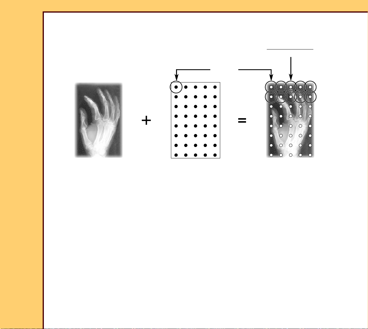
Changing Analog Signals to Digital Signals
SAMPLING
Y
image
sample
grid
X
analog image digital image
(continual values) (discrete values)
pixel code value
(0 - 4095)
image
matrix
H194_5014HC
Analog signals are changed to digital signals by sampling the blue light from the STORAGE
PHOSPHOR SCREEN and moving it through an ANALOG-TO-DIGITAL CONVERTER to
make a digital value for the br ightness of each sample.
Sampling is similar to making a photograph of the signal at a given time. The sample has
both a horizontal and a vertical value. The size of the sample is defined in the system
software for both the horizontal and ver tical directions.
• The horizontal value indicates a point in time in the motion of the laser beam across the
SCREEN.
• The vertical value indicates a line on the screen at a right angle to the scanning direction.
Page 22

THEORY GUIDE Radiography Theory
10DEC05
TG4825-1
Page
22 of 120
If you find both the horizontal and the vertical points of the sample on an imaginary matrix,
similar to the one in the graphic, the result indicates one pixel in the digital image.
Continual analog input values are changed to output values. In this process, the replacement
of small ranges of analog input values with one digital output value occurs. The digital output
value indicates one pixel of infor mation on the TOUCH SCREEN MONITOR.
The output is a linear digital signal. The CR 825/850 SYSTEM emits a 16-bit digital signal
with a total signal range of 65,536 levels. Because it is not possible for the human eye to see
this range of separate values, the CR 825/850 SYSTEM changes the 16-bit linear image data
to 12-bit log data. This 12-bit log provides data from 0 - 4095 values. These values are used
in the CR 825/850 SYSTEM.
Processing the Digital Image
Digital imaging allows users to improve diagnostic images by processing the images. After the
digital image is made, the digital data is processed using parameters set up in the software.
In the CR 825/850 SYSTEM, this processing occurs in the INTERNAL PC.
Examples of image processing used for digital images:
• segmentation
• tone scaling
• edge enhancement
• brightness - level
• contrast - window
Page 23

10DEC05
TG4825-1
Page
23 of 120
THEORY GUIDE Sequence of Operation
Section 3: Sequence of Operation
Overview of Workflow Using the CR 825/850 SYSTEM
1 The Radiology Department receives an exam request.
2 The Radiologist, the operator, assembles the patient information. Examples of patient
information are patient name, ID, and accession number.
Note
If the facility has a Hospital Information System/Radiographic Information System (HIS/RIS)
that is HL-7 compatible, the patient infor mation can be automatically downloaded to the
CR 825/850 SYSTEM through a HIS/RIS gateway. If no automatic connection is available, the
information can be manually entered at a ROP or a CR 825/850 SYSTEM.
3 The operator can select network nodes to send the image data to.
4 The operator uses a CR CASSETTE to do the exam, capturing the latent image on the
STORAGE PHOSPHOR SCREEN.
5 Using the CR 825/850 SYSTEM or the ROP, the operator enters the CASSETTE ID
Information by scanning the CASSETTE BAR CODE or entering it manually.
6 The operator inserts the exposed CASSETTE into the CR 825/850 SYSTEM. The system
scans the SCREEN, capturing the latent image on the SCREEN and changing it to a
digital image. After scanning, the SCREEN is automatically erased and inserted into the
CASSETTE SHELL.
7 The CR 825/850 SYSTEM processes the image. If the system is in:
• Pass-Through Mode - the image is automatically sent to all network nodes
• QA Mode - the operator can process the image and then send it to other network
nodes
8 If necessary, the image can be processed and sent to networ k nodes again.
Page 24

THEORY GUIDE Sequence of Operation
10DEC05
TG4825-1
Page
24 of 120
Before Loading the CASSETTE
1 After initializing, the CR 825/850 SYSTEM is ready to receive a CASSETTE for scanning.
2 The Radiology Technologist uses a Computed Radiology (CR) CASSETTE to capture the
latent image of the body part on the SCREEN.
Status Summary: Ready to Receive a CASSETTE
• DUPLEX CAM is at the home position 1
• DRIVE ROLLERS and IDLER ROLLERS are in contact with the
CASSETTE
• PIVOTING PLUSH is in the open position
• LIGHT SEAL BAR is in the open position
• CASSETTE DRIVE MOTOR is stopped
• EXTRACTION BAR is at the home position
Loading the CASSETTE
1 The operator loads the CASSETTE into the INPUT SLOT until the CASSETTE reaches
the CASSETTE ENTRY SENSOR S1.
2 The CASSETTE ENTRY SENSOR S1 detects the CASSETTE.
Note
The MSC BOARD continually monitors the CASSETTE LOAD SENSOR S2. At the S2
SENSOR, the system must detect a CASSETTE within 5 seconds or an error message
displays.
3 The INTERNAL BAR CODE READER reads the size, speed, and serial number of the
CASSETTE, then:
• emits a sound
• sends information to the MCPU BOARD A2:
– “CASSETTE Detected” message
– size of the CASSETTE
Page 25

THEORY GUIDE Sequence of Operation
10DEC05
TG4825-1
Page
25 of 120
4 The MCPU BOARD A2 sends:
• “CASSETTE Detected” message to the MSC BOARD A1
• “Scan Request” message to the INTERNAL PC
5 The INTERNAL PC:
• checks that it has the quantity of memory necessary to receive an image
• makes a raw image file to receive the image
• sends a “Scan Request Reply” message to the MCPU BOARD A2 with a value of
“OK”
6 The MCPU BOARD A2:
• sends a message to the MSC BOARD A1 to load the CASSETTE
• sends the information about the size and speed of the CASSETTE to the DIGITIZER
BOARD
Note
If the BAR CODE readout is not successful, the operator must enter the data manually. When
BAR CODE data is entered manually, the data is provided by the INTERNAL PC and not the
BAR CODE READER.
7 The CASSETTE DRIVE MOTOR M2 actuates. The MOTOR drives the TIMING BELTS,
which rotate the DRIVE ROLLERS.
8 The DRIVE ROLLERS drive the CASSETTE to the back until the CASSETTE REAR
SENSOR S3 detects the CASSETTE.
9 The CASSETTE REAR SENSOR S3 sends a signal to the MSC BOARD A1 to
deactuate the MOTOR.
10 After a delay of 20 ms, the MSC BOARD A1 deactuates the MOTOR.
Page 26

10DEC05
TG4825-1
Page
26 of 120
THEORY GUIDE Sequence of Operation
Status Summary: CASSETTE Loaded
• DUPLEX CAM is in the home position
• DRIVE/IDLER ROLLERS are engaged on the CASSETTE
• CASSETTE is at the CASSETTE REAR STOP and the CLAMP
BARS are open
• CASSETTE DRIVE MOTOR M2 is stopped
• PLATE remains inside the CASSETTE
• HOOKS on the EXTRACTION BAR are not extended
Fastening the PLATE
1 The DUPLEX CAM moves from position 1 directly to position 3. See “DUPLEX CAM
AY.”
2 When the CAM rotates, the SLED CAM and the HOOK CAM execute the following
actions. The first degrees of the CAM rotation move the HOOKS up. The remaining part
of the rotation releases the LATCHES of the CASSETTE and fastens the PLATE to the
EXTRACTION BAR.
• SLED CAM actions:
– SLED PLATE moves 1.5240 cm (0.600 in.) forward
– PIVOTING PLUSH rotates to make a light-tight environment around the
CASSETTE
• HOOK CAM actions:
– HOOK CAM moves against the HOOK YOKE FOLLOWER, which starts the
mechanical sequence to extend the HOOKS on the EXTRACTION BAR into the
LATCH AY. See “Plate Handling.”
– With the HOOKS in position inside the CASSETTE, the forward motion of the
SLED causes the SPRING-LOADED LATCH inside the PLATE to release and
fastens the PLATE to the EXTRACTION BAR.
3 The MSC BOARD A1 sends a signal to the MCPU BOARD that the CASSETTE is
loaded.
Page 27

10DEC05
TG4825-1
Page
27 of 120
THEORY GUIDE Sequence of Operation
Status Summary: PLATE Fastened
• DUPLEX CAM has reached position 3
• SLED is 1.524 cm (0.600 in.) forward from the home position
• CLAMP BARS are holding the CASSETTE
• PLATE is fastened to the EXTRACTION BAR
• EXTRACTION BAR is at home position with the fastened
PLATE
• PIVOTING PLUSH has made a light-tight environment
around the CASSETTE
• DUPLEX CAM MOTOR M1 is de-energized
Preparing to Scan
1 The SLOW SCAN MOTOR starts rotating the LEAD SCREW, pulling the PLAT E down
from the CASSETTE.
• When the EXTRACTION BAR moves down to the position immediately before
scanning starts, the LOWER ARM of the PLATE POSITIONING AY moves forward to
touch the back of the PLATE, which is partially out of the CASSETTE SHELL. The
LOWER ARM keeps the PLATE from touching the WALLS of the CASSETTE when it
moves out of the CASSETTE.
• After the LOWER ARM moves forward to touch the back of the PLATE, the UPPER
ARM of the PLATE POSITIONING AY also moves forward. It keeps the larger PLAT E
steady during scanning and when they leave and move back into the CASSETTE.
2 When the PLATE is moving into the start of scan position, the MCPU BOARD A2
energizes the PMTs and sets the SIGNAL CHANNEL for the PMTs to 0.
Page 28

THEORY GUIDE Sequence of Operation
10DEC05
TG4825-1
Page
28 of 120
3 The PLATE PRESENT SENSOR S5 detects that a PLATE is fastened and sends a
message of the status to the MSC BOARD A1.
Status Summary: Prepared for Scanning
• PMTs are energized
• SIGNAL CHANNEL is set to 0
Scanning the SCREEN
1 The MCPU BOARD A2:
• actuates the GALVO
• sends a signal to the MSC BOARD A1 to start the scan, which star ts the SLOW
SCAN MOTOR
• sends a signal to the INTERNAL PC that the scan is starting
2 The INTERNAL PC displays a TIMED PROGRESS BAR on the TO UCH SCREEN
MONITOR. This is a graphic display only and not a real-time indication of the status of
the scanning operation.
3 The SLOW SCAN MOTOR rotates, moving the SCREEN at a continual speed through
the field of scan in the slow scan direction.
4 The GALVO BOARD A4 controls the motion of the laser beam across the SCREEN in
the fast scan direction. The SCREEN is scanned one pixel at a time, one line at a time.
See “Scanning the SCREEN - Slow Scan/Fast Scan.”
Note
• The fast scan motion is an almost horizontal trace across the SCREEN, from the back of
the SCREEN toward the front. When it reaches the end of a line, it does a fast retrace to
start another line. During the scanning, the SCREEN is moving down at a controlled
speed to make each fast scan trace one pixel line higher up on the SCREEN than the line
before. The result is that the fast scan is in a slightly diagonal trace across the SCREEN.
• The slow scan runs for a determined number of lines in the vertical direction. A set
number of samplings occur for each line. The number is determined by the size of the
Page 29

THEORY GUIDE Sequence of Operation
10DEC05
TG4825-1
Page
29 of 120
SCREEN. Both the number of lines and the number of samplings are set up in the
calibration for that size of SCREEN.
5 When the end of the scan is reached, the MSC BOARD A1 sends a status message to
the MCPU BOARD A2.
6 The MCPU BOARD A2 de-energizes the PMTs, GALVO, and the LASER.
7 The MCPU BOARD A2 sends a “Scan End” message to the INTERNAL PC. The TIMED
PROGRESS BAR displays until the image is transferred to the INTERNAL PC.
Erasing the SCREEN
1 The MCPU BOARD A2 sends an “Erase Plate” command to the MSC BOARD, which
sends a signal to the SLOW SCAN to start the erasing operation.
2 The SLOW SCAN MOTOR actuates and moves the SCREEN into the erase position,
determined by the counts of the SLOW SCAN ENCODER.
3 The SLOW SCAN MOTOR stops and waits for a response from the MCPU BOARD A2.
4 The MCPU BOARD A2 sends the “Erase” command and time to the MSC BOARD A1,
which actuates the ERASE LAMPS.
5 The ERASE LAMPS illuminate for 2 - 16 seconds to remove the image from the
SCREEN.
Note
The length of time the ERASE LAMPS illuminate is determined by the highest pixel code
value of the image that was scanned. If one pair of LAMPS is not operating, the time
increases by a factor of 2. If more than one pair of LAMPS is not operating, a message
displays on the TOUCH SCREEN MONITOR.
6 When the SCREEN is erased, the MSC BOARD A1 sends the “Erase Done” status to
the MCPU BOARD A2.
Page 30

THEORY GUIDE Sequence of Operation
10DEC05
TG4825-1
Page
30 of 120
Inserting the PLATE back into the CASSETTE SHELL
1 The MCPU BOARD A2 issues a command to the MSC BOARD A1 to:
• return the EXTRACTION BAR to the home position
• insert the SCREEN into the CASSETTE
2 The MSC BOARD A1 reverses the SLOW SCAN MOTOR, which moves the PLATE up
into the open CASSETTE SHELL.
3 The PLATE POSITIONING AY guides the PLATE into the CASSETTE SHELL from the
back side.
4 When the EXTRACTION BAR reaches the home position, the SLOW SCAN MOTOR
stops. At the home position, the ENCODER counts are the saved value.
Status Summary: SCREEN Inserted Into the CASSETTE
• SLOW SCAN MOTOR is stopped
• SCREEN is inside the CASSETTE
• HOOKS are inside the SCREEN
Removing the CASSETTE
1 The MCPU BOARD A2 sends an “Eject Cassette” command to the MSC BOARD A1.
2 The CAM MOTOR M1 energizes.
3 The DUPLEX CAM moves toward position 4. See “DUPLEX CAM AY.”
4 When the DUPLEX CAM rotates, the SLED CAM and the HOOK CAM execute the
following actions:
• SLED CAM:
– SLED PLATE moves toward the back 0.896 cm (0.350 in.)
– PIVOTING PLUSH opens
Page 31

THEORY GUIDE Sequence of Operation
10DEC05
TG4825-1
Page
31 of 120
• HOOK CAM:
– HOOKS move up, releasing the pressure
– when the SLED moves toward position 4, the HOOKS move back into the
EXTRACTION BAR and the PLATE is latched inside the CASSETTE
5 The DUPLEX CAM moves to the home position 1. See “DUPLEX CAM AY.”
• SLED moves 0.640 cm (0.250 in.) toward the back
• DRIVE ROLLERS and IDLER ROLLER are in contact with the CASSETTE
• CLAMP BAR is disengaged
6 The CASSETTE DRIVE MOTOR M2 actuates, moving the CASSETTE toward the front
of the Cassette Handling subsystem.
7 When the CASSETTE LOAD SENSOR S2 is unblocked, it sends a message to the MSC
BOARD A2. This stops the CASSETTE DRIVE MOTOR M2.
8 The MSC BOARD A1 sends the “Cassette Ejected” status to the MCPU BOARD A2.
9 After the operator removes the CASSETTE from the Cassette Handling subsystem, the
MSC BOARD A1 sends a “Scan End” status to the MCPU BOARD A2.
Note
The CR 825/850 SYSTEM cannot process another PLATE until the “Scan End” status is
received.
Page 32

10DEC05
TG4825-1
Page
32 of 120
THEORY GUIDE STORAGE PHOSPHOR CASSETTE
Section 4: STORAGE PHOSPHOR CASSETTE
Overview
CASSETTE
SHELL
PLATE
NOSEPIECE
STORAGE
PHOSPHOR
SCREEN
PLATE
PROTECTIVE COATING
PHOSPHOR/BINDER
BAR CODE LABEL
SIDE-1
ESTAR Base
LEAD (Pb) BACKSCATTER LAYER
BLACK CELLULOSE
ACETATE BACKING
EXTRUSION
ALUMINIUM (Ai)
H194_5024HCA
H194_5024HC
HONEYCOMB PANEL
STORAGE PHOSPHOR CASSETTES have a SCREEN with a layer of PHOSPHOR that is
charged by X-ray photons. STORAGE PHOSPHOR SCREENS can capture a wider range of
information within the aerial image than is possible with a screen/film system.
Page 33

THEORY GUIDE STORAGE PHOSPHOR CASSETTE
10DEC05
TG4825-1
Page
33 of 120
STORAGE PHOSPHOR CASSETTES include:
Component Description
CASSETTE SHELL The SHELL has a CARBON FIBER FRONT and an aluminum BACK.
The SHELL is open on one side for removal of the PLAT E. A LATCH
on the inside of the PLATE holds it in place inside the SHELL.
PLATE Includes:
• STORAGE PHOSPHOR SCREEN - mad e of an ESTAR BASE
with a layer of PHOSPHOR PARTICLES suspended in a
POLYMER BINDING, a light-absorbing black BACKING, and a
LEAD BACKSCATTER LAYER. The PHOSPHOR LAYER has a
COATING that extends beyond the edge of the PHOSPHOR to
protect the PHOSPHOR from damage.
• BACKING - a rigid aluminum “honeycomb” PANEL that makes
inserting the SCREEN into the CASSETTE SHELL easier.
• 2 hard plastic STRIPS - fastened to the back side of the PLATE to
make the thickness of the PLATE the thickness of the PLATE
NOSEPIECE. This uniform thickness allows the PLATE GUIDE
ROLLERS to move smoothly on the back of the PLATE.
BAR CODE LABEL Each CASSETTE has a BAR CODE LABEL on the SIDE-1
EXTRUSION. The BAR CODE LABEL identifies the CASSETTE.
SIDE-1 EXTRUSION The edge of the PLATE with the LATCH. The EXTRACTION BAR
HOOKS insert into the LATCH to remove the PLATE from the
CASSETTE SHELL.
PLATE NOSEPIECE Plastic edge on the PLATE that guides the PLATE back into the
CASSETTE SHELL.
Page 34

10DEC05
TG4825-1
Page
34 of 120
THEORY GUIDE STORAGE PHOSPHOR CASSETTE
Size and Resolution of SCREENS
Size of the SCREEN
GP-25 HR EHR
15 x 30 cm YES NO NO Kodak DirectView COMPUTED
35 x 43 cm YES NO NO CR 800/825/850/900/950 SYSTEMS
Resolution Compatible With:
RADIOGRAPHY SYSTEMS 800/
825/850/900/950 (CR 800/825/850/
900/950 SYSTEMS)
35 x 43 cm - Kodak DirectView
YES NO NO CR 800/825/850/900/950 SYSTEMS
CR LONG-LENGTH IMAGING
SYSTEM
35 x 35 cm YES NO NO Kodak DirectView CR 400/800/825/
850/900/950 SYSTEMS
24 x 30 cm YES YES YES CR 400/800/825/850/900/
950 SYSTEMS
24 x 18 cm YES YES YES CR 400/800/825/850/900/
950 SYSTEMS
Note
The 35 x 43 cm SCREEN and the Enhanced High Resolution (EHR) SCREEN are not
compatible with the CASSETTES of the same size used with the Kodak Digital Science
COMPUTED RADIOGRAPHY SYSTEM 400.
Page 35

THEORY GUIDE STORAGE PHOSPHOR CASSETTE
10DEC05
TG4825-1
Page
35 of 120
The CR 825/850 SYSTEM uses SCREENS with the following resolutions.
Resolution of the
SCREEN
General Purpose
(GP-25)
• thicker PHOSPHOR COATING than the HR SCREEN, making the
image less sharp
Description
• no special exposure procedures are necessary
High Resolution
(HR)
• thinner PHOSPHOR COATING than the GP-25 SCREEN, making
the image sharper
• approximately 2 times the X-ray exposure is necessary
Enhanced High
Resolution (EHR)
• thinner PHOSPHOR COATING than the HR SCREEN, improving the
image quality
• approximately 4 times the X-ray exposure
The light intensity of the exposed GP-25 SCREEN is less than the HR and EHR SCREENS.
The CR 825/850 SYSTEM adjusts for the difference in light intensity by adjusting the pixel
code values in the image processing.
Page 36

10DEC05
TG4825-1
Page
36 of 120
THEORY GUIDE STORAGE PHOSPHOR CASSETTE
Fast Scan / Slow Scan Directions
43 cm
low
can
35 cm
35 cm
35 cm
30 cm
24 cm
30 cm
15 cm
18 cm
24 cm
Fast Scan
H194_5022BC
The diagram indicates the direction of the 2 scanning actions for each size CASSETTE:
• slow scan - the SCREEN moves vertically from up to down during scanning
• fast scan - the laser beam moves hor izontally across the SCREEN at the same time it
moves down
The slow scan direction for CASSETTES is important, because problems in the slow scan
process can cause artifacts in the image. For example, banding artifacts can appear across
the SCREEN in the horizontal direction, but the cause of the artifact might be a problem with
the vertical slow scan motion of the SCREEN.
Page 37

THEORY GUIDE STORAGE PHOSPHOR CASSETTE
10DEC05
TG4825-1
Page
37 of 120
Image Matrix Size
The CR 825/850 SYSTEM scans the STORAGE PHOSPHOR SCREENS at the resolutions in
the table below. The scan rate is the same for General Purpose (GP), High Resolution (HR)
SCREENS, and Enhanced High Resolution (EHR) of the same sizes.
Size of SCREEN
Image Size
Pixels x Lines
Sampling Rate
15 x 30 cm 1280 x 2560 8.33 pixels/mm 115 ± 2 4.0 LP/mm 6.5 MB
35 x 43 cm 2048 x 2500 5.8 pixels/mm 168 ± 2 2.8 LP/mm 10 MB
35 x 35 cm 2048 x 2048 5.8 pixels/mm 1 68 ± 2 2.8 LP/mm 8 MB
24 x 30 cm 2048 x 2500 8.33 pixels/mm 115 ± 2 4.0 LP/mm 10 MB
24 x 18 cm 2392 x 1792 9.95 pixels/mm 97 ± 2 4.8 LP/mm 8 MB
24 x 30 cm (EHR) 4800 x 6000 19.9 pixels/mm 49 ± 2 10.3 LP/mm 40 MB
24 x 18 cm (EHR) 4784 x 3584 19.9 pixels/mm 49 ± 2 10.3 LP/mm 30 MB
24 x 18 cm (HR) 2392 x 1792 9.95 pixels/mm 97 ± 2 5.15 LP/mm 10 MB
24 x 30 cm (HR) 2400 x 3000 9.95 pixels/mm 97 ± 2 5.15 LP/mm 8 MB
For smaller SCREENS, compared to larger SCREENS:
Pixel Size
in Microns
Spatial Resolution
LP = Line Pairs
File Size
• pixel size is smaller
• spot size of the laser beam and digitizing rate are the same
• scanning speed is slower. To make smaller pixels, the speed of the horizontal motion of
the laser beam during the fast scan and the transport speed of the SCREEN under the
COLLECTOR during the slow scan decrease. The decrease in pixel size increases the
spatial resolution of the image.
Page 38

THEORY GUIDE STORAGE PHOSPHOR CASSETTE
10DEC05
TG4825-1
Page
38 of 120
The spatial resolution is determined by the following factors:
• scatter of the PHOSPHOR
• spot size and shape of the laser beam
• bandwidth of the electronics
Note
The image file size for the 24 x 30 cm SCREEN is larger than the image file size for the
35 x 35 cm SCREEN because of the higher sampling rate.
Page 39

10DEC05
TG4825-1
Page
39 of 120
THEORY GUIDE STORAGE PHOSPHOR CASSETTE
Reading the BAR CODE LABEL of the CASSETTE
BAR CODE
H194_5025GCA
H194_5025GC
Page 40

THEORY GUIDE STORAGE PHOSPHOR CASSETTE
10DEC05
TG4825-1
Page
40 of 120
The BAR CODE LABEL identifies the CASSETTE and provides the size and resolution of the
SCREEN. The following tabl e describes the digits in the BAR CODE. Each digit indicates a
group of BARS on the BAR CODE.
Digit Value
1 Has the va lue “9”
2 Resolution:
1 = General Purpose (GP)
2 = High Resolution (HR)
3 = Enhanced High Resolution (EHR)
3 - 4 Size:
01 = 24 x 18 cm
02 = 24 x 30 cm
03 = 35 x 35 cm
04 = 35 x 43 cm
05 = 35 x 43 L
06 = 15 x 30 cm
07 = 24 x 30 cm (HR)
08 = 24 x 18 cm (EHR)
09 = 24 x 30 cm (EHR)
10 = 35 x 35 C
11 = 35 x 43 C
5 - 10 Serial number of the CASSETTE
Page 41

10DEC05
TG4825-1
Page
41 of 120
THEORY GUIDE Cassette Handling
Section 5: Cassette Handling
Overview
CASSETTE
SLED PLATE
DUPLEX CAM
INTERMEDIATE PLATE
EXTRACTION BAR
H194_5026HCA
H194_5026HC
The Cassette Handling subsystem moves the CASSETTE into position in the CR 825/850
SYSTEM to remove the PLATE from the CASSETTE for scanning the SCREEN. The
Cassette Handling subsystem includes the following components:
• DUPLEX CAM AY
• Cassette Entry
• Cassette Transpor t
• Plate Handling
Page 42

THEORY GUIDE Cassette Handling
10DEC05
TG4825-1
Page
42 of 120
Overview of operation:
1. The PLATE is released from the CASSETTE.
2. The EXTRACTION BAR fastens onto the PLATE and moves it down during scanning.
3. After scanning and erasing, the SCREEN moves up and is inserted into the CASSETTE
again.
4. The CASSETTE is moved to the CASSETTE LOADING STATION for removal by the
operator.
DUPLEX CAM AY
POSITION FLAG
HOME FLAG
T
A
I
O
T
O
R
N
HOOK CAM
CAM
MOTOR
DUPLEX
CAM
SLED
CAM
FOLLOWER
SLED
PLATE
S11 OUTER
CAM SENSOR
S10 INNER
CAM SENSOR
H177_1233ACC
H177_1233AC
Facing
CAM MOTOR
The DUPLEX CAM AY:
• executes the motions necessary to load and release the CASSETTE
• moves the EXTRACTION BAR HOOKS that pull the PLATE from the CASSETTE for
scanning the SCREEN
H194_5034ACA
H194_5034AC
Page 43

10DEC05
TG4825-1
Page
43 of 120
THEORY GUIDE Cassette Handling
Positions of the DUPLEX CAM
Home Position 1
Position 3
Position 2
Position 4
H194_5042DC
Page 44

10DEC05
TG4825-1
Page
44 of 120
THEORY GUIDE Cassette Handling
Component Description
SLED CAM The SLED CAM is the GROOVE in the side of the DUPLEX CAM. It
executes the motions necessary to load and release the CASSETTE.
SLED CAM
FOLLOWER
Moves the SLED PLATE backward and forward when the DUPLEX CAM
rotates.
SLED PLATE When the SLED PLATE moves backward and forward with the motion of
the DUPLEX CAM, the SLED PLATE engages components on the
INTERMEDIATE PLATE to actuate operations of the Cassette Handling
subsystem. Includes:
• CASSETTE ENTRY SENSOR S1
• CASSETTE LOAD SENSOR S2
• CASSETTE REAR SENSOR S3
• DRIVE MOTOR M2
INTERMEDIATE
PLATE
Components fastened to the INTERMEDIATE PLATE provide the
direction of motion for components on the SLED PLATE when it moves
backward and forward.
HOOK CAM The HOOK CAM is the outside edge of the DUPLEX CAM. The HOOK
CAM moves the EXTRACTION BAR HOOKS up and down when the
DUPLEX CAM rotates.
CAM MOTOR M1 Moves the DUPLEX CAM to each of 4 positions. The INNER CAM
SENSOR S10 and OUTER CAM SENSOR S11 send information to the
MSC BOARD A1, which sends a message to the CAM MOTOR M1 to
move the DUPLEX CAM to one of the 4 positions:
• position 1 = INNER CAM SENSOR S10 and OUTER CAM SENSOR
S11 are blocked
• position 2 = INNER CAM SENSOR S10 is blocked
• position 3 = no CAM SENSORS are blocked
• position 4 = OUTER CAM SENSOR S11 is blocked
Page 45

10DEC05
TG4825-1
Page
45 of 120
THEORY GUIDE Cassette Handling
Component Description
CAM SENSORS:
• INNER CAM
SENSOR S10
• OUTER CAM
SENSOR S11
When the DUPLEX CAM moves to each of 4 positions, the RING
FLAGS block or unblock the path of the beam of the INNER and
OUTER CAM SENSORS. The status of the SENSORS is sent to the
MSC BOARD A1, which starts the motion of the DUPLEX CAM to the
next position.
RING FLAGS:
• HOME FLAG
• POSITION
FLAG
Block and unblock the path to the INNER CAM SENSOR S10 and
OUTER CAM SENSOR S11 when the DUPLEX CAM rotates.
Page 46

10DEC05
TG4825-1
Page
46 of 120
THEORY GUIDE Cassette Handling
Cassette Entry
CASSETTE ENTRY
SENSOR S1
INPUT SLOT
A1
MSC
BOARD
A2
MCPU
BOARD
INTERNAL
BAR CODE
READER
H194_5051HCA
RS-232
H194_5051HC
The Cassette Entry components detect that a CASSETTE is loaded and send information
about the CASSETTE to the MSC BOARD A1 and the MCPU BOARD A2.
Page 47

10DEC05
TG4825-1
Page
47 of 120
THEORY GUIDE Cassette Handling
Component Description
CASSETTE ENTRY
SENSOR S1
The CASSETTE ENTRY SENSOR is continually monitored to detect
a CASSETTE. When a CASSETTE is inserted, the light beam of S1
is bl ocked.
INTERNAL BAR
CODE READER
Reads the BAR CODE information from BAR CODE LABEL on the
CASSETTE and sends it to the MCPU BOARD A2. The BAR CODE
READER also sends information to the MSC BOARD A1 using an
RS-232 connection.
1. The operator inserts a CASSETTE into the INPUT SLOT.
2. When the CASSETTE ENTRY SENSOR S1 is blocked by the end of the CASSETTE, a
“Cassette Detected” message is sent to the MSC BOARD A1.
3. The MSC BOARD A1 sends a signal to the INTERNAL BAR CODE READER, which then
reads the BAR CODE LABEL on the CASSETTE. The BAR CODE provides the following
information about the CASSETTE:
• size
• speed
• serial number
4. The INTERNAL BAR CODE READER sends the information about the CASSETTE to the
MSC BOARD A1.
5. The system emits a beep.
6. The MSC BOARD A1 sends:
• “Cassette Detected” message to the MCPU BOARD A2
• CASSETTE ID to the MCPU BOARD A2
7. The MCPU BOARD A2 sends:
• “Cassette Detected” message to the MSC BOARD A1
• “Scan Request” message to the INTERNAL PC
Page 48

THEORY GUIDE Cassette Handling
10DEC05
TG4825-1
Page
48 of 120
8. The INTERNAL PC:
• checks that it has the quantity of memory necessary to receive an image
• makes a raw image file to receive the image
• sends a “Scan Request Reply” message to the MCPU BOARD A2 with a value of “OK”
9. The MCPU BOARD (A2)
• sends a message to the MSC BOARD A1 to load the CASSETTE
• sends information about the size and speed of the CASSETTE to the DIGITIZER
BOARD
Page 49

10DEC05
TG4825-1
Page
49 of 120
THEORY GUIDE Cassette Handling
Cassette Transport
CASSETTE LOAD
DRIVE
ROLLERS
IDLER
ROLLERS
PIVOTING
PLUSH
SENSOR S2
CASSETTE REAR
SENSOR S3
END STOP
DRIVE
MOTOR
CASSETTE ENTRY
SENSOR S1
SLED PLATE
H194_5002HCA
H194_5002HC
The Cassette Transport components move the CASSETTE into the correct position for
scanning and provide a light-tight environment around the CASSETTE.
Page 50

10DEC05
TG4825-1
Page
50 of 120
THEORY GUIDE Cassette Handling
Component Description
DRIVE MOTOR Provides the motion of the DRIVE ROLLER that moves the
CASSETTE toward the END STOP.
DRIVE ROLLERS Move the CASSETTE from the Cassette Entry area to the END
STOP. At the END STOP, the CASSETTE is in the correct position
for scanning.
IDLER ROLLERS Hold the CASSETTE in the correct position when the DRIVE
ROLLERS move the CASSETTE toward the END STOP. The IDLER
ROLLER is on the opposite side of the CASSETTE from the DRIVE
ROLLER.
SLED CAM The part of the DUPLEX CAM that moves the SLED PLATE. See
DUPLEX CAM AY. Not visible in the graphic.
SLED PLATE Moves backward and forward when the CASSETTE moves toward
the END STOP and back to the Cassette Entry area. In combination
with the INTERMEDIATE PLATE, the SLED PLATE actuates the
motion of the PIVOTING PLUSH.
PIVOTING PLUSH When the CASSETTE is in scanning position, makes a light-tight
environment around all sides of the CASSETTE. The PIVOTING
PLUSH has FIBERS fastened to BARS on each side of the
CASSETTE. To prevent light from reaching the SCREEN when it is
removed from the CASSETTE, the PIVOTING PLUSH rotates
toward the CASSETTE.
CASSETTE ENTRY
SENSOR S1
CASSETTE LOAD
SENSOR S2
CASSETTE REAR
SENSOR S3
Detects that a CASSETTE was placed in the Cassette Transport
area.
Detects that a CASSETTE is loaded and has contact with the
DRIVE ROLLERS and IDLER ROLLERS.
Detects that a CASSETTE has reached the END STOP and
deactuates the DRIVE MOTOR.
Page 51

THEORY GUIDE Cassette Handling
10DEC05
TG4825-1
Page
51 of 120
1. The SLED CAM moves to position 2, which moves the SLED PLATE 0.640 cm (0.250 in.)
forward.
2. The DRIVE MOTOR M2 actuates. The DRIVE MOTOR M2 drives the TIMING BELTS,
which rotate the DRIVE ROLLERS. TIMING BELTS are not visible in the graphic.
3. The DRIVE ROLLERS drive the CASSETTE to the back until the CASSETTE REAR
SENSOR S3 detects the CASSETTE.
4. The CASSETTE REAR SENSOR S3 sends a signal to the MSC BOARD A1 to deactuate
the MOTOR.
5. After a delay of 20 ms, the MSC BOARD A1 deactuates the DRIVE MOTOR M2.
Page 52

10DEC05
TG4825-1
Page
52 of 120
THEORY GUIDE Cassette Handling
Plate Handling
Fastening the PLATE
to the EXTRACTION BAR
The Plate Handling components remove the
PLATE from the CASSETTE SHELL and
fasten it to the EXTRACTION BAR.
CASSETTE
EXTRACTION
BAR
HOOK YOKE LEVERS
Pulling the SCREEN
Down for Scanning
END STOP
HOOKS
The EXTRACTION BAR holds the
PLATE during the scanning operation, then
inserts it back into the CASSETTE SHELL.
CASSETTE
PLATE
SCREEN
EXTRACTION
BAR
H194_5028CCA
H194_5028CC
Page 53

10DEC05
TG4825-1
Page
53 of 120
THEORY GUIDE Cassette Handling
Component Description
HOOK CAM When the DUPLEX CAM moves through positions 1 - 4, the HOOK
CAM begins the actions to release the PLATE from the CASSETTE
and fasten it to the EXTRACTION BAR. For more information, see
DUPLEX CAM AY.
HOOK YOKE
FOLLOWER
Transfers the motion of the HOOK CAM to press down on the HOOK
YOKE AY. The HOOK YOKE FOLLOWER, HOOK CAM, and HOOK
YOKE AY are not visible in the graphic.
HOOK YOKE AY Moves the HOOK YOKE WHEELS and HOOK YOKE LEVERS to
start moving the HOOKS that fasten to the PLATE. HOOK YOKE
WHEELS are not visible in the graphic.
EXTRACTION BAR Removes the PLATE from the CASSETTE, moves the PLATE
vertically through the scanning and erasing operations, and returns it
to the CASSETTE. Includes:
• HOOK YOKE LEVERS - release the LATCH that fastens the
PLATE to the CASSETTE SHELL
• HOOKS - fasten the PLATE to the EXTRACTION BAR
1. When the DUPLEX CAM rotates from position 1 toward position 2, the HOOK CAM
presses down on the HOOK CAM FOLLOWER.
2. The HOOK YOKE FOLLOWER presses down on the HOOK YOKE AY, making the HOOK
YOKE WHEELS press down on the HOOK YOKE LEVERS of the EXTRACTION BAR.
3. The HOOKS move up into the 2 SLOTS in the PLATE.
4. When the DUPLEX CAM moves to position 2, the LATCH inside the PLATE releases the
SCREEN from the CASSETTE SHELL.
5. The spring-loaded HOOKS fasten to the PLATE.
6. The EXTRACTION BAR holds the PLATE when the PLATE is removed from the
CASSETTE SHELL, moved through the scan/erase operation, and inserted into the
CASSETTE SHELL again.
7. When the PLATE is inserted, the DUPLEX CAM rotates to positions 3 and 4, releases the
HOOKS and locks the PLATE inside the CASSETTE.
Page 54

10DEC05
TG4825-1
Page
54 of 120
THEORY GUIDE Optical
Section 6: Optical
Overview
INTERNAL
PC
motion
commands
A2
MCPU
BOARD
DIGITIZER
BOARD
A3
A5
PMT/DAS
BOARD
CONVERTER
digital
image
data
FOLD MIRROR
F-THETA LENS
A/D
PMTs
analog
image data
SCREEN
COLLECTOR
blue
light
red
laser
light
H194_5045DCA
H194_5045DC
A4
GALVO
BOARD
LASER DRIVER
A18
PRE-REGULATOR
BOARD
GALVO
A17
LASER DIODE
DRIVER BOARD
LASER
A1
MSC
BOARD
Page 55

THEORY GUIDE Optical
10DEC05
TG4825-1
Page
55 of 120
The Optical subsystem:
• makes the laser beam and provides the deflection of the beam onto the SCREEN
• moves the laser beam across the SCREEN at a controlled rate to release the stored
energy in the PHOSPHOR
• obtains the image by capturing the light that was released and changing it to a digital
format
The Optical subsystem includes the following main components:
• LASER
• GALVO
• COLLECTOR and PHOTOMULTIPLIER TUBE (PMT)
Page 56

10DEC05
TG4825-1
Page
56 of 120
THEORY GUIDE Optical
LASER
PLATE
F THETA LENS
H194_5029HCA
H194_5029HC
GALVO
FOLD MIRROR
SCREEN
FOLD MIRROR
F THETA LENS
GALVO
Page 57

10DEC05
TG4825-1
Page
57 of 120
THEORY GUIDE Optical
Component Description
LASER Type 30 mW LASER DIODE DRIVER BOARD that emits a red
beam of light of high intensity. The LASER DRIVER PREREGULATOR BOARD A18 controls the power of the LASER:
• Threshold” - supplies minimum power when the LASER is
moving to the start of the next line - retrace
• “Scan” - supplies full power to the LASER during scanning
• “Full-on” - used for diagnostics
COLLIMATING
OPTICS
MANUAL SAFETY
SHUTTER
Provides focus for the light beam to make the spot of light the
correct size on the SCREEN - not visible in the graphic.
Has a NEUTRAL DENSITY FILTER that decreases the power of the
light emitted by the LASER. When FEs check the operation of the
Optical subsystem, they can change the position of the SHUTTER to
make the light from the LASER move through the FILTER. The
FILTER decreases the power of the LASER, which prevents damage
to the eyes. The graphic on Page 54 indicates the position of the
MANUAL SAFETY SHUTTER when it is in the path of the LASER.
During normal operation of the CR 825/850 SYSTEM, the MANUAL
SAFETY SHUTTER does not block the path of the LASER.
GALVO Controls the motion of the light beam from the LASER across the
SCREEN in the fast scan direction - horizontal.
F-THETA LENS Changes the light beam from the LASER from a continual angular
position to a continual linear position.
FOLD MIRROR Changes the direction of the light beam from the LASER to align it
in the center of the COLLECTOR.
Page 58

10DEC05
TG4825-1
Page
58 of 120
THEORY GUIDE Optical
GALVO
A4
GALVO BOARD
A3
DIGITIZER
BOARD
Clock Signal
Plate Size
Offset and Amplitude
Line Start Signal
Actual
Position
Signal
Desired Position
Desired Position Signal
Closed Loop
Servo Circuit
Drive Signal
GALVO
GALVO
MIRROR
A18
LASER DRIVER
PRE-REGULATOR
BOARD
A17
LASER DRIVER
DIODE BOARD
H194_5041HC
The GALVO moves the laser beam to scan the SCREEN:
• rotates the GALVO MIRROR to cause the laser beam to scan across the SCREEN - fast
scan
• moves to the beginning of the next line on the SCREEN
• scans the next line until the SCREEN is fully scanned
The GALVO uses a feedback system in which the desired position of the GALVO MIRROR is
compared to the actual
position in the rotation, and corrections are made to keep the GALVO
in the correct position on the SCREEN at the correct time. When the GALVO is in the correct
position, the laser beam is also in the correct position.
Page 59

10DEC05
TG4825-1
Page
59 of 120
THEORY GUIDE Optical
Component Description
DIGITIZER BOARD
A3
Controls the operation of the GALVO BOARD, which moves the laser
beam.
GALVO Includes:
• MOTOR - rotates the SHAFT
• SHAFT - has a MIRROR at one end to send the laser beam
toward the F-THETA LENS
GALVO BOARD A4 Includes a feedback circuit that controls the position of the MIRROR.
The position of the MIRROR determines the position of the laser
beam. The GALVO BOARD uses the following information to define
the desired position of the MIRROR:
• clock signal from the DIGITIZER BOARD, which moves through
the desired position between the offset and amplitude.
• size of the PLATE from the DIGITIZER BOARD, which receives
the information from the BAR CODE LABEL on the CASSETTE
• values for the PLATE size, which were set up during calibration:
– offset - starting point
– amplitude - the distance to move across the SCREEN
Information from POSITION SENSORS determine the position of the
GALVO SHAFT in the scan - the actual position. The actual position
is compared to the desired position and corrections in position are
made to provide a smooth motion of the beam.
The GALVO BOARD also:
• emits “Line Start” signals to the DIGITIZER BOARD to provide the
information that a line is complete and it can start another line
• energizes the LASER DIODE DRIVER BOARD at times
determined by software
Page 60

THEORY GUIDE Optical
10DEC05
TG4825-1
Page
60 of 120
Traces in the Operation of the GALVO
POSITION
ACB
vs
TIME
DESIRED-POSITION
TRACE
ACTUAL-POSITION
TRACE
VELOCITY
D
SCAN
DWELL TIME
"0" Velocity
The following tabl e describes the positions within the 3 traces.
Page 61

10DEC05
TG4825-1
Page
61 of 120
THEORY GUIDE Optical
Traces of the GALVO Description
Desired position
trace
• position A - the DIGITIZER BOARD has sent a signal to the
GALVO to retrace
• between Positions A and B - the system is waiting for the GALVO
to complete the retrace
• between Positions B and C - the speed of the GALVO is
increasing to operating speed
• position C - the PIXEL CLOCK starts and the PMT/DAS BOARD
starts measuring the pixel data from the SCREEN. The laser
beam is at the edge of the SCREEN.
• between Positions C and D - the complete line of pixels is
scanned
• position D - the laser beam is at the other edge of the PLATE and
the PIXEL CLOCK stops
Actual position trace • matches the desired position trace during scanning of the
SCREEN
• does not match the desired position trace between Positions A
and B, indicating the time necessary for the GALVO to be stable
and start moving across the next line
Velocity trace • GALVO is moving in the scanning direction when the trace is
above the “0 Velocity” line in the diagram
• GALVO is moving in the retrace direction when the trace is below
the “0 Velocity” line
• GALVO is moving at a continual speed during scanning
• the speed of the GALVO increasing to operating speed between
Positions B and C
• the difference between the scanning and retrace speed is larger
than it appears in the diagram
Page 62

THEORY GUIDE Optical
10DEC05
TG4825-1
Page
62 of 120
COLLECTOR and PHOTOMULTIPLIER TUBE (PMT)
The COLLECTOR and the PMTs:
• provide the collection of the blue light emitted from the PHOSPHOR SCREEN
• measure the brightness of the blue light
• change the measurement of brightness to digital format
analog
signal
LIGHT COLLECTOR
PMT
(1 of 2)
red laser light
H194_5009GC
BLUE FILTER
blue light
PHOSPHOR SCREEN
Page 63

10DEC05
TG4825-1
Page
63 of 120
THEORY GUIDE Optical
Component Description
DIGITIZER BOARD
A3
Controls the operation of the GALVO BOARD A4 and the PMT/DAS
BOARD A5 to provide for the measurement and collection of image
data at the correct time:
• sends a signal to the GALVO to rotate the MIRROR to move the
laser beam in the fast scan direction across the SCREEN
• sends a signal to the PMT/DAS BOARD A5 to measure the
emitted light at controlled times. Each measurement makes a pixel
in the completed image.
LIGHT COLLECTOR Provides the collection of the blue light emitted from the SCREEN
and sends it toward the PMTs. The inside surface of the
COLLECTOR is reflective.
BLUE FILTER Removes any red laser light reflected from the SCREEN, allowing
only the blue light to reach the PMTs.
PHOTOMULTIPLIER
TUBES (PMT)
PMT/DAS BOARD
A5
2 LIGHT SENSORS, which emit a current signal corresponding to the
light reaching the FACE of the PMT. The PMTs use a high-voltage
POWER SOURCE to operate. The voltage of the POWER SOURCE
determines the sensitivity of the PMTs.
• Changes analog signals from the PMTs to digital format:
– amplifies the signals from the 2 PMTs
– adds the signals from the PMTs
– filters the summed signal
– changes the summed signal to a digital format
• Measures the strength of the laser beam and changes it to digital
format.
Page 64

THEORY GUIDE Optical
10DEC05
TG4825-1
Page
64 of 120
Collection of the Blue Light
ANODE
0 V DC
DYNODE 7
-100 V DC
DYNODE 8
-50 V DC
DYNODE 6
-150 V DC
DYNODE 5
-200 V DC
DYNODE 3
-300 V DC
DYNODE 4
-250 V DC
FOCUSING ELECTRODE
DYNODE 2
-350 V DC
DYNODE 1
-400 V DC
-500 V DC
Path of electrons from
PHOTOCATHODE
Blue Light
From PLATE
/SCREEN
Blue Light
From PLATE
/SCREEN
PHOTOCATHODE
H194_5043HC
-600 V DC
When the red light from the LASER reaches the SCREEN, blue light is emitted in random
directions. The COLLECTOR captures most of the rays of blue light and provides the
deflection of the rays toward the FACE of the PMTs.
Changing the Blue Light to Electrical Current
1 Some of the red light from the LASER that reaches the SCREEN is reflected and enters
the COLLECTOR. A BLUE FILTER between the COLLECTOR and the PMTs rejects
most of the red light and allows the blue light to enter. The PMTs receive only the blue
light from the SCREEN.
2 Inside the PMT are a number of components that are connected to varying levels of high
voltage. The circuits on the PMT/DAS BOARD separate the high voltage into a
Page 65

THEORY GUIDE Optical
10DEC05
TG4825-1
Page
65 of 120
descending series of voltages. These voltages are connected to components in the PMT.
In the graphic, example voltages are given.
Note
The HIGH VOLTAGE POWER SUPPLY provides a high negative voltage. The
PHOTOCATHODE is connected directly to the -600 V source. The FOCUSING ELECTRODE
in the PMT is set to -500 V. Next to the FOCUSING ELECTRODE are a series of DYNODES,
which are set at decreasing voltages until at the end is an ANODE which is set at 0 V.
3 The PHOTOCATHODE emits an electron when it is hit by a light photon. Because the
efficiency of the PHOTOCATHODE is less than 100%, the number of electrons is less
than the number of photons entering the PMT.
4 The negatively charged electron is influenced by the electrical field between the
PHOTOCATHODE at -600 V and the more positive FOCUSING ELECTRODE
at -500 V, pulling the electron toward the FOCUSING ELECTRODE.
5 When the electron moves toward the FOCUSING ELECTRODE, it is pulled by the more
positive DYNODE. When the electron hits the DYNODE surface, it reflects from the
surface and emits more electrons. At each DYNODE, the number of electrons increases,
more electrons are added, and all the electrons are attracted to the next more positive
DYNODE.
6 At the end of the PMT, all the electrons are attracted to the ANODE, which assembles
the electrons and sends the electrons to the PMT/DAS BOARD A5 in a small current
signal.
Page 66

THEORY GUIDE Optical
10DEC05
TG4825-1
Page
66 of 120
Operation of the PMT/DAS BOARD:
PMT/DAS BOARD
2 CURRENT-TO-VOLTAGE
2 PMT GAIN CONTROL
16-BIT A/D CONVERTER
blue
light
blue
light
H194_5046HC
ANODE
PMT1
ANODE
PMT1
A5
analog
voltage
signals
to HIGH
VOLTAGE
DIVIDERS
HIGH VOLTAGE
POWER SUPPLY
AMPLIFIERS
D/A CONVERTERS
SUMMING AMPLIFIER
LOW PASS FILTER
16 bit
DATA MULTIPLEXER
8 bit
8 bit
raw image
data
A3
DIGITIZER BOARD
PIXEL CLOCK
FIFO BUFFER
A2
MCPU BOARD
BUFFER
INTERNAL PC
digital
image
data
processed
digital
images
to network
1. The 2 PMTs connect to the PMT/DAS BOARD A5. The HIGH VOLTAGE POWER SUPPLY
feeds power to the HIGH VOLTAGE DIVIDERS. Each PMT has a HIGH VOLTAGE
DIVIDER that sends the given levels of high voltage to the components inside the PMTs.
2. The ANODE of each PMT is connected to a CURRENT-TO-VOLTAGE AMPLIFIER, which
changes the small current signal from each PMT into a corresponding voltage signal.
Each of the voltage signals moves through a PMT GAIN CONTROL D/A CONVERTER.
These CONVERTERS change the signal level from each PMT to adjust for gain vari ations
from PMT to PMT.
Page 67

THEORY GUIDE Optical
10DEC05
TG4825-1
Page
67 of 120
3. The corrected signals are added together in the SUMMING AMPLIFIER. An offset
adjustment signal is added to adjust for any other offset error. The offset signal is provided
by 2 D/A CONVERTERS that allow large and small adjustments. The offset adjustment
signal causes the signal to be 0 when no light hits the PMTs.
4. The adjusted signal is sent through a LOW PASS FILTER for noise reduction.
5. The filtered signal is sent to the 16-BIT A/D CONVERTER for measurement of the
brightness of the blue light emitted by the SCREEN. The intensity of the blue light is
proportional to the charge stored by the PHOSPHOR and the intensity of the laser beam
that hit the PHOSPHOR. To construct the original image again, it is necessar y to know
the strength of the laser beam when the blue light was measured.
6. The PMT/DAS BOARD A5 includes logic circuits that interface with the DIGITIZER
BOARD A3. This serial data interface allows the DIGITIZER BOARD A3 to adjust the A/D
CONVERTERS on the PMT/DAS BOARD A5. The PIXEL CLOCK on the DIGITIZER
BOARD connects to the A/D CONVERTER and sends a command to make a
measurement. The A/D CONVERTER makes a 16-bit value for each measurement. The
16-bit values are sent to a DATA MULTIPLEXER that breaks the 16-bit value into 2 8-bit
bytes.
7. The image is sent to the DIGITIZER BOARD A3 one pixel at a time. The data is stored in
a FIFO BUFFER until a complete line of data is received. The raw image data is sent from
the DIGITIZER BOARD A3 to the MCPU BOARD A2. In the MCPU BOARD A2 the data is
stored in a BUFFER. When all the data for a given image is in the BUFFER, the MCPU
BOARD A2 sends the full raw image to the INTERNAL PC for processing and distribution
to the hospital network.
Page 68

10DEC05
TG4825-1
Page
68 of 120
THEORY GUIDE Scan/Erase
Section 7: Scan/Erase
Overview
PLATE POSITIONING AY
from MCPU BOARD
EXTRACTION BAR
A1
MSC
BOARD
CASSETTE
SHELL and
PLATE
ERASE LAMPS
LEAD SCREW
A6
SLOW SCAN
CONTROLLER
H194_5047HCA
H194_5047HC
BOARD
SLOW SCAN MOTOR
The Scan/Erase subsystem moves the PLATE:
• through the field of scan at a uniform speed
• to the ERASE AY to be erased
• back up to be inserted into the CASSETTE SHELL
COIL BOARD A7
ENCODER
Page 69

THEORY GUIDE Scan/Erase
10DEC05
TG4825-1
Page
69 of 120
The Scan/Erase subsystem includes:
• PLATE POSITIONING AY
• LEAD SCREW
• EXTRACTION BAR
• REFERENCE SENSOR S9
• PLATE PRESENT SENSOR S5
• SLOW SCAN MOTOR
• ENCODER
• ERASE AY
• LAMP CURRENT SENSORS CS1 - CS5
Page 70

10DEC05
TG4825-1
Page
70 of 120
THEORY GUIDE Scan/Erase
PLATE POSITIONING AY
UPPER ARM
LOWER ARM
PLATE
POSITIONING
AY
PLATE
The ARMS of the PLATE POSITIONING AY
keep the PLATE in the correct vertical
position for remova l from the CASSETTE,
for scanning, and for inserting the PLATE
into the CASSETTE SHELL after scanning.
The PLATE POSITIONING AY has 2 ARMS
that each include:
• LOWER ARM - when the EXTRACTION
BAR moves down to the position
immediately before scanning starts, the
LOWER ARM moves forward to touch
the back of the PLATE, which is partially
out of the CASSETTE SHELL. The
LOWER ARM keeps the PLATE
SCREEN from touching the WALLS of
the CASSETTE when it moves out of the
CASSETTE.
• UPPER ARM - after the LOWER ARM
moves forward to touch the back of the
EXTRACTION
BAR
H194_5013GCB
H194_5013GC
PLATE, the UPPER ARM also moves
forward. It keeps the larger PLATES
steady during scanning and when they
move out of and back into the
CASSETTE.
LEAD SCREW
The LEAD SCREW is connected to the MOTOR SHAFT. When the LEAD SCREW rotates, it
moves the EXTRACTION BAR up and down.
Page 71

10DEC05
TG4825-1
Page
71 of 120
THEORY GUIDE Scan/Erase
EXTRACTION BAR
EXTRACTION BAR
Home position
Reference
position
Start of
scan position
End of scan
position-fixed
Erase position
position
H194_5015GCB
H194_5015GC
The EXTRACTION BAR holds the PLATE when it moves down during scanning and up after
erasing.
Note
The PLATE is not visible in the graphic.
Page 72

THEORY GUIDE Scan/Erase
10DEC05
TG4825-1
Page
72 of 120
The EXTRACTION BAR has 5 vertical positions.
Position of the
EXTRACTION BAR
Description
Reference position Position of the EXTRACTION BAR when the REFERENCE SENSOR
S9 is blocked. The REFERENCE SENSOR S9 is installed at this
position during manufacture. This position is not the same for all CR
825/850 SYSTEMS.
When the system is initialized, the EXTRACTION BAR checks for the
REFERENCE SENSOR S9. Once it is located, the EXTRACTION
BAR moves up to the home position 1. The EXTRACTION BAR
remains at the home position 1 until the start of a new cycle.
Home position Position of the EXTRACTION BAR at the star t and end of a cycle.
Home position is 3.8 - 4.5 cm (1.5 - 1.75 in.) above the position of
the REFERENCE SENSOR. The home position is set in the factory,
but can be adjusted in the field if necessary.
Start of scan
position
Position of the EXTRACTION BAR when the SCREEN is in position
to be scanned. The start of scan position is a set number of counts of
the ENCODER below home position. The number of counts of the
ENCODER defines the mechanical start of scanning. The optical star t
of scanning occurs after the MCPU BOARD sends a message to the
GALVO to start scanning the SCREEN. For more information about
the ENCODER, see ENCODER.
End of scan position The end of scan is defined by counts of the ENCODER, determined
by the size of the PLATE.
Erase position Position below the end of scan when the PLAT E is located directly in
front of the ERASE LAMPS. The erase position is determined by the
size of the PLATE.
Page 73

10DEC05
TG4825-1
Page
73 of 120
THEORY GUIDE Scan/Erase
REFERENCE SENSOR S9
The REFERENCE SENSOR S9 checks for a FLAG on the EXTRACTION BAR that provides
the SLOW SCAN AY with the reference position. All other positions of the SLOW SCAN AY
are relative to the reference position.
PLATE PRESENT SENSOR S5
After the PLATE is fastened by the EXTRACTION BAR, it is pulled down by the SLOW SCAN
AY. The PLATE moves between the EMITTER and DETECTOR of the PLATE PRESENT
SENSOR S5. The MSC BOARD A1 reads the status of the SENSOR and determines if a
PLATE is loaded before continuing the slow scan operation.
SLOW SCAN MOTOR
LEAD SCREW
RS-232
connection to
MSC BOARD A1
H194_5038BC
A3
SLOW SCAN
CONTROLLER
BOARD
COIL BOARD CABLE
COIL BOARD A7
MAGNET
FLYWHEEL
ENCODER CABLE
ENCODER
fixed to shaft
The SLOW SCAN MOTOR is a 3-phase DC MOTOR that provides all vertical motion of the
PLATE necessary for scanning and erasing operations.
Page 74

THEORY GUIDE Scan/Erase
10DEC05
TG4825-1
Page
74 of 120
The following components control the operation of the SLOW SCAN MOTOR:
Component Description
SLOW SCAN
CONTROLLER
BOARD A6
Controls the motions of the SLOW SCAN MOTOR. The COIL BOARD
A7 and the ENCODER connect to this BOARD. Normally, the
parameters of motion of the MOTOR include:
• direction of motion - clockwise or counterclockwise
• number of counts of the ENCODER that the MOTOR must move
• acceleration
• running speed
• deceleration
SLOW SCAN
MOTOR
Includes:
• STEEL PLATE - operates with the COIL BOARD A7 to generate
the MAGNET that causes torque in the SLOW SCAN MOTOR
• COIL BOARD A7 - keeps the correct rotation of the SLOW SCAN
MOTOR
• MAGNET/FLYWHEEL - a steel CYLINDER with a MAGNET at the
top end that adds rotating mass to the MOTOR and makes the
rotation smooth
ENCODER Monitors the speed and position of the MAGNET to provide:
• smooth operation of the MOTOR
• speed of the MOTOR that does not change
Page 75

10DEC05
TG4825-1
Page
75 of 120
THEORY GUIDE Scan/Erase
MAGNET
HALL EFFECT
SENSORS
THERMAL
H194_5039AC
FUSES
The COIL BOARD A7 includes:
• 6 TRIANGULAR-SHAPED COILS of wire around the CENTRAL SHAFT of the MOTOR
• 3 HALL EFFECT SENSORS, which detect magnetic fields. The SENSORS determine the
position of the MAGNET POLES relative to the COILS.
• 3 THERMAL FUSES, which protect the components if a COIL is too hot or other
malfunctions occur
The COIL BOARD A7 and the MAGNET operate together to rotate the MOTOR.
1. The HALL EFFECT SENSORS determine the polarization of the MAGNET when the
MAGNET is aligned with the COILS.
2. The SLOW SCAN CONTROLLER BOARD A6 changes the amplitude and direction of the
current flow in the COILS to make a magnetic field.
3. The MAGNET rotates to align with the magnetic field.
4. The process continues, providing a smooth rotation of the MOTOR.
Page 76

THEORY GUIDE Scan/Erase
10DEC05
TG4825-1
Page
76 of 120
Obtaining Smooth Operation of the SLOW SCAN MOTOR
To obtain smooth operation of the SLOW SCAN MOTOR, it is necessary to have smooth
rotating torque. The COILS make a magnetic field and the MAGNET aligns with the COILS.
When the MAGNET POLES are almost in alignment with the magnetic field, the torque
potential is highest. When the MAGNET rotates out of perfect alignment, more current is
necessary in the COILS to provide the same quantity of torque.
To provide the smoothest torque, the SLOW SCAN CONTROLLER BOARD A6 uses a
sinusoidal current in the COILS. When the polarization of the MAGNET is most out of
alignment with the magnetic field of the COIL, the sinusoidal current is at the maximum.
When the MAGNET and the field are almost perfectly aligned, the current drops to almost 0.
The current in the COIL then changes to negative polarity to repel the MAGNET POLE and
continue the smooth torque. When the next POLE starts to approach, the current reverses
direction and reaches the maximum again.
The SLOW SCAN CONTROLLER BOARD A6 monitors the signals from the ENCODER when
the MOTOR is operating. If the MOTOR is operating too slowly, the SLOW SCAN
CONTROLLER BOARD A6 increases the peak of the COIL current sinuosity to provide more
torque to increase the speed. If the MOTOR is operating at a higher speed than it should, it
decreases the current.
Page 77

10DEC05
TG4825-1
Page
77 of 120
THEORY GUIDE Scan/Erase
ENCODER
LIGHT EMITTER
LIGHT DETECTOR 1
ENCODER WHEEL
( 5000 Lines )
LIGHT EMITTER
Signal from DETECTOR 1
Signal from DETECTOR 2
LIGHT DETECTOR 2
H194_5031BC
The ENCODER monitors the speed and position of the MAGNET in during rotation to provide
smooth operation and continual speed.
Component Description
ENCODER WHEEL A clear disk that has 5000 lines leading from the center to the
outside edge.
2 OPTICAL
SENSORS EMITTER/
Placed at the edge of the ENCODER WHEEL. Each beam from the
EMITTER/DETECTOR is blocked by the lines of the WHEEL when
the WHEEL rotates.
DETECTORS
The signals of the SENSORS are 90 degrees out of phase with each other in a “quadrature
relationship.” One DETECTOR detects the edge of a line and the other detects the middle of
the line.
The ENCODER determines:
• speed of the SLOW SCAN MOTOR by measuring the frequency of the signals
• direction of rotation of the SLOW SCAN MOTOR by determining the sequence in which
the signals change
Page 78

THEORY GUIDE Scan/Erase
10DEC05
TG4825-1
Page
78 of 120
The signals from the 2 SENSORS are continually monitored by the SLOW SCAN
CONTROLLER BOARD A6, and the power to the COIL BOARD A7 is decreased or
increased to provide smooth rotation and continual speed.
20,000 counts of the ENCODER make one rotation of the LEAD SCREW. The system moves
to each of the following positions until it reaches the correct number of counts:
• start of scan
• erase
• end of scan
ERASE AY
ERASE LAMPS
The ERASE AY includes 5 pairs of highintensity ERASE LAMPS that expose the
scanned SCREEN to white light. This
operation releases any residual charge on
the SCREEN.
LOW SCAN
OTOR
PLATE
H177_1244GCB
H177_1244GC
Page 79

THEORY GUIDE Scan/Erase
10DEC05
TG4825-1
Page
79 of 120
1. The MCPU BOARD A2 sends an “Erase” command to the MSC BOARD A1, which sends
a signal to the SLOW SCAN MOTOR to start the erasing operation.
2. The SLOW SCAN MOTOR actuates and moves the SCREEN into the erase position
determined by the ENCODER counts.
3. The SLOW SCAN MOTOR stops and waits for a response from the MCPU BOARD A2.
4. The MCPU BOARD A2 sends the “Erase” command and time to the MSC BOARD A1,
which actuates the ERASE LAMPS.
5. The ERASE LAMPS illuminate for 2 - 16 seconds to remove the image from the SCREEN.
6. When the SCREEN is erased, the MSC BOARD A1 sends the “Erase Done” status to the
MCPU BOARD A2.
Note
• The MSC BOARD A1 and the MCPU BOARD A2 are not visible in the graphic.
• The length of time the ERASE LAMPS illuminate is determined by the highest pixel code
value of the image that was scanned. If one pair of LAMPS is not operating, the time
increases by a factor of 2. If more than one pair of LAMPS is not operating, a message
displays on the TOUCH SCREEN MONITOR.
LAMP CURRENT SENSORS CS1 - CS5
Each pair of ERASE LAMPS has one BALLAST. A LAMP CURRENT SENSOR monitors the
electrical current to each BALLAST.
Page 80

10DEC05
TG4825-1
Page
80 of 120
THEORY GUIDE Imaging Sequence
Section 8: Imaging Sequence
Overview
A5
MCPU
A2
PMT/DAS
BOARD
INTERNAL
PC
BOARD
motion
commands
A4
GALVO
BOARD
DIGITIZER
BOARD
A3
A18
PRE-REGULATOR
digital
image
data
LASER DRIVER
BOARD
A/D
CONVERTER
analog
image data
A17
LASER DIODE
DRIVER BOARD
blue
light
red
laser
light
LASER
A1
MSC
BOARD
H194_5045DC
Page 81

THEORY GUIDE Imaging Sequence
10DEC05
TG4825-1
Page
81 of 120
The CR 825/850 SYSTEM uses the components of the Optical and Scan/Erase subsystems
to make the digital images. The imaging sequence includes:
• Scanning the SCREEN - Slow Scan/Fast Scan
• Obtaining the Image Data
• Processing the Data
• Processing the Image
Scanning the SCREEN - Slow Scan/Fast Scan
PLATE
fast scan motion
throwaway
lines
2048 - 2392
amplitude
slow scan motion
0
offset
H194_5040AC
1 When the PLATE reaches the mechanical start of scan position, the MSC BOARD A1
sends a message to the MCPU BOARD A2 that the SCREEN is ready for scanning.
Page 82

THEORY GUIDE Imaging Sequence
10DEC05
TG4825-1
Page
82 of 120
2 The MCPU BOARD A2, through the DIGITIZER BOARD A3, sets up the GALVO BOARD
A4 and PMT/DAS BOARD A5 with the following infor mation recorded during calibration of
the CR 825/850 SYSTEM:
• offset and amplitude of the GALVO
• gain of the PMTs
• high voltage of the PMTs
• number of pixels/line
• number of lines to scan
• offset for start of fast scan
Note
The number of lines scanned includes the lines scanned for the image and also the
“throwaway lines”. “Throwaway” lines at the beginning of the scanning are lines that are
scanned but are not part of the image.
On GP and HR plates, the start and stop of the fast scan is approximately 10 pixels in from
the edge of the PHOSPHOR. The actual distance will vary from approximately 1 mm for small
CASSETTES to approximately 5 mm for larger CASSETTES, because the pixel size is
smaller on the small CASSETTES. This START/STOP OFFSET is deter mined at the
calibration of the CASSETTE.
EHR MAMMOGRAPHY and LLI CASSETTES perform an overscan which shows the edge of
the screen.
3 When the MSC BOARD A1 is ready, it sends a message to the MCPU BOARD A2,
which sends messages to:
• MSC BOARD A1 to start the slow scan
• DIGITIZER BOARD A3 to start moving the GALVO
• PMT/DAS BOARD A5 to start the collectio n of data
4 The GALVO starts and provides the deflection of the laser beam onto the SCREEN. The
laser beam moves horizontally across the SCREEN. This horizontal motion is the fast
scan direction. See “GALVO.”
Page 83

THEORY GUIDE Imaging Sequence
10DEC05
TG4825-1
Page
83 of 120
5 At the same time, the SCREEN moves ver tically. This vertical motion is the slow scan
direction.
Both motions are determined by calibration data for the given SCREEN size. The MSC
BOARD A1 controls the slow scan motion through the SLOW SCAN CONTROLLER
BOARD A6. The DIGITIZER BOARD A3 controls the fast scan motion through the
GALVO BOARD A4.
Obtaining the Image Data
analog
signal
LIGHT COLLECTOR
PMT
(1 of 2)
BLUE FILTER
red laser light
blue light
H194_5009GC
PHOSPHOR SCREEN
1 The red laser beam scans across the PHOSPHOR SCREEN in the fast scan direction.
When it hits the PHOSPHOR charged by the X-ray exposure, it causes the PHOSPHOR
to emit blue light. The brightness of the blue light is proportional to the strength of the X-
Page 84

THEORY GUIDE Imaging Sequence
10DEC05
TG4825-1
Page
84 of 120
ray and the power of the LASER at the point it hits the PHOSPHOR. The light is emitted
in a random pattern.
Page 85

THEORY GUIDE Imaging Sequence
10DEC05
TG4825-1
Page
85 of 120
2 The collection of random blue light is provided by the COLLECTOR, which reflects the
light toward the FACES of the 2 PMTs:
• For each line of the fast scan, a given number of measurements is made, determined
in the DIGITIZER BOARD A3 by the size of the SCREEN. This is the “sampling rate.”
The sampling rate defines the size of each pixel of information that is read from the
SCREEN. For more information about sampling, see “Changing Analog Signals to
Digital Signals”.
• Both the red light from the LASER and the blue light emitted from the PHOSPHOR is
emitted toward the COLLECTOR. A BLUE FILTER prevents the red light from entering
the PMTs. The BLUE FILTER allows only the blue light into the PMTs.
3 The PMTs change the light energy into analog electrical current signals.
4 The output from each of the 2 PMTs is sent to the PMT/DAS BOARD A5. The PMT/DAS
BOARD A5 changes and amplifies the output to a proportional voltage signal.
5 Gain control is applied to each of the voltage signals to correct for gain vari ations from
the 2 PMTs.
6 The SUMMING AMPLIFIER adds the corrected signals and an offset adjustment signal is
also added. This new signal is sent through a LOW PASS FILTER for noise reduction.
7 The voltage signal is sent through a 16-bit ANALOG-TO-DIGITAL (A/D) CONVERTER,
which changes it to a 16-bit digital signal.
8 The 16-bit image data is sent 2 pixels at a time to the DIGITIZER BOARD A3.
Page 86

10DEC05
TG4825-1
Page
86 of 120
THEORY GUIDE Imaging Sequence
Processing the Data
1 The 2 16-bit values are received in a FIFO BUFFER on the DIGITIZER BOARD A3. The
data is stored in the FIFO BUFFER until a complete line of data is received.
2 In rapid sequence, when the GALVO is moving to the start of the next line:
• 32 bits times the number of pixels in the line, for example 32 x 2048, are moved to
the MCPU BOARD using Direct Memory Access (DMA)
• MCPU BOARD A2 receives a message indicating that all the data for that line is on
the MCPU BOARD A2 and it can start processing the line
• MCPU BOARD A2 sets up the DIGITIZER BOARD A3 to receive the next line of data
3 The GALVO begins to scan the next line on the SCREEN.
4 When the GALVO is scanning the next line, the MCPU BOARD A2 processes the last
line the MCPU BOARD A2 received. During this time, the MCPU BOARD applies the
Collector Profile to each pixel to adjust for any change in the efficiency of the
COLLECTOR.
5 The MCPU BOARD A2 changes the pixels from 16-bit linear values to 12-bit log values.
Each pixel has a value between 0 - 4095. The image is now a “raw image” that is
formatted. The image is stored in a BUFFER on the MCPU BOARD A2.
Note
When the BAR CODE is read and the CASSETTE moves to the load position, the INTERNAL
PC sets up a raw image file to receive the raw image from the MCPU BOARD A2. The size
of the file is determined by the size of the SCREEN.
6 The MCPU BOARD A2 sends the full raw image to the PC in one transmission.
7 When the DIGITIZER BOARD A3 assembles the set number of lines for the SCREEN
size, the MCPU BOARD A2 and the DIGITIZER BOARD A3 do the erase sequence to
clear the SCREEN to be used again.
Page 87

10DEC05
TG4825-1
Page
87 of 120
THEORY GUIDE Imaging Sequence
Processing the Image
1 When the software on the INTERNAL PC detects that a raw image was received from
the MCPU BOARD A2, the software:
• places the data in a prepared raw image file
• checks the CASSETTE ID
• locates the patient record that matches the CASSETTE ID
2 The software on the INTERNAL PC:
• reads the body part projection information to deter mine the necessary processing
• connects to the Image Processing Library (IPL) to locate a given image processing
algorithm for the body part on the image - PTone algorithm
• using the PTone algorithm, makes a subsample-by-9 image and applies the PTone
Lookup Table (LUT) to the image. The PTone LUT provides pixel values for
corresponding shades of gray on the image.
• using the PTone algorithm, makes a subsample-by-4 image and applies the PTone
LUT to the image.
• applies image processing algorithms in the IPL to the subsample-by-4 image to
improve the image, for example:
– Edge Enhancement (EE) - makes edges in the image sharper
– Black Surround Mask (BSM) - makes the area on the outside of the image black
• makes a thumbnail image from the subsample-by-4 image, about 70 x 70 pixels. This
is the image that displays on the EXAM SCREEN. All the thumbnail images in the
database are available to be displayed on the EXAM SCREEN at any time.
Note
The full 6.5 - 10 MB raw image is stored on the database of the CR 825/850 SYSTEM, but
no software in the CR 825/850 SYSTEM allows viewing of the full raw image. The
subsample-by-4 image in.JPG format can be viewed, and the processing parameters can be
removed to view the subsample-by-4 raw image again. If necessary, the FE can download the
full raw image using special software.
Page 88

THEORY GUIDE Imaging Sequence
10DEC05
TG4825-1
Page
88 of 120
3 The operator touches the thumbnail image on the TOUCH SCREEN MONITOR. This
action displays the subsample-by-4 image,. The operator makes changes and corrections
to the subsample image and keeps the changes. The software applies all the processing
changes to the full resolution image and stores the changes in the database. The
changes are applied to the image that is sent to any network nodes.
4 The system software adds the Digital Imaging and Communication in Medicine (DICOM)
information to the image file.
5 The Medical Image Manager (MIM) software makes a copy of the 10-MB DICOM file and
sends information from that file to all network nodes. The MIM software recognizes the
features of each node and adjusts the image for correct viewing at each node.
Note
After the MIM sends the processed image, the DICOM file is deleted. The original raw image
file and all the processing parameters are stored in a database directory of the INTERNAL
PC for possible use at another time. The database has a maximum storage level, after which
a program automatically deletes the raw image, subsample-by-4, and thumbnail files.
Page 89

10DEC05
TG4825-1
Page
89 of 120
THEORY GUIDE Logic and Control
Section 9: Logic and Control
Overview
CR 850
SYSTEM
A17
LASER DIODE
DRIVER BOARD
A18
LASER DRIVER
PRE-REGULATOR
BOARD
H194_5017HC
A5
A3
A4
PMT/DAS
BOARD
DIGITIZER
BOARD
GALVO
BOARD
GALVO
MOTOR
M4
A2
MCPU
BOARD
A6
SLOW/SCAN
CONTROLLER
BOARD
A7
COIL
BOARD
INTERNAL PC
#1
ethernet
CARDS
KEYBOARD
connection
SLOW SCAN
ENCODER
To Hospital Network
DICOM - TCP/IP
EXTERNAL
BAR CODE
READER
#2
KEYBOARD
RJ-45
PLUG
A1
MSC
BOARD
INTERNAL BAR
CODE READER
The Logic and Control subsystem:
• processes commands from the operator
• controls the operation of all subsystems
• sends processed images to the network for distribution
Page 90

THEORY GUIDE Logic and Control
10DEC05
TG4825-1
Page
90 of 120
The Logic and Control subsystem includes:
• Operator Input Components
• BOARDS
• Distribution of Images to the Network
Operator Input Components
The TOUCH SCREEN MONITOR allows the operator to enter information for an exam into
the CR 825/850 SYSTEM. The display of the TOUCH SCREEN MONITOR has a menu and
control system with a TOUCH SCREEN OVERLAY.
The INTERNAL PC provides the screen format for each menu item selected. The TOUCH
SCREEN MONITOR enables the operator to select a displayed menu item or control by
touching the SCREEN. This action sends a command to the CR 825/850 SYSTEM. The
INTERNAL PC sends the necessary data to do that action. CONTROL BUTTONS on the
TOUCH SCREEN allow the user to select functions and to move to other menus or functions.
VIRTUAL KEYBOARDS for entering information into the CR 825/850 SYSTEM display on the
TOUCH SCREEN MONITOR. The configuration of the KEYBOARD is determined by the type
of information to be entered. Each KEYBOARD automatically displays when a menu item is
selected to enter data.
The system also uses typed input from a PHYSICAL KEYBOARD connected to the
INTERNAL PC.
Page 91

10DEC05
TG4825-1
Page
91 of 120
THEORY GUIDE Logic and Control
Main Menu
The main menu provides access to the controls for the operation and service of the CR 825/
850 SYSTEM. The following table describes the menu items that are available to operators.
Each type of operator has a password that allows access to the indicated menu items.
Operator Type Can View Main Menu Items: Description
Operator • Study Data
Operators can view patient data and images.
• Image Review
Ke y Operator • Key Operator
Functions
• Study Data
• Image Review
Key Operators can:
• set up system and image processing default
parameters
• view patient data and images
Page 92

10DEC05
TG4825-1
Page
92 of 120
THEORY GUIDE Logic and Control
Operator Type Can View Main Menu Items: Description
Applications
Consultant
• Applications
Consultant
• Key Operator
Functions
• Study Data
Applications Consultants can:
• set up the TOUCH SCREEN MONITOR,
SMPTE Test Pattern, and Diagnostic Image
configuration
• set up system and image processing default
parameters
• Image Review
• view patient data and images
Service
Provider
• Service Functions
• Applications
Consultant
• Key Operator
Functions
• Study Data
• Image Review
Service Providers can:
• have access to diagnostic and service
menus, including:
– diagnostics
– configuration of formats for the BAR
CODE
– configuration of the network
• set up the TOUCH SCREEN MONITOR,
SMPTE Test Pattern, and Diagnostic Image
configuration
• set up default system and image processing
parameters
• view patient data and images
Page 93

THEORY GUIDE Logic and Control
10DEC05
TG4825-1
Page
93 of 120
BOARDS
The BOARDS control the operation of the Cassette Handling, Optical, and Scan/Erase
subsystems and the imaging sequence of the CR 825/850 SYSTEM.
BOARD Description
MOTION SYSTEM
CONTROL (MSC) A1
Controls the electro-mechanical devices in the CR 825/850 SYSTEM,
including:
• motion of the CASSETTE
• motion of the ERASE LAMPS
• motion of the DUPLEX CAM
The MSC BOARD A1 also:
• provides an interface to the SSC BOARD A6 to:
– remove the PLATE from the CASSETTE before scanning and
insert the PLATE back into the CASSETTE after scanning
– control the slow scan motion of the PLATE during scanning
– control the motion of the PLATE when it moves to and from
the erase position
• provides an interface for the INTERNAL BAR CODE READER
Page 94

10DEC05
TG4825-1
Page
94 of 120
THEORY GUIDE Logic and Control
BOARD Description
MASTER CENTRAL
PROCESSING UNIT
(MCPU) - A2
The BOOT CODE of the MCPU BOARD A2:
• provides configuration information for the MICROCONTROLLER
and checks the memory.
• checks the main application program on the PCMCIA CARD
under the MCPU BOARD A2 and loads it into the main memory
of the MCPU BOARD A2.
• starts the application program for the CR 825/850 SYSTEM.
• checks that the MCPU BOARD A2 signals can be sent between
the MSC BOARD and the INTERNAL PC.
• reads the calibration data stored on the PCMCIA CARD.
• checks the DIGITIZER BOARD A3 using a diagnostic program on
the DIGITIZER BOARD A3.
The MCPU BOARD A2:
• obtains raw image data from the DIGITIZER BOARD A3
• changes the image data from 16-bit linear to 12-bit log data
• actuates the LASER
• provides correction of the Collector Profile for the image data
• sends the image to the INTERNAL PC for image processing and
viewing
• provides the DIGITIZER BOARD A3 and the GALVO BOARD A4
with the scanning parameters determined by the size of the
SCREEN to be scanned
• records the maximum pixel value of a scan to allow the “smart
erase” algorithm can calculate the time to erase the SCREEN
• provides an interface to the MSC BOARD A1
Page 95

10DEC05
TG4825-1
Page
95 of 120
THEORY GUIDE Logic and Control
BOARD Description
MICROCOMPUTED
RADIOGRAPHY
DIGITIZER
CONTROLLER DIGITIZER - A3
Obtains the image data from the PMT/DAS BOARD A5 and sets up
timing and control to the PMT/DAS BOARD A5 and GALVO BOARD
A4. The DIGITIZER BOARD A3:
• synchronizes the start and horizontal motion of the GALVO fast
scan and the PMT/DAS A/D CONVERTERS that obtain the data
• receives image data a pixel at a time from the PMT/DAS BOARD
A5 and stores the data in a FIFO BUFFER until a line is
completed. One pixel is made of 32-bit segments.
• starts DMA transfer of the image data from the FIFO BUFFER to
the MCPU BOARD A2 when each line is completed
GALVO - A4 Provides drive and feedback signals to control the position of the
GALVO MIRROR that provides the deflection of the laser beam onto
the SCREEN during the fast scan operation.
• The DIGITIZER BOARD A3 sends data to the GALVO BOARD
A4, then sends timing signals used by the GALVO BOARD to
command the GALVO to move the MIRROR through a full line
cycle.
PHOTOMULTIPLIER
TUBE/ DATA
AQUISITION
SYSTEM (PMT/DAS)
- A5
• At the end of the cycle, the GALVO BOARD A4 sends a signal to
the DIGITIZER BOARD A3 to indicate that the line is completed.
• A closed loop SERVO CIRCUIT in the GALVO BOARD A4 uses
the POSITION SENSORS in the GALVO to keep the speed of the
MIRROR smooth and in the position necessary for the
maintenance of image quality.
The GALVO BOARD A4 also provides timing and control of the
LASER DIODE DRIVER BOARD A17.
Amplifies, adds, and filters the data from the 2 PMTs, then changes
the analog data to digital data. The PMT/DAS BOARD A5 also
supplies power to the 2 PMTs.
Page 96

10DEC05
TG4825-1
Page
96 of 120
THEORY GUIDE Logic and Control
BOARD Description
SLOW SCAN
CONTROLLER - A6
A microprocessor-controlled BOARD that controls the operation of
the SLOW SCAN MOTOR. The SLOW SCAN CONTROLLER
BOARD A6 controls all vertical motion of the PLATE in a continual
motion. This motion is at a right angle to the direction of the
horizontal fast scan motion of the LASER.
The SLOW SCAN CONTROLLER BOARD A6:
• connects with the MSC BOARD A1 using an RS-232 serial
interface
• connects to the COIL BOARD A7 in the SLOW SCAN MOTOR to
drive the COILS and read the HALL EFFECT SENSORS
• connects to the ENCODER at the bottom of the SLOW SCAN
MOTOR ASSEMBLY
COIL - A7 Includes 6 triangular-shaped WIRE COILS around the CENTRAL
SHAFT of the SLOW SCAN MOTOR. At the outside edge of the
COILS are 3 HALL EFFECT SENSORS. These components work
with the SLOW SCAN CONTROLLER BOARD and the MAGNET of
the SLOW SCAN MOTOR to rotate the MOTOR.
CAM SENSOR - A8 Includes 2 SENSORS, the CAM INNER SENSOR S10 and CAM
OUTER SENSOR S11 that read the position of the DUPLEX CAM
determined by the status of the HOME and POSITION FLAGS blocke d or not blocked. It then provides the position to the MSC
BOARD A1, which controls the next motion of the DUPLEX CAM,
determined by the current position of the DUPLEX CAM.
Page 97

10DEC05
TG4825-1
Page
97 of 120
THEORY GUIDE Logic and Control
BOARD Description
LASER DIODE
DRIVER - A17
Includes a LASER DIODE that provides the red laser light used to
scan the SCREEN. The GALVO BOARD A4 controls the operation of
the LASER DIODE DRIVER BOARD A17 by sending and receiving
signals through the LASER DRIVER PRE-REGULATOR BOARD
A18.
LASER DRIVER
PRE-REGULATOR A18
Controls the power provided to the LASER and has 3 modes of
operation:
• Threshold” - supplies minimum power when the LASER is moving
to the start of the next line - retrace
• “Scan” - supplies full power to the LASER during scanning
• “Full-on” - used for diagnostics
Page 98

THEORY GUIDE Logic and Control
10DEC05
TG4825-1
Page
98 of 120
Checking of BOARDS During Initializing
When the CR 825/850 SYSTEM is energized, an initializing process occurs, in which
BOARDS and software operations are checked and hardware components are moved to the
home position. When the CR 825/850 SYSTEM is successfully initialized, the main menu
appears on the TOUCH SCREEN MONITOR.
Sequence of operations during initializing:
INTERNAL PC • The software of the INTERNAL PC checks all the system components:
– memory
– DISK DRIVES
– KEYBOARD and MOUSE
– network hardware
• The operating system loads and starts running. The software for the
CR 825/850 SYSTEM starts automatically when the operating system is
running. The first component to energize is the MCPU BOARD A2.
MCPU BOARD A2• The BOOT CODE of the MCPU BOARD A2 provides configuration
information for the MICROCONTROLLER and checks the memor y.
• The BOOT CODE checks the main application program on the PCMCIA
CARD under the MCPU BOARD A2 and loads it into the main memory
of the MCPU BOARD A2.
• The application program for the CR 825/850 SYSTEM star ts.
• The BOOT CODE checks that the MCPU BOARD A2 signals can be
sent between the MSC BOARD and the INTERNAL PC.
• The BOOT CODE of the MCPU BOARD A2 reads the calibration data
stored on the PCMCIA CARD.
• The BOOT CODE of the MCPU BOARD A2 checks the DIGITIZER
BOARD A3 using a diagnostic program on the DIGITIZER BOARD A3.
Page 99

10DEC05
TG4825-1
Page
99 of 120
THEORY GUIDE Logic and Control
DIGITIZER
BOARD A3
• The DIGITIZER BOARD A3 fills the FIFO BUFFER with a test pattern.
• The MCPU BOARD A2 moves that data to memory, similar to a nor mal
image scanning operation.
• The MCPU BOARD A2 checks that the data is correct.
Page 100

10DEC05
TG4825-1
Page
100 of 120
THEORY GUIDE Logic and Control
PCMCIA
(COMPACT
FLASH)
MEMORY
CARDIF
• The PCMCIA (COMPACT FLASH) MEMORY CARD is located on the
back of the MCPU BOARD (A2) or the DIGITIZER BOARD (A3). The
PCMCIA (COMPACT FLASH) MEMORY CARD is used for storing the
following infor mation:
– Application Software for the MCPU BOARD
– CASSETTE Calibration Files
– “Actuation” Log
– LASER Calibration File
– LASER LOOK-UP TABLE (LUT) - 800/900 only
– Image LOOK-UP TABLE (LUT)
• The MEMORY CARD is a PHILE PROPRIETARY VOLUME for mat. This
format is necessary to function with the “P-Sauce” operating system of
the MCPU BOARD. The MEMORY CARD must be in this
PROPRIETARY VOLUME for mat to operate with the CR SYSTEM. The
CR SYSTEM does not recognize a CARD with a DOS format and the
LAPTOP will not recognize the PHILE format.
• During the boot process, the boot sequence installs the following
components:
– Contents of the MEMORY CARD to the MEMORY on the PC
– Application software on the MCPU BOARD
• If the PC cannot enable communications or does not recognize the
contents of the MEMORY CARD, a 47002-000 “Internal Communication
Error” message displays.
• Before, unique part numbers for the replacement MEMORY CARDS
were necessary. The new MEMORY CARDS are generic. When a new
generic MEMORY CARD is inserted, the CR SYSTEM cannot enable
communications with the CARD because it does not have the
information for that CR SYSTEM. This information must be downloaded
to the new MEMORY CARD from the PC on the CR SYSTEM.
 Loading...