

Page 1
© EASTMAN KODAK COMPANY, 2005 HEALTH GROUP
{PreventiveMaint}{Production}{Health Group}{None}
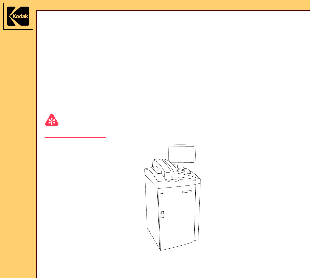
PREVENTIVE MAINTENANCE
for the
Kodak DirectView CR 825/850 SYSTEMS
Service Codes: 5634, 4825
Important
Qualified service personnel must do these procedures.
Publication No. PM4825-1
10DEC05
Supersedes PM4825-1
09JAN04
H177_0500AC
Page 2

PREVENTIVE MAINTENANCE
10DEC05
PM4825-1
Page
2 of 30
PLEASE NOTE The information contained herein is based on the experience and knowledge relating to the
subject matter gained by Eastman Kodak Company prior to publication.
No patent license is granted by this information.
Eastman Kodak Company reserves the right to change this information without notice, and
makes no warranty, express or implied, with respect to this information. Kodak shall not be
liable for any loss or damage, including consequential or special damages, resulting from any
use of this information, even if loss or damage is caused by Kodak’s negligence or other fault.
This equipment includes parts and assemblies sensitive to damage from electrostatic
discharge. Use caution to prevent damage during all service procedures.
Table of Contents
Description Page
Necessary Materials . . . . . . . . . . . . . . . . . . . . . . . . . . . . . . . . . . . . . . . . . . . . 3
Maintenance Plan . . . . . . . . . . . . . . . . . . . . . . . . . . . . . . . . . . . . . . . . . . . . . . 4
Checking the Error Logs . . . . . . . . . . . . . . . . . . . . . . . . . . . . . . . . . . . . . . . . 5
Checking the Scan Operation . . . . . . . . . . . . . . . . . . . . . . . . . . . . . . . . . . . . 5
Cleaning the FILTER - 2.4 GHz PC only . . . . . . . . . . . . . . . . . . . . . . . . . . . . 6
Cleaning the PMT/DAS BOARD . . . . . . . . . . . . . . . . . . . . . . . . . . . . . . . . . . . 7
Cleaning the PMTs and COLLECTOR AY . . . . . . . . . . . . . . . . . . . . . . . . . . 8
Cleaning and Applying Lubricant to the CASSETTE HANDLING AY. . . . 9
Cleaning the BAR CODE READER . . . . . . . . . . . . . . . . . . . . . . . . . . . . . . . . 11
Cleaning the EXTRACTION BAR. . . . . . . . . . . . . . . . . . . . . . . . . . . . . . . . . . 12
Cleaning and Applying Lubricant to the SLOW SCAN SLIDES . . . . . . . . 13
Cleaning the ERASE LAMP AY . . . . . . . . . . . . . . . . . . . . . . . . . . . . . . . . . . . 14
Cleaning the System . . . . . . . . . . . . . . . . . . . . . . . . . . . . . . . . . . . . . . . . . . . . 15
Installing the New LIGHT SEALS on the TOP COVER . . . . . . . . . . . . . . . 16
Installing the New CLAMP BAR PLUSH. . . . . . . . . . . . . . . . . . . . . . . . . . . . 17
Installing the New RIGHT and LEFT LIGHT BAFFLES. . . . . . . . . . . . . . . . 19
Installing the New REAR CLIP AY . . . . . . . . . . . . . . . . . . . . . . . . . . . . . . . . 20
Installing the New LIGHT SEAL PLUSH . . . . . . . . . . . . . . . . . . . . . . . . . . . 21
Installing the New LEAF SPRINGS . . . . . . . . . . . . . . . . . . . . . . . . . . . . . . . . 23
Installing the New FIXED LIGHT SEAL PADDLE . . . . . . . . . . . . . . . . . . . . . 24
Installing the New LIGHT SEAL PADDLE. . . . . . . . . . . . . . . . . . . . . . . . . . . 25
Installing the New CASSETTE DRIVE ROLLERS . . . . . . . . . . . . . . . . . . . . 26
Checking the CAM and MOTOR . . . . . . . . . . . . . . . . . . . . . . . . . . . . . . . . . . 27
Checking the Adjustments. . . . . . . . . . . . . . . . . . . . . . . . . . . . . . . . . . . . . . . 28
Checking the Operation . . . . . . . . . . . . . . . . . . . . . . . . . . . . . . . . . . . . . . . . . 29
Page 3

10DEC05
PM4825-1
Page
3 of 30
PREVENTIVE MAINTENANCE
Necessary Materials
Part No . Description Quantity Notes
--- soap - solution --- Purchase locally
3E0899 soft LINT-FREE CLOTH --- Package of 300
1C8026 LUBRICANT ---
TL-4071 VACUUM CLEANER ---
1C8000 LENS CLEANER --952807 LENS PAPER --- Package of 50
5E6777 SPINDLE OIL --- 4-oz BOTTLE
1C8067 CANNED AIR --- Package of 2
7E7978 PM KIT 1
6E5266 LIGHT SEAL - left 1 Included in PM KIT.
6E5267 LIGHT SEAL - right 1
1F2215 PLUSH - clamp bar 2
1F5142 LIGHT BAFFLE - right 1
1F6140 LIGHT BAFFLE - left 1
1F7859 LIGHT SEAL AY - front 1
1F2941 CLIP AY 1
1F5817 PLUSH - light seal 2
1F6723 SPRING - leaf 3
9F6823 PADDLE - light seal, fixed 1
1F5967 PADDLE - light seal, plush 3
1F5661 ROLLER - cassette drive 2
Page 4

PREVENTIVE MAINTENANCE
10DEC05
PM4825-1
Page
4 of 30
Maintenance Plan
Procedure Do:
Checking the Error Logs Every service call
Checking the Scan Operation Every service call
Cleaning the FILTER - 2.4 GHz PC only Every 6 months
Cleaning the PMT/DAS BOARD Every 6 months
Cleaning the PMTs and COLLECTOR AY Ever y 6 months
Cleaning and Applying Lubricant to the CASSETTE HANDLING AY Every 6 months
Cleaning the BAR CODE READER Every 6 months
Cleaning the EXTRACTION BAR Every 6 months
Cleaning and Applying Lubricant to the SLOW SCAN SLIDES Every 6 months
Cleaning the ERASE LAMP AY Every 6 months
Cleaning the System Every 6 months
Installing the New LIGHT SEALS on the TOP COVER Every 6 months
Installing the New CLAMP BAR PLUSH Every 6 months
Installing the New RIGHT and LEFT LIGHT BAFFLES Every 6 months
Installing the New REAR CLIP AY Every 6 months
Installing the New LIGHT SEAL PLUSH Every 6 months
Installing the New LEAF SPRINGS Every 6 months
Installing the New FIXED LIGHT SEAL PADDLE Every 6 months
Installing the New LIGHT SEAL PADDLE Every 6 months
Installing the New CASSETTE DRIVE ROLLERS Every 6 months
Checking the CAM and MOTOR Every 6 months
Checking the Adjustments Every 6 months
Checking the Operation Every service call
Page 5
PREVENTIVE MAINTENANCE
10DEC05
PM4825-1
Page
5 of 30
Checking the Error Logs
1 Check the Error Logs. See Checking the Error Logs.
Important
If you see more than one error code of the same component or assembly, you might have to
install new parts or do adjustments during this procedure.
2 Do an evaluation of the error logs.
3 Continue with Checking the Scan Operation.
Checking the Scan Operation
Important
You must check the scan operation before de-energizing the system.
1 Observe the scan operation or all CASSETTE sizes and make repairs before doing
preventive maintenance procedures.
2 Is this service call a 6 - month call?
Yes No
Continue with Cleaning the FILTER
- 2.4 GHz PC only.
Advance to Checking the Operation.
Page 6
PREVENTIVE MAINTENANCE
10DEC05
PM4825-1
Page
6 of 30
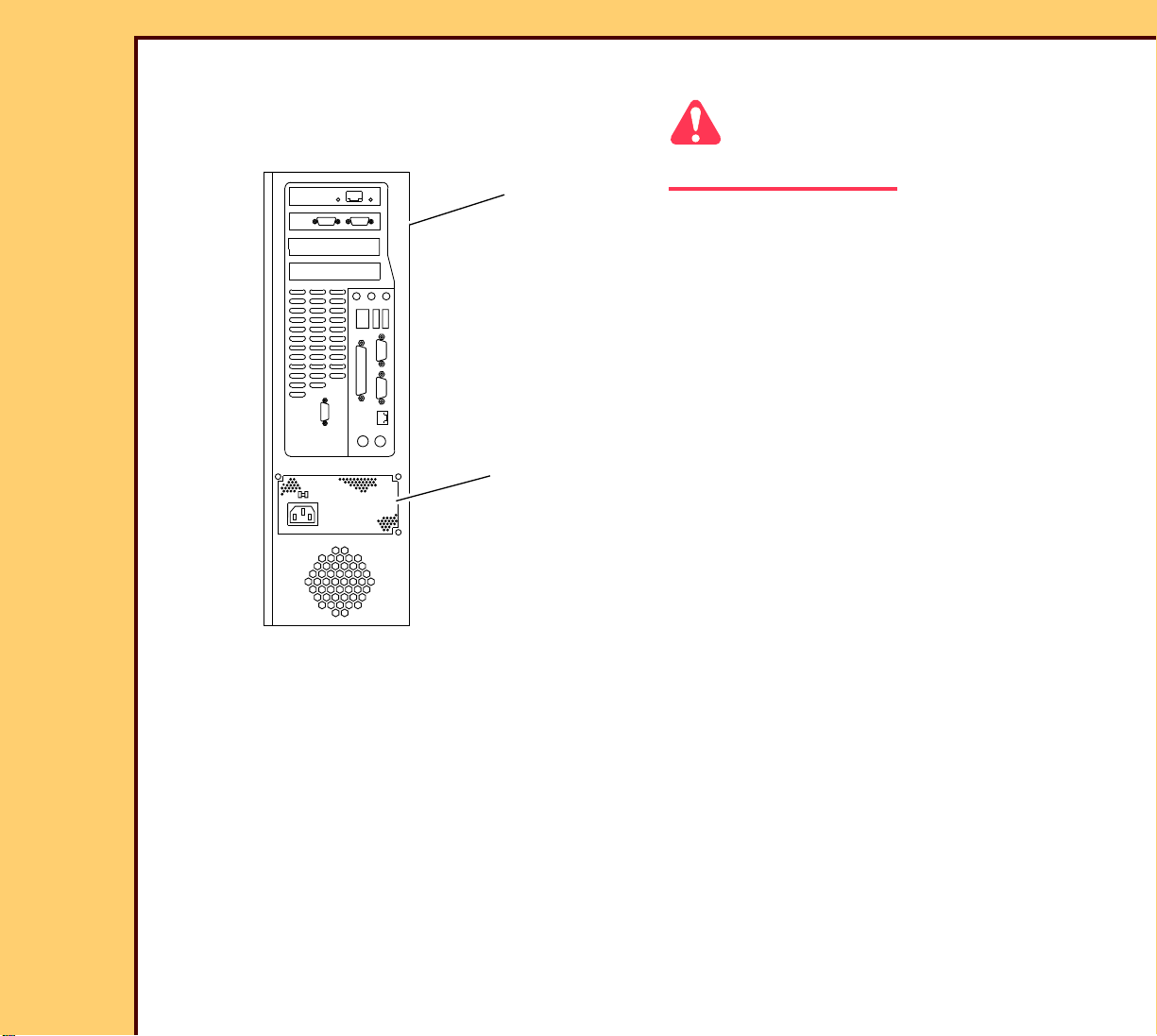
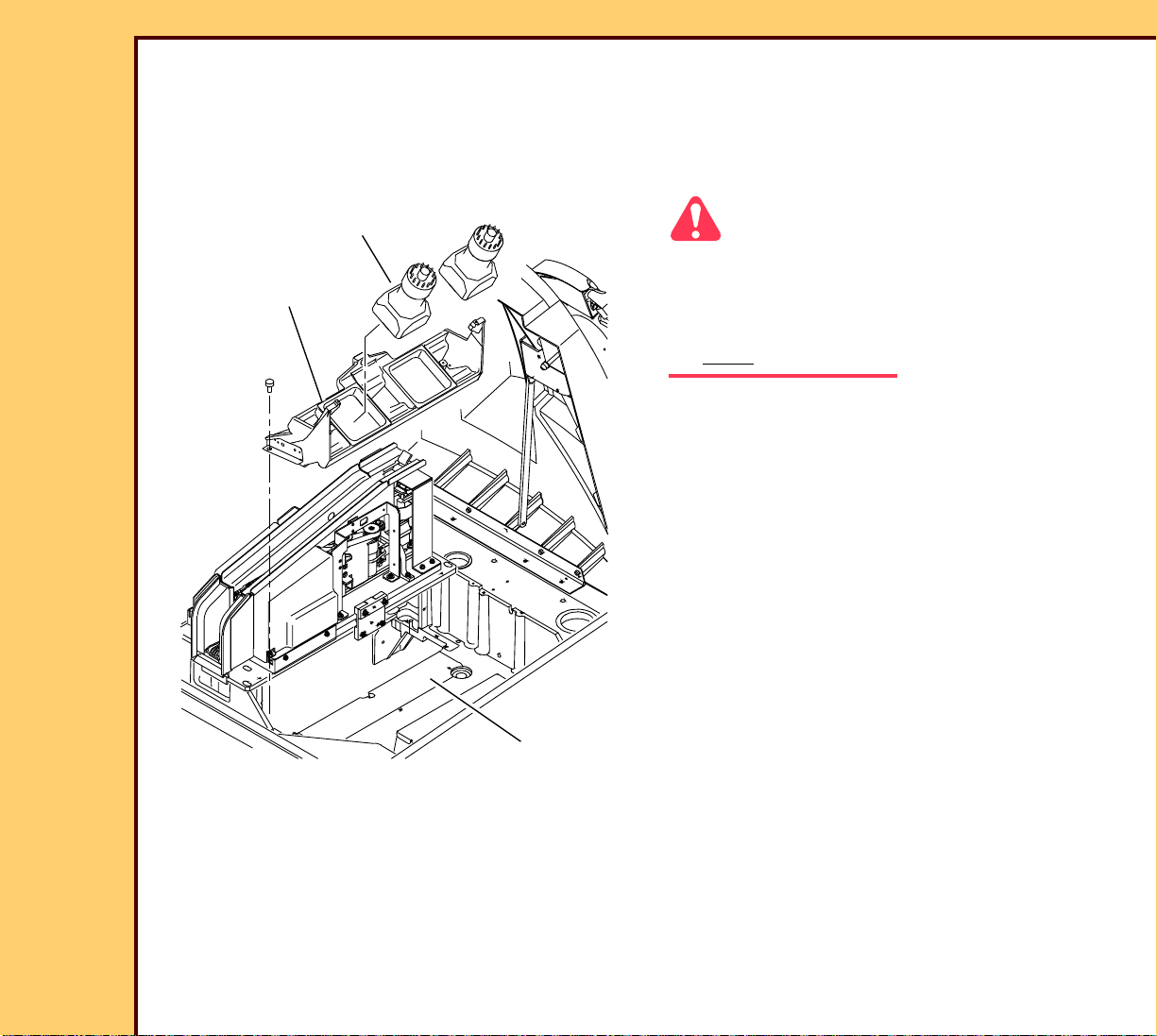
Cleaning the FILTER - 2.4 GHz PC only
2.4 GHz
computer
FILTER
Caution
Dangerous Voltage
1 De-energize the system. See
Energizing the System.
2 Remove the REAR PANEL.
3 Use the VACUUM CLEANER to remove
dust from the FILTER in the computer.
4 Install the REAR PANEL.
5 Continue with Cleaning the PMT/DAS
BOARD.
H194_0029GCA
H194_0029GC
Page 7
PREVENTIVE MAINTENANCE
10DEC05
PM4825-1
Page
7 of 30
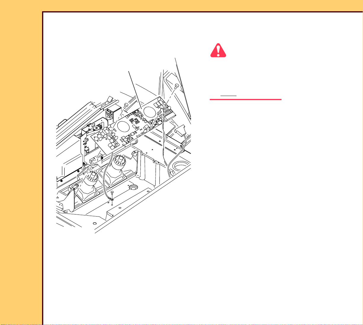
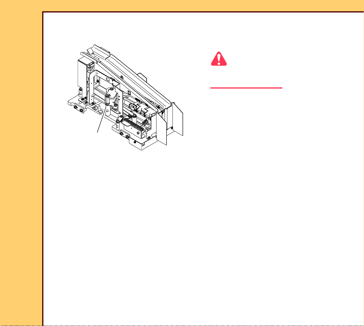
Cleaning the PMT/DAS BOARD
PMT/DAS BOARD
1 Remove the PMT/DAS BOARD.
Caution
• Use the VACUUM CLEANER to remove
dust before using the CANNED AIR.
• Use the CANNED AIR to move debris
away from the OPTICAL CAVITY.
2 Use the VACUUM CLEANER to remove
dust from the PMT/DAS BOARD.
3 If necessary, use the CANNED AIR
1C8067 to remove dust from the PMT/
DAS BOARD.
4 Continue with Cleaning the PMTs and
COLLECTOR AY.
H194_1076GCA
H194_1076GC
Page 8
10DEC05
PM4825-1
Page
8 of 30
PREVENTIVE MAINTENANCE
Cleaning the PMTs and COLLECTOR AY
1 If necessary remove the PMT/DAS BOARD.
2 Remove the PMTs and COLLECTOR AY.
COLLECTOR AY
H194_1077GCA
H194_1077GC
2 PMTs
OPTICAL
CAVITY
Caution
• Use the VACUUM CLEANER to remove
dust before using the CANNED AIR.
• Use the CANNED AIR to move debris
away from the OPTICAL CAVITY.
3 Use the VACUUM CLEANER to remove
dust from:
• 2 PMTs
• COLLECTOR AY
• OPTICAL CAVITY
4 If necessary, use the CANNED AIR to
remove dust from:
• 2 PMTs
• COLLECTOR AY
• OPTICAL CAVITY
5 Install:
• PMTs and COLLECTOR AY
• PMT/DAS BOARD
6 Continue with Cleaning and Applying
Lubricant to the CASSETTE
HANDLING AY.
Page 9
PREVENTIVE MAINTENANCE
10DEC05
PM4825-1
Page
9 of 30
Cleaning and Applying Lubricant to the CASSETTE HANDLING AY
1 Remove the CASSETTE HANDLING
AY.
Caution
Use the VACUUM CLEANER to remove
dust before using the CANNED AIR.
2 Use the VACUUM CLEANER to remove
dust from the CASSETTE HANDLING
AY.
3 If necessary, use the CANNED AIR to
CASSETTE
HANDLING AY
H194_1078ACA
H194_1078AC
remove dust from the CASSETTE
HANDLING AY.
Page 10

10DEC05
PM4825-1
Page
10 of 30
PREVENTIVE MAINTENANCE
DRIVE
ROLLER AY
CAM BLOCK
STOP PIN
LEFT LIGHT
SEAL AY
STOP PIN
4 Apply lubricant to:
• STOP PIN for the RIGHT LIGHT SEAL AY
• STOP PIN for the LEFT LIGHT SEAL AY
• CAM BLOCK for the FRONT LIGHT SEAL
• CAM BLOCK for the DRIVE ROLLER AY
5 Continue with Cleaning the BAR CODE READER.
CAM BLOCK
FRONT LIGHT SEAL
RIGHT LIGHT
SEAL AY
H194_1079HCA
H194_1079HC
Page 11

PREVENTIVE MAINTENANCE
10DEC05
PM4825-1
Page
11 of 30
Cleaning the BAR CODE READER
1 If necessary, remove the CASSETTE
HANDLING AY.
Caution
Use the VACUUM CLEANER to remove
dust before using the CANNED AIR.
2 Use the VACUUM CLEANER to remove
dust from the BAR CODE READER.
3 If necessary, use the CANNED AIR to
remove the dust from the BAR CODE
BAR CODE
READER
H194_1080ACA
H194_1080AC
4 If the CANNED AIR does not remove the contamination from the BAR CODE READER,
clean the BAR CODE READER with:
READER.
• LENS CLEANER SOLUTION 1C8000
• LENS PAPER 952807
5 Continue with Cleaning the EXTRACTION BAR .
Page 12

PREVENTIVE MAINTENANCE
10DEC05
PM4825-1
Page
12 of 30
Cleaning the EXTRACTION BAR
EXTRACTION BAR
H194_1081ACA
H194_1081AC
1 If necessary, remove the CASSETTE
HANDLING AY.
Caution
Use the VACUUM CLEANER to remove
dust before using the CANNED AIR.
2 Clean the EXTRACTION BAR with a
LINT-FREE CLOTH.
3 Install the CASSETTE HANDLING AY.
4 Continue with Cleaning and Applying
Lubricant to the SLOW SCAN
SLIDES.
Page 13

PREVENTIVE MAINTENANCE
10DEC05
PM4825-1
Page
13 of 30
Cleaning and Applying Lubricant to the SLOW SCAN SLIDES
EXTRACTION BAR
SLOW SCAN
SLIDES
SLOW SCAN AY
H194_1082BCA
H194_1082BC
1 Use a LINT-FREE CLOTH to clean:
• SLOW SCAN SLIDES
• top of the EXTRACTION BAR
LEAD
SCREW
holes
CARRIAGE
Caution
Do not apply SPINDLE OIL on the LEAD SCREW.
2 Apply 2 drops of SPINDLE OIL on each of the 2 SLOW SCAN SLIDES.
3 Rotate the LEAD SCREW up and down to apply the lubricant.
4 Apply 2 drops of SPINDLE OIL in the holes on the CARRIAGE.
5 Continue with Cleaning the ERASE LAMP AY.
Page 14

PREVENTIVE MAINTENANCE
10DEC05
PM4825-1
Page
14 of 30
Cleaning the ERASE LAMP AY
LATCH
4512 435
ERASE
LAMPS
1 Disengage the LATCH.
2 Pull the ERASE LAMP AY.
3 Use a LINT-FREE CLOTH to clean
ERASE LAMPS.
4 Use the VACUUM CLEANER to remove
dust from the ERASE LAMP AY.
5 If necessary, use the CANNED AIR to
remove the dust from the ERASE LAMP
AY.
6 Continue with Cleaning the System.
H177_2104GCB
H177_2104GC
ERASE
LAMP AY
Page 15

PREVENTIVE MAINTENANCE
10DEC05
PM4825-1
Page
15 of 30
Cleaning the System
Caution
Dangerous Voltage
1 De-energize the system. See Energizing the System.
2 Use the VACUUM CLEANER to remove dust from the inside of the system.
3 Continue with Installing the New LIGHT SEALS on the TOP COVER.
Page 16

PREVENTIVE MAINTENANCE
10DEC05
PM4825-1
Page
16 of 30
Installing the New LIGHT SEALS on the TOP COVER
TOP COVER
1 Open the TOP COVER.
Important
• The narrow end of the LIGHT SEAL must be toward the front edge of the SLOT.
narrow ends of
LIGHT SEALS
LEFT
LIGHT
SEAL
RIGHT
LIGHT
SEAL
Top View
front edge of SLOT
back edge of SLOT
H194_1083BCA
H194_1083BC
• The LIGHT SEAL must make a seal against the back edge of the SLOT.
2 Remove:
• LEFT LIGHT SEAL - discard
• RIGHT LIGHT SEAL - discard
3 Install the new:
• LEFT LIGHT SEAL
• RIGHT LIGHT SEAL
4 Continue with Installing the New CLAMP BAR PLUSH.
Page 17

PREVENTIVE MAINTENANCE
10DEC05
PM4825-1
Page
17 of 30
Installing the New CLAMP BAR PLUSH
LEFT CASSETTE GUIDE
RIGHT CASSETTE GUIDE
4 SCREWS
2 COVERS
2 SCREWS
1 Remove:
• 2 COVERS
• 4 SCREWS
• LEFT CASSETTE GUIDE
• RIGHT CASSETTE GUIDE
• 2 SCREWS
• CASSETTE LOAD CRADLE
H194_1062GCA
H194_1062GC
CASSETTE
LOAD CRADLE
Page 18

10DEC05
PM4825-1
Page
18 of 30
PREVENTIVE MAINTENANCE
CLAMP BAR PLUSH
CLAMP BAR
2 SCREWS
2 Remove:
• 2 SCREWS
• CLAMP BAR PLUSH
3 Install:
• new CLAMP BAR PLUSH
• 2 SCREWS
4 Reverse Step 1.
5 Continue with Installing the New
RIGHT and LEFT LIGHT BAFFLES.
H194_1084GCA
H194_1084GC
Page 19

PREVENTIVE MAINTENANCE
10DEC05
PM4825-1
Page
19 of 30
Installing the New RIGHT and LEFT LIGHT BAFFLES
1 Remove:
• 2 SCREWS
CASSETTE
LOAD CRADLE
2 SCREWS
LEFT LIGHT
BAFFLE
2 SCREWS
H194_1074ACA
H194_1074AC
2 SCREWS
• CASSETTE LOAD CRADLE
2 Remove:
• 2 SCREWS
• LEFT LIGHT BAFFLE - discard
H194_1085ACA
H194_1085AC
RIGHT LIGHT
BAFFLE
CASSETTE
LOAD CRADLE
• 2 SCREWS
• RIGHT LIGHT BAFFLE - discard
3 Install:
• new LEFT LIGHT BAFFLE
• 2 SCREWS
• new RIGHT LIGHT BAFFLE
• 2 SCREWS
4 Reverse Step 1.
5 Continue with Installing the New
REAR CLIP AY.
Page 20

10DEC05
PM4825-1
Page
20 of 30
PREVENTIVE MAINTENANCE
Installing the New REAR CLIP AY
1 Open the TOP COVER.
2 Remove:
REAR BRACKET AY
4 SCREWS
REAR CLIP AY
H194_1086GCA
H194_1086GC
• 4 SCREWS
• REAR BRACKET AY
3 Remove:
• 2 SCREWS
• REAR CLIP AY - discard
2 SCREWS
H194_1087ACA
H194_1087AC
4 Install:
• new REAR CLIP AY
• 2 SCREWS
5 Reverse Step 2.
6 Continue with Installing the New
LIGHT SEAL PLUSH.
Page 21

10DEC05
PM4825-1
Page
21 of 30
PREVENTIVE MAINTENANCE
Installing the New LIGHT SEAL PLUSH
LEFT CASSETTE GUIDE
RIGHT CASSETTE GUIDE
4 SCREWS
2 COVERS
2 SCREWS
1 Remove:
• 2 COVERS
• 4 SCREWS
• LEFT CASSETTE GUIDE
• RIGHT CASSETTE GUIDE
• 2 SCREWS
• CASSETTE LOAD CRADLE
H194_1062GCA
H194_1062GC
CASSETTE
LOAD CRADLE
Page 22

10DEC05
PM4825-1
Page
22 of 30
PREVENTIVE MAINTENANCE
2 Remove:
• 2 SCREWS
• RIGHT PLUSH PADDLE AY
• 2 SCREWS
• LIGHT SEAL PLUSH
3 Install:
• new LIGHT SEAL PLUSH
• 2 SCREWS
• RIGHT PLUSH PADDLE AY
2 SCREWS
H194_1088GCA
H194_1088GC
LIGHT SEAL
PLUSH
RIGHT PLUSH
PADDLE AY
2 SCREWS
• 2 SCREWS
4 Reverse Step 1.
5 Continue with Installing the New LEAF
SPRINGS.
Page 23

PREVENTIVE MAINTENANCE
10DEC05
PM4825-1
Page
23 of 30
Installing the New LEAF SPRINGS
1 Remove:
• 3 SCREWS
• 3 LEAF SPRINGS - discard
2 Install:
• 3 new LEAF SPRINGS
• 3 SCREWS
3 Continue with Installing the New
FIXED LIGHT SEAL PADDLE.
3 SCREWS
3 LEAF
SPRINGS
H194_1090GCA
H194_1090GC
Page 24

PREVENTIVE MAINTENANCE
10DEC05
PM4825-1
Page
24 of 30
Installing the New FIXED LIGHT SEAL PADDLE
1 Remove:
• 2 SCREWS
• FIXED LIGHT SEAL PADDLE -
discard
2 Install:
• new FIXED LIGHT SEAL PADDLE
• 2 SCREWS
3 Continue with Installing the New
LIGHT SEAL PADDLE.
2 SCREWS
FIXED LIGHT
SEAL PADDLE
H194_1091GCA
H194_1091GC
Page 25

PREVENTIVE MAINTENANCE
10DEC05
PM4825-1
Page
25 of 30
Installing the New LIGHT SEAL PADDLE
RIGHT PLUSH
3 SCREWS
3 LIGHT SEAL
PADDLES
PADDLE AY
1 Remove:
• 3 SCREWS
• 3 LIGHT SEAL PADDLES - discard
2 Install:
• 3 new LIGHT SEAL PADDLES
PLUSH
• 3 SCREWS
• RIGHT PLUSH PADDLE AY
• 2 SCREWS
3 Continue with Installing the New
CASSETTE DRIVE ROLLERS.
H194_1092GCA
H194_1092GC
2 SCREWS
Page 26

PREVENTIVE MAINTENANCE
10DEC05
PM4825-1
Page
26 of 30
Installing the New CASSETTE DRIVE ROLLERS
1 Remove the CASSETTE DRIVE AY.
E-RING
WASHER
PULLEY
BUSHING
SHAFT
PIN
2 PINS
BELT
2 E-RINGS
PULLEY
2 SETSCREWS
CASSETTE
CASSETTE
DRIVE AY
DRIVE AY
MOTOR
BUSHING
2 Remove and discard the 2 CASSETTE
DRIVE ROLLERS.
3 Install:
• 2 new CASSETTE DRIVE
ROLLERS
• CASSETTE DRIVE AY
4 Continue with Checking the CAM and
MOTOR.
2 CASSETTE
2 CASSETTE
DRIVE ROLLERS
DRIVE ROLLERS
H194_1007GCA
H194_1007GCB
H194_1007GC
H194_1007GC
Page 27

PREVENTIVE MAINTENANCE
10DEC05
PM4825-1
Page
27 of 30
Checking the CAM and MOTOR
MOTOR
SHAFT
CAM
H177_3031ACA
H177_3031AC
1 Remove the CAM MOTOR AY.
2 Pull the CAM toward the MOTOR.Check
that the CAM does not move on the
SHAFT of the MOTOR by pulling to
CAM toward the MOTOR.
3 Does the CAM move on the SHAFT?
Yes No
Install new CAM
MOTOR AY.
Continue with Step
4.
4 Install the CAM MOTOR AY.
5 Continue with Checking the
Adjustments.
Page 28

PREVENTIVE MAINTENANCE
10DEC05
PM4825-1
Page
28 of 30
Checking the Adjustments
1 Do:
• GALVO BOARD
• GALVO ROTATION
• FOLD MIRROR
• COLLECTOR AY
• INTERMEDIATE PLATE
• CAM SENSOR BOARD A8
• CAM MOTOR AY
• SLED CAM FOLLOWER
• CLAMP BAR
• CASSETTE END STOP
• REAR CASSETTE SENSOR
• EXTRACTION BAR HOME POSITION
• PLATE POSITIONING AY
• RIGHT and LEFT PLUSH AY - Alignment
• LEFT PLUSH AY - Vertical Position
• INTERNAL BAR CODE READER
• CASSETTE LOAD CRADLE
2 Continue with Checking the Operation.
Page 29

PREVENTIVE MAINTENANCE
10DEC05
PM4825-1
Page
29 of 30
Checking the Operation
1 Do:
• Setting the Laser Calibration Voltage
• Calibration for the CR 825/850 SYSTEM
• Checking the Operation
Page 30

PREVENTIVE MAINTENANCE
10DEC05
PM4825-1
Page
30 of 30
Publication History
Publication
Date
Publication
No.
ECO No.
Changed
Pages
File Name Notes
09JAN04 pm4825-1 ---- - - - pm4825_1.fm New Publication
10DEC05 pm4825-1 ---- 3,6 pm4825_1.fm Revised
Kodak and DirectView are trademarks of Eastman Kodak Company.
Printed in U.S.A. • pm4825_1.fm
EASTMAN KODAK COMPANY
Rochester, NY 14650
HEALTH GROUP
 Loading...