

Page 1

KIA, THE COMPANY
Now that you are the owner of a Kia vehicle, you’ll probably be asked a lot of questions about your vehicle and the company like “What
is a Kia?”, “Who is Kia?”, “What does ‘Kia’ mean?”.
Here are some answers. First, Kia is the oldest car company in Korea. It’s a company that has thousands of employees focused on
building high-quality vehicles at affordable prices because the employees own a significant percentage of the company.
The first syllable, Ki, in the word “Kia” means “to arise from to the world” or “to come up out of to the world”. The second syllable, a,
means “Asia”. So, the word Kia, means “to arise from” or “to come up out of Asia to the world”.
Enjoy your vehicle!
Page 2
FOREWORD
Thank you for choosing a Kia vehicle.
When you require service, remember that your authorized Kia
dealer knows your vehicle best. Your dealer has factory-trained
technicians, recommended special tools, genuine Kia replacement
parts, and is dedicated to your complete satisfaction.
Because subsequent owners require this important information as
well, this publication should remain with the vehicle if it is sold.
This manual covers all MAGENTIS models and will familiarize
you with operation, maintenance and safety information about
your new vehicle. It is supplemented by a Warranty and
Consumer Information Manual that provides important
information on all warranties regarding your vehicle. We urge
you to read these publications carefully and follow the
recommendations to help assure enjoyable and safe operation of
your new vehicle.
Kia offers a great variety of options, components and features for
its various models.
Therefore, the equipment described in this manual, along with the
various illustrations, may not all be applicable to your particular
vehicle. The information and specifications included in this
manual were accurate at the time of printing. Kia Motors reserves
the right to discontinue or change specifications or design at any
time without notice and without incurring any obligation. If you
have questions, always check with your Kia Dealer.
We assure you of our continuing interest in your motoring
pleasure and satisfaction in your Kia vehicle.
©2005 Kia Motors Corp.
All rights reserved. Reproduction by any means, electronic or
mechanical, including photocopying, recording, or by any
information storage and retrieval system or translation in whole or
part is not permitted without written authorization from Kia
Motors Corporation.
Printed in Korea
CAUTION
Severe engine and transaxle damage may result from the
use of poor quality fuels and lubricants that do not meet
Kia specification. You must always use high quality fuels
and lubricants that meet the specifications listed on page 735 in the Maintenance section and page 5-2 in the Driving
tips section of the Owner’s Manual.
i
Page 3
TABLE OF CONTENTS
INTRODUCTION
YOUR VEHICLE AT A GLANCE
KNOWING YOUR VEHICLE
DRIVING YOUR VEHICLE
DRIVING TIPS
IN CASE OF AN EMERGENCY
MAINTENANCE
SPECIFICATIONS
INDEX
1
2
3
4
5
6
7
8
9
ii
Page 4

INTRODUCTION
How To Use This Manual . . . . . . . . . . . . . . . . . . . . . . . .1-2
Vehicle Break-In Process . . . . . . . . . . . . . . . . . . . . . . . .1-3
1
1-1
Page 5
INTRODUCTION
HOW TO USE THIS MANUAL
We want to help you get the greatest
possible driving pleasure from your
vehicle. Your Owner’s Manual can
assist you in many ways. We strongly
urge you to review the entire manual.
However, in order to prevent death or
injuries, at the very least, you must
review the WARNING and CAUTION
sections spread throughout the manual,
which are easily recognized by their
special markings indicated below.
Illustrations complement the words in
this manual to help explain the best
way to enjoy your vehicle. By reading
your manual, you can find out about
features, important safety information,
and driving under various road
conditions.
The layout of the manual is provided in
the Table of Contents.
Index: A good place to start is the
index; it has an alphabetical listing of
all information in your manual.
Sections: This manual has eight
sections plus an index. Each begins
with a brief list of contents so you can
tell at a glance if that section has the
information you want.
You’ll find various WARNINGs,
CAUTIONs, and NOTICEs in this
manual. These WARNINGs, CAUTIONs
and NOTICEs were prepared to enhance
your personal safety and continued
satisfaction with your Kia vehicle. You
should carefully read and follow ALL
procedures and recommendations
provided in these WARNINGs,
CAUTIONs and NOTICEs.
WARNING
A WARNING indicates a
situation in which serious
bodily injury or death could
result if the warning is
ignored.
CAUTION
A CAUTION indicates a situation
in which personal injury, perhaps
severe, could result if the caution
is ignored.
✻ NOTICE
A NOTICE indicates a situation in
which damage to your vehicle
could result if the notice is
ignored.
1-2
Page 6

VEHICLE BREAK-IN
PROCESS
No special break-in period is needed.
By following a few simple precautions
for the first 1,000 km (600 miles) you
may add to the performance, economy
and life of your vehicle.
• Do not race the engine.
• Do not maintain a single speed for
long periods of time, either fast or
slow. Varying engine speeds are
beneficial for proper engine break-in.
• Avoid hard stops, except in
emergencies, to allow the brakes to
seat properly.
• Avoid full-throttle starts.
1-3
Page 7

YOUR VEHICLE AT A GLANCE
Interior and Exterior Overview . . . . . . . . . . . . . . . . . . . .2-2
Instrument Panel Overview . . . . . . . . . . . . . . . . . . . . . . .2-3
2
2-1
Page 8
YOUR VEHICLE AT A GLANCE
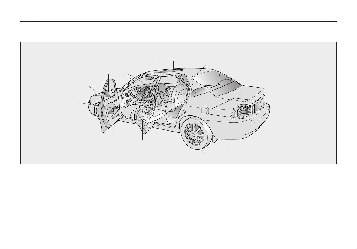
INTERIOR AND EXTERIOR OVERVIEW
10
1. Rearview mirror
2. Sunvisor
3. Sunroof (If Equipped)
4. Seat
5. Spare tire
2-2
11
12
3
8
13
2
1
9
6. Tail-lights
7. Fuel filler lid
8. Parking brake
9. Rear door child safety lock
10. Power window switches
4
5
6
7
MMSA2001
11. Door
12. Outside rearview mirror
13. Air bags
Page 9
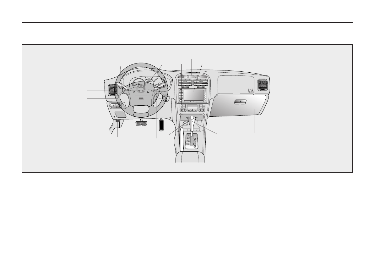
INSTRUMENT PANEL OVERVIEW
R
E
S
AC
C
E
L
CA
N
C
E
L
C
O
A
S
T
S
E
T
1. Instrument cluster
2. Air bag
3. Climate control
4. Clock
5. Radio (If Equipped)
15
4
3
5
14
1
2
7
7
6
13
12
11
9
8
10
MMSA2002
6. Air bag
7. Vent
8. Glove box
9. Shift lever (Automatic)
10. Parking brake
11. Wiper/Washer
12. Power outlet
13. Hood release
14. Light control/Turn signals
15. Steering wheel
2-3
Page 10

KNOWING YOUR VEHICLE
Keys . . . . . . . . . . . . . . . . . . . . . . . . . . . . . . . . . . . . . . . . . 3-3
Keyless Entry System . . . . . . . . . . . . . . . . . . . . . . . . . . . 3-4
Theft-Alarm System. . . . . . . . . . . . . . . . . . . . . . . . . . . . . 3-5
Immobilizer System. . . . . . . . . . . . . . . . . . . . . . . . . . . . . 3-6
Door Locks. . . . . . . . . . . . . . . . . . . . . . . . . . . . . . . . . . . . 3-9
Windows. . . . . . . . . . . . . . . . . . . . . . . . . . . . . . . . . . . . . 3-11
Seats . . . . . . . . . . . . . . . . . . . . . . . . . . . . . . . . . . . . . . . . 3-14
Safety Belts . . . . . . . . . . . . . . . . . . . . . . . . . . . . . . . . . . 3-22
Air Bag - Supplemental Restraint System. . . . . . . . . . 3-42
Trunk Lid . . . . . . . . . . . . . . . . . . . . . . . . . . . . . . . . . . . . 3-52
Hood . . . . . . . . . . . . . . . . . . . . . . . . . . . . . . . . . . . . . . . . 3-54
Fuel Filler Lid . . . . . . . . . . . . . . . . . . . . . . . . . . . . . . . . . 3-55
Steering Wheel. . . . . . . . . . . . . . . . . . . . . . . . . . . . . . . . 3-58
Mirrors . . . . . . . . . . . . . . . . . . . . . . . . . . . . . . . . . . . . . . 3-58
Interior Lights. . . . . . . . . . . . . . . . . . . . . . . . . . . . . . . . . 3-62
Cup Holders and Console Storage Compartment . . . 3-63
3
3-1
Page 11

KNOWING YOUR VEHICLE
Sunglass Holder . . . . . . . . . . . . . . . . . . . . . . . . . . . . . . 3-64
Sunroof. . . . . . . . . . . . . . . . . . . . . . . . . . . . . . . . . . . . . . 3-65
Antenna . . . . . . . . . . . . . . . . . . . . . . . . . . . . . . . . . . . . . 3-68
Luggage Net. . . . . . . . . . . . . . . . . . . . . . . . . . . . . . . . . . 3-69
3-2
Page 12
KEYS
➡➡
50063
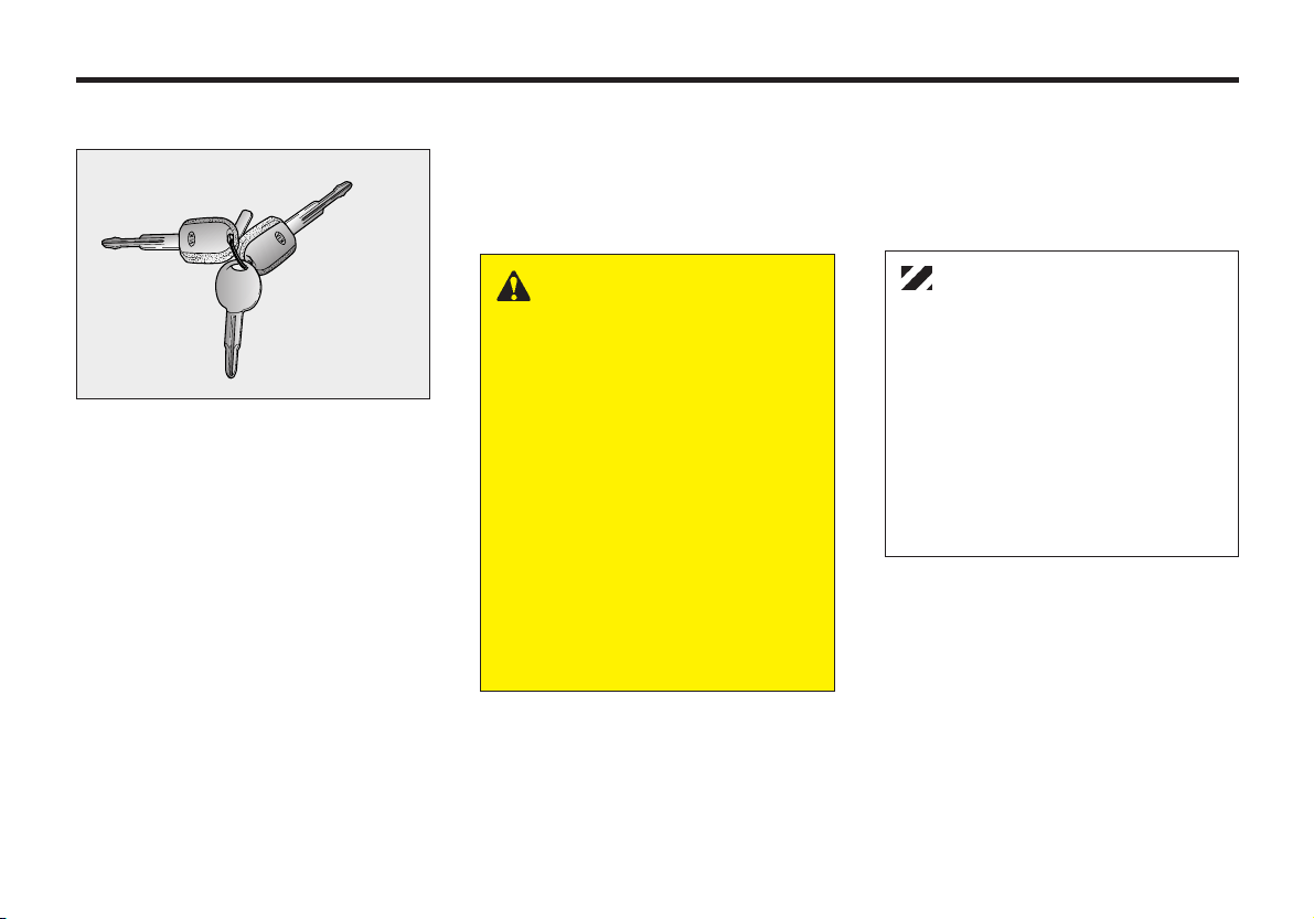
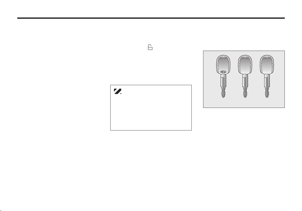
Your vehicle has two master keys and a
sub key. The master key will open all
locks on your vehicle.
The sub key will only function in the
ignition and the door locks.
Leaving your sub key with a parking
attendant will ensure that your vehicle’s
trunk, trunk lid release, glove box
compartment and rear trunk access may
not be unlocked in your absence.
MMSA3070
The key number is stamped into the plate
attached to the key set. If you should lose
your keys, this number will enable an
Authorized Kia Dealer to duplicate the
keys easily. Remove the plate and store it
in a safe place. Also, record the number
and keep it in a safe and handy place, but
not in the vehicle.
WARNING - Ignition Key
Leaving children unattended in
a vehicle with the ignition key is
dangerous even if the key is not
in the ignition. Children copy
adults and they could place the
key in the ignition. The ignition
key would enable children to
operate power windows or
other controls, or even make
the vehicle move which could
result in serious bodily injury or
even death. Never leave the
keys in your vehicle with
unsupervised children.
CAUTION
Use only Kia original parts for the
ignition key in your vehicle. If an
aftermarket key is used, the
ignition switch may not return to
ON after START. If this happens,
the starter will continue to operate
causing damage to the starter
motor and possible fire due to
excessive current in the wiring.
3-3
Page 13
KNOWING YOUR VEHICLE
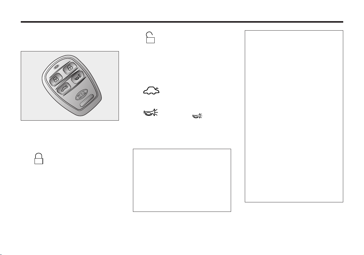
KEYLESS ENTRY SYSTEM
(IF EQUIPPED)
MMSA3067
You can also lock or unlock the door and
open the trunk from the outside with the
transmitter.
• To lock the door, depress
this button. (Hazard
warning light is turned on
and turned off for about 1
second.)
• If you depress the
corresponding button
once, only the driver’s
door will unlock. If you
depress the corresponding
button twice, all four doors
and rear hatch will unlock.
• To open the trunk, depress
this button.
• If you depress the panic
button ( ) on the
transmitter, the horn will
sounds and hazard lamp
will flash.
✻ NOTICE
• The transmitter will not work
under the following conditions :
- Ignition key is in the ignition
key hole.
- The battery of transmitter is
discharged.
• The operational distance(5m) is
exceeded.
• The transmitter may not operate
when the weather is very cold or
when there are other vehicles or
objects around the vehicle.
When the transmitter does not
work correctly, open and close
the door with the ignition key.
• If you have a problem with the
transmitter, contact an
Authorized Kia Dealer.
• Always use the transmitter to
lock/unlock the doors. When the
system is armed the alarm will
sound if you unlock the driver or
passengers door with the
ignition key. If at any time you
have the ignition key in the on
position for more than 30
seconds the system will
deactivate if previously armed.
3-4
Page 14
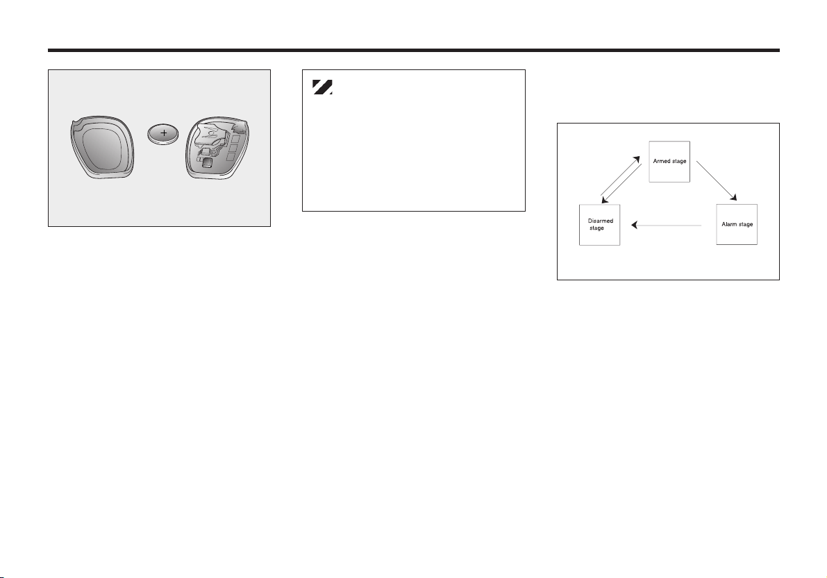
MMSA3068
BATTERY REPLACEMENT
The transmitter uses a 3-Volt, lithiumtype battery. The battery will normally
last for several years. If it ever needs
replacement, use the following
procedure:
1. Using a screwdriver, loosen the
screw on the back of the transmitter
and pry the back off with a thin tool.
2. Remove the battery from the back.
3. Insert a new battery, making sure the
“Plus(+)” side faces up, and
reassemble the transmitter.
CAUTION
Using an incorrect battery can
cause the transmitter to
malfunction. Make sure the
replacement battery has the same
specification as the battery it
replaces.
THEFT - ALARM SYSTEM
(IF EQUIPPED)
HMR.082
ARMED STAGE
The system is armed as described
below.
• After all vehicle doors such as the
engine hood, trunk and passenger
doors are closed, when the
transmitter “Lock” button is pressed,
the doors are locked and the vehicle’s
hazard warning light blinks once. (At
this time, the alarm does not sound.)
3-5
Page 15
KNOWING YOUR VEHICLE
Alarm stage
The alarm will be activated as described
below under the armed stage.
• The door is opened without using the
key or the transmitter.
• The trunk lid is opened without using
the key.
• The engine hood is opened. The
alarm siren will come ON for 30
seconds and then shut OFF for 10
seconds, repeating this cycle two
more times. The engine will not start
during the alarm stage.
Withheld alarm
When the system is armed, the alarm
will not sound if the trunk lid is opened
by the ignition key or the transmitter.
Disarmed stage
The alarm will be released as described
below.
• When the “ ” button in the
transmitter is depressed.
• When the ignition key is in the “ON”
position for 30 seconds or more.
• When you lock/unlock the door with
the ignition key.
CAUTION
If the key is in the ignition the
transmitter will not lock/unlock the
vehicle.
Avoid trying to start the engine
with the alarm activated.
IMMOBILIZER SYSTEM
(IF EQUIPPED)
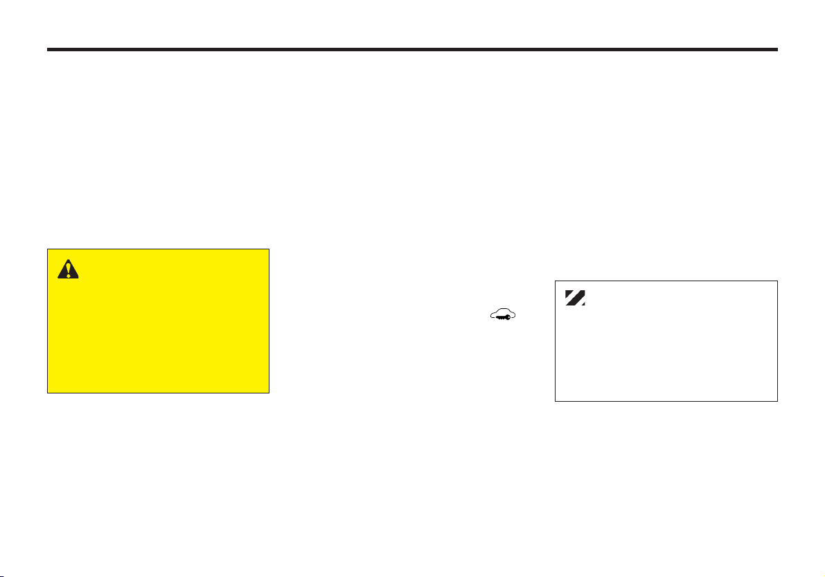
THREE TYPES OF KEYS
SM
ID Key Sub Key Master Key
For convenience, your vehicle has three
types of keys as shown in the illustration.
1) ID key
This key must be used first to register
a unique ID code in the ICM
(Immobilizer Control Module).
2) Master key
This key is for general use. It will
open all locks on your vehicle. One
side of the key has the Kia logo and
the other side has the “M” symbol.
EMSB302
3-6
Page 16
3) Sub key
Similar to the master key, this key
will only function in the ignition and
the door locks, but it will not operate
the trunk and the glove box.
One side of the key has the Kia logo
and the other side has the “S”
symbol.
CAUTION
Don’t lose your ID key or forget the
password.
Always keep your ID key in a place
where you remember and record
your password. If you don’t have
both the password and ID key,
consult your authorized Kia dealer.
IMMOBILIZER SYSTEM
Your vehicle is equipped with an
electronic engine immobilizer system to
reduce the risk of unauthorized vehicle
use.
Your immobilizer system is comprised
of a small transponder in the ignition
key, and antenna coil in the key cylinder
and IU (Immobilizer Unit) in the
instrument panel.
With this system, whenever you insert
your ignition key into the ignition switch
and turn it to ON, the antenna coil in the
ignition switch receives a signal from the
transponder in the ignition key and then
sends the signal to the IU (Immobilizer
Unit).
The IU (Immobilizer Unit) checks the
signal and determines whether the
ignition key is valid.
If the key is determined to be valid, the
engine will start.
If the key is determined to be invalid, the
engine will not start.
To deactivate the immobilizer system:
Insert the ignition key into the key
cylinder and turn it to the ON position.
To activate the immobilizer system:
Turn the ignition key to the OFF
position. The immobilizer system
activates automatically. Without a valid
ignition key for your vehicle, the engine
will not start.
✻ NOTICE
When starting the engine, do not
use the key with other immobilizer
keys around. Otherwise the engine
may not start or may stop soon
after it starts. Keep each key
separately not to have any
malfunction after you receive your
new vehicle.
3-7
Page 17
KNOWING YOUR VEHICLE
This device complies with Industry
Canada Standard RSS-210. Operation
is subject to the following two
conditions:
1. This device may not cause
interference, and
2. This device must accept any
interference, including interference
that may cause undesired operation of
the device.
WARNING
Changes or modifications not
expressly approved by the
party responsible for
compliance could void the
user's authority to operate the
equipment.
3-8
LIMP HOME (OVERRIDE)
PROCEDURE
When you turn the ignition key to the
ON position, if the IMMO indicator
remains on continuously after blinking 6
times, your transponder equipped in the
ignition key is out of order. You cannot
start the engine without the lime home
procedure. To start the engine, you have
to input your password by using the
ignition switch.
The following procedure is how to input
your password of “2345” as an example.
1. Turn the ignition key to the ON
position. The IMMO indicator ( )
will blink 6 times and remain on
indicating the beginning of the limp
home procedure.
2. Turn the ignition key to the ACC
position.
3. To enter the first digit (in this example
“2”), turn the ignition key to the ON
and ACC position twice. Perform the
same procedure for the next digits
between 3 seconds and 10 seconds
(for example, for “3”, turn the ignition
ON and ACC 3 times).
4. If all of the digits have been input
successfully, you have to start the
engine within 10 seconds. If you
attempt to start the engine after 10
seconds, the engine will not start and
you will have to input your password
again.
After performing the limp home
procedure, you have to see an authorized
Kia dealer immediately to inspect and
repair your ignition key or immobilizer
system.
CAUTION
If you cannot start your engine in
spite of limp home procedure, have
your vehicle towed by an
authorized Kia dealer for
inspection and necessary repairs.
Page 18
CAUTION
The transponder in your ignition
key is an important part of the
immobilizer system. It is designed
to give years of trouble free service,
however you should avoid exposure
to moisture, static electricity and
rough handling. Immobilizer
system malfunction could occur.
CAUTION
Do not change, alter or adjust the
immobilizer system because it
could cause the immobilizer system
to malfunction and should only be
serviced by an authorized Kia
dealer.
Malfunctions caused by improper
alterations, adjustments or
modifications to the immobilizer
system are not covered by your
vehicle manufacturer warranty.
DOOR LOCKS
MANUAL DOOR LOCKS
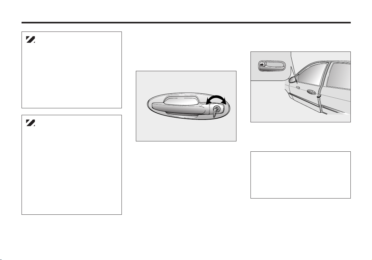
OPERATING DOOR LOCKS WITH KEY
LOCK UNLOCK
MMSA3001
• Both front doors can be locked and
unlocked with the key.
• Turn the key to the left to lock and to
the right to unlock the door.
• Once a door is unlocked, it may be
opened by pulling the door handle.
OPERATING DOOR LOCKSWITHOUT KEY
MMSA3002
To lock a door without the key, push the
inside door lock button to the “LOCK”
position and close the door.
✻ NOTICE
Always remove the ignition key,
engage the parking brake, close all
windows and lock all doors when
leaving your vehicle unattended.
3-9
Page 19
KNOWING YOUR VEHICLE
OPERATING DOOR LOCKS
FROM INSIDE THE VEHICLE
RED MARK
UNLOCK
• To lock a door, push the door lock
button to the “LOCK” position.
• To unlock a door, push the door lock
button to the “UNLOCK” position.
• To open a door, pull the door handle
towards the middle of your vehicle.
The door ajar warning light will
illuminate if a door is not fully closed.
Close the door completely and the light
will go out.
LOCK
MMSA3003
WARNING
Never leave children or animals
unattended in the vehicle. An
enclosed vehicle can become
extremely hot and depleted of
oxygen, causing death or
severe injury to children or to
animals who cannot escape the
vehicle.
CAUTION
The doors should always be fully
closed and locked while the vehicle
is in motion to prevent accidental
opening of the doors. Locked doors
will also discourage potential
intruders when the vehicle stops or
slows.
✻ NOTICE
When the door is locked, the red
mark on the switch is not visible.
POWER DOOR LOCKS
(IF EQUIPPED)
UNLOCK
The power door lock switch is located on
the driver’s armrest. If any door is open
when the switch is depressed, the door
will remain locked when closed.
✻ NOTICE
• Pushing the front portion of the
driver’s door lock switch will
cause all vehicle doors to lock.
• Pushing the rear portion of the
switch will cause all vehicle
doors to unlock.
LOCK
MMSA3004
3-10
Page 20
REAR DOOR CHILD
SAFETY LOCK
FREE
LOCK
MMSA3005
The child safety lock is provided to help
prevent children from accidentally
opening the rear doors from inside the
vehicle.
• To lock a rear door so that it cannot
be opened from the inside, push the
child safety lock located on the rear
edge of the door to the “LOCKED”
position before closing the door.
• To open a rear door while the child
safety lock is engaged, push the door
lock button to the “UNLOCK”
position (red mark is visible) then
pull the outside door handle.
WARNING - Rear Door
Locks
If children accidentally open the
rear doors while the vehicle is
in motion, they could fall out
and be seriously or fatally
injured. To prevent children
from opening the rear doors
from the inside, the rear door
safety locks should be used
whenever children are in the
vehicle.
WINDOWS
POWER WINDOWS
The ignition switch must be in the ON
position for power windows to operate.
Each door has a power window switch
that controls the door’s window.
However, the driver has a power window
lock switch which can cancel the
operation of the three passenger window
switches.
✻ NOTICE
To prevent the power window fuse
from malfunctioning and the power
window system from being
damaged, do not open or close
more than two windows at the
same time.
3-11
Page 21
KNOWING YOUR VEHICLE
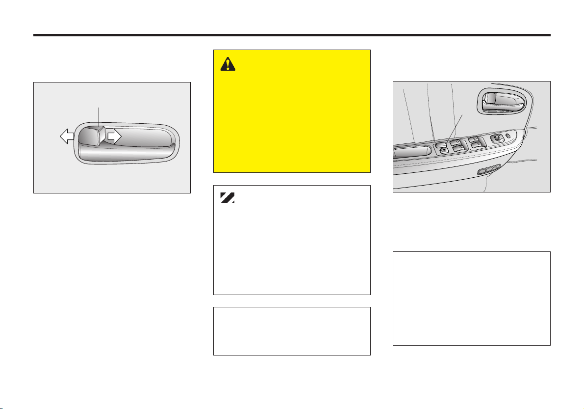
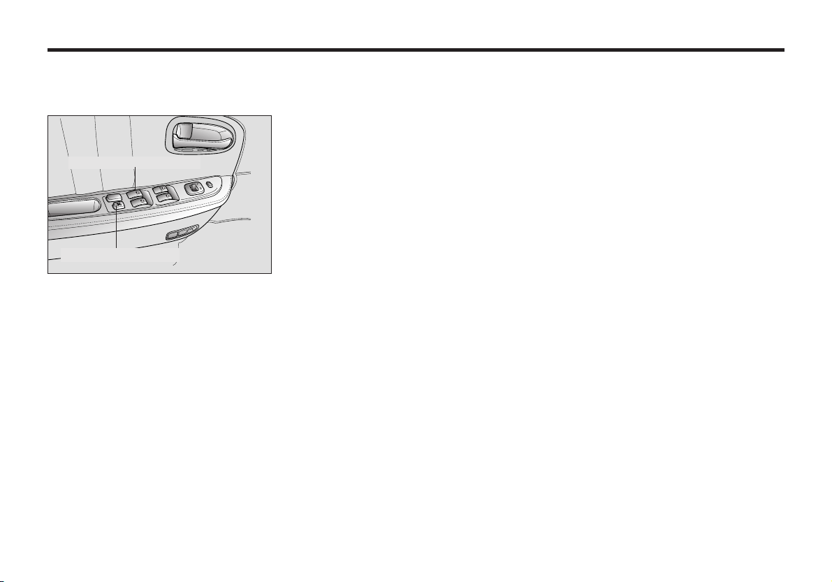
DRIVER’S DOOR POWER
WINDOW CONTROLS
Power window master control
Power window lock switch
All windows can be opened or closed
using the power window master control
on the driver’s door. To open a window,
press down on the corresponding power
window switch. To close a window, pull
up on the corresponding power window
switch.
MMSA3004
DRIVER’S WINDOW
AUTOMATIC-DOWN WINDOW
SWITCH
The driver’s window has an “AutomaticDown” feature. To activate the expressdown feature, momentarily depress the
front of the switch to the second detent
position. To cancel this feature, pull up
on the front of the switch and then
release it.
DRIVER’S POWER WINDOW
SWITCH
The driver’s power window switch
provides two (2) separate window-down
functions.
• Depressing the driver’s power
window switch completely, automatically lowers (Automatic-Down) the
driver’s window. To cancel this
function, pull up on the front of the
switch and release it.
• Depressing the driver’s power
window switch partially (to the first
detent) provides precise control of the
window-down position.
To raise/close the driver’s window,
pull up on the power window switch.
POWER WINDOW TIMER
(IF EQUIPPED)
The power windows can be operated for
approximately 30 seconds after the
ignition key is removed or turn to the
ACC or LOCK position. However, if the
front doors are opened, the power
windows cannot be operated even within
the 30 seconds after the ignition key
removal.
3-12
Page 22
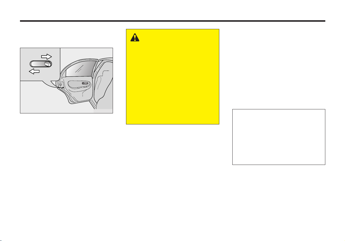
POWER WINDOW LOCK
SWITCH FEATURE
Power window lock switch
The driver can disable the power window
switches on all passenger doors by
depressing the power window lock switch
located on the driver’s door to ON. When
the power window lock switch is ON, the
driver’s master control can not operate the
passenger door power windows either.
MMSA3004
WARNING - Power
Windows
• Keep the power window lock
switch on the driver’s door in
the ON (depressed) position
except when someone is
operating a passenger door
window. Serious injury can
result from unintentional
window opera-tion, especially
to children.
• Always double check to make
sure all arms, hands, and other
obstructions are safely out of
the way before closing a
window.
✻ NOTICE
If you experience buffeting and
pulsation (wind shock) with either
side window open, you should open
the opposite window slightly to
reduce the condition.
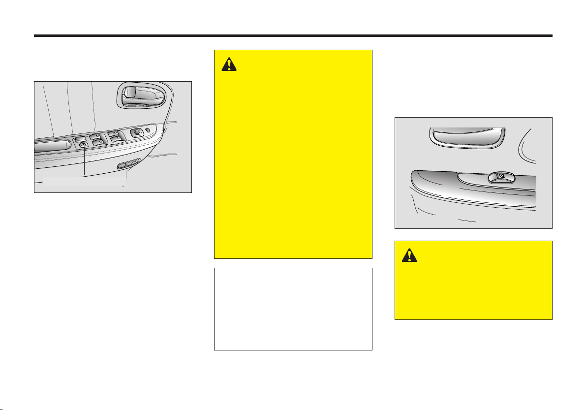
PASSENGER DOOR POWER
WINDOW CONTROLS
To open a window, press the front portion
of the switch down. To close a window,
pull the front portion of the switch up.
MMSA3006
WARNING - Passengers
Do not allow children to play
with the power windows. They
may seriously injure
themselves or others.
3-13
Page 23
KNOWING YOUR VEHICLE
SEATS
WARNING - Drivers
• Never adjust the driver’s seat
or seatback when the vehicle
is moving. Doing so could
cause loss of control, and
serious personal injury or
death.
• Do not allow packages or
other objects to interfere with
the normal position of a
seatback. These objects may
prevent the seatback from
locking, which could result in
serious injury or death in the
event of a sudden stop or
collision.
• Always drive and ride with
your seatback upright and
the lap portion of the safety
belt snug and low across the
hips.
• Children can be killed or
injured by the passenger air
bag. The back seat is the
safest place for children 12
and under. Make sure all
children use seat belts or
child seats.
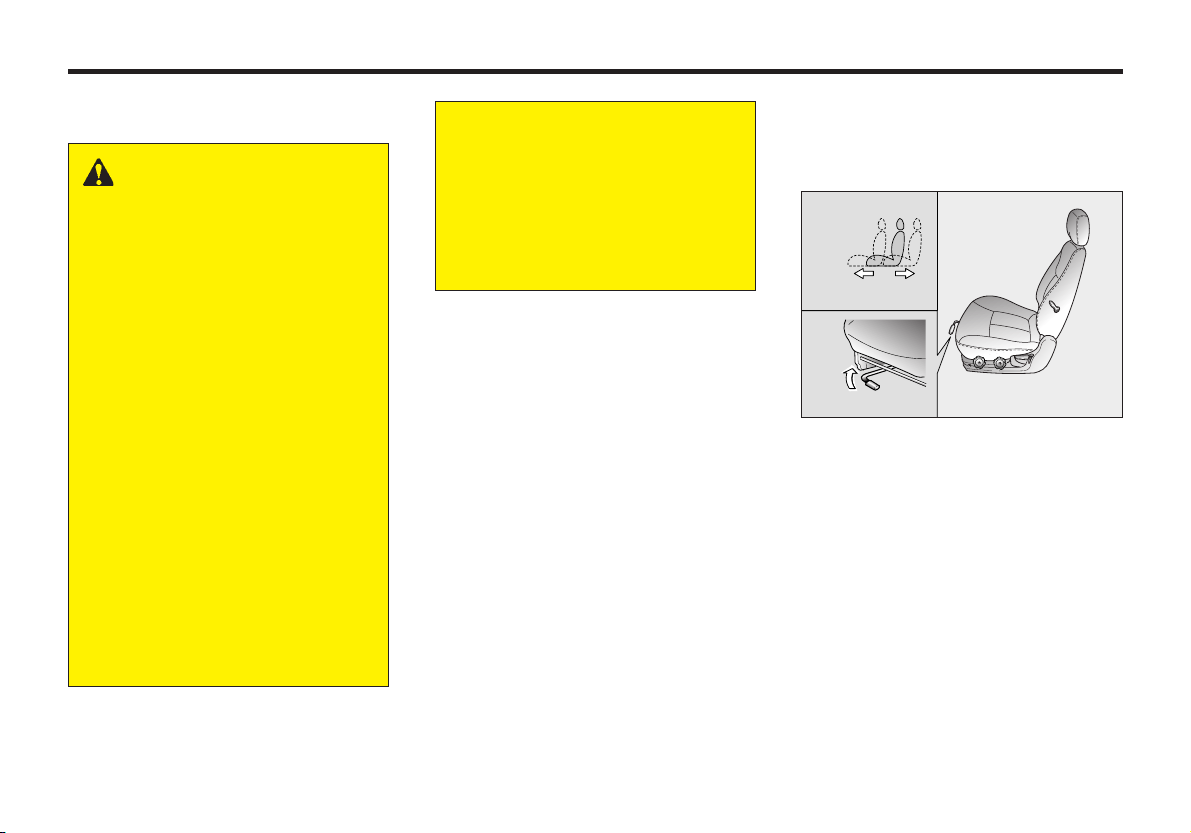
FRONT SEAT ADJUSTMENT
MOVING THE FRONT SEAT
FORWARD AND BACKWARD
MMSA3007
To move the seat forward or backward;
1. Pull the seat slide adjustment lever
under the front edge of the seat
cushion up and hold it.
2. Slide the seat to the position you
desire.
3. Release the lever and make sure the
seat is locked in place.
3-14
Page 24
CAUTION
Do not place anything under the
front seats. Loose objects might
interfere with the seat slide
mechanism or possibly roll out
from under the seat and interfere
with the operation of the brake,
clutch or accelerator foot pedals.
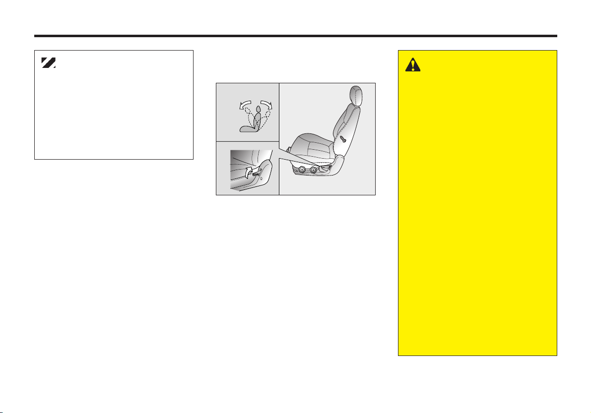
ADJUSTING THE FRONT
SEATBACK RECLINER
MMSA3008
To recline the seatback;
1. Lean forward slightly and lift up on
the seatback recline lever located on
the outside of the seat, toward the rear.
2. Lean back on the seat and adjust the
back of the seat to the position you
desire.
3. Release the lever and make sure the
seatback is locked in place. (The
lever MUST return to its orginal
position for the seatback to lock.)
WARNING - Passengers
To reduce the risk of sliding
under the lap portion of the
lap/shoulder belt, and potentially
suffering serious personal injury
or death in the event of a
collision, do not use the front
seatback in a reclined position
while the vehicle is in motion. If a
seat is reclined, the occupant’s
hip could slide under or out of
the lap portion of the
lap/shoulder belt during a
collision. If that occurs, the
occupant may no longer be
properly restrained, and the
safety belt could apply restraint
forces to the unprotected
abdomen resulting in serious
personal injury or death.
Therefore, keep the seatbacks in
a comfortably upright position
whenever the vehicle is in
motion.
3-15
Page 25
KNOWING YOUR VEHICLE
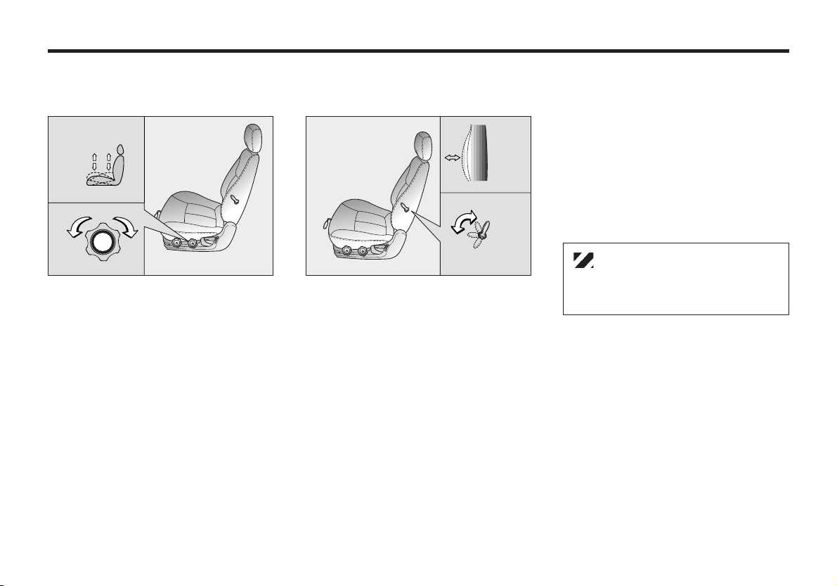
ADJUSTING THE HEIGHT OF
DRIVER’S SEAT CUSHION
MMSA3009
To change the height (front portion) of
the seat cushion, rotate the knob located
on the outside of the seat cushion.
• To lower the seat cushion, rotate the
knob toward the front of the vehicle.
• To raise the seat cushion, rotate the
knob toward the rear of the vehicle.
LUMBAR SUPPORT
MMSA3010
You can adjust the lumbar support by
moving the lever on the side of the
driver’s seatback. Pivoting the lever
toward the front of the vehicle increases
the lumbar support. Pivoting the lever
toward the rear of the vehicle decreases
the lumbar support.
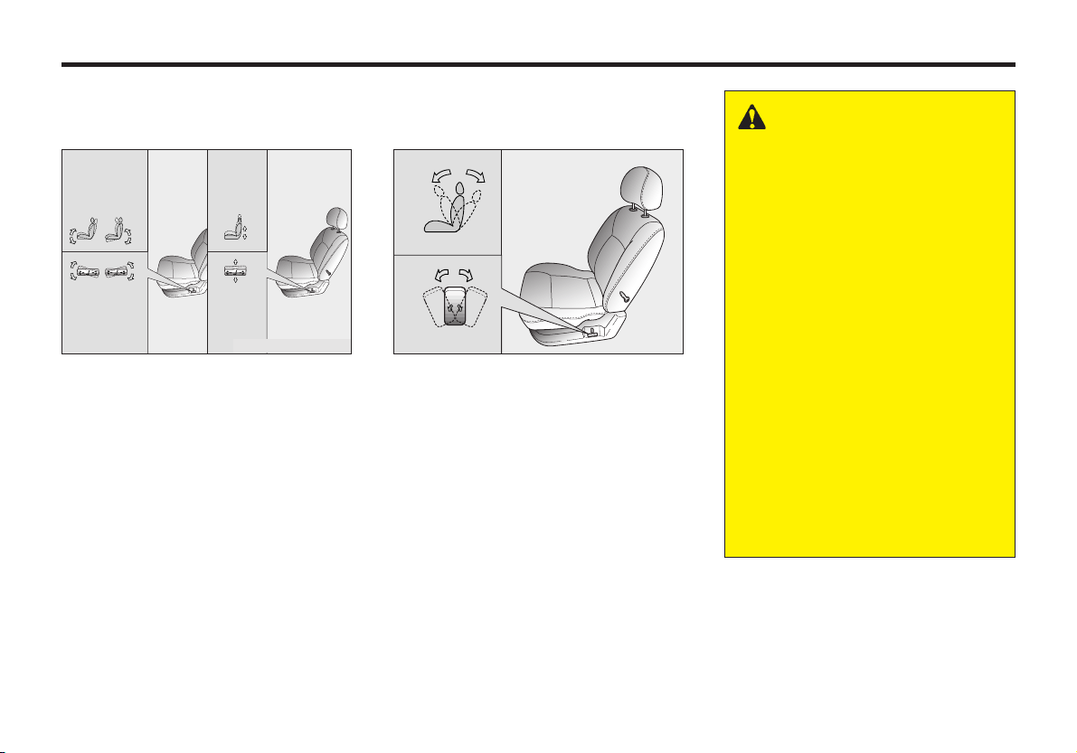
POWER DRIVER’S SEAT
(IF EQUIPPED)
The driver's seat can be adjusted
appropriately by using the control knob
on the left side of the seat. Before
driving, adjust the seat to the proper
position so as to easily control the
steering wheel, pedals and switches on
the instrument panel.
CAUTION
Do not operate two knobs at the
same time.
3-16
Page 26
WARNING
• Never attempt to adjust the
seat while the vehicle is
moving. This could result in
loss of control, and an
accident causing death,
serious injury, or property
damage.
• Do not sit or lean
unnecessarily close to the
airbag to get better
protection during its deployment in case of an accidents.
• Sit at least 10 inches (250
mm) away form the steering
wheel while driving the
vehicle to avoid injury during
air bag deployment in an
accident.
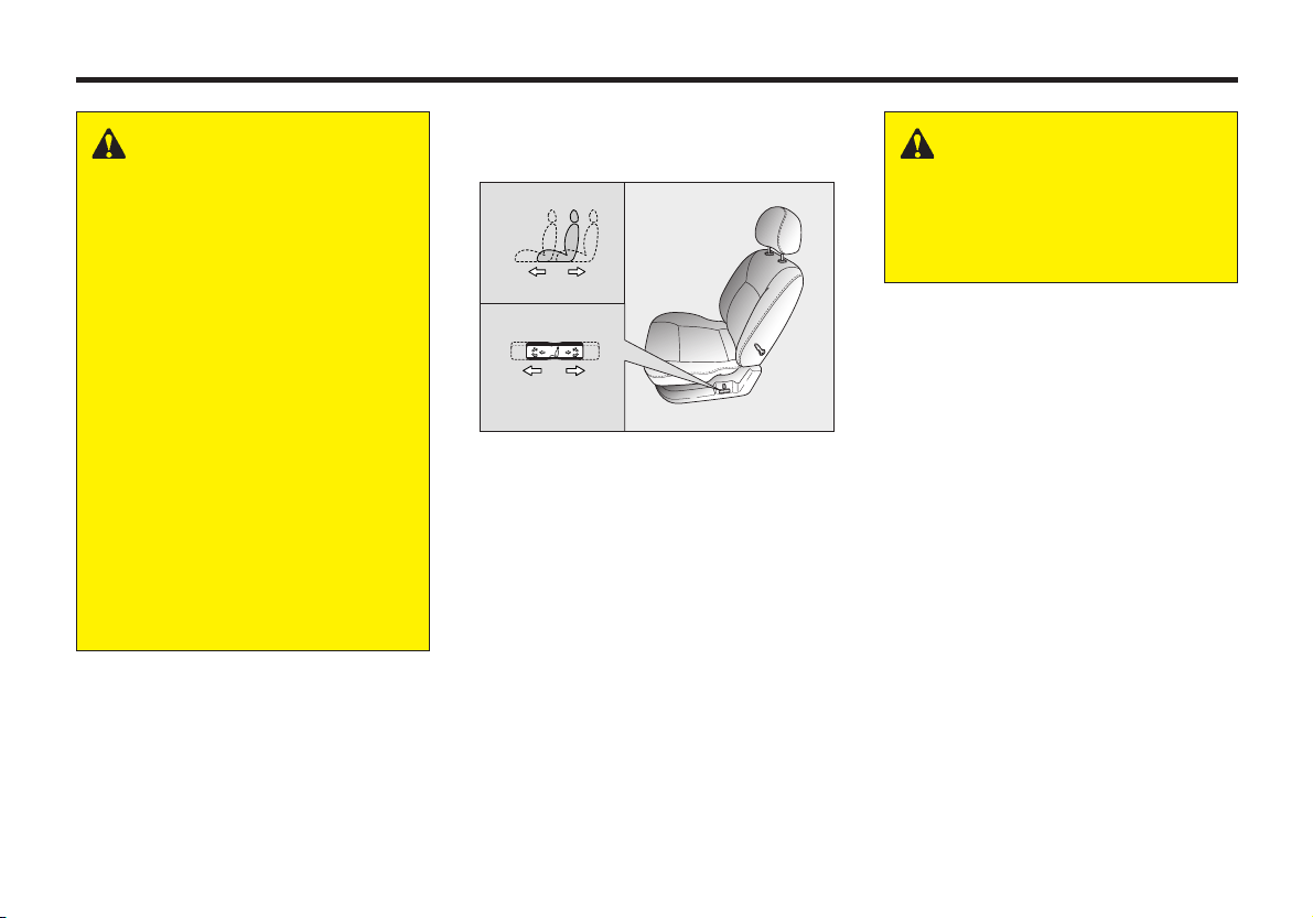
ADJUSTING SEAT FORWARD
AND BACKWARD
MMSA3011
Pull the control knob forward or
backward to move the seat forward or
backward to the desired position.
Release the knob and then the seat will
lock at that position.
1. Reclining Control Knob
2. Sliding and Height Adjusting Control
Knob
WARNING
To ensure the seat is locked
securely, attempt to move the
seat forward or backward
without using the control knob.
3-17
Page 27
KNOWING YOUR VEHICLE
SEAT CUSHION HEIGHT
ADJUSTMENT
MMSA3078/MMSA3015
Move the front portion of the control
knob up or down to raise or lower the
front part of the seat cushion. Move the
rear portion of the control knob up or
down to raise or lower the rear part of the
seat cushion.
ADJUSTING SEATBACK
ANGLE
MMSA3012
Rotate the upper portion of the control
knob forward or backward to recline the
seatback to the desired position. Release
the control knob and then the seatback
will lock in that position.
WARNING
To minimize the risk of personal
injury in the event of a collision
or a sudden stop, both the
driver's and passenger's
seatback should remain in an
upright position while the car is
in motion. The protection
provided by the seat belts and
airbags may be reduced significantly when the seatbacks are
reclined. There is a greater risk
that the seat occupants will
slide under the belt resulting in
serious injury if a crash occurs
when the seat-backs are
reclined. The seat belt cannot
provide full protection to an
occupant if the seat back is
reclined.
3-18
Page 28

HEATING THE FRONT
SEATS (IF EQUIPPED)
MMSA3079
The front seats are electrically heated
when the ignition switch is ON and the
corresponding heater switch, shown in
the illustration, is depressed. When
depressed, a thermostat regulates seat
temperature individually. To deactivate
the front seat heating system, depress the
corresponding heater switch again.
ADJUSTABLE HEADREST
(IF EQUIPPED)
Release lever
MMSA3016
To raise the headrest, simply pull it up to
the desired position. To lower the
headrest, press the release lever on the
left side grommet, while pushing the
headrest down to the desired position. To
remove the headrest, raise it as far as it
can go then press the release lever while
pulling upward.
The headrest may be adjusted forward to
three positions by pulling if forward. To
adjust the headrest backwards, pull it
forward and release it.(If equipped)
WARNING - Headrests
• To reduce the risk of head
and neck injuries, do not
operate the vehicle with the
headrest removed or
improperly posi-tioned.
• Do not attempt to adjust the
headrest while driving.
• Adjust the top of the headrest
so that it is even with the top
of your ears in order to
reduce the chance of injury in
the event of a collision.
3-19
Page 29
KNOWING YOUR VEHICLE
WARNING
To drive properly, adjust the
driver’s seat and its headrest
before starting. After doing so,
you should adjust the day/night
rearview mirror and the outside
rearview mirror.
SPLIT FOLDING REAR
SEAT
MMSA3014
The rear seatbacks fold forward to
provide additional cargo space and to
provide a access to the trunk area.
• To fold the rear seatback(s) down,
press the unlock button located in the
top of the seatbacks, then fold the
seatback forward and down.
• To raise the seatback, lift and push it
firmly until it clicks into place.
• When you return the seatback to its
upright position, reposition the rear
safety belts so that they can be used
by rear seat passengers.
WARNING - Cargo
Cargo should always be
secured to prevent it from
shifting and causing injury to
the vehicle occupants.
CAUTION
Do not remove the floor carpet in
your vehicle, emission controls
cause high exhaust temperatures
under the floor.
3-20
Page 30
✻ NOTICE
When returning the rear seatbacks
to the upright position, remember
to return the rear shoulder belts to
their proper position. Routing the
safety belt webbing through the
rear safety belt guides will help
keep the belts from being trapped
behind or under the seats.
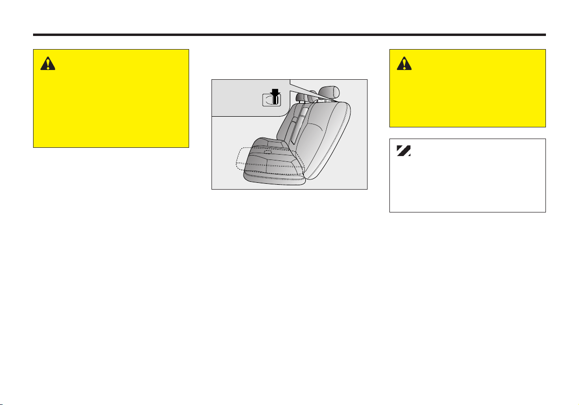
REAR SEATBACK LOCK
FREE LOCK
MMSA3018 MMSA3019
The rear seatback lock lever (located on
the backside of the rear seatback) is
always in the “LOCK” position when the
seatbacks are secured upright. To fold the
rear seatback down, the lock lever must be
moved to the “FREE” position. The lock
feature was designed to provide protection
from unauthorized entry into the trunk.
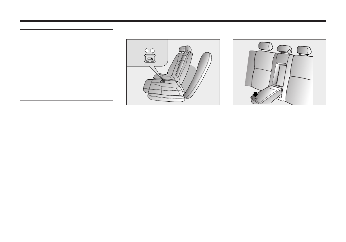
REAR SEAT ARMREST
This armrest is located in the center of
the rear seatback.
Open the armrest cover by pressing its
release button. A cup holder and stowage
compartment are inside the armrest.
3-21
Page 31

KNOWING YOUR VEHICLE
SAFETY BELTS
PRE-TENSIONER SEAT
BELT
2GHB3002
Your vehicle is equipped with driver’s
and front passenger’s pre-tensioner seat
belts. The purpose of the pre-tensioner is
to make sure that the seat belts fit tightly
against the occupant’s body in certain
frontal collisions.
The pre-tensioner seat belts can be
activated alone or, with the airbag, where
the frontal collision is severe enough.
Driver’s side airbag
1
Passenger’s
side airbag
2
3
MMSA3021
The pre-tensioner seat belt operates in
the same way as an Emergency Locking
Retractor (ELR) type of seat belt. When
the vehicle stops suddenly, or if the
occupant tries to lean forward too
quickly, the seat belt retractor will lock
into position. However, in certain frontal
collisions, the pretensioner will activate
and pull the seat belt into tighter contact
against the occupant’s body.
The seat belt pre-tensioner system
consists mainly of the following
components.
Their locations are shown in the
illustration.
1. SRS airbag warning light.
2. Seatbelt pre-tensioner assembly.
3. SRS control module.
WARNING
To obtain maximum benefit
from a pre-tensioner seat belt:
1. The seat belt must be worn
correctly.
2. The seat belt must be
adjusted to the correct
position.
3-22
Page 32

✻ NOTICE
• Both the driver’s and front
passenger’s pre-tensioner seat
belts will be activated in certain
frontal collisions. The pretensioner seat belts can be
activated alone or, where the
frontal collision is severe enough,
with the airbags. The pretensioners will be activated
under these conditions even if
the seat belts are not being worn
at the time of the collision.
• When the pre-tensioner seat
belts are activated, a loud noise
may be heard and fine dust,
which may appear to be smoke,
may be visible in the passenger
compartment. This dust is not
hazardous.
• Although it is harmless, the fine
dust may cause skin irritation
and should not be breathed for
prolonged periods. Wash your
hands and face thoroughly after
an accident in which the
pretensioner seat belts were
activated.
CAUTION
• Because the sensor that activates
the SRS airbag is connected with
pre-tensioner seat belt, the SRS
airbag warning light on the
instrument panel will blink for
approximately 6 seconds after
the ignition key has turned to the
“ON” or “ACC” positions. After
the six second period, the air bag
warning light will turn off.
• Please have the SRS airbag
system and the pre-tensioner
system inspected by an
Authorized Kia Dealer if the
following conditions occur:
1. The SRS warning light does
not illuminate when the
ignition switch is turned to
“ON” or “ACC”.
2. When the ignition switch is
turned to “ON” or “ACC” the
SRS warning light stays lit
after blinking for
approximately 6 second.
3. The SRS warning light illum-
inates while the vehicle is being
driven.
AIR
BAG
WARNING
• Pre-tensioners are designed
to operate only one time.
After activation, pretensioner
seat belts must be replaced.
All seat belts, of any type,
should always be replaced
after they have been worn
during a collision.
• The Pre-tensioner seat belt
assembly mechanisms
become hot during
activation. Do not touch the
pre-tensioner seat belt
assemblies for several
minutes after they have been
activated.
• Do not attempt to inspect or
replace the pre-tensioner
seat belts yourself. This
must be done by an
Authorized Kia Dealer.
• Do not strike the pretensioner seat belt
assemblies.
3-23
Page 33

• Do not attempt to service or
repair the pre-tensioner seat
belt system in any manner.
• Improper handling of the pretensioner seat belt
assemblies, and failure to
heed the warnings to not
strike, modify, inspect,
replace, service or repair the
pretensioner seat belt
assem-blies may lead to
improper operation or inadvertent activation and
serious injury.
Always wear the seat belts
when driving or riding in a
motor vehicle.
KNOWING YOUR VEHICLE
3-24
Page 34

SAFETY BELT RESTRAINT
SYSTEM
WARNING
The driver and all passengers
should always use the safety
belts provided in order to
minimize the risk of severe
bodily injury.
We strongly recommend that the driver
and all passengers be properly restrained
at all times by using the safety belts
provided with the vehicle. Proper use of
the safety belts decreases the risk of
severe injury or death in accidents or
sudden stops.
Safety belts provide the best restraint
when:
• The seatback is upright.
• The occupant is sitting upright (not
slouched).
• The lap belt portion of the safety belt
is snug and low on the hips.
• The shoulder belt portion of the
safety belt is snug against the chest.
• The knees are straight forward.
To help you remember to fasten your
safety belt, a warning light will flash and
a chime will sound.
See safety belt warning on page 4-22.
All seats have lap/shoulder belts.
The center rear seat has a lap/shoulder
belt.
Inertial locks in the safety belt retractors
allow all of the lap/shoulder safety belts
to remain unlocked during normal
vehicle operation.This allows the
occupants some freedom of movement
and increased comfort while using the
safety belts. If a force is applied to the
vehicle, such as a strong stop, a sharp
turn, or a collision, the safety belt
retractors will automatically lock the
safety belts.
Since the inertial locks do not require a
collision in order to lock up, you may
become aware of the safety belts locking
while braking or going around sharp
corners.
The center rear seat safety belt does not
have an inertial lock so it is always in a
locked condition.
Whenever possible, use the center rear
seat position to install your child
restraint. The center rear seat is the best
position to install your child restraint.
3-25
Page 35

KNOWING YOUR VEHICLE
WARNING - Twisted
Safety Belts
Never drive or ride with a twisted
or jammed safety belt. If you
cannot untwist or unjam the
safety belt, see your Kia Dealer
immediately.
WARNING - Safety Belt
Usage
Each seating position in your
vehicle has a specific safety belt
assembly which includes a
buckle and tongue that are
designed to be used together. 1)
Use the shoulder belt on the
outside shoulder only. Never
wear the shoulder belt under the
arm. 2) Never swing the safety
belt around your neck to fit over
the inside shoulder. 3) Never
use a single belt for more than
one person.
WARNING - Safety Belt
Care
Safety belts should be
inspected periodically for
excessive wear or damage. Pull
out each belt fully and look for
excessive fraying, cuts, burns
or other damage. Make sure that
the lap/shoulder belts return
smoothly and easily into the
retractor. Check the latches to
make sure they latch and
release without interference or
delay. Any belt not in good
condition or in good working
order should be promptly
replaced.
CAUTION - Damage to
Safety Belts
Never close the doors on any part
of the lap or shoulder belt. It can
damage the safety belt or buckle
which could increase the risk of
injury in case of an accident.
3-26
Page 36

RESTRAINT OF PREGNANT
WOMEN
Pregnant women should wear lap/shoulder
belt assemblies whenever possible
according to specific recommendations by
their doctors. The lap portion of the belt
should be worn AS SNUGLY AND
LOW AS POSSIBLE.
WARNING - Pregnant
Women
Pregnant women must never
place the lap portion of the
safety belt over the area of the
abdomen where the fetus is
located or above the abdomen.
RESTRAINT OF INFANTS
AND SMALL CHILDREN
Small children and infants should be
restrained by an approved child-restraint
system to help protect them while riding
in a vehicle.
Never allow a child to stand or kneel on
the seat of a moving vehicle. Never
allow a safety belt to be placed around
both a child and an adult or around two
children at the same time.
Children can be killed or injured by the
passenger air bag. The back seat is the
safest place for children 12 and under.
WARNING - Children on
Laps
Never hold a child on your lap
or in your arms in a moving
vehicle.
Even a very strong person
cannot hold onto a child in the
event of even a minor collision.
Many companies manufacture child
restraint systems (often called child
seats) for infants and small children. An
acceptable child restraint system must
always satisfy the Safety Standards of
your country. Make sure that any childrestraint system you use in your vehicle
is labeled as complying with those safety
standards.
The child-restraint system should be
chosen to fit both the size of the child
and the size of the vehicle seat. Be sure
to follow any instructions provided by
the child-restraint system manufacturer
when installing the child-restraint
system.
3-27
Page 37

KNOWING YOUR VEHICLE
CAUTION - Hot Metal
Parts
Safety belts and seats can become
hot in a vehicle that has been closed
during warm/hot weather; they
could burn a child. Check seat
covers and buckles before you
place a child anywhere near them.
RESTRAINT OF LARGE
CHILDREN
As children grow, they may need to use
new child-restraint systems, including
larger child seats or booster seats, which
are appropriate for their increased size.
A child who has outgrown available
child-restraint systems should use the
belts provided in the vehicle. When seated
in the rear outboard seats, the child should
be restrained by the lap/shoulder belt.
If the shoulder belt portion slightly
touches the child’s neck or face, try
placing the child closer to the center of the
vehicle. If the shoulder belt still touches
their face or neck they may need to be
3-28
returned to a child restraint system.
In addition, after-market devices are
available from independent manufacturers
which help pull the shoulder belt down
and away from the child’s face or neck.
WARNING - Shoulder
Belts ON Small Children
• Never allow a shoulder belt to
be in contact with a child’s
neck or face while the vehicle
is in motion.
• If safety belts are not properly
worn and adjusted, the risk of
death or serious injury to
such a child is high.
WARNING - Child
Restraints
• All child restraint systems are
designed to be secured in
vehicle seats by lap belts or
the lap-belt portion of a lap/
should-er belt.
Children will be endangered
in a crash if their child
restraint systems are not
properly secur-ed by the
safety belts in the vehicle.
• According to accident
statistics, children are safer
when proper-ly restrained in
the rear seatin positions
rather than the front seating
positions.
• When a child restraint system
is not secured by a safety
belt, store it in the trunk so
that it will not be thrown
forward in the event of a
sudden stop or accident.
Page 38

PLACEMENT OF A CHILD
RESTRAINT SYSTEM
We recommend that, whenever possible,
you put the child restraint in the center
position of the rear seat.
If the center rear seat is not available, or
you are using more than one child
restraint system in the vehicle at the
same time, the rear safety belts have
been designed to allow a child restraint
to be used in these positions. Since those
safety belts normally lock only under
extreme or emergency conditions
(emergency lock mode) you must
manually adjust those belts to the auto
lock mode.
WARNING
When a child restraint is not in
use, make sure that it is
secured by a safety belt. In a
sudden stop or accident, a
loose child restraint could be
thrown forward and injure
someone.
✻ NOTICE
The driver’s safety belt
incorporates the emergency lock
mode only.
WARNING - Restraint
Instructions
Failure to observe this manuals
instructions regarding child
restraint systems and the
instructions provided with the
child restraint system could
increase the chance and/or
severity of injury in an accident.
3-29
Page 39

MMSA3080
KNOWING YOUR VEHICLE
MMSA3027
To secure a child restraint in the rear
outboard seats, follow the procedure
below.
1. Place the child restraint system in the
seat and route the lap/shoulder belt
around or through the restraint,
following the restraint manufacturer’s
instructions. Be sure the safety belt
webbing is not twisted.
WARNING - Child
Restraint Placement
Never use a child restraint in
the front passenger seat. In a
collision the air bag inflates
with great force. A child in a
restraint in the front passenger
seat can be severely or fatally
injured by the power of the air
bag.
3-30
Placing a Passenger Safety Belt
Into the Auto Lock Mode
The use of the auto lock mode will
ensure that the normal movement of the
child in the vehicle does not cause the
safety belt to be pulled out and loosen
the firmness of its hold on the child
restraint system.
Page 40

"Click"
2. Fasten the lap/shoulder belt latch into
the buckle. Listen for the distinct
“click” sound.
Position the release button so that it is
easy to access in case of an emergency.
MMSA3028MMSA3027
3. Pull the shoulder portion of the safety
belt all the way out. When the
shoulder portion of the safety belt is
fully extended, it will shift the
retractor to the “Auto Lock” (child
restraint) mode.
MMSA3029
4. Slowly allow the belt to retract. Pull
up on the shoulder webbing. A
“clicking” or “ratcheting” sound will
be heard as the belt retracts. This
indicates the retractor is now in the
automatic locking mode. Push down
on the child restraint while you pull up
on the belt in order to remove any
slack in the belt.
3-31
Page 41

KNOWING YOUR VEHICLE
MMSA3030
5. Before placing the child in the child
restraint, forcibly try to push the seat
from side to side and forward to make
sure that the seat is securely held in
place.
6. Double check that the retractor is in
the automatic locking mode by trying
to pull the shoulder portion of the
safety belt out of the retractor. If you
cannot pull the belt out of the retractor,
it is in the automatic locking mode. If
you can, repeat step 4.
To remove the child restraint, press the
release button on the buckle and then
pull the lap/shoulder belt out of the
restraint and allow the safety belt to
retract fully.
WARNING - Auto Lock
Mode
The lap/shoulder belt
automatically returns to the
“emergency lock mode”
whenever the belt is allowed to
retract fully. Therefore, the
preceding seven steps must be
followed each time a child
restraint is installed.
If the safety belt is not placed in
the “auto lock” mode, severe
injury or death could occur to
the child and/or other
occupants in the vehicle in a
collision, since the child
restraint will not be effectively
held in place.
✻ NOTICE
When the safety belt is allowed to
retract to its fully stowed position,
the retractor will automatically
switch from the “Auto Lock”
mode to the emergency lock mode
for normal adult usage.
3-32
Page 42

INSTALLING A CHILD
RESTRAINT IN THE REAR
CENTER SEAT
MMSA3031
To install a child restraint in the rear
center seat, do the following:
1. Place the child-restraint in the desired
position. Route the lap/ shoulder belt
through the restraint according to the
seat manufacturer’s instructions.
2. Insert the tongue plate into the
buckle.
3. Adjust the lap/ shoulder safety belt
for a snug hold on the child restraint
by pulling on the loose end of the
belt.
Child seat anchorage position
For small children and babies, the use of
a child seat or infant seat is strongly
recommended. This child seat or infant
seat should be of appropriate size for the
child and should be installed in
accordance with the manufacturer’s
instructions. It is further recommended
that the seat be placed in the vehicle’s
rear seat since this can make an
important contribution to safety. Your
vehicle is provided with three child
restraint hook holders on the package
tray behind the rear seat for installing the
child seat or infant seat.
WARNING - Child
Restraint Placement
Never use a child restraint in the
front passenger seat. A child in
a child restraint installed in the
front passenger seat can be
severely or fatally injured by an
air bag which could impact the
child restraint with great force
when the air bag inflates.
3-33
Page 43

KNOWING YOUR VEHICLE
CHILD RESTRAINT
ANCHORAGE POSITION
Child Restraint Anchorage
Your vehicle is equipped with an anchor
for securing the tether strap of a child
restraint system (child seat).
The child restraint anchor fittings are
installed on the shelf behind the rear seat.
WARNING
If the tether strap is clipped
incorrectly, the child restraint
seat may not be restrained
properly in the event of a
collision.
MMSA3032
Installing a child restraint seat ;
1. Position the child restraint seat on the
rear passenger seat cushion.
2. Route the child restraint seat tether
strap over the back of the seat.
For vehicles with adjustable head
restraints, route the tether strap under
the head restraint and between the
head restraint posts, otherwise route
the tether strap over the top of the
seatback.
3. Locate the correct anchor on the
package tray behind the rear seat for
the selected seating position.
4. Open the tether anchor cover.
5. Clip the tether strap hook to the
tether strap hook holder.
6. Tighten the tether strap to secure the
seat.
WARNING - Child
Restraint
Check that the child restraint
system is secure by pushing and
pulling it in different directions.
Incorrectly fitted child restraints
may swing, twist, tip or come
away causing death or injury.
WARNING - Child
Restraint Anchorage
• Child restraint anchorages are
designed to withstand only
those loads imposed by
correctly fitted child restraints.
Under no circumstances are
they to be used for adult seat
belts or harnesses or for
attaching other items or
equipment to the vehicle.
• The tether strap may not work
properly if attached
somewhere other than the
correct tether anchor.
3-34
Page 44

CHILD SEAT LOWER
ANCHORS
Child lower anchor
indicater
MMSA3082
Some child seat manufacturers make
child restraint seats that are labeled as
ISOFIX or ISOFIX-compatible child
restraint seats. These seats include two
rigid or webbing mounted attachments
that connect to two ISOFIX anchors at
specific seating positions in your vehicle.
This type of child restraint seat
eliminates the need to use seat belts to
attach the child seat for forward-facing
child restraint seats.
Zipper
Child lower anchor
MMSB3035
There is a symbol located on the lower
portion of each side of the rear seatbacks.
These symbols indicate the position of
the lower anchors for child restraints so
equipped. A zipper is located directly
beneath each indicator, which when
opened will expose the metal anchor.
MMSA3036
ISOFIX anchors have been provided in
your vehicle. The ISOFIX anchors are
located in the left and right outboard rear
seating positions. Their locations are
shown in the illustration. There is no
ISOFIX anchor provided for the center
rear seating position.
The ISOFIX anchors are located
between the seatback and the seat
cushion of the rear seat left and right
outboard seating positions.
Follow the child seat manufacturer’s
instructions to properly install child
restraint seats with ISOFIX or ISOFIXcompatible attachments.
3-35
Page 45

KNOWING YOUR VEHICLE
Once you have installed the ISOFIX
child restraint, assure that the seat is
properly attached to the ISOFIX and
tether anchors. Also, test the child
restraint seat before you place the child
in it. Tilt the seat from side to side. Also
try to tug the seat forward. Check to see
if the anchors hold the seat in place.
WARNING
• If the child restraint is not
anchored properly, the risk of
a child being seriously injured
or killed in a collision greatly
increases.
• Do not mount more than one
child restraint to a single
tether or to a child restraint
lower anchorage point. The
improper increased load may
cause the anchorage points or
tether anchor to break,
causing serious injury or
death.
• Do not install a child restraint
seat at the rear center seating
position using the vehicle’s
ISOFIX anchors. The ISOFIX
anchors are only provided for
the left and right outboard rear
seating positions. Do not
misuse the ISOFIX anchors by
attempting to attach a child
restraint seat in the middle rear
seating position position to the
ISOFIX anchors. In a crash, the
child restraint seat ISOFIX
attachments may not be strong
enough to secure the child
restraint seat improperly in the
rear center seating position
and may break, causing
serious injury or death.
Attach the ISOFIX or ISOFIX-
•
compatible child restraint seat
only to the appropriate locations
shown in the illustration.
• Always follow the installation
and use instructions provided
by the manufacturer of the
child restraint.
SAFETY BELT WARNING
LIGHT AND CHIME
As a reminder to the driver and
passenger, safety belt warning light will
blink for approximately 6 seconds each
time you turn the ignition switch ON.
If the driver's lap/shoulder belt is not
fastened when the key is turned ON or if
it is unfastened after the key is turned
ON, the safety belt warning light blinks
for approximately 6 seconds and safety
belt warning chime sounds for
approximately 6 seconds.
Safety belt warning light
AN7B03016
3-36
Page 46

FRONT LAP/SHOULDER
BELT
TO FASTEN THE FRONT
LAP/SHOULDER BELT:
1. Grasp the buckle and tongue plate.
2. Slowly pull the lap/shoulder belt out
from the retractor.
MMSA3023
3. Insert the tongue plate into the open
end of the buckle until an audible
“Click” is heard, indicating the belt is
locked in the buckle.
MMSA3024
4. Position the lap portion of the belt
across your lap as LOW ON THE
HIPS as possible to reduce the risk of
sliding under it during an accident.
Adjust the belt to a SNUG FIT by
pulling up on the shoulder portion of
the safety belt. The belt retractor
applies tension to the belt in order to
take up excess webbing automatically
and to maintain tension on the belt.
For maximum safety, do not put any
excess slack into the safety belt.
3-37
Page 47

KNOWING YOUR VEHICLE
Adjustable
shoulder anchor
(if equipped)
MMSA3025
5. You can adjust the height of the
shoulder anchor to one of the four
positions. Adjust the shoulder anchor
position to your size.
To raise the anchor position, push the
knob and push the anchor up. To
lower the anchor position, push the
knob and slide the anchor down.
After adjustment, make sure the
anchor is locked in position.
WARNING - Front Safety
Belts
• The front seatbacks should
always remain in a
comfortable, upright position
while the vehicle is in motion.
The safety belt system will
provide the most protection
with the seatbacks in an
upright position.
Never wear the shoulder
portion of the safety belt
under the outside arm or
behind the back.
• Never wear the shoulder
portion of the safety belt
across the neck or face.
• Wear the lap portion of the
safety belt as low on the hips
as possible. Be sure the lap
belt fits snugly around the
hips. Never wear the lap belt
over your waist.
• Never drive or ride with a
twisted or jammed safety belt.
If you cannot untwist or
unjam the safety belt, see the
nearest Kia Dealer
immediately.
• Never use a single belt to
restrain more than one
person at a time.
Failure to follow these warnings
will increase the risk and
severity of injury in an accident.
3-38
Page 48

TO UNFASTEN THE FRONT
LAP/SHOULDER BELT:
Press the release button on the buckle.
3 POINT REAR CENTER
BELT (IF EQUIPPED)
TO FASTEN THE REAR
CENTER BELT
(A)
(B)
(B)
MMSA3026
(A)
(C)
(D)
(C)
MMSA3071
1. Slowly pull the tongue plates out
from the retractor.
2. Insert the tongue plate (A) into the
open end of the buckle (C) until an
audible “click" is heard, indicating
the latch is locked. Make sure the
belt is not twisted.
(D)
MMSA3072
3. Pull the tongue plate (B) and insert
the tongue plate into the open end of
the buckle (D) until an audible
“click” is heard, indicating the latch
is locked. Make sure the belt is not
twisted.
3-39
Page 49

KNOWING YOUR VEHICLE
There will be an audible “click” when
the tab locks in the buckle. The seat belt
automatically adjusts to the proper length
only after the lap belt is adjusted
manually so that it fits snugly around
your hips, if you lean forward in a slow,
easy motion, the belt will extend and let
you move around. If there is a sudden
stop or impact, the belt will lock into
position. It will also lock if you try to
lean forward too quickly.
3-40
WARNING
When using the rear seat
center belt, you must lock all
tongue plates and buckles. If
any tongue plate or buckle is
not locked, it will increase the
chance of injury in the event of
collision.
TO UNFASTEN THE REAR
CENTER BELT
(B)
(D)
(A)
(B)
(A)
(C)
1. Press the release button on the buckle
(D) and remove the tongue plate (B)
from the buckle (D).
2. Press the release button on the buckle
(C) and remove the tongue plate (A)
from the buckle (C).
The belt webbing will retract
automatically.
(D)
(C)
MMSA3081
Page 50

PROPER USE AND CARE
OF THE SAFETY BELT
SYSTEM
To ensure that the safety belts provide
the maximum protection, please follow
these instructions:
• Use the belts at all times - even on
short trips.
• If the safety belt is twisted, straighten
it prior to use.
• Keep sharp edges and damaging
objects away from the belts.
• Periodically inspect belt webbing,
anchors, buckles, and all other parts
for signs of wear and damage.
Replace damaged, excessively worn
or questionable parts immediately.
• To clean the belt webbing, use any
mild soap solution recommended for
cleaning upholstery or carpets.
Follow the instructions provided with
the soap.
Do not bleach or dye the webbing
because this may weaken the
webbing fibers and allow them to fail
when loaded in a collision.
• Do not make modifications or
additions to the safety belt.
• After wearing a safety belt, make
sure it fully retracts to the stowed
position. Do not allow the belt to get
caught in the door when you close it.
3-41
Page 51

KNOWING YOUR VEHICLE
AIR BAG SUPPLEMENTAL
RESTRAINT SYSTEM
WHAT YOUR AIR BAG
SYSTEM DOES
Your vehicle is equipped with a dual
Supplemental Restraint System (SRS),
which includes an air bag for the driver
and another air bag for the front
passenger.
WHAT YOUR AIR BAG
SYSTEM DOES NOT DO
The air bag system is designed to
supplement or add to the protection
provided to properly BELTED
occupants in moderate to severe frontal
collisions. It is not a substitute for the
driver’s or front passenger’s safety belt
and it does not provide restraint to the
lower body.
WHY DIDN’T MY AIR BAG
GO OFF IN A COLLISION?
There are many types of accidents in
which the air bag would not be expected
to provide additional protection. These
include side or rear impacts, rollovers,
and second or third impacts in multipleimpact accidents as well as low speed
impacts. Remember: air bags are only
designed to inflate when the impact
would throw the occupant into the air
bags -generally from a little to the left to
a little to the right of straight ahead. In
other words, just because your vehicle is
damaged end even if it is totally
unusable, don’t be surprised that the
airbag(s) did not inflate.
3-42
Page 52

THE IMPORTANCE OF
USING SAFETY BELTS
There are four very important reasons to
use safety belts even with an air bag
system, they:
• Help keep you in the proper position
(away from the air bag) when it
inflates.
• Reduce the risk of harm in rollover,
side or rear impact collisions,
because an air bag is not designed to
inflate in such situations.
• Reduce the risk of harm in frontal
collisions that are not severe enough
to activate the supplemental restraint
system.
• Reduce the risk of being thrown from
your vehicle.
WARNING - Air Bags &
Safety Belts
• Even in vehicles with air bags,
you and your passengers
must always wear the safety
belts provided in order to
minimize the risk and severity
of injury in the event of a
collision or rollover.
• Always wear your safety belt.
It can help keep you away
from the air bags during
heavy braking just before a
collision.
• Air bags are designed to
inflate only in severe frontal
collisions and will generally
not provide protection in side
or rear impacts, rollovers or
less severe frontal collisions.
They will also not provide
protection from later impacts
in a multi-impact collision.
• If your vehicle has been
subjected to flood conditions
(e.g. soaked carpeting/
standing water on the floor of
the vehicle, etc.) or if your
vehicle has become flood
damaged in any way, do not
attempt to start the vehicle or
put the key in the ignition
before disconnecting the
battery. This may cause air
bag deployment, which could
result in serious personal
injury or death. Have the
vehicle towed to an
Authorized Kia Dealer for
inspection and necessary
repairs.
3-43
Page 53

KNOWING YOUR VEHICLE
AIR BAG SYSTEM
COMPONENTS
The main components of your vehicle’s
SRS are:
• One air bag in the steering wheel for
the driver, and another in the
dashboard for the front passenger.
• A diagnostic system that continually
monitors system operation.
• An indicator light to warn you of a
possible problem with the system.
• Emergency power backup in case
your car’s electrical system is
disconnected in a crash.
R
E
S
A
C
C
E
L
C
A
N
C
E
L
C
O
A
S
T
S
E
T
MMSA3037A
To indicate that your vehicle is equipped
with air bags, the air bag covers on the
steering wheel and on the dashboard are
marked with “SRS AIR BAG.”
HOW THE AIR BAG SYSTEM
WORKS
The driver’s air bag is stored in the
center of the steering wheel. The
passenger side air bag is stored in the
front instrument panel above the glove
box.
If you ever have a severe frontal
collision, your air bags will instantly
inflate to help protect you from serious
physical injury.
There is no single vehicle speed at which
the air bags will inflate. Generally, air
bags are designed to inflate in severe
frontal collisions. The air bag
Supplemental Restraint System (SRS)
reacts to the severity of a collision and its
direction. These two factors determine
whether the sensors send out an
electronic deployment or inflation signal.
Whether the air bags will inflate depends
on a number of factors including vehicle
speed, angle of impact and the density
and stiffness of the vehicles or objects
that your vehicle hits in the collision.
3-44
Page 54

The air bags will completely inflate
and deflate in less than 1/10 of one
second.
The speed of inflation and deflation
protects the driver’s ability to operate the
vehicle. This is important in crashes
where a vehicle continues to move after
an impact and the driver still has some
control of the vehicle’s steering, braking,
throttle and/or transmission systems.
It is virtually impossible for you to see
the air bags inflate during an accident.
It is much more likely that you will
simply see the deflated air bags hanging
out of their storage compartments after
the collision.
In order to help provide protection in a
severe collision, the air bags must inflate
repidly. However, that speed also causes
the air bags to expand with a great deal of
force. The speed of this inflation has been
determined by the Canadian Motor
Vehicle Safety Standards (CMVSS) to
reduce the likelihood of serious or lifethreatening injuries and is thus a
mandatory part of air bag design.
Steering wheel air bag
AS2B03033
Thus, air bag inflation could also cause
injuries which normally can include facial
abrasions, bruises and broken bones.
However, there are even
circumstances under which contact
with the steering wheel air bag can
cause fatal injuries, especially if the
occupant is positioned excessively
close to the steering wheel.
YOU MUST ALWAYS SIT AS FAR
BACK FROM THE STEERING
WHEEL AIR BAG AS POSSIBLE,
WHILE STILL MAINTAINING A
COMFORTABLE SEATING POSITION
FOR GOOD VEHICLE CONTROL, IN
ORDER TO REDUCE THE RISK OF
WARNING - Air Bag
Injuries
• Sit as far back from the
steering wheel as possible
without interfering with your
control of the vehicle.
Positioning yourself too close
to the steering wheel can
result in serious or even fatal
injuries if the air bag deploys.
• Never place objects over the
air bag storage compartments
or between the air bags and
yourself. Due to the speed and
force of the air bag inflation,
such objects could hit your
body at high speed and cause
severe bodily injury and even
death.
INJURY OR DEATH IN A COLLISION.
3-45
Page 55

NOISE AND SMOKE
When the air bags inflate, they make a
loud noise and they leave smoke and
powder in the air inside of the vehicle.
This is normal and is a result of the
ignition of the air bag inflator.
After the air bags inflate, you may feel
substantial discomfort in breathing due
both to the contact by your chest with
both the safety belt and the air bag, as
well as from breathing the smoke and
powder.
We strongly urge you to open your
doors and/or windows as promptly as
possible after impact in order to
reduce discomfort and prevent
prolonged exposure to the smoke and
powder.
KNOWING YOUR VEHICLE
WARNING - Hot Metal
Parts
When the air bags deploy, the
air bag inflators in the steering
wheel and/or in the dashboard
are very hot. To prevent injury,
do not touch the air bag storage
area’s internal components
immediately after an air bag has
inflated.
3-46
Page 56

THE IMPORTANCE OF THE
PASSENGER BEING
PROPERLY SEATED
S
R
S
AIRBAG
G
IN
N
R
A
W
MMSA3038
The reason for this is that in most frontal
impacts there is substantial pre-impact
braking which tends to throw the
occupants forward. If the right front
passenger is not using their safety belt,
they will be directly in front of or even
touching the air bag storage
compartment when inflation occurs. In
that situation, death or severe injury is
possible.
WARNING - Right Front
Seat
Pre-impact braking could throw
an unbelted passenger toward
or onto the air bag storage
compartment. Upon impact in a
collision, the air bag would
rapidly inflate and possibly
severely injure or kill that
occupant who failed to wear
their safety belt.
The front seat passenger’s air bag is
much larger than the driver’s air bag and
inflates with considerably more force. It
can seriously hurt or kill a passenger
who is not in the proper position and
wearing the safety belt properly. The
front passenger should always move
their seat as far back as practical and sit
well back in the seat. It is essential that
the front passenger always wear their
safety belt, even when mounting in a
parking lot or up a drive way into a
garage.
Because of the air bag, you must NEVER
INSTALL A CHILD RESTRAINT
SYSTEM IN THE FRONT PASSENGER
SEAT.
There is a very significant risk of serious
or fatal injuries to a child in a child
restraint if the right front passenger air
bag inflates. We also strongly recommend
that you do not put a front-facing child
restraint system in the front passenger
seat.
3-47
Page 57

WARNING - Front
Passengers
• NEVER use a child restraint
in the front seat. In the front
seat, a child restraint would
be positioned too close to
where the air bags are stored
and in the event an air bag
deploys, the air bag would
impact the child restraint and
cause serious injuries or
death.
• Failure to observe the
instructions provided with
the child restraint system
could increase the risk
and/or severity of injury in an
accident.
KNOWING YOUR VEHICLE
PASSENGER PRESENCE
DETECTION
The passenger presence detection system
detects the presence of a passenger in the
front seat. If no passenger is recognized
on the front passenger seat, the
deployment of the front passenger and/or
side airbag will be prevented. This
system is designed to prevent the
replacement of airbag components that
deploy needlessly in an accident.
WARNING
The passenger presence
detection system is NOT
intended to prevent airbag
deployment while a child is in
the front passenger’s seat. it is
intended ONLY as a means to
reduce unnecessary collision
damage repair expense by
preventing airbag and seat belt
pretensioner deployment when
the right front passenger seat is
unoccupied. Deployment is still
possible if only a few pounds
are placed upon the seat.
Therefore, children must not be
transported in the front seat. All
children must be seated in the
rear seat and properly
restrained with the vehicle’s
restraint system or a child
restraint system appropriate for
the child’s size and weight.
3-48
Page 58

SIDE AIRBAG (IF EQUIPPED)
MMSA3040
Your vehicle is equipped with a side
airbag in each front seat. The purpose of
the airbag is to provide the vehicle’s
driver and/or the front passenger with
additional protection other than that
offered by the seatbelt alone. The side
impact airbags are designed to deploy
only during certain side-impact collisions,
depending on the crash severity, angle,
speed and point of impact. The air bags
are not designed to deploy in all side
impact situations.
Side airbag
sensor
MMSA3041
WARNING
• For best protection from the
side airbag system and to
avoid being injuried by the
deploying side airbag, both
front seat occupants should
sit in an upright position with
the seat belt properly
fastened. The driver’s hands
should be placed on the
steering wheel at the 9:00
and 3:00 o’clock positions.
The passenger’s arms and
hands should be placed in
their laps.
• Do not use any accessory seat
covers.
• Use of seat covers could
reduce the effectiveness of
the system.
• Do not install any
accessories on the side or
near the side airbag.
3-49
Page 59

KNOWING YOUR VEHICLE
• Do not use excessive force
on the side of the seat.
• Do not place any objects
over the airbag or between
the airbag and yourself.
• Do not place any objects (an
umbrella, bag,etc.) between
the front door and the front
seat. Such objects may
become dangerous projectiles
and cause injury if the side air
bag inflates.
• To prevent unexpected
deploy-ment of the side air
bag that may result in
personal injury, avoid impact
to the side airbag sensor
when the ignition key is
“ON”.
AIR BAG WARNING LIGHT
The purpose of the air bag warning light
in your instrument panel is to alert you of
a potential problem with your Air Bag Supplemental Restraint System (SRS).
Have the system checked if:
• The light does not illuminate when
you turn the ignition ON.
• The light stays ON after the engine
starts.
• The light comes ON or flashes while
you are driving.
AIR BAG WARNING LIGHT
AIR
BAG
AS2B03035
SUPPLEMENTAL RESTRAINT
SYSTEM SERVICE
Your Supplemental Restraint System is
virtually maintenance-free. There are no
parts which you can service.
You must have the system serviced
under the following circumstances:
• If an air bag ever inflates, the air bag
must be replaced. Do not try to
remove or discard the air bag by
yourself.
This must be done by an Authorized
Kia Dealer.
• If the air bag warning indicator light
alerts you of a problem, have the air
bag system checked as soon as
possible. Otherwise, your air bag
might not inflate when you need it.
The entire SRS system must be inspected
by an authorized Kia dealer 10 years
after the vehicle manufacture date.
3-50
Page 60

WARNING -
SRS
Modifications
• Do not modify your steering
wheel or any other part of the
Supplemental Restraint
System. Modification could
make the system ineffective.
• Do not work on the system’s
components or wiring. This
could cause the air bags to
inflate inadvertently, possibly
seriously injuring someone.
Working on the system could
also disable the system so
that the air bags do not
deploy in a collision.
3-51
Page 61

KNOWING YOUR VEHICLE
TRUNK LID
MMSA3043
• To open the trunk, insert the key into
the lock and turn it clockwise until an
audible “click” is heard.
• To close the trunk, use both hands to
push the trunk lid down until the lock
“snaps” shut.
• Do not slam the trunk lid.
• Pull up on the trunk lid to make sure
it is securely latched.
To prevent premature wear or damage
to the trunk lid lift cylinders and
attaching hardware, the trunk lid must
be fully closed before you drive your
vehicle.
WARNING - Exhaust
Fumes
If you drive with the trunk lid
open, you will draw dangerous
exhaust fumes into your
vehicle.
If you must drive with the trunk lid open,
keep the air vents open so that additional
outside air comes into the vehicle.
3-52
Page 62

EMERGENCY TRUNK
SAFETY RELEASE
(IF EQUIPPED)
Pull to open the
trunk
MMSA3044A
Your vehicle is equipped with an
emergency trunk release cable located
inside the trunk. When pulled, this cable
will release the trunk latch mechanism
and open the trunk.
WARNING
No one should be allowed to
occupy the trunk of the vehicle
at any time. If the trunk is
partially or totally closed and
the person is unable to get out,
severe injury or death could
occur due to lack of ventilation,
fumes and rapid heat build-up,
or because of exposure due to
cold weather conditions. The
trunk is also a highly
dangerous location in the event
of a crash because it is not a
protected occupant space. In
fact, it is part of the vehicle’s
crush zone.
REMOTE TRUNK LID
RELEASE
MMSA3045
To open the trunk, pull the release switch
towards the middle of the vehicle.
3-53
Page 63

KNOWING YOUR VEHICLE
TRUNK LID KNOB LOCK
with the remote
release
MMSA3046A
The trunk lid lock knob (located near the
latch) is in the “LOCK” position when
the trunk lid is closed, it will not be
possible to open the trunk lid by using
the remote release. In this instance, use
the master key to unlock and open the
trunk lid. To allow the trunk lid to be
opened with the remote release, push the
trunk lid lock knob down, then to the
opposite direction of the “LOCK”
position.
✻ NOTICE :
• If a person is locked in the trunk
by choice, by accident or by
another person, the trunk lid
can be opened by pushing the lid
lock knob down.
• While unattended, vehicles
should be locked and the keys
kept out of the reach of children.
Children should be taught about
the dangers of playing in a
vehicle trunk.
HOOD
OPENING THE HOOD
Release
handle
MMSA3047
1. Inside the vehicle, pull the hood
release handle located at the bottom
left corner of the instrument panel.
3-54
Page 64

MMSA3074
2. Go to the front of the vehicle, raise
the hood until the secondary latch
catches then all the secondary latch
up (located under the hood at the
center of the grille).
3. Raise the hood. It will raise
completely by itself after it has been
raised halfway.
CLOSING THE HOOD:
• Check the area under the hood to
make certain all filler caps are in
place and that all loose items have
been removed.
• Lower the hood then push down to
properly lock in place.
• Check to make sure the hood is
closed.
WARNING
• Before closing the hood,
make sure that all engine
parts and tools have been
removed from the engine
area and that no one’s hands
are near the hood opening.
• Do not leave gloves, rags or
any other combustible
material in the engine
compartment. Doing so may
cause a heat-induced fire.
FUEL FILLER LID
REMOTE FUEL FILLER
LID RELEASE
MMSA3048
To open the fuel filler lid, press the
release switch.
3-55
Page 65

KNOWING YOUR VEHICLE
WARNING - Fuel Filling
Fuel may be under pressure.
Always remove the fuel cap
carefully and slowly. If the cap is
venting fuel or if a hissing sound
is heard, wait until the condition
stops before completely
removing the cap. If these
precautions are not followed,
fuel may spray out and cause
serious personal injury.
WARNING
Automotive fuels are flammable/
explosive materials. When
refueling, please note the
following guidelines carefully.
Failure to follow these
guidelines may result in severe
personal injury, severe burns or
death by fire or explosion.
• Before refueling always note
the location of the Emergency
Gasoline Shut-Off, if available,
at the gas station facility.
3-56
• Before touching the fuel
nozzle or fuel filler cap, you
should eliminate potentially
dangerous static electricity
discharge by touching
another metal part of the front
of the vehicle, a safe distance
away from the fuel filler neck,
nozzle, or other gas source.
• Do not get back into a vehicle
once you have begun
refueling. Do not touch, rub
or slide against any item or
fabric (polyester, satin, nylon,
etc.) capable of producing
static electricity. Static
electricity discharge can
ignite fuel vapors resulting in
explosion. If you must reenter the vehicle, you should
once again eliminate
potentially dangerous static
electricity discharge by
touching a metal part of the
vehicle, away from the fuel
filler neck, nozzle or other
gasoline source.
• When using a portable fuel
container be sure to place the
container on the ground prior
to refueling. Static electricity
discharge from the container
can ignite fuel vapors
causing a fire. Once refueling
has begun, contact with the
vehicle should be maintained
until the filling is complete.
Use only portable fuel
containers designed to carry
and store gasoline.
• Do not use cellular phones
around a gas station or while
refueling any vehicle. Electric
current and/or electronic
interference from cellular
phones can potentially ignite
fuel vapors causing a fire. If
you must use your cellular
phone, use it in a place away
from the gas station.
• When refueling always shut
the engine off. Sparks
produced by electrical
components related to the
engine can ignite fuel vapors
causing a fire.
Page 66

Always insure that the
CHECK
engine is OFF before and
during refueling. Once
refueling is complete, check
to make sure the fuel filler
cap and door are securely
closed, before starting the
engine.
• Do not light any fire around a
gas station. DO NOT use
matches or a lighter and DO
NOT SMOKE or leave a lit
cigarette in your vehicle while
at a gas station especially
during refueling. Automotive
fuel is highly flammable and
can, when ignited, result in
explosion by flames.
• If a fire breaks out during
refueling, leave the vicinity of
the vehicle, and immediately
contact the manager of the
gas station or contact the
police and local fire
department. Follow any
safety instructions they
provide.
Remove
Install
Fuel filler cap
holder
Fuel filler neck
MMSA3049
• To remove the cap, turn it coun
terclockwise.
• To install the cap, turn it clock wise
until it “clicks”.
This indicates that the cap is securely
tightened.
✻ NOTICE
A loose fuel filler cap may cause the
OBD-II Malfunction Indicator
Light ( ) light in the instrument
panel to illuminate unnecessarily.
Always ensure that the fuel filler
cap is tight.
The fuel filler neck is designed to
prevent filling the fuel tank with
anything but unleaded fuel.
✻ NOTICE
If the fuel filler cap requires
replacement, use only a genuine
Kia cap. An incorrect fuel filler cap
can result in a serious malfunction
of the fuel system or emission
control system. Correct
replacement caps are available at
Authorized Kia Dealers.
3-57
Page 67

KNOWING YOUR VEHICLE
If the fuel filler lid will not open in cold
weather because the area around it is
frozen, push or lightly tap the lid.
✻ NOTICE
Do not spill fuel on the exterior
surfaces of the vehicle. Any type of
fuel on painted surfaces may
damage the paint and creates a fire
hazard.
STEERING WHEEL
HORN
R
E
S
A
C
C
E
L
C
A
N
C
E
L
C
O
A
S
T
S
E
T
MMSA3050
To sound the horn, press the horn
symbol on your steering wheel.
MIRRORS
OUTSIDE REARVIEW
MIRROR
Your vehicle is equipped with both lefthand and right-hand outside rearview
mirrors. The mirrors can either be
adjusted remotely with the control levers
or remote switch, depending on the type
your vehicle has. The mirror heads can
be folded rearward to prevent damage
when using an automatic car wash or
passing another vehicle in a narrow
street.
CAUTION
• The right outside rearview
mirror is convex. Objects seen in
the mirror are closer than they
appear.
• When changing lanes, use your
interior rearview mirror or
direct observation to determine
the actual distance of following
vehicles behind you.
3-58
Page 68

✻ NOTICE
Do not scrape ice off the mirror
face; this may damage the surface
of the glass. If ice should restrict
movement of the mirror, do not
force the mirror to adjust it.
To remove ice, use a de-icer spray,
or a sponge or soft cloth with very
warm water.
ELECTRIC REMOTE
CONTROL
MMSA3052
This switch, located on the armrest of the
driver’s door, controls the adjustments for
both right and left outside mirrors. To
adjust the position of either mirror:
1. Move the selector switch to the right
or left to activate the adjusting
mechanism for the corresponding
mirror.
2. Adjust the mirror angle by depressing
the mirror adjustment control switch
in the desired direction.
✻ NOTICE
The mirrors stop moving when
they reach the maximum adjusting
angles, but the motor continues to
operate while the switch is
depressed. Do not depress the
switch longer than necessary or the
motor may be damaged.
3-59
Page 69

KNOWING YOUR VEHICLE
OUTSIDE REARVIEW
MIRROR HEATER
(IF EQUIPPED)
The outside rearview mirror heater is
actuated in conjunction with the rear
window defroster. To heat the outside
rearview mirror glass, push the switch
for the rear window defroster.
The rearview mirror glass will be heated
for defrosting or defogging and will give
you improved rear vision in inclement
weather conditions. Push the switch
again to turn the heater off.
The outside rearview mirror heater
automatically turns itself off after 20
minutes.
Day/Night Rearview Mirror
Adjust the rearview mirror to center on
the view through the rear window. Make
this adjustment before you start driving
and while the day/night lever is in the
day position.
Day/Night lever
MMSA3053
Pull the day/night lever toward you to
reduce glare from the headlights of
vehicles behind you during night driving.
Remember that you lose some rearview
clarity in the night position.
CAUTION
Do not allow objects in the rear seat
to interfere with your line of vision
through the rear window.
3-60
Page 70

Electric type (if equipped)
Type A Type B
➀
MMSA3075/1KMA3084
The electric day/night rearview mirror
automatically controls the glare from the
headlights of the car behind you. Adjust
the rearview mirror to the desired
position.
Type A
Press the “O” button to turn the
automatic- dimming function off. The
mirror indicator light will turn off.
Press the “I” button to turn the
automatic- dimming function on, The
mirror indicator light will illuminate.
Type B
When the ignition switch is ON, the
automatic-dimming function will turn on
automatically.
Press the ON/OFF button (
automatic-dimming function off. The
mirror indicator light will turn off.
Press the ON/OFF button (
to turn the automatic-dimming function
on. The mirror indicator light will
illuminate.
) to turn the
➀
) once again
➀
CAUTION
Do not place objects in the rear
seat or cargo area which would
interfere with your vision out the
rear window.
✻ NOTICE
When cleaning the mirror, use a
paper towel or similar material
dampened with glass cleaner. Do
not spray glass cleaner directly on
the mirror as that may cause the
liquid cleaner to enter the mirror
housing.
3-61
Page 71

KNOWING YOUR VEHICLE
INTERIOR LIGHTS
DOME LIGHT
MMSA3054
The dome light switch, located in the
light assembly, has three positions:
OFF - The light stays OFF even when
a door is open.
DOOR - The light turns ON or OFF
when a door is opened or
closed.
ON - The light turns ON and stays
ON even when the doors are all
closed.
MAP LIGHT
(WITH SUNROOF ONLY)
E
N
S
E
O
P
L
O
C
O
F
F
O
D
O
This light switch has three positions:
OFF - The light stays OFF even when
a door is open.
DOOR - The driver’s side light turns
ON when the door opens and
light turns OFF when the door
closes.
ON - The light turns ON and stays
ON position even when the
doors are all closed.
The map lights are switched ON or OFF
by pressing the corresponding switches.
N
W
P
O
U
D
R
N
O
MMSA3055
MAP LIGHT
(WITH SUN GLASSES)
PUSH
MMSA3056
The lights are switched ON or OFF by
pressing the correponding switches.
3-62
Page 72

FRONT DOOR EDGE
WARNING LIGHT
(IF EQUIPPED)
A red light comes on when the front door
is opened. The purpose of this light is to
assist when you get in or out and also to
warn passing vehicles.
CUP HOLDERS AND
CONSOLE STORAGE
COMPARTMENT
The cup holders and console storage
compartment are located in the center
console.
CONSOLE STORAGE COMPARTMENT ARMREST TYPE
(If Equipped)
MMSA3059
CUP HOLDERS
MMSA3057
The cup holder is located on the main
console for holding cups or cans. The
cup holder can be opened by pressing.
The cover will slowly open.
CAUTION
Place the cup holder in its closed
position while not in use.
3-63
Page 73

KNOWING YOUR VEHICLE
WARNING
• Do not place uncovered cups
of hot liquid in the cup holder
while the vehicle is in motion.
If the hot liquid spills, you
could be burned and lose
control of the vehicle.
• To reduce the risk of
personal injury in the event
of a sudden stop or collision,
do not place bottles,
drinking glasses, cans, etc.,
in the cup holder while the
vehicle is in motion.
SUNGLASS HOLDER
(IF EQUIPPED)
PUSH
MMSA3058
At the overhead console a compartment
is provided for the storage of a
sunglasses. Press the cover latch to open
the compartment. The cover will slowly
be in a open position.
3-64
Page 74

SUNROOF
(IF EQUIPPED)
Slide switch
E
N
S
E
O
P
L
O
C
R
O
F
F
O
D
O
Tilt switch
P
O
U
D
N
O
Type A
To slide open the sunroof, depress the
“SLIDE” button (OPEN) located on the
dome light assembly. Press and hold the
button and then release the button when
N
W
the sunroof reaches the desired position.
To close the sunroof, depress the
A sunroof that is slid open cannot be
tilted from that position, and a sunroof
that is tilted cannot be slid open from
that position. Close the sunroof first
before changing from a slid to a tilt
position and vice versa.
“SLIDE” button (CLOSE) and hold it
until it is closed completely.
MMSA3061
Your sunroof can be opened or closed
electrically when the ignition switch is in
the “ON” position. You can slide or tilt
the sunroof by depressing the
corresponding switch located on the
dome light assembly.
To tilt the sunroof, depress the “TILT”
button (UP) located on the dome light
assembly. To close it, depress the
“TILT” button (DOWN) again.
Type B (if equipped)
To use the autoslide feature,
momentarily press the “SLIDE OPEN”
button on the overhead console. The
sunroof will slide all the way open. To
stop the sunroof sliding at any point,
press any sunroof control button.
To close the sunroof, depress the
“SLIDE” button (CLOSE) and hold it
until it is closed completely.
3-65
Page 75

KNOWING YOUR VEHICLE
✻ NOTICE
• The sunroof is made to slide
together with sun shade. Do not
try to close the sun shade while
the sunroof is open.
• Release the switch button as
soon as the sunroof is fully
opened or closed. If kept on, the
sunroof may be damaged.
• While the vehicle is unattended,
make sure that the sunroof is
fully closed.
WARNING
Never stick your head, arms,
etc. out of the sliding sunroof.
✻ NOTICE
• Periodically remove any dirt
that may have accumulated on
the guide rail.
• Should the sliding sunroof
malfunction, it can be opened or
closed manually with the hexahead wrench furnished in the
glove compartment.
MANUAL OPERATION
MMSA3062
3-66
Page 76

If the sunroof does not electrically
operate.
1. Remove the retangular plastic lens in
the front of the roof panel.
2. Turn the cross bolt with a phillips
screw driver counterclockwise to
remove the front dome light
assembly.
3. Insert the hexagonal head wrench
provided with the vehicle into the
socket. This wrench can be found in
the glove box.
4. Turn the wrench clockwise to open
or counterclockwise to close.
CAUTION
If you try to open the sunroof when
the temperature is below freezingpoint or when the sunroof is
covered with snow or ice the glass
pane or the sunroof motor could be
damaged.
RESETTING THE SUNROOF
When your battery happens to be
disconnected or you use the hexagonal
head wrench to operate the sunroof, you
have to reset your sunroof motor as
follows :
• Turn the ignition key to the ON
position.
• Pull the sunroof fuse out from the
main fuse box in engine
compartment and reinstall it.
• Depress the front portion of sunroof
switch and hold it during 5 seconds.
SUNSHADE (IF EQUIPPED)
MMSA3063
The sunshade can be opened with the
glass panel automatically when the glass
panel is slid. To close the sunshade you
have to do so manually.
3-67
Page 77

KNOWING YOUR VEHICLE
ANTENNA
MANUAL ANTENNA
(IF EQUIPPED)
MMSA3064
Your car uses a manual stainless steel
antenna to receive both AM and FM
broadcast signals. Pull up the antenna
using your fingers, as shown in the
drawing.
✻ NOTICE
Before entering an automatic car
wash or a place with a low height
clearance, be sure that the antenna
is fully retracted.
POWER ANTENNA
(IF EQUIPPED)
MMSA3065
The antenna will automatically be
extended when the radio power switch is
turned “ON” while the ignition key is
either in the “ON” or “ACC” position.
The antenna will automatically be
retracted and stored when either the radio
power switch is turned “OFF” or the
ignition key is set to the “LOCK”
possition.
✻ NOTICE
• Before turning on the radio,
make sure that no one is near
the antenna.
• Before entering an automatic
car wash or a place with a low
height clearance, be sure that the
antenna is retracted and stored.
• If the antenna is dirty, be sure to
clean it in order to avoid an
operation malfunction.
3-68
Page 78

WINDOW ANTENNA
(IF EQUIPPED)
MMSA3076
When the radio power switch is turned
on while the ignition switch is in either
the “ON” or “ACC” position, the vehicle
will receive both AM and FM broadcast
signals through the antenna in the rear
window glass.
CAUTION
• Do not clean the inner side of the
rear window with a harsh glass
cleaner or use a scraper to
remove foreign deposits. This
could damage the antenna
elements.
• Avoid adding metalic coating
such as Ni, Cd, and so on. These
can disturb receiving AM and
FM broadcast signals.
LUGGAGE NET
(IF EQUIPPED)
MMSA3066
CARGO NET
When you drive with cargo loaded in the
trunk room, it can be recured with the
luggage net as shown in the illustration.
CAUTION
Do not overload the luggage net
with bulky or numerous items,
Securing fragile items with the
luggage net while driving is not
recommended.
3-69
Page 79

WARNING
Avoid eye injury. DO NOT
overstretch. ALWAYS keep face
and body out of recoil path. DO
NOT use when strap has visible
signs of wear or damage.
KNOWING YOUR VEHICLE
3-70
Page 80

DRIVING YOUR VEHICLE
Ignition Switch . . . . . . . . . . . . . . . . . . . . . . . . . . . . . . . . .4-2
Starting the Engine . . . . . . . . . . . . . . . . . . . . . . . . . . . . .4-4
Manual Transaxle . . . . . . . . . . . . . . . . . . . . . . . . . . . . . . .4-6
Automatic Transaxle . . . . . . . . . . . . . . . . . . . . . . . . . . . .4-7
Brake System . . . . . . . . . . . . . . . . . . . . . . . . . . . . . . . . .4-12
Power Steering . . . . . . . . . . . . . . . . . . . . . . . . . . . . . . . .4-18
Tilt Steering . . . . . . . . . . . . . . . . . . . . . . . . . . . . . . . . . .4-18
Instrument Cluster . . . . . . . . . . . . . . . . . . . . . . . . . . . . .4-19
Gauges . . . . . . . . . . . . . . . . . . . . . . . . . . . . . . . . . . . . . .4-20
Warnings and Indicators . . . . . . . . . . . . . . . . . . . . . . . .4-21
Lightings . . . . . . . . . . . . . . . . . . . . . . . . . . . . . . . . . . . . .4-27
Wipers and Washers . . . . . . . . . . . . . . . . . . . . . . . . . . .4-30
Rear Window Defroster . . . . . . . . . . . . . . . . . . . . . . . . .4-32
Interior Features . . . . . . . . . . . . . . . . . . . . . . . . . . . . . .4-33
Cruise Control . . . . . . . . . . . . . . . . . . . . . . . . . . . . . . . .4-37
Traction Control System . . . . . . . . . . . . . . . . . . . . . . . .4-40
Climate Control System . . . . . . . . . . . . . . . . . . . . . . . .4-42
Automatic Heating and Cooling Control System . . . .4-47
Windshield Defrosting and Defogging
(Manual Type) . . . . . . . . . . . . . . . . . . . . . . . . . . . . . . . . .4-54
Windshield Defrosting and Defogging
(Automatic type) . . . . . . . . . . . . . . . . . . . . . . . . . . . . . .4-56
4
4-1
Page 81

DRIVING YOUR VEHICLE
IGNITION SWITCH
ILLUMINATED IGNITION
SWITCH
O
N
C
S
C
A
T
S
K
R
C
T
O
L
P
H
U
S
MMSA4058
Whenever a door is opened, the ignition
switch will be illuminated for your
convenience, provided the ignition
switch is not in the “ON” position. The
light will go off approximately 10
seconds after closing the door or when
the ignition switch is turned on.
IGNITION SWITCH AND
ANTITHEFT STEERING
COLUMN LOCK
PUSH
MMSA4001
IGNITION SWITCH POSITION
LOCK
The steering wheel is locked to protect
against theft. The ignition key can be
removed only in the LOCK position. For
vehicles equipped with an automatic
transaxle, it also locks the gear shift lever
in the P (Park) position.
ACC (ACCESSORY)
Turning the ignition switch to this
position unlocks the steering wheel and
will allow some of your vehicle’s
electrical accessories such as the radio to
operate when the engine is OFF.
ON
Turning the ignition switch to this
position allows you to test your vehicle’s
warning lights (except the brake system
warning light) to make sure they work
before you start the engine. The ignition
key returns to the ON position once the
engine is started and remains in this
position while the engine is running.
Do not leave the ignition switch in the
ON position for extended periods with
the engine OFF because the battery will
discharge.
4-2
Page 82

START
Turn the ignition key to the START
position to start the engine. The engine
will crank until you release the key, then
it returns to the ON position. Also, the
brake warning indicator illuminates to
check the bulb in this position.
Difficulty in turning the ignition key to
the START position can be caused by
pressure on the switch from the steering
column. To allow the ignition key to turn,
move the steering wheel right or left to
✻ NOTICE
For safety, the engine will not start
if the clutch pedal is not depressed
fully on manual transaxle equipped
models.
release the tension and then turn the key.
WARNING
• Never turn the ignition switch
to LOCK or ACC while the
vehicle is moving. This could
result in loss of directional
control and braking function,
which could cause an
immediate accident.
• Never reach for the ignition
switch, or any other controls,
through the steering wheel
while the vehicle is in motion.
Failure to observe this
warning can result in loss of
vehicle steering and braking
control, which may result in
an accident.
AUTOMATIC TRANSAXLE
When turning the ignition switch to the
LOCK position, the shift lever must be
in the P (Park) position.
MANUAL TRANSAXLE
When turning the ignition switch to the
LOCK position, push the key inward at
the ACC position and turn the key
toward the LOCK position.
4-3
Page 83

DRIVING YOUR VEHICLE
STARTING THE ENGINE
1. Make sure the parking brake is applied.
2. Manual Transaxle - Depress the
clutch pedal fully and shift the
transaxle into NEUTRAL. Keep the
clutch pedal depressed while
cranking the engine.
(For safety, the engine will not start if
the clutch pedal is not depressed fully
on manual transaxle equipped
models.)
Automatic Transaxle - Place the
transaxle shift lever in P (Park).
Depress the brake pedal fully.
You can also start the engine if the
shift lever is in the N (Neutral)
position.
3. Turn the ignition switch to START
and hold it until the engine starts (a
maximum of 10 seconds), then
release the key.
In extremely cold weather, below 0ºF
(minus 18ºC), or after the vehicle has not
been operated for several days, let it
warm up without depressing the
accelerator.
Whether the engine is cold or warm, it
should be started without depressing the
accelerator.
CAUTION
If the engine stalls while you are in
motion, do not attempt to move the
shift lever to P (Park).
If it is safe to do so considering traffic and road conditions, you may
put the shift lever in the N
(Neutral) position while still moving and turn the ignition switch to
the START position in an attempt
to restart the engine.
If the engine fails to start using this
procedure, attempt the following.
The engine fails to start when the engine
is cold (engine coolant temperature is
below 32ºF/0ºC):
A no start condition may be caused by an
engine that has become flooded (has
excessive fuel in the cylinders). If this is
the case, follow the starting procedure
below.
1. Make sure the parking brake is applied.
2. Manual Transaxle - Depress the
clutch pedal fully and shift the
transaxle into N (Neutral). Keep the
clutch pedal depressed while
cranking the engine.
Automatic Transaxle - Place the
transaxle shift lever in P (Park) or N
(Neutral). Depress the brake pedal
fully.
3. Depress the accelerator fully and
hold it.
4-4
Page 84

4. While holding the accelerator fully
depressed, turn the ignition switch to
the START position and hold it (a
maximum of 10 seconds) to discharge
the excess fuel.
If the engine starts, the engine speed
will increase suddenly; immediately
release the ignition key and the
accelerator.
If the engine has not yet started,
release the accelerator after cranking
the engine.
5. Without depressing the accelerator,
crank the engine until it starts (a maximum of 10 seconds).
If the engine fails to start when the
engine is warm:
If the engine is unusually difficult to
restart when it is warm (fails to start
after repeated attempts without
depressing the accelerator):
1. Make sure the parking brake is
applied.
2. Manual Transaxle - Depress the
clutch pedal fully and shift the
transaxle into N (Neutral). Keep the
clutch pedal depressed while
cranking the engine.
Automatic Transaxle - Place the
transaxle shift lever in P (Park) or N
(Neutral). Depress the brake pedal fully.
3. While depressing the accelerator
pedal about halfway down, turn the
ignition switch to the START
position and hold it (a maximum of
10 seconds).
4. After the engine has started, let it idle
for about 10 seconds before driving.
✻ NOTICE
Do not engage the starter for more
than 10 seconds. If the engine stalls
or fails to start, wait 5 to 10 seconds
before re-engaging the starter.
Excessive or improper use of the
starter may damage it.
In some models, the starter may not
operate if:
• In an automatic transaxle, the shift lever
is NOT in P (Park) or N (Neutral).
• In a manual transaxle, the clutch
pedal is not fully depressed.
Excessive engine noise (from valve
tappets) may occur if the engine has not
been operated for an extended period.
The noise should stop after the engine has
reached normal operating temperature.
If the noise does not stop, have the vehicle
inspected by an Authorized Kia Dealer.
4-5
Page 85

DRIVING YOUR VEHICLE
MANUAL TRANSAXLE
MANUAL TRANSAXLE
OPERATION
The shift pattern is conventional for five
forward gears, as shown below.
S
3
1
R
4
2
135
N
R42
MMSA4002
Press the clutch pedal down fully while
shifting, then release it slowly.
A special safety feature prevents
inadvertent shifting from 5 (Fifth) to R
(Reverse). The gearshift lever must be
returned to the Neutral position before
shifting into R (Reverse).
✻ NOTICE
Make sure the vehicle is completely
stopped before shifting into R
(Reverse).
✻ NOTICE
To avoid premature clutch wear
and damage, do not drive with your
foot resting on the clutch pedal.
Also, don’t use the clutch to hold
the vehicle stopped on an upgrade
(while waiting for a traffic light,
etc).
WARNING - Manual
Transaxle
Before leaving the driver’s seat,
always set the parking brake
fully and shut the engine off,
then make sure the transaxle is
shifted into 1st gear.
Unexpected and sudden vehicle
movement can occur if these
precautions are not followed in
the order identified.
4-6
Page 86

AUTOMATIC TRANSAXLE (IF EQUIPPED)
Lock release button prevents shift lever
movement without first depressing the
button.
Shift lever
Automatic mode
Depress the brake pedal and push the button when shifting.
The lock release button must be depressed while moving the shift lever.
The shift lever can be moved without depressing the lock release button.
-(DOWN)
+(UP)
P
R
N
D
Sports mode
MMSA4004A
4-7
Page 87

DRIVING YOUR VEHICLE
AUTOMATIC TRANSAXLE
OPERATION
All normal forward driving is done with
the shift lever in the D (Drive) position.
To move the shift lever from the P (Park)
position, the ignition switch must be in
the ON position, the brake pedal must be
depressed, and the lock release button
must be depressed.
For smooth operation, depress the brake
pedal when shifting from N (Neutral) to
a forward or Reverse gear.
CAUTION
• Do not accelerate the engine in R
(Reverse) or any of the forward
positions with the brakes on.
• When stopped on an upgrade,
do not hold the vehicle stationary with engine power. Use the
service brake or the parking
brake.
• Do not shift from N (Neutral) or
P (Park) into D (Drive) or R
(Reverse) when the engine is
above idle speed.
WARNING - Automatic
Transaxle
Before leaving the driver’s seat,
always make sure the shift
lever is in the P (park) position;
then set the parking brake fully
and shut the engine off.
Unexpected and sudden vehicle
movement can occur if these
precautions are not followed in
the order identified.
4-8
Page 88

NORMAL OPERATION
P (Park)
This position locks the transaxle and
prevents the front wheels from rotating.
Always come to a complete stop before
shifting into this position.
WARNING
Shifting into P (Park) while the
vehicle is in motion will cause
the front wheels to lock and you
will lose driving control of the
vehicle.
✻ NOTICE
The transaxle may be damaged if
you shift into P (Park) while the
vehicle is in motion.
WARNING
• Do not use the P (Park)
position in place of the
parking brake when leaving
the vehicle. Always make
sure the shift lever is latched
in the P (Park) position so
that it cannot be moved
unless the lock release
button is pushed in AND the
parking brake is fully set.
• Turn the ignition switch OFF
whenever you leave the
vehicle unattended. Never
leave the vehicle unattended
while the engine is running.
Unexpected and sudden
vehicle movement may occur
if these precautions are not
taken.
• Never leave a child
unattended in a vehicle.
R (Reverse)
Use this position to drive the vehicle
backward.
CAUTION
Always come to a complete stop
before shifting into or out of R
(Reverse). You may damage the
transaxle if you shift into R while
the vehicle is in motion, except as
explained in “Rocking the Vehicle”.
N (Neutral)
In this position, the wheels and transaxle
are not locked. The vehicle will roll
freely even on the slightest incline unless
the parking brake or service brakes are
applied.
D (Drive)
This is the normal forward driving
position. The transaxle will automatically shift through a four-gear
sequence, providing the best fuel
economy and power.
4-9
Page 89

DRIVING YOUR VEHICLE
SPORTS MODE
Automatic
mode
P
R
N
D
Whether the vehicle is stationary or in
motion, sports mode is selected by
pushing the shift lever from the “D”
position into the manual gate. To return
to “D” range operation, push the selector
lever back into the main gate.
In sports mode, moving the shift lever
backwards and forwards can make
gearshifts rapidly. In contrast to a
manual transaxle, the sports mode allows
gearshifts with the shift pedal depressed.
Up (+) : Push the lever forward once to
shift up one gear.
Down (-) : Pull the lever backwards once
to shift down one gear.
Shift lever
Sports mode
MMSA4006
✻ NOTICE
• In sports mode, only the four
forward gears can be selected.
To reverse or park the vehicle,
move the shift lever to the “R”
or “P” position as required.
• In sports mode, downward shifts
are made automatically when the
vehicle slows down. When the
vehicle stops, 1st gear is automatically selected.
• In sports mode, shift points are
varied to upward shifts automatically when the engine rpm
approaches red zone.
• To maintain the required levels
of vehicle performance and safety, the system may not execute
certain gear shifts when the shift
lever is operated.
• When driving on a slippery road,
push the shift lever forward into
the +(Up) position. This causes
the transaxle to shift into the 2nd
gear which is better for smooth
driving on a slippery road. Push
the shift lever to the -(Down) side
to shift back to the 1st gear.
✻ NOTICE
• For smooth and safe operation,
depress the brake pedal when
shifting from “Neutral” position or
“Park” position to a forward or
reverse gear.
• The ignition key must be in the
“ON” position and the brake
pedal fully depressed in order to
move the shift lever from the
“P”(Park) position to any of the
other positions.
• It is always possible to shift from
“R”, “N”, “D” position to the
“P” position. But before shifting
to “P” make sure the vehicle is
fully stopped to avoid transaxle
damage.
4-10
Page 90

CAUTION
• Shift into the “R” and “P” position only when the vehicle has
completely stopped.
• Do not accelerate the engine in
reverse or any of the forward
positions with the brakes applied.
• Always apply the footbrake when
shifting from “P” or “N”, to “R”
or “D” position.
• Do not use the “P” (Park) position in place of the parking
brake. Always set the parking
brake, shift the transaxle into
“P” (Park) position and turn off
the ignition when you leave the
vehicle, even momentarily.
Never leave the vehicle unattended while the engine is running.
• Check the automatic transaxle
fluid level regularly, and add
fluid as necessary.
MOVING UP A STEEP GRADE
FROM A STANDING START
To move up a steep grade from a
standing start, depress the brake pedal,
shift the shift lever to D (Drive). Select
the appropriate gear depending on load
weight and steepness of the grade, and
release the parking brake. Depress the
accelerator gradually while releasing the
service brakes.
When accelerating from a stop on a
steep hill, the vehicle may have a
tendency to roll backwards. Shifting
the shift lever into 2 (Second Gear)
while in Sports mode will help prevent
the vehicle from rolling backwards.
SHIFT LOCK SYSTEM
For your safety, the Automatic Transaxle
has a shift lock system which prevents
shifting the transaxle out of P (Park)
unless the brake pedal is depressed.
To shift the transaxle out of P (Park) ;
1. Depress and hold the brake pedal.
2. Start the engine or turn the ignition
key to the ON position.
3. Depress the lock release button and
move the shift lever.
When the ignition switch is in the ACC
or LOCK position, the transaxle cannot
be shifted from P (Park).
If the brake pedal is repeatedly depressed
and released with the shift lever in the P
(Park) position, a chattering noise near
the shift lever may be heard.
This is a normal condition.
Note that the ignition key cannot be
removed unless the shift lever is in the P
(Park) position. If the ignition switch is
in any other position, the key cannot be
removed.
4-11
Page 91

DRIVING YOUR VEHICLE
BRAKE SYSTEM
POWER BRAKES
Your vehicle has power-assisted brakes
that adjust automatically through normal
usage.
In the event that brake system power
assist is lost because of a stalled engine
or some other reason, you can still stop
your vehicle by applying greater force to
the brake pedal than you normally
would. The stopping distance, however,
will be longer than usual.
When the engine is not running, the
reserve brake power is partially depleted
each time the brake pedal is depressed.
Do not pump the brake pedal when the
power assist has been interrupted, except
when necessary to maintain steering
control on slippery surfaces.
ANTI LOCK BRAKES (ABS)
(IF EQUIPPED)
The anti-lock brake system is designed
to prevent lock-up of the wheels during
sudden braking or braking on slippery
surfaces. Compared to a conventional
brake system, the anti-lock brake system
provides greater steering control during
braking in such situations.
WARNING - ABS Brakes
• The anti-lock brake system
(ABS) cannot compensate for
bad road conditions, for
unsafe or reckless driving or
for bad judgement.
• The ABS is designed to
improve maximum braking
effectiveness on typical
highways and roads in good
condition.
On road surfaces which are
in poor condition, the ABS
may actually reduce braking
effectiveness.
• Always operate your vehicle
at reasonable speeds that are
safe for weather and traffic
conditions.
4-12
Page 92

During normal driving conditions, the
anti-lock brake system operates the same
as a conventional brake system. When
the anti-lock brake system is engaged
due to imminent loss of traction, a
pulsation of the brake pedal will result
and you may hear or feel “chattering”.
This is a normal condition and indicates
the system is functioning properly.
When driving a vehicle equipped with
anti-lock brakes, adjust your driving
according to the road and traffic conditions
and keep the following in mind.
• Do not pump the brakes as you would
when driving a vehicle not equipped
with an anti-lock brake system (ABS).
In order for the ABS to function
normally, press the brake pedal firmly,
without pumping the pedal.
• Even with the anti-lock brake system,
your vehicle still requires a sufficient
stopping distance. Always maintain a
safe distance from the vehicle in
front of you.
• Always slow down when cornering.
The anti-lock brake system cannot
prevent accidents resulting from
excessive speeds.
• On loose or uneven road surfaces,
operation of the anti-lock brake
system may result in a longer stopping
distance than for vehicles equipped
with a conventional brake system.
• Avoid high speeds on wet roads. The
anti-lock brake system cannot
eliminate the risk of hydroplaning.
If the anti-lock brake system should fail,
the brake system will function as a
conventional brake system. Have your
vehicle checked by an Authorized Kia
Dealer as soon as possible.
✻ NOTICE
• If the ABS warning light is on
and stays on, you may have a
problem with the ABS system.
In this case, however, your regular brakes will work normally.
• The ABS warning light will stay
on for 2-3 seconds after the ignition “ON”. During that time, the
ABS will go through self-diagnosis and the light will go off if
everything is normal. If the light
stays on you may have a problem
with your ABS.
Contact an Authorized Kia
Dealer for service as soon as possible.
4-13
Page 93

DRIVING YOUR VEHICLE
✻ NOTICE
• If the battery is discharged and
the engine is jump started, the
ABS warning light may come on.
This condition occurs because of
a discharged battery and not
because there is an anti-lock
brake system malfunction.
• Have the battery recharged
before driving the vehicle.
IN THE EVENT OF BRAKE
FAILURE
If the service brakes should fail to operate
while the vehicle is in motion, you can
make an emergency stop with the parking
brake. The stopping distance, however,
will be much greater than normal.
WARNING -
Pulling on the parking brake
while the vehicle is moving at
normal speed can cause a
sudden loss of control of the
vehicle. If you must use the
parking brake to stop the
vehicle, use great caution in
applying the brake.
Parking Brake
WARNING
• Do not drive with your foot
resting on the brake pedal.
This will create abnormally
high brake temperatures,
excessive brake lining and
pad wear, and increased
stopping distances.
• When descending a long or
steep hill, shift to a lower gear
and avoid continuous application of the brakes.
Continuous brake application
will cause the brakes to
overheat and could result in a
temporary loss of braking
performance.
4-14
Page 94

• Wet brakes may result in the
vehicle not slowing down at
the usual rate and/or
pulling to one side when the
brakes are applied. Applying
the brakes lightly will
indicate whether they have
been affected in this way.
Always test your brakes in
this fashion after driving
through deep water.
To dry the brakes, apply
them lightly while
maintaining a safe forward
speed until brake
performance returns to
normal.
DISC BRAKE WEAR
INDICATORS
Your vehicle has front disc brakes.
When your front brake pads are worn
and it’s time for new pads, you will hear
a high-pitched warning sound from your
front brakes. You may hear this sound
intermittently or constantly.
WARNING - Brake Wear
This brake-wear warning sound
means your vehicle needs
service. If you ignore this
audible warning, you will
eventually lose braking
performance, which could lead
to a serious accident.
✻ NOTICE
To avoid costly brake repairs, do not
continue to drive with worn brake
pads.
Some driving conditions or climates may
cause a brake squeal when you first
apply, or lightly apply, the brakes. This
is normal and does not indicate a
problem with your brakes.
4-15
Page 95

DRIVING YOUR VEHICLE
REAR DRUM BRAKES
(IF EQUIPPED)
Your rear drum brakes don’t have wear
indicators. Have the rear brake linings
inspected if you hear a rear brake
rubbing noise. Also, have your rear
brakes inspected each time you change
or rotate your tires and when you have
the front brakes replaced.
CAUTION
Always replace brake linings or
front pads as complete front or
rear axle sets.
PARKING BRAKE
MMSA4012
MMSA4011
• To set the parking brake, pull the
parking brake handle fully and firmly
upward while applying the service
brake.
CAUTION
Driving with the parking brake on
will cause excessive wear of the
brake linings and pads.
4-16
Page 96

CAUTION
When stopped, do not use the
gearshift lever in place of the parking brake. Always set the parking
brake fully AND make sure the
gearshift lever is securely positioned
in P (Park) with an automatic
transaxle or in 1st (First) or R
(Reverse) gear with a manual
transaxle.
AN7B04014
Check the brake warning light each time
you start the engine. The light is located
in the instrument panel. This warning
light will be illuminated when the engine
is running and the parking brake is set.
Before driving, be sure the parking brake
is fully released and the brake warning
light is off.
If the brake warning light remains on
after the parking brake is released, there
may be a malfunction in the brake
system. Immediate attention is
necessary.
If at all possible, cease driving the
vehicle immediately. If that is not
possible, use extreme caution in
operating the vehicle and only drive it
until you reach the first safe location or a
repair shop.
4-17
Page 97

DRIVING YOUR VEHICLE
POWER STEERING
Power steering uses energy from the
engine to assist you in steering the
vehicle. If the engine is off or if the
power steering system becomes
inoperative, the vehicle may still be
steered, but it will require increased
steering effort.
Should you notice any change in the
effort required to steer during normal
vehicle operation, have the power
steering system checked by an
Authorized Kia Dealer.
✻ NOTICE
Never hold the steering wheel
against a stop (extreme right or left
turn) for more than five seconds
with the engine running. Holding
the steering wheel for more than
five seconds in either position may
cause damage to the power steering
pump.
If the power steering drive belt
breaks or if the power steering
pump malfunctions, the steering
effort will become greatly
increased.
TILT STEERING
A tilt steering wheel allows you to adjust
the steering wheel before you drive. You
can also raise it to the highest level to
give your legs more room when you exit
and enter the vehicle.
MMSA3051
To tilt the wheel, hold the steering wheel
and pull the lock release lever.
Move the steering wheel to a comfortable
level.
4-18
Page 98

INSTRUMENT CLUSTER
Warning and
indicator lights
A/T: Automatic Transaxle
Engine temperature gauge
Tachometer
4
3
2
X1000rpm
1
0
5
6
7
8
RESET MODE
Tripmeter reset button
A/T range indicator(For A/T only)
TRIPAB
ODO
Fuel gauge
Turn signal
indicators
P
R
N
D
km/h
Odometer/Tripmeter
Speedometer
100
80
60
40
40
20
20
0
0
BRAKE
Tripmeter mode button
Warning and
indicator lights
120
140
km/h
160
80
60
mph
180
100
120
200
140
220
240
CRUISE
MMSA4059A
4-19
Page 99

DRIVING YOUR VEHICLE
GAUGES
SPEEDOMETER
The speedometer indicates the forward
speed of the vehicle.
ODOMETER/TRIPMETER
You can choose the odometer, tripmeter
A and tripmeter B by pressing the mode
selection button.
ODOMETER
The odometer indicates the total distance
the vehicle has been driven.
TRIPMETER
TRIP A: Tripmeter A
TRIP B: Tripmeter B
The tripmeter indicates the distance of
individual trips selected by the driver.
Tripmeter A and B can be reset to zero
by pressing the reset button for one
second or more, and then releasing.
✻ NOTICE
Do not operate the engine within
the tachometer’s RED ZONE. This
may cause severe engine damage.
TACHOMETER
Red Zone
MMSA4022
The tachometer indicates the approximate
number of engine revolutions per minute
(rpm).
Use the tachometer to select the correct
shift points and prevent lugging the
engine and/or over-revving it.
The tachometer pointer may move
slightly when the ignition switch is in the
ACC or ON position with the engine
OFF. This movement is normal and will
not affect the accuracy of the tachometer
once the engine is running.
FUEL GAUGE
MMSA4021
The fuel gauge indicates the approximate
amount of fuel remaining in the fuel tank.
Fuel tank capacity: 65L (17 us gal.)
The fuel gauge is supplemented by a low
fuel warning light located in the
instrument panel.
4-20
Page 100

ENGINE TEMPERATURE
GAUGE
MMSA4020
This gauge shows the temperature of the
engine coolant when the ignition switch
is ON.
If the gauge pointer moves beyond the
normal range area toward the H position,
it indicates overheating that may damage
the engine.
Do not continue driving with an
overheated engine. If your vehicle
overheats, refer to “Overheating” in the
Index.
WARNINGS AND
INDICATORS
WARNING LIGHTS/
AUDIBLE INDICATORS
CHECKING OPERATION
All the warning lights, except the brake
warning light, are checked by turning the
ignition switch ON (you do not need to
start the engine). Any light that does not
come ON should be checked by an
Authorized Kia Dealer.
If the brake system warning light does
not come ON when the ignition switch is
in the START position, have the system
checked by an Authorized Kia Dealer.
After starting the engine, check to make
sure that all warning lights are OFF. If
any are still ON, this indicates a situation
that needs attention. When releasing the
parking brake, the brake system warning
light should go OFF.
PARKING BRAKE AND
BRAKE FLUID WARNING
PARKING BRAKE WARNING
This light comes on when the parking
brake is applied with the ignition switch
in the START or ON position. The
warning light should go OFF when the
parking brake is released.
LOW BRAKE FLUID LEVEL
WARNING
If the warning light remains ON when
the parking brake is released, it may
indicate that the brake fluid level in the
reservoir is low.
If the warning light remains ON:
1. Drive to the nearest safe location and
carefully stop your vehicle.
2. With the engine stopped, check the
brake fluid level immediately and
add fluid as required.
All brake components should also be
checked immediately for fluid leaks.
4-21
 Loading...