

Page 1
96M1825
Multipurpose Digital Contact Sensor
GT- 7 0 A
Safety Precautions
■
General cautions
• At startup and during operation, be sure to monitor the function
performance of the GT-70A Series.
• Do not modify the GT-70A Series or use it in any way other than
described in the specifications. The function performance of
products used or modified in this way cannot be guaranteed.
• When the GT-70A Series is used in combination with other
instruments, function performance may be degraded, depending on
operating conditions and the surrounding environment. Use the GT70A Series after fully studying the effect of combined use with other
instruments.
• Do not use the GT-70A Series for the purpose of protecting the
human body.
• Do not expose the GT-70A Series and peripheral devices to sudden
temperature change. This may cause condensation, damaging the
equipment.
WARNING
WARNING
CAUTION
Series Instruction Manual
If the following conditions are encountered,
immediately turn OFF the power. Continuing to use
the GT-70A Series under these abnormal conditions
may cause equipment failure.
• When water or foreign matter enters the controller
• When the GT-70A Series is dropped or the housing
is damaged
• When the GT-70A Series produces smoke or an
abnormal smell
• Do not use the GT-70A Series with a voltage other
than specified voltage, as this may cause fire,
electric shock or equipment failure.
• Do not disassemble or modify the GT-70A Series.
This may cause fire or electric shock.
•
Be sure to turn OFF the power of the GT-70A Series and
any connected devices before connecting or
disconnecting the cables. Otherwise, there may be a risk
of damage.
•
Do not turn OFF the power while setting parameters.
Otherwise, the settings may be partially or completely lost.
●
Environmental conditions
To use the GT-70A Series properly and safely, do not install the GT-70A
Series in the following locations. Use of this equipment in an improper
environment may cause equipment failure.
•
Locations with high humidity, a large amount of dust, or poor ventilation
•
Locations where the temperature rises excessively due to direct
sunlight, etc.
•
Locations near corrosive or flammable gas
•
Locations where the GT-70A Series is directly subjected to
vibration or impact
•
Locations where water, oil or chemicals may come into contact with
the GT-70A Series
•
Locations where static electricity may easily occur
●
Noise countermeasures
Installation near the noise source such as a power source and a
power cable may cause malfunction or failure of the equipment.
Adopt appropriate countermeasures against noise by using a noise
filter or wiring cables in separate ducts, attaching insulation to the
amplifier or the sensor head, etc.
●
Effects of ambient temperature
Change in ambient temperature may cause detection errors. Keep
ambient temperature at a constant level.
It will take about 40 minutes for the internal temperature distribution
of the equipment to completely adjust when the ambient
temperature has changed by 10°C.
●
Warming up
Wait about 30 minutes after the power is turned ON before beginning
operation. Immediately after the power is turned ON, the circuit
becomes unstable, possibly causing the indicated value to slightly
fluctuate.
●
Handling of the sensor head
•
The GT-70A Series and peripheral devices are precision machines.
Do not drop, or cause any other impact to these devices.
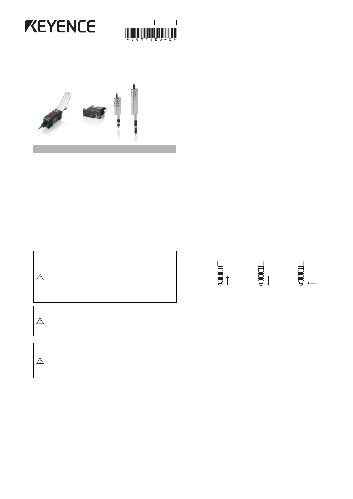
•
Do not apply weight greater than what is listed below to the spindle part.
Do not apply torque in the rotation direction. Otherwise the spindle may
break.
•
Although the sensor head has a waterproof structure, avoid using in
water or in the place where liquid such as water and oil may come into
contact with the sensor head.
30 N 100 N
●
Extending cable between amplifier and sensor head
Do not cut or extend the cable between the amplifier and the sensor
head. This may change the characteristics, causing the
specifications not to be satisfied.
●
Power su pply
•
Noise superimposed on the power supply may cause malfunction.
Be sure to use the DC stabilized power supply provided with an
insulation transformer.
•
In the case of a commercially available switching regulator, be
sure to ground the frame ground terminal or the ground terminal.
●
Effects of vibration
Vibrating the detection target may cause fluctuation in the indicated
value. In this case, extend the response time. This ensures more
accurate detection values.
●
Effects of magnetic fields
Contact by an external magnetic field to the sensor head will
influence the output. Avoid installing the GT-70A Series near motors
or other equipment and devices that generate strong magnetic
fields.
●
About dust protective boot
An optional dust protective boot is available (GT-H10: OP-78041, GTH22: OP-78042) for when the included dust protective boot has been
cracked or damaged. Please note that we cannot guarantee the
protection rating IP67 when the optional part is used. If you need a
guarantee for the protection rating IP67, replace the sensor head
itself.
1 N
1
GT-M-E
Page 2
CE Mark
Note
The GT-70A Series conforms to CE regulations in Europe.
The applicable regulations (EMC directive) are as follows.
EMI:EN61326,classA
EMS:EN61326
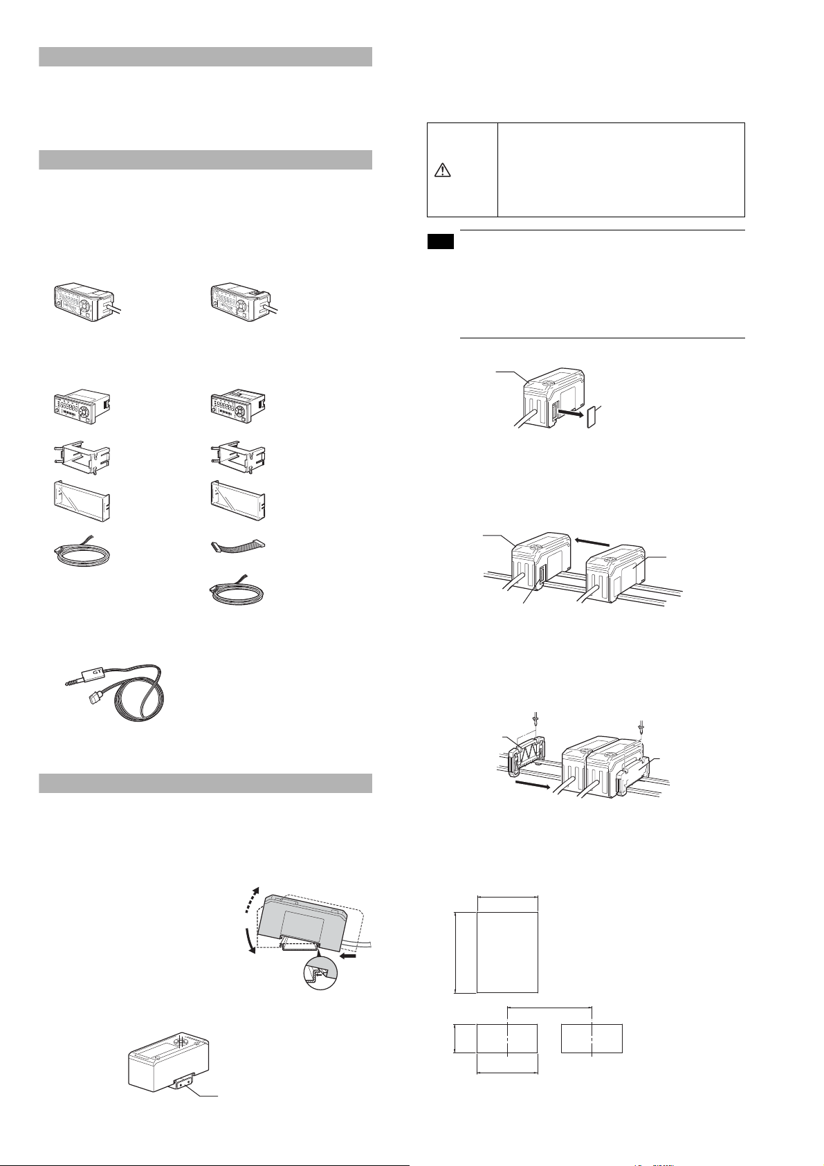
Package Contents
The product package of each model should include the following items.
Check that all items are included before use.
■
Amplifier parts
●
DIN rail mounting type
GT-71A/GT-71AP (Main unit)
P
H
H
I
B
H
P
P
G
O
C
A
L
C
LO
S
E
T
1
2
3
T
IM
SET
H
I
P
V
L
O
P
R
E
SE
T
M
O
D
E
S
E
R
IE
S
Amplifier x 1 Amplifier x 1Instruction manual x 1
●
Panel mounting type
GT-75A/GT-75AP (Main unit)
P‑H
HI
B‑H
P‑P
G
O
CA
LC
LO
1
2
3
T
I
M
H
I
Amplifier x 1
R
V
L
P
O
R
E
S
E
T
Panel mounting bracket x 1
Front protective cover x 1
Power cable (2 m) x 1
(Number of conductors: 8)
GT-72A/GT-72AP (Expansion unit)
P
H
H
I
B
H
P
-P
G
O
C
A
L
C
LO
S
E
T
1
2
3
T
I
M
SET
H
I
P
V
L
O
P
R
ES
E
T
M
O
D
E
S
E
R
I
E
S
GT-76A/GT-76AP (Expansion unit)
P‑
H
HI
B‑H
P‑
P
GO
C
A
L
C
L
O
1
2
3
TIM
HI
Amplifier x 1
RV
LO
P
R
E
S
E
T
Panel mounting bracket x 1
Front protective cover x 1
Expansion cable (50 mm) x 1
●
DIN rail mounting type (Expansion unit)
This section describes how to mount the DIN rail mounting type: GT72A/72AP (Expansion unit).
The expansion unit can only be used in addition to the main unit.
Up to nine expansion units can be added to one main unit.
• When adding an amplifier (expansion unit), be
sure the power of both main and expansion
units is OFF before operation. Mounting when
CAUTION
the power is ON may damage the equipment.
• Be sure to completely contact an expansion unit
to a main unit. Oblique or improper connections
may damage the equipment.
• When adding an expansion unit(s), be sure to use a
24 VDC power supply.
• An expansion unit of different output type cannot be
added (for example, an expansion unit of NPN output
cannot be added to a main unit of PNP output).
• An expansion unit of the DIN rail mounting type cannot
be added to a main unit of the panel mounting type.
1
Detach the expansion cover of the main unit.
Main unit
Expansion cover
2
Mount the expansion unit to be added to the DIN rail.
Refer to page 2, "DIN rail mounting type (Main unit)", for details
about how to mount.
3
Push and fix the expansion unit to the connector of the main
unit until it clicks.
Main unit
Expansion unit
Instruction manual x 1
■
Sensor head parts
Power cable (2 m) x 1
(Number of conductors: 6)
GT-H10/GT-H22 GT-H10L/GT-H22L
Sensor head x 1
Handling instruction x 1
We have taken all possible precautions in packaging; however, if any parts
are found to be defective or broken, please contact your nearest KEYENCE
sales office.
Mounting the Amplifier and Wiring
■
Mounting the amplifier
●
DIN rail mounting type (Main unit)
This section describes how to mount the DIN rail mounting type: GT71A/71AP (Main unit).
1
Fit the tab of the lower part of the
main unit to the DIN rail. While
inserting the main unit in the
direction of Arrow (1), push the body
down in the direction of Arrow (2).
2
To detach the amplifier, while
pushing the main unit in the
direction of Arrow (1), pull the body
up in the direction of Arrow (3).
When using a fixture (OP-76877), mount as shown below.
(3)
(2)
Connector
4
Mount the end units (OP-26751: a set of two pieces) on both
sides of the amplifiers (the main unit and the expansion unit),
then fix the end units with screws on the upper part of each
end unit (2 points x 2 units).
The mounting method of the end unit is the same as that of the
amplifier.
End unit
End unit
●
Panel mounting type (Main unit)
This section describes how to mount the panel mounting type: GT75A/GT-75AP (Main unit).
1
Create a panel opening for mounting referring to the
dimensions below.
(1)
X
+0.4
-0
21
45
(unit: mm)
X=24 x (Number of amplifier unit -1)+21
63 min.
GT-M-E
Fixture: OP-76877
45
2
Insert the main unit, back end first, into the opening of the
panel.
2
Panel cut dimension
Page 3
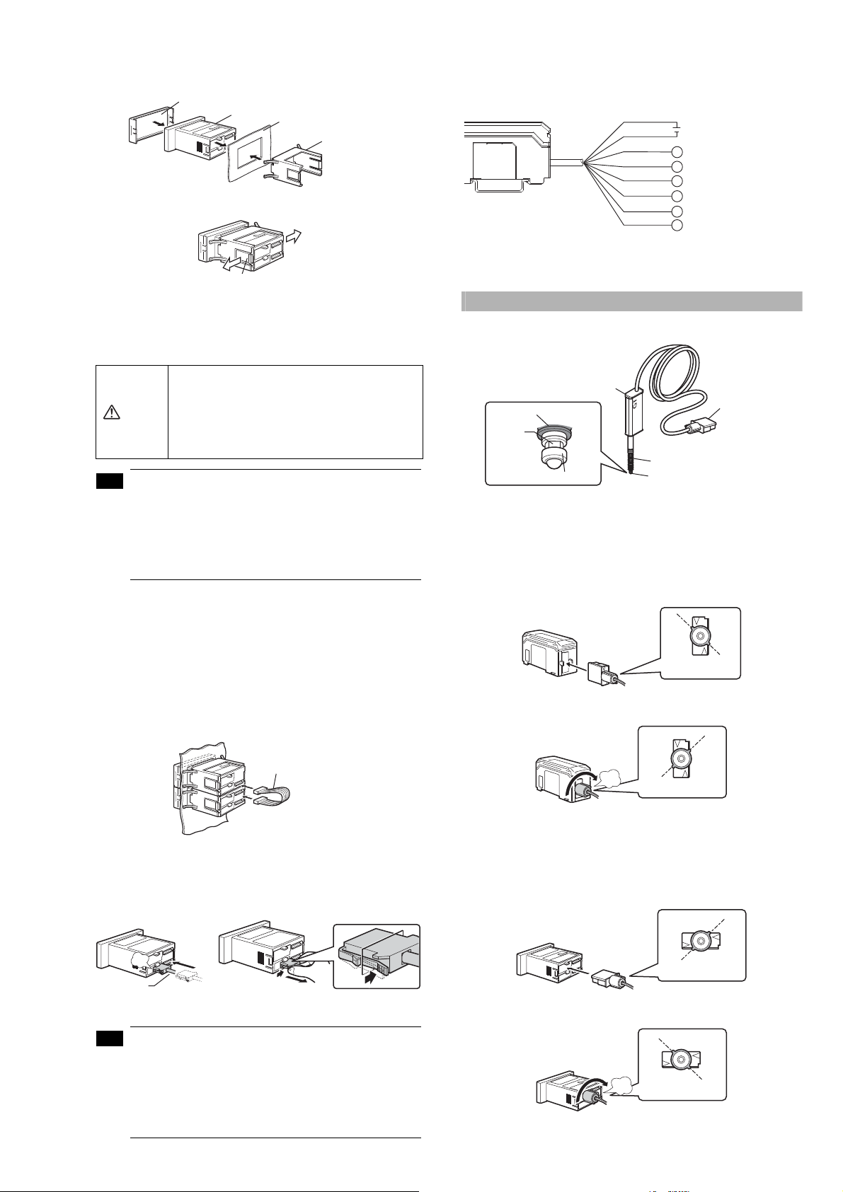
3
Note
Note
Insert the panel mounting bracket in the direction shown below
into the main unit from the back, then fit the front protective
cover to the main unit face.
Front protective cover
Amplifier
Panel
Panel mounting bracket
To detach the panel mounting bracket, pull it while pushing apart the
tabs provided on its both ends.
Ta b
●
Panel mounting type (Expansion unit)
This section describes how to mount the panel mounting type: GT76A/76AP (Expansion unit).
The expansion unit can only be used in addition to the main unit.
Up to nine expansion units can be added to one main unit.
•
Turn OFF the power before connecting the
expansion cable. Inserting or pulling the cable
when the power is turned ON may damage the
CAUTION
equipment.
• Be sure to completely connect the expansion
cable. Oblique or improper connections may
damage the equipment.
• When adding an expansion unit(s), be sure to use a
24 VDC power supply.
• An expansion unit of different output type cannot be
added (for example, an expansion unit of NPN output
cannot be added to a main unit of PNP output).
• An expansion unit of the panel mounting type cannot
be added to a main unit of the DIN rail mounting type.
1
Create panel openings for mounting according to the number of
expansion units to be mounted (the expansion unit to be added).
Refer to page 2, "Panel mounting type (Main unit)", for details about
panel cut dimensions.
2
Mount the amplifier (the expansion unit to be added) to the panel.
Refer to page 2, "Panel mounting type (Main unit)", for details about
how to mount.
3
Connect the amplifiers (the main unit and the expansion unit)
with an expansion cable.
●
I/O cable
The following illustrates the I/O power cable (also applicable to the
panel mounting type).
Refer to page 10 of this manual for details about I/O circuits.
*1
Brown
*1
Blue
Black
White
Gray
Pink
Violet
Pink/Violet
*1 Expansion units (GT-72A/72AP/76A/76AP) do not include brown and blue cables.
Power supply is 24 VDC when an expansion unit(s) is added.
*2 Default: BANK A input
*3 Default: TIMING input
12-24 VDC
HIGH output
LOW output
GO output
PRESET input
BANK A, or RESET input
BANK B, or TIMING input
Connecting and Mounting the Sensor Head
■
Names of parts of the sensor head
Indicator
Unlocked
Connection
plug
Dust protective boot
Spindle
Dust protective boot*
Contact point
* Not included in the GT-H10L and GT-H22L.
■
Connecting the sensor head
●
DIN rail mounting type
1
Switch the connection plug of the sensor head to "unlocked",
Contact point
then insert it into the connector on the side face of the
amplifier.
2
Turn the round end of the connection plug clockwise until it
clicks to switch to "locked".
*2
*3
Expansion cable
■
Wiring of amplifier
●
How to connect the power cable to the panel mounting type
The accessory power cable (I/O cable) must be connected to the
amplifier of the panel mounting type.
click
Power cable
(When connecting the power cable)
(When disconnecting the power cable)
• The number of power cable conductors is different
between the main unit and the expansion unit (Main
unit: 8 conductors, Expansion unit: 6 conductors).
• The power of the expansion unit is supplied through
the expansion cable being connected to the main
unit. If the I/O line of the expansion unit is not used,
cut the cable at the edge of the connector.
click
•
To detach the connection plug of the sensor head, follow the
Locked
above procedures in the opposite order.
●
Panel mounting type
1
Switch the connection plug of the sensor head to "unlocked",
then insert it into the connector on the back face of the
amplifier.
Unlocked
2
Turn the round end of the connection plug clockwise until it
clicks to switch to "locked".
click
•
To detach the connection plug of the sensor head, follow the
Locked
above procedures in the opposite order.
3
GT-M-E
Page 4

■
y
Note
Note
Note
Note
Note
Note
Note
Mounting the sensor head
●
Mounting directly to the jig
Before mounting the sensor head directory to the jig, create a hole
on the jig. Attach the sensor head using the optional Head mounting
bracket A (OP-76874).
Mounting illustration
Optional Head mounting
bracket A (OP-76874)
●
Mounting on the side of a surface
To mount the sensor head on the side face of a table, use the
optional Head mounting bracket B (OP-76875).
Mounting illustration
Optional Head mounting
bracket B (OP-76875)
Tightening sleeve Nut Mounting bracket
Tightening sleeve
Ke
1
Cut the jig to create a sensor head mounting hole referring to
Nut
wrench
the illustration below.
Tightening sleeve insertion side
C0.5 to C1.0
+0.027
φ10 G8( )
+0.005
2
Insert the tightening sleeve into the hole (from the recessed
5.5 to 11.3
Nut mounting side
side), and loosely tighten with the nut.
Tightening sleeve
Nut
Recessed side
Strongly tightening the nut without the sensor head
inserted may deform the tightening nut.
1
Insert the tightening sleeve into the mounting bracket from the
side with a depression, and loosely tighten with the nut.
Tightening sleeve
Mounting bracket
Nut
Notice the correct angle of the tightening sleeve.
• If the sleeve is inserted from the wrong side, the
sensor head cannot be secured.
• Strongly tightening the nut without the sensor head
inserted may deform the tightening nut.
2
Insert the sensor head into the tightening sleeve, and tighten
the nut with a wrench.
Wrench
Dust protective boot
Nut
3
Insert the sensor head in the tightening sleeve. While securing
the tightening sleeve with the included key wrench, tighten the
nut with a separate wrench.
Wrench
Key wrench
Dust protective boot
• Never apply tightening torque over 10 N•m
(The recommended tightening torque is 5 to 7 N•m).
• Care must be taken not to damage the dust protective
boot when tightening.
4
Rotate the dust protective boot so that the side line is straight.
Check with the spindle pushed in.
Never apply tightening torque over 10 N•m
(The recommended tightening torque is 5 to 7 N•m).
Use the wrench that fits the width of the nut.
3
Secure the sensor head with M4 screws.
M4 screws
• Never apply tightening torque over 1.4 N•m.
• Care must be taken not to damage the dust protective
boot when tightening.
4
Rotate the dust protective boot so that the side line is straight.
Check with the spindle pushed in.
GT-M-E
• If the dust protective boot is not straight, it becomes
easier to damage when the spindle is moved.
• If the end of the sensor head cable is bent repeatedly,
the cable may break.
• If the dust protective boot is not straight, it becomes
easier to damage when the spindle is moved.
• If the end of the sensor head cable is bent repeatedly,
the cable may break.
4
Page 5

How to detach the contact point
Note
Note
While securing the spindle with the accessory key wrench, detach the contact
point with pliers. Then attach a new contact point.
Spindle
Pliers
Contact point
4. HIGH setting value display
Displays/Sets an upper limit value of the range of the detection target.
5. LOW setting value display
Displays/Sets a lower limit value of the
6. Preset value setup display
Displays/Sets an arbitrary value to be added to or subtracted from
the display value.
range
of the detection target.
Zero-Point Correction
When you use this equipment for the first time or after the sensor head
is changed, be sure to correct the reference zero point.
Key wrench
• Detach the sensor head before replacing the contact point.
• When applying pliers to the contact point, be sure not to
rotate the main part and cover the contact point with a
cloth.
• Never apply tightening torque over 0.2 Nym when attaching a
contact point. Note that tightening torque 0.002 N
should be applied only when attaching a fluorine contained
resin contact (OP-80228). Do not use pliers, but place it with
your fingers. (Applying an adhesive, a thread locking agent, is
recommended to prevent the nut from getting loose.)
• Fix the roller contact point or the offset contact point
with the fixing nut in the same direction as in actual use.
Applying
recommended to prevent the nut from getting loose.
• Position the roller contact point carefully in the proper
direction. Care must be taken not to apply misdirected
force to the shaft.
an adhesive
, a thread locking agent, is
Cover the contact
point with a cloth
y
m or less
Amplifier display
■
Names of parts of the amplifier
Digital LED display
Detection level
indicator
[SET] button
Timing input indicator
■
Digital LED display
The main display during detection can be switched to the displays as
shown below by pressing the left/right Arrow buttons.
6. Preset value setup display
5. LOW setting value display
4. HIGH setting value display
* The display of 2. Calculated value display will appear only when an
expansion unit(s) is added.
1. P.V. value display ([P.V. = Present Value] Criterion value display)
Displays a value to be used for output judgment.
2. Calculated value display
Displays a calculated value such as a maximum or minimum value
of plural detection points created when adding an expansion unit(s)
(Displayed only when an expansion unit(s) is added).
3. R.V. value display ([R.V. = Raw Value] Raw value display)
Displays an actual detection value of the detection target.
Status indicator Arrow buttons
Preset indicator
HIGH position indicator/
LOW position indicator
1. P.V. value display
PV indicator
2. Calculated value display*
3. R.V. value display
[MODE] buttonBar LEDsBank indicator
• Zero-point correction is disabled when "------", "- FFFF"
or "FFFF" is displayed.
• Perform zero-point correction approx. every 1 million times
of use.
■
Setup using buttons
1
Set any main display and perform
the detection of the detection
target (master workpiece) to
serve as a reference for zeropoint correction.
Master workpiece
2
While the state of the master workpiece is being detected, press
the top/bottom Arrow buttons simultaneously.
After "PrESEt" has blinked several times on the digital LED display of
the amplifier, "0.000"* will appear.
The zero-correction is completed.
* When the preset function is set, the preset value will appear.
■
Setup using external input (Pink line)
1
Perform detection of the detection target (master workpiece) to
serve as a reference for zero-point correction.
2
Cause the pink line of I/O cable to short out.
Refer to page 10 of this manual for details about external input circuit
diagrams.
Setup of Range Limit Values
The range criteria values are an upper limit value (HIGH setting value)
and a lower limit value (LOW setting value). Setting these values enables
three types of judgment (display/output): above the upper limit (HIGH),
below the lower limit (LOW), and within the range (GO).
■
Manual setup of range limit values
The following shows how to set manually an upper limit value (HIGH
setting value) and a lower limit value (LOW setting value).
1
When in the main display, press the
left/right Arrow buttons until the HIGH
setting value display appears.
2
Enter an upper limit value (HIGH
setting value) with the top/bottom Arrow buttons.
3
Press the right Arrow button once to
cause the LOW setting value display
to appear.
4
Enter a lower limit value (LOW setting value) with the top/
bottom Arrow buttons.
The setup of range criteria values is completed.
To return to the P.V. value display, press the left/right Arrow buttons.
HIGH setting value display
LOW setting value display
5
GT-M-E
Page 6

Tips for Convenient Functions
This is a method for setting a range based on
the detection value of a master workpiece
when the master workpiece is available.
Note
Note
Note
Note
Note
■
Automatic setup of range criteria values
This function automatically sets an upper limit value (HIGH setting
value) and a lower limit value (LOW setting value).
For master workpieces, set by "tolerance tuning"; and for actual
works (good or defective), set by "two-point tuning".
Tolerance tuning
HIGH setting value
Tolerance tuning setting range
LOW setting value
Tolerance tuning is disabled when "------", "- FFFF" or
"FFFF" is displayed.
1
When in the main display, press the
left/right Arrow buttons until the P.V.
value display appears, then perform
detection of the master workpiece.
Tolerance tuning is enabled only when in the P.V. value
display.
2
Press the [SET] button while the master workpiece is being
detected to capture the detected value.
3
Press the upper/bottom Arrow buttons to enter a tolerance
tuning setting range.
4
Press the [SET] button to fix the tolerance tuning setting range.
After [SEt] blinks several times on the digital LED display of the
amplifier, the P.V. value display automatically appears.
Tolerance tuning is completed.
Two-point tuning
This is the method of setting the median values of the detected
good and/or defective workpieces as a range when the good
workpiece and HIGH/LOW defective workpieces are available.
Two-point tuning is disabled when "------" is displayed
as a P.V. value. When "- FFFF" or "FFFF" is displayed,
setting cannot be done accurately.
6
Detect the LOW defective workpiece and press the [SET]
button to capture the detected value.
The median value of this detected value
and the one captured in step 5 blinks.
LOW setting value is fixed.
Two-point tuning is completed.
Press the left/right Arrow buttons
to return to the P.V. value display.
■
Preset
This function displays the value obtained by adding or subtracting a
preset value to or from the detected value.
By using this function and the zero point correction function together,
you can set an arbitrary value as a reference point of the work.
■
Bank switching
By using the bank switching, you can register up to four patterns of
the HIGH setting value, LOW setting value and preset value,
respectively.
The bank switching is useful when there are multiple detection
targets since the pre-registered settings (four patterns) can be
easily switched.
■
Calculation with expansion unit
The GT-70A Series can calculate various values using the detected values
of multiple detection points such as the maximum value or the minimum
value when an expansion unit(s) is added (up to nine units).
Refer to pages 2 to 3 of this manual for details about how to add an
expansion unit.
The outline of the calculation function is shown below.
Calculation
No.
function
C1 Max. value
C2 Min. value
C3 Evenness
C4 Average
Reference
C5
difference
C6 Twist
C7 Curve
C8 Thickness
Displays the maximum value of the values
of the main unit and expansion unit(s)
Displays the minimum value of the values
of the main unit and expansion unit(s)
Displays a difference between the maximum
value and the minimum value of the values of
the main unit and expansion unit(s)
Displays the average obtained by dividing the
sum of the values of the main unit and expansion
unit(s) by the number of units connected
Displays a difference obtained by
subtracting the display value of the main
unit from that of each expansion unit
Displays a degree of twist obtained from
the values of four detection points
Displays a degree of curve obtained from
the values of three detection points
Displays a thickness obtained by
sandwiching the detection target between
the main unit and the expansion unit
The calculation function is selectable only on a main
unit with one or more expansion units added.
HIGH defective
Description
workpiece
Good
workpiece
HIGH
setting value
LOW
setting value
LOW defective
workpiece
Number of units
connected
2 to 10 units
2 to 10 units
2 to 10 units
2 to 10 units
2 to 10 units
4 units only
3 units only
2 units only
1
When in the main display, press the left/
right Arrow buttons until the HIGH
setting value display appears.
2
Detect the good workpiece and press the [SET] button to
capture the detected value.
"SEt" and the detected value blink alternately, and the value of the
good workpiece is fixed.
3
Detect the HIGH defective workpiece and press the [SET]
button to capture the detected value.
The median value of this detected value and the one captured in
step 2 blinks.
HIGH setting value is fixed.
4
Press the right Arrow button until the
LOW setting value display of the main
display appears.
5
Detect the good workpiece again and press the [SET] button to
capture the detected value.
GT-M-E
HIGH setting value display
LOW setting value display
■
Keylock
The keylock allows you to avoid erroneous button operation during
detection.
When the keylock is active, setup operations other than changing
the display are disabled.
The keylock setup can be set on the main display only.
●
Set the keylock
When in the main display, while pressing
the [MODE] button, press the upper
Arrow button for at least two seconds.
The keylock display will appear for several
seconds and then change to the main display.
●
Cancel the keylock
When in the main display, while pressing
the [MODE] button, press the upper
Arrow button for at least two seconds.
The keylock cancel display will appear for several
seconds and then change to the main display.
Keylock cancel display
6
Keylock display
Page 7

■
Note
Initial reset (Reset to the default state)
This function cancels all the functions you set and allows the
equipment to be reset to the default state.
• The initial reset can be set on the main display only.
• The initial reset cannot cancel "span adjustment results".
1
When in the main display, while
pressing the [MODE] button, press
the [SET] button five times.
"rSt.no" will appear.
2
Press the top/bottom Arrow buttons
to select "rSt.YES".
Detection mode (press and hold the [MODE] button in the main screen)
MODE
Standard
NG hold
Peak hold
Bottom hold
Peak to peak
Response time
3
Press the [MODE] button.
"rSt.End" will appear.
The initial reset is completed.
■
Switching the display unit
The display unit can be switched from the initial reset screen.
This section explains how to switch from "mm" display to "inch" display.
1
Display "rSt.YES" from the initial reset screen.
Refer to "Initial reset" for more details on how to display "rSt.YES".
2
Pressing the [MODE] button, press the [SET] button for 2
seconds or more.
3
Use the up and down Arrow button to
select "inch".
4
Press the [MODE] button.
"rSt.End" will appear.
Switching the display unit is completed.
Setting Mode Display
■
Function setting mode
You can set the following functions in the function setting mode.
No.
Item Description
Detection mode
Response
time
Timing type
Self timing
level
Select the detection mode.
Longer response time makes the average
data time longer, which stabilizes the value.
For the timing input, select "External timing"
or "Self timing (internal timing)".
When the self timing is selected in , set
the self timing level.
When the value rises above (or falls below) the
Self timing
delay type
User specified
delay time
Static hold
delay stability
criterion
Static hold
delay stability
width
Calculation
mode
self timing level with "Std" selected in ,
select "Fix the criterion value when the setting
time is elapsed" or "Fix the criterion value after
the display value is stabilized (static hold)".
Set the delay time when "Fix the criterion value
when the setting time is elapsed" is selected in .
Set the reference of stability criterion when "Fix
the criterion value after the display value is
stabilized (static hold)" is selected in .
Enter the optional numerals when USEr (user
specification) is selected in .
Set the calculation method when an
expansion unit(s) is added. *The calculation
mode will appear only when an expansion
unit(s) is added.
MODE
Display for entering the setting value
Timing type
Available to set only when any of Std, P-H and b-H is selected in [ Detection mode].
MODE
External timing input
Rising self
Falling self
Self timing level
Available to set only when item other than t-in is selected in [ Timing type].
MODE
Display for entering the setting value
Self timing delay type
Available to set when the following conditions are provided.
•
Std is selected in [ Detection mode].
•
Item other than t-in is selected in [ Timing type].
MODE
Static hold
Delay timer
User specified delay time
Available to set only when t.d is selected in [ Self timing delay type].
MODE
Display for entering the setting value
Static hold delay stability criterion
Available to set only when Stb.d is selected in [ Self timing delay type].
MODE
Default
User
Static hold delay stability width
Available to set only when USEr is selected in [ Static hold delay stability criterion].
Display for entering the setting value
7
MODE
GT-M-E
Page 8

OFF
Calculation mode
*The calculation mode will appear only when an expansion unit(s) is added.
Max. value
Min. value
Evenness
Average
Reference difference
Tw is t
Curve
Thickness
MODE
MODE
Normal
Measurement direction change
(press and hold the [MODE] + [SET] buttons in the main screen)
Reverse
Display for entering the setting value
Lever ratio
MODE
N.O.
Output format
N.C.
MODE
Display for entering the setting value
Number of display digits
MODE
Hysteresis
Display for entering the setting value
Input line function 1
Input line function 2
MODE
MODE
Bank A
Reset input
■
Basic setting mode
You can set the following functions in the basic setting mode.
No.
Item Description
Measurement
direction
change
Set the "Normal" or "Reverse" when the
spindle of the sensor head is inserted.
Lever ratio Set the ratio of the detected value.
Output format
Number of
display digits
Set "ON (N.O.)" or "OFF (N.C.)" for output
judgment.
Set the number of display digits.
Hysteresis Set the hysteresis value.
Input line
function 1
Input line
function 2
Set the input line function 1 (Violet).
Set the input line function 2 (Pink/Violet).
MODE
Timing input
Bank B
■
Additional function setting mode
You can set the following functions in the additional function setting mode.
No.
Item Description
Preset
memory
Power-saving
function (ECO)
Jam detection
function
Check point
setting
Display filter
function
Set the memory status for "zero-point
correction".
To decrease the power consumption or not to
display the numerical value, set this function.
When the spindle does not return due to an
undetected event in external timing input, set
to detect such an event as an error.
Set the point to detect as an error for .
Set the filter to stabilize the display.
Preset memory (press and hold the [MODE] + left buttons in the main screen)
MODE
YES
NO
GT-M-E
Power-saving function
MODE
OFF
ECO Half
ECO All
Jam detection function
Available to set only when t-in is selected in [ Timing type].
MODE
OFF
ON
User
8
Page 9

Jam detection teaching
Available to set when USEr is selected in [ Jam detection function].
Reference position
fixed
Check point setting
Available to set when USEr is selected in [ Jam detection function].
MODE
Display for entering the setting value
Display filter function
MODE
ON
OFF
■
Calibration setting mode
You can set the following functions in the calibration setting mode.
No.
Item Description
Calibration Set the calibration function.
2nd point
target value
Set the target value of the span adjustment
(2nd point).
Calibration function setting
(press and hold the [MODE] + right buttons in the main screen)
MODE
Default
Adjustment
Error message
Error display Cause Corrective action
*1 If not recovered by this action, there may be a possibility of failure or
permanent damage. In this case, change the amplifier unit.
The sensor head
cable is disconnected.
• The sensor head
cable is broken.
• The sensor head is
damaged.
An overcurrent flows
in the output line.
Failed to write/read
data.
Spindle movement is
not detected
The value fell below (rose
above) the timing level
during the delay time.
When setting the
internal timing, detection
was completed when the
value fell below (rose
above) the timing level
before the criterion value
(P.V. value) is fixed.
Contact between the
amplifiers is lost.
In the case of using the
calculation function,
the number of the
expansion unit when
the power is turned ON
differs from the number
of the expansion unit in
the memory of the
main unit when the
calculation is set.
• When using the
reference difference
(rEF) calculation
function, an error
occurred in the main
unit.
• When using other
than the reference
difference (rEF)
calculation function,
an error occurred in
an expansion unit.
Connect the sensor head to
the amplifier.
Change the sensor head.
• Check that the load is within
the rating.
• Check that the output line is
not contacting other lines and
frames.
Reboot the equipment and
perform initial reset.
• If something is caught in the
spindle, causing the spindle not to
move, change the sensor head.
• Check the external timing input.
(Press the SET button to reset.)
Change the delay timer time
setting. (Press the SET button
to reset.)
The value should not fall below
(rise above) the timing level
before the criterion value is
fixed. Alternatively, lengthen
the static hold delay stabilizing
amplitude so that the criterion
value can be easily fixed.
After turning OFF the power,
check the connection between
the amplifiers.
• Reset the calculation mode
or perform the initial reset of
the main unit.
• After turning OFF the power,
check the connections
between the amplifiers.
Check each main/expansion
unit for the cause of the error.
*1
1st point detection/capture
Available to set only when AdJ is selected in [ Calibration function setting].
Blink alternately
Detect 1st point
Capture the detection value
*Target value for the first point is the PrESEt value.
2nd point target value setting
MODE
Display for entering the setting value
2nd point detection/capture
Blink alternately
Detect 2nd point
Capture the detection value
Specifications
■
Sensor head
Model GT-H10 GT-H22 GT-H10L GT-H22L
Detecting range 10mm 22mm 10mm 22mm
Mechanical response
(at an ambient temperature of 23°C)
Repeat accuracy
*1
When installed
facing down
Measuring
Force
When installed
*2
sideways
When installed
facing up
Ambient
Environmental
resistance
temperature
Relative
humidity
Protective construction IP67
Main unit cover
Indicator Polyalylate
Material
Dust protective boot
Contact point SUS440C
Cable PVC
*3
Weight
*1
The read value at the detection center under an ambient temperature
of 23°C and a response time of 100 ms (default state).
*2 At the center of the movable range of the sensor head installed.
Varies according to the mounted condition of the dust protective boot.
*3 The connector cable (2 m) is included.
10 Hz max.
8 Hz max. 7 Hz max. 5 Hz max.
3 µm 8 µm 3 µm 8 µm
1.0 N 1.5 N 0.3 N 0.35 N
0.9 N 1.4 N 0.25 N 0.3 N
0.8 N 1.3 N 0.2 N 0.25 N
-10°C to +55°C
35 to 85%RH
SUS430
NBR
Approx.
115 g
Approx.
135 g
Approx.
115 g
Approx.
135 g
9
GT-M-E
Page 10

■
Brown
*1
Blue
*1
Pink, Violet, Pink/Violet
*3
Black (HI output)
White (LO output)
Gray (GO output)
12-24 VDC
*2
5-40 VDC
5-40 VDC
5-40 VDC
0 V
External input
Load
Load
Load
Input circuit
Overcurrent
protection circuit
Main circuit
*1 Brown and blue are available for main units (GT-71A/71AP/75A/75AP) only.
Not available for expansion units (GT-72A/72AP/76A/76AP).
*2 When expanded, 24 VDC.
*3 Refer to external input circuit diagram for details about external input.
Brown
*1
Blue
*1
Pink, Violet, Pink/Violet
*3
Black (HI output)
White (LO output)
Gray (GO output)
12-24 VDC
*2
0 V
External input
Load
Load
Load
*1 Brown and blue are available for main units (GT-71A/71AP/75A/75AP) only.
Not available for expansion units (GT-72A/72AP/76A/76AP).
*2 When expanded, 24 VDC.
*3 Refer to external input circuit diagram for details about external input.
Input circuit
Overcurrent
protection circuit
Main circuit
Amplifier
*1
Ty pe
Main unit/
Expansion unit
Mounting type
Model
NPN output GT-71A GT-72A GT-75A GT-76A
PNP output GT-71AP GT-72AP GT-75AP GT-76AP
Supply voltage
*3
DIN rail mounting Panel mounting
Main unit
*2
Expansion
unit
Main unit
12 to 24 VDC, Ripple (P-P): 10% max.
Class 2
Expansion
unit
Display range -99.999 to 999.999
Display resolution 1 µm
Sampling rate 2000 times/sec
Normal mode 24 V: 1200 mW (50 mA) max.
Current consumption
12 V: 1140 mW (95 mA) max.
Eco mode 24 V: 840 mW (35 mA) max.
12V: 600mW (50mA) max.
Response time
Control
output
(HIGH/
GO/LOW)
NPN
PNP
HSP(1.5 ms), 5 ms, 10 ms, 100 ms,
500ms, 1s, 5s
NPN open collector 40 V 50 mA max.
Residual voltage: 1 V max.
PNP open collector 30 V 50 mA max.
Residual voltage: 1 V max.
Non-voltage input (contact/non-contact
Control
input
Environmental
resistance
Timing input
Preset input
Bank input
Reset input
Ambient
temperature
Relative
humidity
Vibration
inputs)
Input time: 2 ms min.
Non-voltage input (contact/non-contact
inputs)
Input time: 20 ms min.
-10 to +55°C (No freezing)
35 to 85%RH (No condensation)
10 to 55 Hz, Horizontal amplitude: 1.5 mm,
2 hours each in X, Y, and Z axis
Main unit cover: Polycarbonate
Material
Keytop : Polyacetal
Front sheet: Polycarbonate
Cable : PVC
GT-71A(AP), 72A(AP): Approx. 110 g
(Including a power cable)
Weight
GT-75A(AP), 76A(AP): Approx. 110 g
(Including a panel mounting bracket, front
protective cover, power cable)
*1 When adding an expansion unit(s), be sure to use the end units
(OP-26751).
*2 Maximum number of units connectable is 10 units including 1 main
unit and 9 expansion units. When expanded, the output current of
each unit should be 20 mA max.
*3 When expanded, the power supply should be 24 VDC.
Circuit diagram
■
I/O circuit diagram
GT-71A/GT-72A/GT-75A/GT-76A
■
External input circuit diagram
GT-71A/GT-72A/GT-75A/GT-76A
DC5V
Main
circuit
(Short circuit current: 1 mA max.)
*1 Blue is available for main units (GT-71A/71AP/75A/75AP) only.
Not available for expansion units (GT-72A/72AP/76A/76AP).
Pink: Preset input
Violet: Bank A input/ Reset input change
Pink/Violet: Bank B input/ Timing input change
*1
Blue
GT-71AP/GT-72AP/GT-75AP/GT-76AP
12 V~24 VDC
*1
Brown
Main circuit
(Short circuit current: 2 mA max.)
*1 Brown is available for main units (GT-71A/71AP/75A/75AP) only.
Not available for expansion units (GT-72A/72AP/76A/76AP).
Pink: Preset input
Violet: Bank A input/ Reset input change
Pink/Violet: Bank B input/ Timing input change
Warranty
KEYENCE warrants its Products to be free from defects of material and
workmanship and will, without charge, replace or repair (at KEYENCE's
sole option) any Products found defective upon inspection at its factory,
or other designated point provided the equipment has been returned,
transportation prepaid, within one year from the date of shipment.
Warranty is specifically at the factory. Any on-site service will be
provided at the sole expense of the Purchaser at standard field service
rates. All associated equipment must be protected by properly rated
electronic/electrical protection devices.
KEYENCE shall not be liable for any damage due to improper
engineering, installation, interfacing, use, modification or any action not
in accordance with this instruction manual. Proper installation,
operation and maintenance of the product in accordance with this
instruction manual become the responsibility of the user upon receipt of
the Product. The user shall indemnify KEYENCE and hold KEYENCE
harmless from any liability or damage whatsoever arising out of any
action not in accordance with this instruction manual. Components
which wear are not warranted.
OTHER THAN AS STATED HEREIN, THE PRODUCTS ARE
PROVIDED WITH NO OTHER WARRANTIES WHATSOEVER.
ALL EXPRESS, IMPLIED, AND STATUTORY WARRANTIES,
INCLUDING, WITHOUT LIMITATION, THE WARRANTIES OF
MERCHANTABILITY, FITNESS FOR A PARTICULAR PURPOSE,
AND NON-INFRINGEMENT OF PROPRIETARY RIGHTS, ARE
EXPRESSLY DISCLAIMED. IN NO EVENT SHALL KEYENCE AND
ITS AFFILIATED ENTITIES BE LIABLE TO ANY PERSON OR ENTITY
FOR ANY DIRECT, INDIRECT, INCIDENTAL, PUNITIVE, SPECIAL
OR CONSEQUENTIAL DAMAGES (INCLUDING, WITHOUT
LIMITATION, ANY DAMAGES RESULTING FROM LOSS OF USE,
BUSINESS INTERRUPTION, LOSS OF INFORMATION, LOSS OR
INACCURACY OF DATA, LOSS OF PROFITS, LOSS OF SAVINGS,
THE COST OF PROCUREMENT OF SUBSTITUTED GOODS,
SERVICES OR TECHNOLOGIES, OR FOR ANY MATTER ARISING
OUT OF OR IN CONNECTION WITH THE USE OR INABILITY TO
USE THE PRODUCTS, EVEN IF KEYENCE OR ONE OF ITS
AFFILIATED ENTITIES WAS ADVISED OF A POSSIBLE THIRD
PARTY'S CLAIM FOR DAMAGES OR ANY OTHER CLAIM AGAINST
THE PURCHASER. No representation or warranty, express or implied,
made by any sales representative, distributor, or other agent or
representative of KEYENCE which is not specifically set forth herein
shall be binding upon KEYENCE. In some jurisdictions, some of the
foregoing warranty disclaimers or damage limitations may not apply.
GT-71AP/GT-72AP/GT-75AP/GT-76AP
GT-M-E
Copyright (c) 2007 KEYENCE CORPORATION. All rights reserved.
1825E 0099-2 96M1825 Printed in Japan
10
 Loading...