

Page 1
Multipurpose Digital Contact Sensor
457GB
Setup Functions
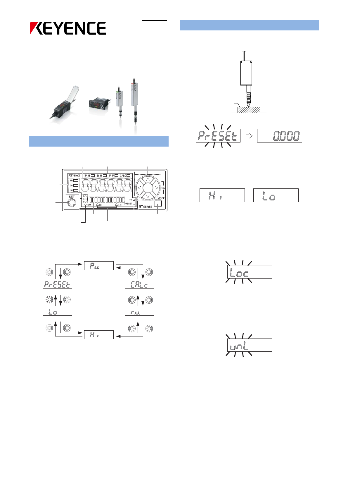
Set the current value to “0”
1. Set the master target which should be “0”.
GT-70A
Series Setting Guide
2. Press the [PRESET] button.
Amplifier Display
Names of the part of the amplifier
Detection level
indicator
[SET] button
Timing input indicator
Digital LED Display
The main display can be switched by pressing the left/right arrow
buttons.
Digital LED display Status indicator Arrow buttons
Bank indicator
Bar LEDs
High position indicator/
Low position indicator
Preset indicator
[MODE] button
PV indicator
3. The current value would be set to “0”.
Set the HIGH and LO tolerance.
1. Press the left/right arrow buttons until the [HIGH]/[LO] setting
display appears.
2. Input the HIGH or LO tolerance by pressing the up/down arrow
buttons.
3. The HIGH and LO tolerance would be set.
Setting the Key Lock
1. Press the MODE and the up arrow button for at least 2 seconds.
Master workpiece
HIGH setting value display LOW setting value display
1. P.V. value display
6. Preset value setup display
5. LOW setting value display
4. HIGH setting value display
P.V. : Displays a value used for output judgment.
Calc : Displays a calculated value when used.
R.V. : Displays the raw, actual detection value.
HI : Displays the HIGH setting value.
LOW : Displays the LOW setting value.
PRESET : Displays the value which would be set when the [PRESET]
button is pressed.
2. Calculated value display
3. R.V. value display
2. The Key Lock display would appear.
Canceling the Key Lock
1. When the Key Lock is set, press the MODE and the up arrow button
for at least 2 seconds.
Keylock display
2. The Key Lock would be cancelled.
Keylock cancel display
1
Page 2
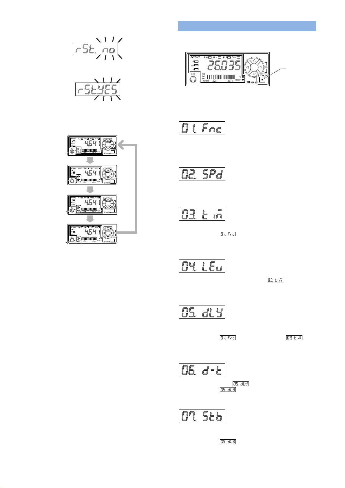
Initializing the sensor
1. Press the SET button 5 times while pressing the MODE button.
2. “rSt.no” would appear, press the up/down arrow button and select
“rSt.YES”.
Function setting mode
How to enter the Function setting mode
1. Press the MODE button for at least 2 seconds.
[MODE] button
3. Press the MODE button. The sensor would be initialized.
Changing the bank (program)
1. Press the up/down arrow button while pressing the MODE button.
<Bank 0 is selected>
The bank indicator is
turned off.
<Bank 1 is selected>
The bank indicator 1
is lit in green.
<Bank 2 is selected>
The bank indicator 2
is lit in green.
<Bank 3 is selected>
The bank indicator 3
is lit in green.
While holding down
[MODE], press [Up].
While holding down
[MODE], press [Up].
While holding down
[MODE], press [Up].
While holding
down [MODE],
press the [Up].
2. The bank (program) would be switched to another one. Each bank
(program) will have an own HIGH/LOW/PRESET setting value.
Main screen (P.V. value display)
2. Press the left/right arrow button and select the function number.
01 Detection mode
Set the detection mode from [Standard], [NG hold], [Peal hold], [Bottom
hold] or [Peak to peak] mode.
02 Response time
Set the response speed.
03 Timing type
Set the timing time from [External input], [Rising edge] or [Falling edge].
Only available when is set to [Standard], [Peal hold] or
[Bottom hold].
04 Self timing level
Set the self timing level. Only available when is set to [Rising
edge] or [Falling edge].
05 Self timing delay type
2
Set how the value is decided after the self timing is input, from [Static
hold] or [Delay timer].
Only available when is set to [Standard], and is set
to [Rising edge] or [Falling edge].
06 User specified delay time
Set the delay time used for .
Only available when is set to [Delay timer].
07 Static hold delay stability criterion
Set how the decide the range, which is used to judge if the value is
stable or not, from [Default] or [User].
Only available when is set to [Static hold].
Page 3

08 Static hold delay stability width
A
dditional function setting mode
Set the range which is used to judge if the value is stable or not.
Only available when is set to [User].
How to enter the Function setting mode
1. Press the MODE and left arrow button at the same time for at least
Basic setting mode
How to enter the Function setting mode
1. Press the MODE and SET button at the same time for at least 2
seconds.
[SET]
button
[MODE]
button
2. Press the left/right arrow button and select the function number.
10 Measurement direction change
Main screen (P.V. value display)
Set how the value moves, when the spindle is pressed, from [Normal]
or [Reverse].
11 Measurement direction change
Set a number if the value has to be multiplied.
12 Output format
2. Press the left/right arrow button and select the function number.
20 Store preset value
Set if the preset data should be memorized or not.
21 Power save function
Select from [OFF], [ECO Half] or [ECO all].
22 Jam detection function
Set to use the Jam detection function. Jam detection function checks if
the spindle still has the ability to fully extend. Only available when
23 Check point setting
2 seconds.
Main screen (P.V. value display)
is set to [External input].
Left arrow key
[MODE] button
Set the output mode from [N.O.] or [N.C.].
13 Displayed number of digits
Set the number of digits of the value.
14 Hysteresis
Set the hysteresis value.
15 Input line function 1
Set the function for input line 1(purple). [Bank A input] or [Reset input]
can be selected.
16 Input line function 2
Set the reference position which is used to check if the spindle is fully
extended. Only available when is set to [User].
24 Display filter function
Set t o u se the Di sp lay fi lt er function. Di splay fi lter funct io n m akes
the response speed of the display slow, to show it stable.
Set the function for input line 2(pink/purple). [External timing input] or
[Bank B input] can be selected.
1114 -1
3
 Loading...