


2CH AC VOLTMETER
VT-185/VT-186/VT-187
SERVICE MANUAL
KENWOOD TMI CORPORATION
© 1998-8/B51-1134-00 (K/K)
VT-187 only
HANDLE : (K01-0564-08)
HANDLE COVER : (B09-0410-08)
FRONT PANEL
VT-185: (A63-0303-08)
VT-186: (A63-0304-08)
VT-187: (A63-0305-08)
PUSH KNOB (K24-3015-08)
ROTARY KNOB (K21-0960-08)
SIDE PANEL (A13-2254-08)
RUBBER FOOT (J02-0543-08)

VT-185/VT-186/VT-187
WARNING
The following instructions are for use by qualified personnel only. To avoid electric shock, do not perform any servicing other than contained in the operating instructions unless you are qualified to do so.
|
CONTENTS |
SPECIFICATIONS .......................................................................................................... |
3 |
SAFETY .......................................................................................................................... |
4 |
CIRCUIT DESCRIPTION ................................................................................................ |
5 |
BLOCK DIAGRAM .......................................................................................................... |
6 |
ADJUSTMENT ................................................................................................................ |
7 |
PARTS LIST (UNIT)...................................................................................................... |
10 |
PARTS LIST (ELECTRICAL) ........................................................................................ |
11 |
SCHEMATIC DIAGRAM ............................................................................................... |
16 |
P.C. BOARD ................................................................................................................. |
26 |
2

VT-185/VT-186/VT-187
SPECIFICATIONS
ITEMS |
VT-185 |
VT-186 |
VT-187 |
Meter Section
Measurable voltage |
1mV to 300mV in ranges: |
0.3mV to 100mV in 12 ranges : |
|
1, 3, 10, 30, 100, 300mV, |
0.3, 1, 3, 10, 30, 100, 300mV, |
|
1 , 3, 10, 30, 100, 300V |
1, 3, 10, 30, 100V full scale. |
|
full scal. |
|
dB |
-80 to +50dB (0dB=1V) |
-90 to +40dB (0dB=1V) |
dBm |
-80 to +52dBm |
-90 to +42dBm |
|
(0dBm=1mW at 600Ω) |
(0dBm=1mW at 600Ω) |
Error |
|
Within ±3% of full scale at 1kHz |
Frequency response |
±10% at 5Hz to 1MHz, ±5% at 10Hz to 500kHz, |
|
|
±3% at 20Hz to 200kHz and ±2% at 30Hz to 100kHz |
|
|
as response to 1KHz response. |
|
Input impedance |
10MΩ ±5%, with less than 45pF parallel capacitance. |
|
Max. input voltage |
500V(DC +AC peak) |
|
|
1V to 300V range |
500V(DC +AC peak) 1V to 100V range |
|
100V(DC +AC peak) |
100V(DC +AC peak) 0.3mV to 300mV range |
|
1mV to 300mV range |
|
Stability |
Within ±0.5% of full scale for ±10% line voltage fluctuation |
|
Residual Voltage |
Less than 20 V with input |
Less than 30 V with input shorted on 0.3mV range |
|
shorted on 1mV range |
|
|
|
|
Crosstalk Individual |
Less than -80dB with other input terminated with 600Ω |
|
Crosstolk Interlock |
Less than -50dB with other input terminated with 600Ω |
|
Amplifier Section
Gain |
Approx. 60dB |
|
Approx. 70dB |
Output voltage |
|
1Vrms (full scale) ±20% |
|
Output resistance |
|
600Ω ±20% at 1kHz |
|
Distortion |
Less than 1% at full scale |
|
Less than 1% at full scale |
|
(Rated by signal to noise ratio |
|
|
|
(Rated by signal noise ratio in 1mV and 1V ranges) |
||
|
in 0.3mV, 1mV and 1V range). |
||
|
|
|
|
Signal to noise ratio |
Over 40dB at full scale. (Over 30dB at 0.3mV range) |
||
|
|
|
|
Frequency response |
|
Within |
± 3dB at 5Hz to 500kHz |
Environmental
Coefficient |
±: 0.08%/°C |
|
|
Temperature |
Within specifications : |
10 to 40°C |
|
|
Full operation |
: |
0 to 50°C |
Relative humidity |
Less than 80% |
||
Maximum altitude |
|
2000m |
|
Overvoltage Category |
|
¿ |
|
Pollution Degree |
|
2 |
|
Power Supply Section
Line voltage |
|
100/120/220/230 Vac ±10% 50/60Hz |
|
|
Power consumption |
|
Max. 11W |
|
|
Dimensions |
|
128 (128) X 190 (210) X 239 (269) |
|
|
W X H X D (mm) |
|
Value in ( ) include protrusions |
|
|
Net Weight |
|
Approx. 3.1 kg |
|
Approx. 3.2 kg |
Accessories |
|
|
|
|
Power cable |
|
1 pc. |
|
|
Input cable |
|
CA-41p 2 pcs. |
|
|
Replacement fuse |
|
1 pc. |
|
|
Instruction manual |
|
1 copy |
|
|
Adjust driver |
|
1 pc. |
|
|
Regulatory Information (VT-186 only) |
|
|
|
|
EMI |
|
EN55011 (1991) CLASS B |
|
|
Immunity |
|
IEC801-2 (1991) 8kVAD |
|
|
|
|
IEC801-3 (1984) 3V/M |
|
|
|
|
IEC801-4 (1988) |
|
|
7The above specifications are subject to charge without noise.
3
VT-185/VT-186/VT-187
SAFETY
SAFETY
Before connecting the instrument to a power source, carefully read the following information, then verify that the proper power cord is used and the proper line fuse is installed for power source. The specified voltage is shown on the rear panel. If the power cord is not applied for specified voltage, there is always a certain amount of danger of electric shock.
Line voltage
This instrument operates using ac-power input voltages that 100/120/220/230 V at frequencies from 50 Hz to 60Hz.
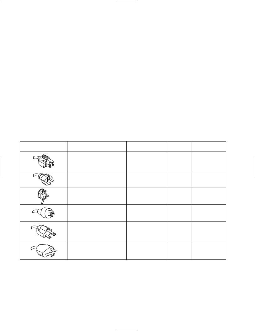
Power cord
The ground wire of the 3-wire AC power plug places the chassis and housing of the instrument at earth ground. Do not attempt to defeat the ground wire connection or float the instrument ; to do so may pose a great safety hazard. The appropriate power cord is supplied as an option that is specified when the instrument is ordered.
The optional power cords are shown as follows in Fig.1
Line fuse
The fuse holder is located on the rear panel and contains the line fuse. Verify that the proper fuse is installed by replacing the line fuse.
Voltage conversion
This instrument can be operated from 100 to 230V, 50/60Hz power source.
Use the following procedure to change from 100 to 230V operation or vice versa.
1.Remove the fuse holder.
2.Replace fuse F1 with a fuse of appropriate value.
3.Reinsert it for appropriate voltage range.
4.When performing the reinsertion of fuse holder for the voltage conversion, the appropriate power cord should be used. (See fig.1)
Plug configuration |
power cord and plug type |
Factory installed |
Line cord |
Parts No. for |
|
instrument fuse |
plug fuse |
power cord |
|||
|
|
||||
|
North American |
0.2A, 250V |
|
|
|
|
120 volt/60 Hz |
slow blow |
None |
E30-1983-08 |
|
|
Rated 15 amp |
5x20mm |
|||
|
|
|
|||
|
(12 amp max ; NEC) |
|
|
|
|
|
Universal Europe |
0.1A, 250V |
None |
|
|
|
230 volt/50 Hz |
slow blow |
E30-1982-08 |
||
|
Rated 16 amp |
5x20 mm |
|
|
|
|
U.K. |
0.1A, 250V |
5A |
|
|
|
230 volt/50 Hz |
slow blow |
E30-1985-08 |
||
|
Type C |
||||
|
Rated 5 amp |
5x20 mm |
|
||
|
|
|
|||
|
Australian |
0.1A, 250V |
None |
|
|
|
240 volt/50 Hz |
slow blow |
E30-1986-08 |
||
|
Rated 10 amp |
5x20 mm |
|
|
|
|
North American |
0.2A, 250V |
|
|
|
|
240 volt/60 Hz |
slow blow |
None |
– |
|
|
Rated 15 amp |
5x20mm |
|||
|
|
|
|||
|
(12 amp max ; NEC) |
|
|
|
|
|
Switzerland |
0.3A, 250V |
|
– |
|
|
230 volt/50Hz |
slow blow |
None |
||
|
Rated 10 amp |
5x20 mm |
|
|
Fig.1 Power Input Voltage Configuration
4

VT-185/VT-186/VT-187
CIRCUIT DESCRIPTION
The voltage or sentence in parenthes is applicable in case of the "VT-185".
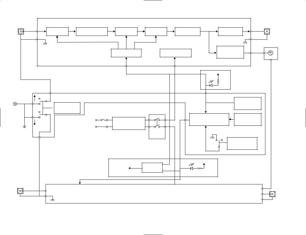
In studying the operation of each circuit in voltmeter please refer to "BLOCK DIAGRAM".
General
A Signal voltage to be measured, which is input from the INPUT connector, is passed through the First Attenuator and is converted to a low impedance by the Impedance Convertor. The impedance-converted signal is normalized, or further attenuated in proportion to 1mVrms fullscale value through the Second and Third Attenuator. The normalized signal is magnified 20-fold by the Main Amplifier and is fed to the Output Amplifier and the Absolute-Mean Value Detector.
The Output Amplifier magnifies the signal 50-fold and feeds to the OUTPUT connector. The Absolute-Mean Value Detector converts the signal from the Main Amplifier to DC current in proportion to the absolute mean value. The converted signal activates the Meter.
The Attenuator Control encodes the signal led from the RANGE selector to generate an Attenuator Control signal. This signal controls the First, Second and Third Attenuator to set the sensitivity corresponding to each range.
The Power Supply feeds to the functional circuit ±5V DC voltages stabilized by its IC regulator.
Description of Functional Circuit
1) First Attenuator
A potential divider acts as an attenuator. The amount of attenuation is switched in two steps by relay contacts:0dB and -60dB.
2) Impedance Converter
A FET differential input Amplifier acts as an impedance converter with 0dB(10dB) gain, which converts the First Attenuator output signal to a sufficiently low impedance and feeds of the Second Attenuator.
6) Output Amplifier
A wideband, non-inverting differential amplifier acts as an output amplifier, which has 50-fold gain and 600Ω output impedance. The output signal level is 1Vrms for fullscale read on the Meter, and works stable even for capacitive loads.
7) Absolute-Mean Value Detector
An absolute-mean value detector comprised of a high through-rate and high gain amplifier, which has very good linearity by negative feedback from the current flowing through the Meter load. In switching, this provides a sufficiently wide frequency band so that the high frequency phase compensation circuit is reset.
8) Attenuator Control
A logic control circuit comprised of a diode matrix and output buffer transistors. This encodes a 12-bit signal from the RANGE selector switch to 6-bit signals, which control the First, Second and Third Attenuator. The remote control connector is connected to this circuit.
9) Power Supply
The power source circuit supply ±5V DC from the AC input, which contain a silicon diode bridge for full-wave rectification, high-capacitance electrolytic capacitors for smoothing, and an IC regulator stabilization.
10) CH1/CH2 Rotary Switch
A 12-contact rotary switch for setting a desired channel 1 and 2 measurable voltage range. This feeds a signal corresponding to the range into the Attenuator Control.
11) CH2 Rotary Switch
A 12-contact rotary switch for setting a desired channel 2 measurable voltage range. This feeds a signal corresponding to the range into the Attenuator Control.
3) Second Attenuator
A resistance divider acts as an attenuator. The amount of attenuation is switch in two steps by relay contacts:0dB and -30dB.
4) Third Attenuator
A resistance divider network acts as an attenuator. The amount of attenuation is switched in four steps by FET switch:0dB, -10dB, -20dB, and -30dB.
5) Main Amplifier
A wideband, non-inverting differential amplifier acts as a main amplifier, which has high input impedance, low output impedance and 20-fold gain. This output signal level is 20mVrms for the fullscale read on the Meter.
12) CH2 Selector Switch
A Selector which is used to select either individual or interlocked range setting of channels 1 and 2.
13) CH1/CH2 Select Circuit
The range setting individual or interlocked selection circuit are control by IC.
14) GND MODE Switch
A switch is used to disconnect the input negative circuits from the casing ground.
15) Power ON/OFF
The power switch is designed to act on the secondary side of the power transformer.
5
6 |
|
|
|
|
|
|
|
|
-VT |
INPUT-1 |
|
IMPEDANCE |
|
|
|
|
OUTPUT-1 |
|
-185/VT |
|
1st ATT |
2nd ATT |
3rd ATT |
MAIN AMP |
OUTPUT |
|
|||
|
CONVERTER |
AMP |
|
||||||
|
|
|
|
|
|
||||
|
|
|
ATT |
|
|
ABSOLUTE |
|
||
|
|
|
ROTARY SW |
MEAN |
|
-186/VT |
|||
|
|
|
CONTROL |
|
|||||
|
|
|
|
|
VALUE DET |
|
|||
|
|
|
|
|
|
|
|||
|
|
|
|
|
|
+5V |
|
|
|
|
|
|
|
|
|
|
VT-187 ONLY |
|
|
|
|
|
|
|
|
|
BLOCK |
187 |
|
OPEN |
|
|
|
|
|
|
|
||
GND |
|
|
|
|
|
|
CH1/CH2 |
||
|
GND MODE |
|
|
|
|
ROTARY SW |
|||
|
|
|
|
|
|
DIAGRAM |
|
||
|
A C 1 0 0 V / 1 2 0 V |
POWER |
|
CH1/CH2 |
|
CH2 |
|
||
GND |
|
2 2 0 V / 2 3 0 V |
|
SELECT CIRCUIT |
ROTARY SW |
|
|||
|
5 0 / 6 0 H z |
TRANSFORMER |
|
|
|
|
|
||
|
|
|
|
POWER |
|
+5V |
|
|
|
|
|
|
|
ON/OFF |
|
|
|
||
|
|
|
|
|
|
|
|
||
|
|
|
|
|
|
|
CH2 |
|
|
|
|
|
|
|
|
|
|
|
|
|
|
|
|
|
|
|
SELECTOR |
|
|
|
|
|
RT-62 |
OP-6 |
+5V |
VT-187 ONLY |
|
|
|
|
|
|
|
|
|
||||
INPUT-2 |
|
|
|
|
|
|
INPUT-2 |
|
|
|
|
|
|
|
|
|
|
|
|

VT-185/VT-186/VT-187
ADJUSTMENT
To obtain the best performance, periodically calibrate the unit. Sometimes, only one mode need to be calibrated, while at other times, all modes should be calibrated. When one mode is calibrated, it must be noted that the other modes may be affected. When calibrating all modes, perform the calibration in the specified sequence.
The following calibration requires an accurate measuring instrument and an insulated adjusting flat blade screwdriver. If they are not available, contact your dealer. For optimum adjustment, turn the power on and warm up the scope sufficiently (more than 30 minutes) before starting.
Before calibrating the unit, check the power supply voltage.
TEST EQUIPMENT REQUIRED
The following instrument or their equivalent should be used for making adjustment.
Test Equipment |
Model |
Maker |
|
|
|
Digital Multimeter |
DL-712 |
KENWOOD |
|
|
|
Frequency Counter |
FC-756 |
KENWOOD |
|
|
|
Oscilloscope |
CS-6010 |
KENWOOD |
|
|
|
Calibrator |
5100B |
FLUKE |
|
|
|
CR Oscillator |
AG-203 |
KENWOOD |
|
|
|
Attenuator |
RA-920 |
KENWOOD |
|
|
|
Q-Meter |
4343B |
YHP |
|
|
|
Distortion Meter |
885 |
Shibasoku |
|
|
|
Insulation Meter |
SM-5 |
TOA |
|
|
|
50Ω Termination |
TA-57 |
KENWOOD |
PREPARATION FOR ADJUSTMENT
Control Settings
The control settings listed below must be used for each adjustment procedure.
Exceptions to these settings will be noted as they occur. After completing a adjustment, return the controls to the following settings.
NAME OF KNOBS |
POSITION |
|
VT-185 : 300V |
RANGE |
VT-186 : 100V |
|
VT-187 : 100V |
GND MODE |
GND |
CH2 SELECTOR |
OFF |
7
VT-185/VT-186/VT-187
ADJUSTMENT
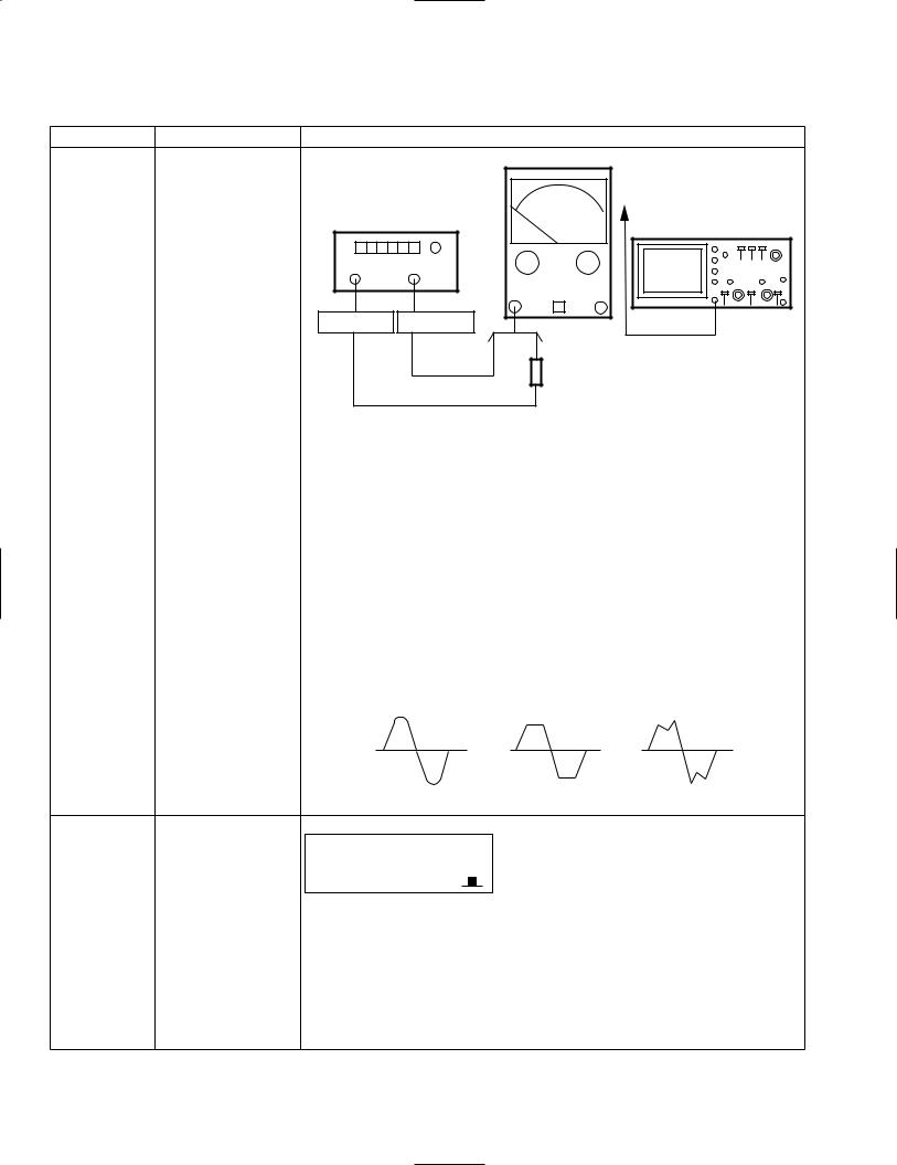
ITEM |
ADJUSTMENT POINT |
|
PROCEDURE |
300mV range |
VR102 |
|
Main unit |
|
|
|
REAR PANEL |
|
|
|
OUT PUT |
|
Oscillator or calibrator |
Oscilloscope |
|
|
|
|
|
|
OUT |
OUT |
|
Oscillator Calibrator
50Ω oscillator
(Unless otherwise specified, the above connection should be used as to the following items.)
CH1/2 SWITCH |
: 300mV |
(VT-185) |
|||
|
0.3V |
(VT-186/VT-187) |
|||
CH2 SWITCH |
: 300mV |
(VT-185) |
|||
|
0.3V |
(VT-186/VT-187) |
|||
CH2 SELECTOR |
: OFF |
|
|
|
|
|
|
|
|
||
|
|
|
|
||
|
|
|
|
|
|
1)Input 1 kHz (or 400 Hz), 300 mVrms sine wave, and set the pointer to 3.0 of the 0-3 scale. Check that the variable range is less than 98% and more than 102% with respect to 3.0 (full-scale).
2)Waveforms shown on the oscilloscope shall not be deformed.
OK |
NG |
NG |
1V range |
VR101 |
CH1/2 SWITCH |
: 1V |
CH2 SWITCH |
: 1V |
CH2 SELECTOR |
: OFF |
1)Input 1kHz (or 400 Hz), 1 Vrms sine wave, and set the pointer to 10.0 V of the 0- 10 scale. Check that the variable range is less than 98% and more than 102% with respect to 10.0 (full-scale).
2)Check that the operating, when CH2 SELECTOR is switched ON (  ) .
) .
3)Waveforms shown on the oscilloscope shall not be deformed.
8
|
|
|
|
|
|
|
|
|
|
VT-185/VT-186/VT-187 |
||||
|
|
|
|
|
ADJUSTMENT |
|
|
|||||||
|
|
|
|
|
|
|
|
|
|
|
|
|
|
|
ITEM |
ADJUSTMENT POINT |
|
|
|
|
|
|
|
|
|
|
PROCEDURE |
|
|
|
|
|
|
|
|
|
|
|
|
|
|
|
|
|
100 kHz |
TC101 |
|
|
|
|
|
|
|
|
|
|
|
|
|
frequency |
|
|
CH1/2 SWITCH |
: 1V |
|
|
|
|
||||||
characteristics |
|
|
CH2 SWITCH |
: 1V |
|
|
|
|||||||
|
|
|
CH2 SELECTOR |
: OFF |
|
|
|
|
|
|
|
|||
|
|
|
|
|
|
|
|
|
|
|
||||
|
|
|
|
|
|
|
|
|
|
|
|
|
|
|
|
|
1) |
Input a 1kHz (or 400 Hz), 1 Vrms sine wave, and adjust the oscillator output so |
|
||||||||||
|
|
|
|
that the pointer of the set points at 9.0. |
|
|
||||||||
|
|
2) |
Adjust the TC so that the pointer points at 9.0 when the frequency is changed to |
|
||||||||||
|
|
|
|
100 kHz while the oscillator output remains unchanged. |
|
|
||||||||
|
|
|
|
|
|
|
|
|
|
|
|
|
Scale 9 |
|
|
|
|
|
|
0 |
|
|
|
|
|
|
|
|
|
|
|
|
|
|
|
|
|
|
|
|
|
|
||
|
|
|
|
|
10 |
|
||||||||
|
|
|
|
|
Scale 0-10 |
|
||||||||
|
|
|
|
|
|
|
||||||||
|
|
|
|
|
|
3 |
|
|
||||||
|
|
|
|
|
|
|
|
|
|
|
|
|
Scale 0-3 |
|
|
|
|
|
|
|
|
|
|
|
|
|
|
|
|
|
|
|
|
|
|
|
|
|
|
|
|
|
|
|
9
 Loading...