


X838 |
CASSETTE RECEIVER |
INSTRUCTION MANUAL |
B64-2185-00 (EV)

English
Contents
Contents...................................... |
2 |
Safety precautions...................... |
3 |
About Cassette tape................... |
5 |
About RDS .................................. |
5 |
General features ......................... |
6 |
Power
Selecting the Source
Volume
Attenuator
Loudness
System Q
Audio Control
Speaker Setting
Display Mode Switching
Switching Full Screen Display
Switching the Standby Display
Switching Upper and Lower Part Display
Auxiliary Input Display Setting
Theft Deterrent Faceplate
TEL Mute
Tuner features........................... |
13 |
Tuning |
|
Direct Access Tuning |
|
Station Preset Memory |
|
Auto Memory Entry |
|
Preset Tuning |
|
SNPP (Station Name Preset Play) |
|
RDS features............................. |
15 |
PTY (Program Type) |
|
Program Type preset |
|
Changing Language for PTY Function
Traffic Information |
|
Radio Text Scroll |
|
Cassette player features |
...........18 |
Playing Cassette Tapes
Fast Forwarding and Rewinding Dolby B NR
Selecting the Tape type
DPSS (Direct Program Search System) Blank Skip
Music Repeat
External disc control features..21
Playing External Disc |
|
Fast Forwarding and Reversing |
|
Track Search |
|
Album Search |
|
Direct Track Search |
|
Direct Album Search |
|
Track/Album Repeat |
|
Track Scan |
|
Random Play |
|
Magazine Random Play |
|
Disc Naming (DNPS) |
|
Text/Title Scroll |
|
DNPP (Disc Name Preset Play) |
|
Menu system............................. |
25 |
Menu System |
|
Security Code |
|
Touch Sensor Tone |
|
Manual Clock Adjustment |
|
Date Adjustment |
|
Date Mode |
|
Synchronize Clock |
|
DSI (Disabled System Indicator) |
|
Selectable Illumination |
|
Font Color Select |
|
Dimmer |
|
System Q |
|
Built-in Amp Mute Setting |
|
B.M.S. (Bass Management System) |
|
B.M.S. Frequency Offset |
|
News Bulletin with Timeout Setting |
|
Local Seek |
|
Tuning Mode |
|
Auto Memory Entry |
|
AF (Alternative Frequency) |
|
Restricting RDS Region |
|
Auto TP Seek |
|
Monaural Reception |
|
Text Scroll |
|
Power OFF Timer |
|
Basic Operations of remote...... |
32 |
Loading and Replacing the battery |
|
Basic operations |
|
In Tuner source |
|
In Cassette tape source |
|
In Disc source |
|
Accessories............................... |
34 |
Installation Procedure .............. |
34 |
Connecting Wires to Terminals... |
35 |
Installation ................................ |
36 |
Troubleshooting Guide ............. |
38 |
Specifications ........................... |
42 |
— 2 —
Safety precautions
2WARNING |
2CAUTION |
To prevent injury and/or fire, take the following precautions:
•Insert the unit all the way until it is fully locked in place. Otherwise it may fly out of place during collisions and other jolts.
•When extending the ignition, battery, or ground wires, make sure to use automotivegrade wires or other wires with a 0.75mm2 (AWG18) or more to prevent wire deterioration and damage to the wire coating.
•To prevent short circuits, never put or leave any metallic objects (e.g., coins or metal tools) inside the unit.
•If the unit starts to emit smoke or strange smells, turn off the power immediately and consult your Kenwood dealer.
•Make sure not to get your fingers caught between the faceplate and the unit.
•Be careful not to drop the unit or subject it to strong shock.
The unit may break or crack because it contains glass parts.
To prevent damage to the machine, take the following precautions:
•Make sure to ground the unit to a negative 12V DC power supply.
•Do not open the top or bottom covers of the unit.
•Do not install the unit in a spot exposed to direct sunlight or excessive heat or humidity. Also avoid places with too much dust or the possibility of water splashing.
•Do not subject the faceplate to excessive shock, as it is a piece of precision equipment.
•When replacing a fuse, only use a new one with the prescribed rating. Using a fuse with the wrong rating may cause your unit to malfunction.
•To prevent short circuits when replacing a fuse, first disconnect the wiring harness.
•Do not place any object between the faceplate and the unit.
•During installation, do not use any screws except for the ones provided. The use of improper screws might result in damage to the main unit.
•Do not apply excessive force to the moving faceplate. Doing so will cause damage or malfunction.
•Do not apply excessive force to the open faceplate or place objects on it. Doing so will cause damage or breakdown.
— 3 —
IMPORTANT INFORMATION
About the disc changer/CD player to be connected:
To connect a disc changer having the "O-N" switch to this unit, set the "O-N" switch to "N". When you connect a model with no "O-N" switch, the converter cord CA-DS100 available as an option may be required. For details, consult your Kenwood dealer.
A disc changer doesn't work when it is connected without using these options.
If a model with no "O-N" switch is connected, some unavailable functions and information that cannot be displayed are generated. Note that none of the KDC-C100, KDC-C302, C205, C705, and non-Kenwood CD changers can be connected.
You can damage both your unit and the CD changer if you connect them incorrectly.
Manufactured under license from Dolby Laboratories.
“Dolby” and the double-D symbol are trademarks of Dolby Laboratories.
English
Safety precautions
NOTE
•If you experience problems during installation, consult your Kenwood dealer.
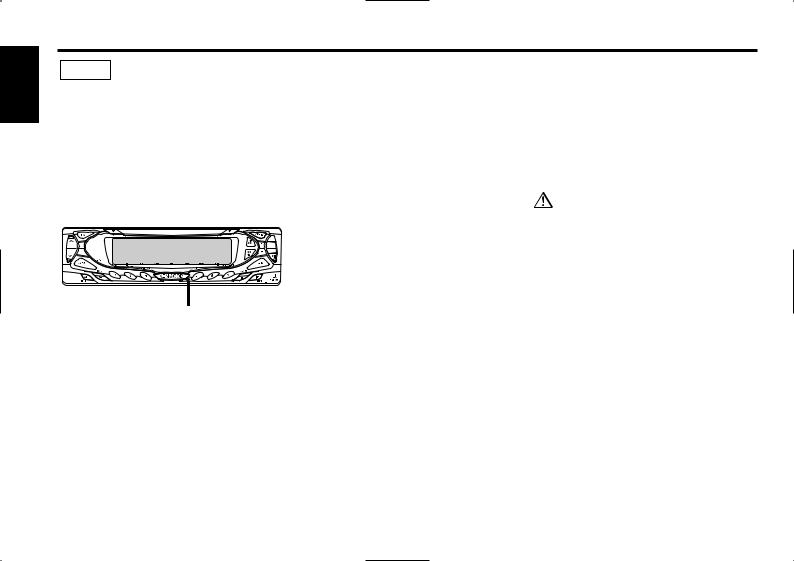
•If the unit fails to operate properly, press the Reset button. The unit returns to factory settings when the Reset button is pressed. If the unit still fails to operate properly after the Reset button has been pressed, contact your local KENWOOD dealer for assistance.
•Press the reset button if the Disc auto changer fails to operate correctly. Normal operation should be restored.
Reset button
•We strongly recommend the use of the Code Security function (see p.26) to prevent theft.
•The illustrations of the display and the panel appearing in this manual are examples used to explain more clearly how the controls are used. Therefore, what appears on the display in the illustrations may differ from what appears on the display on the actual equipment, and some of the illustrations on the display may represent something impossible in actual operation.
Cleaning the Faceplate Terminals
If the terminals on the unit or faceplate get dirty, wipe them with a dry, soft cloth.
Cleaning the Unit
If the faceplate of this unit is stained, wipe it with a dry soft cloth such as a silicon cloth.
If the faceplate is stained badly, wipe the stain off with a cloth moistened with neutral cleaner, then wipe neutral detergent off.
Applying spray cleaner directly to the unit may affect its mechanical parts. Wiping the faceplate with a hard cloth or using a volatile liquid such as thinner or alcohol may scratch the surface or erases characters.
— 4 —

About Cassette tape |
About RDS |
Cleaning the tape head
When there’s noise or the sound quality is bad during tape play the tape head maybe dirty, clean the tape head.
About Cassette tape
•If the tape is slack tighten it.
•If the cassette tape label is peeling off glue it on again.
•Don’t use deformed cassette tape.
•Don’t place cassette tape on the dashboard etc. where the temperature is high.
•Don’t use cassette tape that’s 100 minutes long or longer.
RDS (Radio Data System)
When listening to an RDS station, the program service name of the station is displayed, advising you quickly which station is being received.
RDS (Radio Data System) stations also transmit frequency data for the same station. When you are making long trips, this function automatically alternative switches to the particular frequency with the best reception for the particular network of stations that you want to listen to. The data is automatically stored, allowing you to switch quickly to another RDS stations, broadcasting the same program, that has better reception. These include stations stored in the station preset memory that you often listen to.
Enhanced Other Network
Stations that offer <Enhanced Other Network> also transmit information about other RDS stations that have traffic information. When you are tuned to a station that is not transmitting traffic information, but another RDS station starts transmitting a traffic bulletin, the tuner automatically switches to the other station for the duration of the bulletin.
Alarm
When an emergency transmission (announcing disasters, etc.) is sent, all current functions are interrupted to allow the warning to be received.
— 5 —

English
General features
|
Release button |
u S.A |
¢ FM |
d
ATT/ |
|
4 AM |
LOUD |
|
|
SRC |
Q/ |
DISP |
|
AUD |
|
Power
Turning ON the Power
Press the [SRC] button.
When the power is ON, the <Security Code> (page 26) is displayed as "CODE ON" or "CODE OFF".
Turning OFF the Power
Press the [SRC] button for at least 1 second.
Selecting the Source
Press the [SRC] button. |
|
Source required |
Display |
|
|
|
|
|
|
|
Tuner |
"TUNER" |
|
|
|
|
|
|
|
Tape |
"TAPE" |
|
|
|
|
|
|
|
External disc |
"CD"/"DISC" |
|
|
|
|
|
|
|
Auxiliary input |
"AUX" |
|
|
|
|
|
|
|
Standby (Illumination only mode) |
"ALL OFF" |
|
|
|
|
|
|
|
• For Auxiliary input one of the below optional accessories is |
|
|
|
|
|
|
|
|
necessary. |
|
|
|
|
|
|
|
|
- KCA-S210A |
|
|
|
|
|
|
|
|
- CA-C1AX |
|
IN |
P/S |
ATT |
ST |
LOUD |
RDS |
TI |
- CD changer with an Auxiliary input function installed. |
|
|
|
|
|
|
|
|
||
|
|
ATT indicator |
|
LOUD indicator |
|
|
• This unit automatically turns full power OFF after 20 minutes |
|
|
|
|
|
|
lapses in Standby mode in order to save the vehicles battery. |
|||
|
|
|
|
|
|
|
The time until full power OFF can be set in <Power OFF Timer> |
|
|
|
|
|
|
|
|
(page 31). |
|
— 6 —
Volume
Increasing Volume
Press the [u] button.
Decreasing Volume
Press the [d] button.
Attenuator
Turning the volume down quickly.
Press the [ATT] button.
Each time the button is pressed the Attenuator turns ON or OFF. When it’s ON, the "ATT" indicator blinks.
Loudness
Compensating for low and high tones during low volume.
Press the [LOUD] button for at least 1 second.
Each time the button is pressed for at least 1 second the Loudness turns ON or OFF.
When it’s ON, "LOUD" indicator is ON.
System Q
You can recall the best sound setting preset for different types of the music.
1Select the source to set
Press the [SRC] button.
2Select the Sound type
Press the [Q] button.
Each time the button is pressed the sound setting switches.
Sound setting |
Display |
Flat |
"FLAT" |
User memory |
"User Preset" |
Rock |
"ROCK" |
Pops |
"POPS" |
Easy |
"EASY" |
Top 40 |
"TOP 40" |
Jazz |
"JAZZ" |
•User memory: The values set on the <Audio control> (page 8).
•Each setting value is changed with the <Speaker setting> (page 8).
First, select the speaker type with the Speaker setting.
— 7 —
English
General features
Audio Control
1Select the source for adjustment
Press the [SRC] button.
2Enter Audio Control mode
Press the [AUD] button for at least 1 second.
3Select the Audio item for adjustment
Press the [FM] or [AM] button.
Each time the button is pressed the items that can be adjusted switch as shown below.
4Adjust the Audio item
Press the [4] or [¢] button.
Adjustment Item |
Display |
Range |
Bass Center Frequency |
"Bass FRQ" |
60/70/80/100 or 150 Hz |
Bass level |
"Bass" |
–8 — +8 |
Bass Q Factor |
"Bass Q" |
1.00/1.25/1.50/2.00 |
Bass Extend |
"Bass EXT" |
ON/OFF |
Middle Center |
"MID FRQ" |
0.5/1.0/1.5/2.0 kHz |
Frequency |
|
|
Middle level |
"MID" |
–8 — +8 |
Middle Q Factor |
"Middle Q" |
1.0/2.0 |
Treble Center |
"TRE FRQ" |
10.0/12.5/15.0/17.5 kHz |
Frequency |
|
|
Treble level |
"TRE" |
–8 — +8 |
Balance |
"Balance" |
Left 15 — Right 15 |
Fader |
"Fader" |
Rear 15 — Front 15 |
Volume offset |
"Volume Offset" –8 — ±0 |
|
•According to the Bass Q Factor setting value, the frequencies that can be set in Bass Center Frequency change as shown below.
Bass Q Factor |
Bass Center Frequency |
1.00/1.25/1.50 |
60/70/80/100 |
2.00 |
60/70/80/150 |
•When the Bass Extend is set to ON, low frequency response is extended by 20%.
•Volume offset: Each source's volume can be set as a difference
from the basic volume.
5Exit Audio Control mode
Press the [AUD] button.
Speaker Setting
Fine-tuning so that the System Q value is optimal when setting the speaker type.
1Enter Standby
Press the [SRC] button.
Select the "ALL OFF" display.
2Enter Speaker Setting mode
Press the [Q] button.
"Speaker Setting" is displayed.
3Select the Speaker type
Press the [4] or [¢] button.
Each time the button is pressed the setting switches as shown below.
Speaker type |
Display |
|
OFF |
|
"OFF" |
For 5 |
& 4 in. speaker |
"5/4 inch" |
For 6 |
& 6x9 in. speaker |
"6*9/6 inch" |
|
|
|
For the OEM speaker |
"O.E.M." |
|
4Exit Speaker Setting mode
Press the [Q] button.
— 8 —
Display Mode Switching
Switching the display mode.
Press the [DISP] button.
Each time the button is pressed the Display mode switches as shown below.
Display mode |
Display |
Upper and lower division display type |
"Display Type A" |
Type that mainly uses the display upper part |
"Display Type B" |
Full screen display type |
"Display Type C" |
•The display of each part can be changed.
-Switching Upper and Lower Part Display: (page 10)
-Switching Full Screen Display: (page 9)
•"Display Type C" can’t be selected in "ALL OFF".
Switching Full Screen Display
Switching the Full screen display.
Press the [S.A] button.
Each time the button is pressed the display switches as shown below.
Information
Demonstration
Spectrum Analyzer 1
Spectrum Analyzer 2
Spectrum Analyzer 3
Spectrum Analyzer 4
Spectrum Analyzer 5
Full Screen display can be selected when "Display Type C" is selected in <Display Mode Switching> (page 9).
Switching the Standby Display
Switching the information displayed in Standby.
1Enter Standby
Press the [SRC] button.
Select the "ALL OFF" display.
2Switch the display
Press the [S.A] button.
Each time the button is pressed the display switches as shown below.
Information |
Display |
Demonstration |
|
Date & Clock |
|
Standby display |
"ALL OFF" |
•Demonstration can be selected when "Display Type A" is selected in <Display Mode Switching> (page 9).
•Only "Display Type A" and "Display Type B" can be selected in "ALL OFF".
— 9 —

English
General features
Switching Upper and Lower Part Display
Switching the upper and lower part display.
1Select the Display Type
Press the [DISP] button.
2Enter Display Control mode
Press the [S.A] button.
"Display Control Mode On" is displayed.
3Switch the Upper part display
Press the [FM] or [AM] button.
Switch the Lower part display
Press the [4] or [¢] button.
Each time the button is pressed the display switches.
The Reference for the display content is after this operation's explanation.
4Exit Display Control mode
Press the [S.A] button.
•The same information can't be displayed on the Upper part display and lower part display.
•The Upper part display and Lower part display switching can be selected when "Display Type A" is selected in <Display Mode switching> (page 9).
•When "Display Type B" is selected the Lower part display content is clock ON or OFF.
The Frequency is displayed during Program Service name reception
Press the [DISP] button for at least 1 second.
The frequency for the RDS station will be displayed for 5 seconds instead of the Program Service name.
Lower Part Display |
|
|
|
Information |
Display |
|
Spectrum Analyzer & Graphic |
"S/ANA+GRAPHIC" |
|
Spectrum Analyzer & Clock |
"S/ANA+CLOCK" |
|
Spectrum Analyzer |
"S/ANA" |
|
Radio text |
"R-TEXT" |
|
Date |
"DATE" |
|
Clock & Graphic |
"CLOCK+GRAPHIC" |
In Tape source |
|
|
Upper Part Display |
|
|
|
Information |
Display |
|
Play side & Tape counter |
"SIDE+COUNTER" |
|
Play side & Tape running |
"SIDE+RUNNING" |
|
Play side |
"SIDE" |
Lower Part Display |
|
|
|
|
|
|
|
|
|
Information |
Display |
|
|
|
|
|
|
|
Spectrum Analyzer & Graphic |
"S/ANA+GRAPHIC" |
In Tuner source |
|
|
|
|
|
|||
|
|
|
|
|
Spectrum Analyzer & Clock |
"S/ANA+CLOCK" |
||
Upper Part Display |
|
|
|
|
|
Spectrum Analyzer |
"S/ANA" |
|
|
|
|
|
|
Date |
"DATE" |
||
|
Information |
Display |
|
|
|
|
||
|
|
|
|
|
Clock & Graphic |
"CLOCK+GRAPHIC" |
||
|
Program Service name or Frequency |
"BAND+ch+PS" |
|
|
|
|
||
|
|
|
|
|
|
|
||
|
Radio text |
"R-TEXT" |
|
|
|
|
|
|
|
|
|
— |
|
10 — |
|
||
|
|
|
|
|
||||
In CD/ External disc source |
|
|
Upper Part Display |
|
|
|
Information |
Display |
|
Track Time |
"P-Time" |
|
Disc name |
"DNPS" |
|
Disc title |
"DISC-TITLE" |
|
Track title |
"TRACK-TITLE" |
Lower Part Display |
|
|
|
Information |
Display |
|
Spectrum Analyzer &Graphic |
"S/ANA+GRAPHIC" |
|
Spectrum Analyzer & Clock |
"S/ANA+CLOCK" |
|
Spectrum Analyzer |
"S/ANA" |
|
Track Title |
"TRACK-TITLE" |
|
Disc Title |
"DISC-TITLE" |
|
Disc name (CD player / CD changer) |
"DNPS" |
|
Date |
"DATE" |
|
Clock & Graphic |
"CLOCK+GRAPHIC" |
In Auxiliary input source |
|
|
Lower Part Display |
|
|
|
Information |
Display |
|
Spectrum Analyzer & Graphic |
"S/ANA+GRAPHIC" |
|
Spectrum Analyzer & Clock |
"S/ANA+CLOCK" |
|
Spectrum Analyzer |
"S/ANA" |
|
Date |
"DATE" |
|
Clock & Graphic |
"CLOCK+GRAPHIC" |
The Auxiliary input name is always displayed on the Upper part display.
Auxiliary Input Display Setting
Selecting the display when this device is switched to Auxiliary input source.
1Select Auxiliary input source
Press the [SRC] button.
Select the "AUX" display.
2Enter Auxiliary input display setting mode
Press the [DISP] button for at least 2 seconds.
The presently selected AUX Name is blinks.
3Select the Auxiliary input display
Press the [4] or [¢] button.
Each time the button is pressed it switches through the below displays.
•"AUX"
•"TV"
•"VCP"
•"GAME"
•"PORTABLE"
•"DVD"
4Exit Auxiliary input display setting mode
Press the [DISP] button.
When operation stops for 10 seconds, the name at that time is selected, and Auxiliary input display setting mode closes.
— 11 —
English
General features
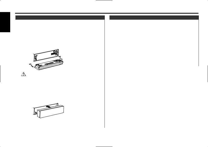
Theft Deterrent Faceplate
The faceplate of the unit can be detached and taken with you, helping to deter theft.
Removing the Faceplate
1Press the Release button.
Drop open the faceplate.
2Drawing the faceplate to left side pull it to the front and remove it.
• The faceplate is a precision piece of equipment and can be damaged by shocks or jolts. For that reason, keep the faceplate in its special storage case while detached.
•Do not expose the faceplate or its storage case to direct sunlight or excessive heat or humidity. Also avoid places with too much dust or the possibility of water splashing.
Reattaching the Faceplate
1Align the shaft on the unit with the depression on the faceplate.
TEL Mute
The audio system automatically mutes when a call comes in.
When a call comes in
"CALL" is displayed.
The audio system pauses.
Listening to the audio during a call
Press the [SRC] button.
The "CALL" display disappears and the audio system comes back ON.
When the call ends
Hang up the phone.
The "CALL" display disappears and the audio system comes back ON.
2Push the faceplate in until it clicks.
The faceplate is locked in place, allowing you to use the unit.
— 12 —
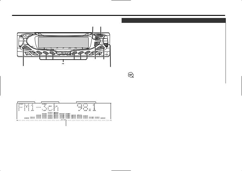
Tuner features
Tuning
¢ FM
4 AM
#1 #6
SRC |
MENU |
|
Selecting the station.
1Select tuner source
Press the [SRC] button.
Select the "TUNER" display.
2Select the band
Press the [FM] or [AM] button.
Each time the [FM] button is pressed it switches between the FM1, FM2, and FM3 bands.
3Tune up or down band
Press the [4] or [¢] button.
•The sound will be temporarily muted while the faceplate is moving.
•During reception of stereo stations the "ST" indicator is ON.
Band display |
|
Preset station number |
Frequency display |
|
||
IN |
P/S |
ATT |
ST |
LOUD |
RDS |
TI |
ST indicator
— 13 —

English
Tuner features
Direct Access Tuning (Function of remote)
Entering the frequency and tuning.
1Select the band
Press the [FM] or [AM] button.
2Enter Direct Access Tuning mode
Press the [DIRECT] button on the remote.
"– – – –" is displayed.
3Enter the frequency
Press the number buttons on the remote.
Example:
Desired frequency |
Press button |
92.1 MHz (FM) |
[#0], [#9], [#2], [#1] |
810 kHz (AM) |
[#0], [#8], [#1], [#0] |
Canceling Direct Access Tuning
Press the [DIRECT] button on the remote.
Station Preset Memory
Putting the station in the memory.
1Select the band
Press the [FM] or [AM] button.
2Select the frequency to put in the memory
Press the [4] or [¢] button.
3Put the frequency in the memory
Press the [#1] — [#6] button for at least 2 seconds.
The preset number display blinks 1 time.
On each band, 1 station can be put in the memory on each [#1]
— [#6] button.
Auto Memory Entry
Putting a station with good reception in the memory automatically.
1Select the band for Auto Memory Entry
Press the [FM] or [AM] button.
2Enter Menu mode
Press the [MENU] button for at least 1 second.
"MENU" is displayed.
3Select the Auto Memory Entry mode
Press the [FM] or [AM] button.
Select the "A-Memory" display.
4Open Auto Memory Entry
Press the [4] or [¢] button for at least 2 seconds.
When 6 stations that can be received are put in the memory Auto Memory Entry closes.
•When the <AF Function> (page 30) is ON, only RDS stations are put in the memory.
•When Auto Memory Entry is done in the FM2 band, the RDS stations preset in the FM1 band aren't put in the memory. Likewise, when it is done in the FM3 band, RDS stations preset in FM1 or FM2 aren't put in the memory.
Preset Tuning
Calling up the stations in the memory.
1Select the band
Press the [FM] or [AM] button.
2Call up the station
Press the [#1] — [#6] button.
— 14 —
 Loading...