


RC-D710
CONTROL PANEL
INSTRUCTION MANUAL
PANNEAU DE CONTROLE
MODE D’EMPLOI
PANEL DE CONTROL
MANUAL DE INSTRUCCIONES
Only basic operations are explained in this instruction manual. For a detailed explanation on the operations, refer to the PDF file supplied on the CD-ROM.
Seules les fonctions de base sont expliquées dans ce mode d’emploi. Pour le détail sur les autres opérations, reportez-vous au fichier PDF à votre disposition sur le CD-ROM.
En este manual de instrucciones solamente se explican las operaciones básicas. Si desea obtener una descripción detallada de las operaciones, consulte el archivo PDF correspondiente incluido en el CD-ROM.
細説明は付属CD-ROM PDF
© B62 2003 00 (W)
09 08 07 06 05 04 03 02 01 00

CONTROL PANEL
RC-D710
INSTRUCTION MANUAL
ENGLISH

Thank You
We are grateful you decided to purchase this RC-D710.
Features
RC-D710 has the following main features:
•Has a built-in TNC which conforms to the AX.25protocol. With a portable computer, allows you to enjoy Packet operation quite easily.
•Includes a program for dealing with data formats supported by Automatic Packet/ Position Reporting System (APRS®).
•<RC-D710 + TM-V71>
When the RC-D710 is connected to the TM-V71A/E, the available functions are the same as the TM-D710A/E.
•<RC-D710 + PG-5J>
When the RC-D710 is connected to the DATA terminal of a transceiver via the PG-5J (option), with the RC-D710 built-in TNC, you can use PACKET and APRS mode (Stand Alone mode).
Notices to the User
One or more of the following statements may be applicable:
FCC WARNING
This equipment generates or uses radio frequency energy. Changes or modifications to this equipment may cause harmful interference unless the modifications are expressly approved in the instruction manual. The user could lose the authority to operate this equipment if an unauthorized change or modification is made.
INFORMATION TO THE DIGITAL DEVICE USER REQUIRED BY THE FCC
This equipment has been tested and found to comply with the limits for a Class B digital device, pursuant to Part 15 of the FCC Rules. These limits are designed to provide reasonable protection against harmful interference in a residential installation.
This equipment generates, uses and can generate radio frequency energy and, if not installed and used in accordance with the instructions, may cause harmful interference to radio communications. However, there is no guarantee that the interference will not occur in a particular installation. If this equipment does cause harmful interference to radio or television reception, which can be determined by turning the equipment off and on, the user is encouraged to try to correct the interference by one or more of the following measures:
•Reorient or relocate the receiving antenna.
•Increase the separation between the equipment and receiver.
•Connect the equipment to an outlet on a circuit different from that to which the receiver is connected.
•Consult the dealer for technical assistance.
Information on Disposal of Old Electrical and Electronic Equipment (applicable for EU
countries that have adopted separate waste collection systems)
Products with the symbol (crossed-out wheeled bin) cannot be disposed as household waste.
Old electrical and electronic equipment should be recycled at a facility capable of handling these items and their waste byproducts. Contact your local authority for details in locating a recycle facility nearest to you. Proper recycling and waste disposal will help conserve resources whilst preventing detrimental effects on our health and the environment.

Precautions
Observe the following precautions to prevent fire, personal injury, and RC-D710/ transceiver damage.
•When operating mobile, do not attempt to configure the RC-D710 while driving; it is too dangerous.
•Do not expose the RC-D710 to long periods of direct sunlight, nor place it near heating appliances.
•Do not place the RC-D710 in excessively dusty, humid, or wet areas, nor on unstable surfaces.
•If an abnormal odor or smoke is detected coming from the RC-D710 or transceiver, switch the RC-D710/ transceiver power off immediately, and contact a Kenwood service station or your dealer.
•Do not use options not specified by Kenwood.
Writing Conventions Followed in this Manual
The writing conventions described below have been followed to simplify instructions and avoid unnecessary repetition.
Instruction |
Action |
|
|
|
|
Press [KEY]. |
Momentarily press KEY. |
|
|
|
|
Press [KEY] (1s). |
Press and hold KEY for 1 second or longer. |
|
|
|
|
Press [KEY1], [KEY2]. |
Press KEY1 momentarily, release KEY1, then press |
|
KEY2. |
||
|
||
|
|
|
Press [F], [KEY]. |
Press the F key to enter Function mode, then press |
|
KEY to access its secondary function. |
||
|
||
|
|
|
Press [KEY] + Power ON. |
With the transceiver power OFF, press and hold |
|
KEY while turning the transceiver power ON. |
||
|
||
|
|
ii

CONTENTS |
|
PREPARATION................................................................................................ |
1 |
Supplied Accessories........................................................................ |
1 |
Installation........................................................................................... |
2 |
Connection TO PC................................................................................ |
3 |
Connection TO TM-V71......................................................................... |
3 |
Connection TO PG-5J........................................................................... |
4 |
GETTING ACQUAINTED.................................................................................. |
6 |
OPERATION Panel (FRONT) <RC-D710 + TM-V71>.............................. |
6 |
OPERATION Panel (REAR & LEFT)........................................................ |
9 |
Display <RC-D710 + TM-V71>.............................................................. |
10 |
OPERATION Panel (FRONT) <RC-D710 + PG-5J>.............................. |
12 |
BASIC OPERATIONS (RC-D710 + TM-V71).................................................. |
14 |
Switching THE Power ON/ OFF........................................................ |
14 |
Adjusting the Volume...................................................................... |
14 |
ADJUSTING THE SQUELCH.................................................................... |
14 |
Selecting a BAND................................................................................ |
15 |
SELECTING Dual band mode/ single band MODE....................... |
16 |
SELECTING A frequency band........................................................ |
17 |
Selecting an Operating mode...................................................... |
18 |
Transmitting........................................................................................ |
19 |
MENU MODE.................................................................................................. |
20 |
Menu Access........................................................................................ |
20 |
Menu Configuration......................................................................... |
21 |
Character Entry............................................................................... |
32 |
MAINTENANCE.............................................................................................. |
34 |
GENERAL INFORMATION....................................................................... |
34 |
SERVICE................................................................................................... |
34 |
SERVICE NOTE........................................................................................ |
34 |
CLEANING................................................................................................ |
34 |
SPECIFICATIONS.......................................................................................... |
35 |
iii

For a detailed explanation on the operation, refer to the PDF file supplied on the CDROM.
•Titles denoted with <RC-D710 + TM-V71> are operation explanations only for when the RC-D710 is connected to the TM-V71(A/E). Titles without this indication include operation explanations for when connecting the RC-D710 to the PG-5J.
•In the explanations, the term "transceiver" is generally referring to the RC-D710 + TM-V71(A/E).
Operation |
File name |
|
|
|
|
CONTENTS |
00-CONTENTS-E.pdf |
|
|
|
|
OPERATING THROUGH REPEATERS |
01-REPEATER-E.pdf |
|
<RC-D710 + TM-V71> |
||
|
||
|
|
|
MEMORY CHANNELS <RC-D710 + TM-V71> |
02-MEMORY CHANNEL-E.pdf |
|
|
|
|
PROGRAMMABLE MEMORY (PM) |
03-PM CHANNEL-E.pdf |
|
|
|
|
SCAN <RC-D710 + TM-V71> |
04-SCAN-E.pdf |
|
|
|
|
CONTINUOUS TONE CODED SQUELCH SYSTEM |
05-CTCSS-E.pdf |
|
(CTCSS) <RC-D710 + TM-V71> |
||
|
||
|
|
|
DIGITAL CODED SQUELCH (DCS) |
06-DCS-E.pdf |
|
<RC-D710 + TM-V71> |
||
|
||
|
|
|
DUAL TONE MULTI-FREQUENCY (DTMF) |
07-DTMF-E.pdf |
|
<RC-D710 + TM-V71> |
||
|
||
EchoLink® <RC-D710 + TM-V71> |
08-EchoLink-E.pdf |
|
OTHER OPERATIONS |
09-OTHER OPERATIONS-E.pdf |
|
|
|
|
PACKET OPERATION |
10-PACKET-E.pdf |
|
|
|
|
APRS® |
11-APRS-E.pdf |
|
RESET |
12-RESET-E.pdf |
|
|
|
|
VGS-1 (OPTIONAL) OPERATION |
13-VGS-E.pdf |
|
<RC-D710 + TM-V71> |
||
|
||
|
|
|
CROSS-BAND/ LOCKED-BAND OPERATION |
14-CROSS BAND (K TYPE)-E.pdf |
|
<WITH TM-V71(A) K TYPE ONLY> |
||
|
||
|
|
|
WIRELESS OPERATION |
15-WIRELESS (K TYPE)-E.pdf |
|
<WITH TM-V71(A) K TYPE ONLY> |
||
|
||
|
|
|
WEATHER ALERT |
16-WEATHER ALERT (K TYPE)-E.pdf |
|
<WITH TM-V71(A) K TYPE ONLY> |
||
|
||
|
|
|
SKY COMMAND |
17-SKY COMMAND (K TYPE)-E.pdf |
|
<WITH TM-V71(A) K TYPE ONLY> |
||
|
Note: Operations file is available in PDF file format. To read the file, you must use Adobe® Reader®.
iv

PREPARATION
Supplied Accessories
|
Item |
Part Number |
Quantity |
|
|
|
|
|
|
Modular plug cable (for PANEL jack) |
E30-7639-XX |
1 |
||
|
|
|
|
|
Line filter |
|
|
L79-1417-XX |
2 |
|
|
|
|
|
Cable with a 2.5 mm (1/10") 3-conductor plug (for |
E30-3400-XX |
1 |
||
GPS jack) |
|
|
||
|
|
|
|
|
|
|
|
|
|
Base stand |
|
|
J09-0409-XX |
1 |
|
|
|
|
|
• Sheet |
|
|
G11-4438-XX |
1 |
|
|
|
|
|
Panel holder |
|
|
J29-0663-XX |
1 |
|
|
|
|
|
• Cushion |
|
|
G13-2233-XX |
1 |
|
|
|
|
|
Panel bracket |
|
|
J29-0707-XX |
1 |
|
|
|
|
|
• Sheet |
|
|
G11-4228-XX |
1 |
|
|
|
|
|
Screw set |
|
|
N99-2055-XX |
1 |
|
|
|
|
|
Warranty Card |
|
For USA/ CANADA |
—— |
1 |
|
|
|
|
|
|
For Europe |
—— |
1 |
|
|
|
|||
|
|
|
|
|
|
|
English, French, |
B62-2003-XX |
1 |
|
|
Spanish, Japanese |
||
Instruction manual |
|
|
|
|
|
|
|
|
|
|
Italian, German, Dutch, |
B62-2004-XX |
1 |
|
|
|
|||
|
|
Chinese (traditional) |
||
|
|
|
|
|
|
|
|
|
|
CD-ROM (For a detailed explanation on the |
T93-0134-XX |
1 |
||
operation) |
|
|
||
|
|
|
|
|
|
|
|
|
|
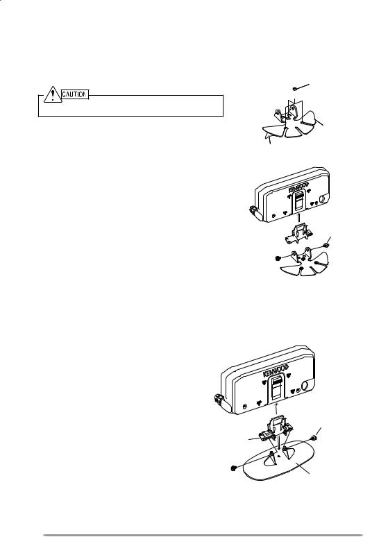
Installation
νMobile Installation
1 Clean and dry the installation location.
Do not install the bracket close to an air bag.
2Remove the release paper from the base of the panel bracket, then secure it in place using the 3 supplied self-tapping screws.
•Allow the panel to set for a while, to ensure it remains fast. Otherwise, vibrations may occur.
•After removing the release paper, it cannot be reused.
3Attach the panel holder to the panel bracket using the 2 supplied SEMS screws.
4Attach the RC-D710 to the panel holder so that it locks in place.
νFixed Station
Tapping screw (4 mm x 12 mm)
 Flat washer
Panel bracket
Adhesive tape
SEMS screw (M4 x 10 mm)
Panel holder 


1Attach the panel holder to the base stand using the 2 supplied SEMS screws.
2Attach the RC-D710 to the panel
holder so that it locks in place.
SEMS screw (M4 x 10 mm)
Panel holder
Base stand
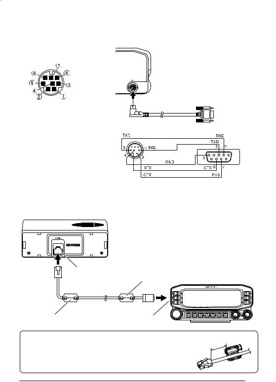
Connection TO PC
Use a PG-5G (option) cable when connecting the RC-D710 to a computer D-SUB terminal.
COM terminal pin
|
NC |
|
NC |
NC |
|
RXD |
TXD |
|
GND |
||
RTS |
||
CTS |
PG-5G (option) |
To PC 9-pin |
|
|
|
D-SUB terminal |
PG-5G pin configuration (cross connection) |
|
CONNECTION TO TM-V71
Connect the RC-D710 to the TM-V71 using the supplied cable.
TM-V71
|
Panel jack |
|
|
|
Line filter |
RC-D710 |
|
|
Modular plug cable |
|
|
Line filter |
Panel jack |
|
|
Installing the Line Filter |
Approx. 3 cm |
||
Install the line filter approximately 3 cm from the |
|||
|
|||
connector. |
|
|
|

Connection TO PG-5J
When using the RC-D710 with a transceiver other than the TM-V71, attach the RC-D710 to the transceiver using the PG-5J (option).
|
To 13.8 |
V DC power supply |
||||
|
or 12 |
V vehicle battery |
||||
DATA terminal |
Black (—) |
|
|
|
Red (+) |
|
|
|
|||||
|
cable |
|
|
|
cable |
|
|
Transceiver |
|
|
|
|
|
|
|
|
|
|
|
|
DATA terminal
Panel jack
PG-5J
Line filter |
DC power cable |
6 pin mini-DIN cable |
|
RC-D710 |
Modular plug cable |
Line filter
Panel jack |
|
|
|
|
|
DATA terminal pin |
No. |
Name |
I/O |
Function |
|
(PG-5J) |
|
|
|
|
TNC data output |
|
|
|
|
|
|
SQC |
NC |
q |
PKD |
O |
2 Vp-p/ 10 kΩ (9600 bps data) |
|
|
|
40 mVp-p/ 10 kΩ (1200 bps data) |
||
|
|
|
|
|
|
PR9 |
PKS |
w |
GND |
— |
GND |
|
|
|
|
||
GND |
PKD |
|
|
|
Data standby control signal output |
e |
PKS |
O |
Open corrector TX : L level / RX : Hi |
||
|
|
|
|
|
impedance |
|
|
r |
PR9 |
I |
TNC data input (9600 bps) |
|
|
350 mVp-p to 600 mVp-p/ 10 kΩ |
|||
|
|
|
|
|
|
|
|
t |
NC |
— |
No connection |
|
|
y |
SQC |
I |
Squelch control signal input |
|
|
SQL Open: H level / Close: L level |
|||
|
|
|
|
|
|
νPower Cable Connection (PG-5J)
Fixed Station
In order to use the PG-5J for fixed station operation, you will need a separate 13.8 V DC power supply that must be purchased separately.
Note: Do not plug the DC power supply into an AC outlet until you make all connections.
Mobile Installation
Be sure to use a 12 V vehicle battery that has sufficient current capacity. If the current to the PG-5J is insufficient, the display may darken during transmission or the transmit output power may drop excessively. Never connect the transceiver to a 24 V battery.
Note: Install the PG-5J Interface Box using the included screw set in a location where it will not interfere with driving.
νReplacing Fuses (PG-5J)
If the fuse blows, determine the cause, then correct the problem. After the problem is resolved, replace the fuse. If newly installed fuses continue to blow, disconnect the power cable and contact your authorized Kenwood dealer or an authorized Kenwood service center for assistance.
Only use fuses of the specified type and rating; otherwise the PG-5J could be damaged.
Fuse
Fuse holder
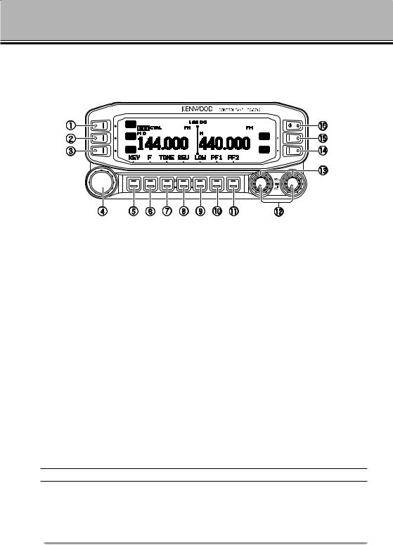
GETTING ACQUAINTED
OPERATION Panel (FRONT) <RC-D710 + TM-V71>
ν IN NORMALMODE
q CALL
Press [CALL] to select the Call channel. Press [CALL] (1s) to start Call scan.
w VFO
Press [VFO] to enter VFO mode , then rotate the Tuning control to select an operating frequency.
Press [VFO] (1s) to start VFO scan.
e MR
Press [MR] to enter Memory Channel mode, then rotate the Tuning control to select a Memory channel.
Press [MR] (1s) to start Memory scan.
rTuning Control
Rotate to select an operating frequency or Memory channel, change the scan direction, etc.
Press the Tuning control to enter MHz mode (while in VFO or Call mode) or to toggle the display between the channel name and frequency (while in Memory Channel mode).
Press Tuning control (1s) to start MHz scan or Group scan.
tKEY
Press [KEY] to turn the APRS key function ON and OFF.
Note: For APRS key functions, refer to the APRS explanation.
yF
Press [F] to enter Function mode.
Press [F] (1s) to turn the transceiver key lock function ON and OFF.

uTONE
Press [TONE] to turn the Tone function ON.
Each time you press [TONE] to toggle the functions as follows: Tone ON >> CTCSS ON >> DCS ON >> OFF.
iREV
Press [REV] to turn the Reverse function ON or OFF.
Press [REV] (1s) to turn the Automatic Simplex Checker ON.
oLOW
Press [LOW] to toggle the transmit output power as follows: High Power (with TM-V71(A/E) K, E types only) –> Middle Power –> Low Power.
!0PF1
Press [PF1] to activate its programmable function.
!1PF2
Press [PF2] to activate its programmable function.
!2BAND SEL (VOL) Control
Rotate the [BAND SEL] control to adjust the speaker volume.
Press the left [BAND SEL] to select the A band. Press the right [BAND SEL] to select the B band.
Press [BAND SEL] (1s) to toggle between single and dual-band mode.
!3SQL Control
Rotate the [SQL] control to adjust the squelch level. Clockwise opens the squelch and counterclockwise tightens the squelch.
!4TNC
Press [TNC] to turn built-in TNC ON and the APRS (or NAVITRA) mode ON. Each time you press [TNC], the mode toggles as follows: APRS (or NAVITRA) mode ON >> PACKET mode ON >> TNC OFF.
•When the built-in TNC turns on, “OPENING TNC” appears on the display.
•When “OPENING TNC” appears on the display, the mode cannot be changed.
!5PM
Press [PM] to enters the PM (Programmable Memory) channel selection mode.
!6
Press  ] to turn the transceiver power ON and OFF.
 Loading...