


INSTRUCTION MANUAL
VHF DIGITAL TRANSCEIVER
NX-248
UHF DIGITAL TRANSCEIVER
NX-348
© B5A-0068-10 (C)

THANK YOU
We are grateful you have chosen KENWOOD for your land mobile radio applications.
NOTICES TO THE USER
Government law prohibits the operation of unlicensed radio transmitters within the territories under government control.
Illegal operation is punishable by fine and/or imprisonment.
Refer service to qualified technicians only.
Safety: It is important that the operator is aware of, and understands, hazards common to the operation of any transceiver.
The AMBE+2TM voice coding Technology embodied in this product is protected by intellectual property rights including patent rights, copyrights and trade secrets of Digital Voice Systems, Inc. This voice coding Technology is licensed solely for use within this Communications Equipment. The user of this Technology is explicitly prohibited from attempting to extract, remove, decompile, reverse engineer, or disassemble the Object Code, or in any other way convert the Object Code into a human-readable form. U.S. Patent Nos. #5,826,222, #5,754,974, #5,701,390, and #5,715,365.
Firmware Copyrights
The title to and ownership of copyrights for firmware embedded in KENWOOD product memories are reserved for JVC KENWOOD Corporation.
i

PRECAUTIONS
•Do not charge the transceiver and battery pack when they are wet.
•Ensure that there are no metallic items located between the transceiver and the battery pack.
•Do not use options not specified by KENWOOD.
•If the die-cast chassis or other transceiver part is damaged, do not touch the damaged parts.
•If a headset or headphone is connected to the transceiver, reduce the transceiver volume. Pay attention to the volume level when turning the squelch off.
•Do not place the microphone cable around your neck while near machinery that may catch the cable.
•Do not place the transceiver on unstable surfaces.
•Ensure that the end of the antenna does not touch your eyes.
•When the transceiver is used for transmission for many hours, the radiator and chassis will become hot. Do not touch these locations when replacing the battery pack.
•Do not immerse the transceiver in water.
•Always switch the transceiver power off before installing optional accessories.
•The charger is the device that disconnects the unit from the AC mains line. The AC plug should be readily accessible.
Turn the transceiver power off in the following locations:
•In explosive atmospheres (inflammable gas, dust particles, metallic powders, grain powders, etc.).
•While taking on fuel or while parked at gasoline service stations.
•Near explosives or blasting sites.
•In aircraft. (Any use of the transceiver must follow the instructions and regulations provided by the airline crew.)
•Where restrictions or warnings are posted regarding the use of radio devices, including but not limited to medical facilities.
•Near persons using pacemakers.
ii

•Do not disassemble or modify the transceiver for any reason.
•Do not place the transceiver on or near airbag equipment while the vehicle is running. When the airbag inflates, the transceiver may be ejected and strike the driver or passengers.
•Do not transmit while touching the antenna terminal or if any metallic parts are exposed from the antenna covering. Transmitting at such a time may result in a high-frequency burn.
•If an abnormal odor or smoke is detected coming from the transceiver, switch the transceiver power off immediately, remove the battery pack from the transceiver, and contact your
KENWOOD dealer.
•Use of the transceiver while you are driving may be against traffic laws. Please check and observe the vehicle regulations in your area.
•Do not expose the transceiver to extremely hot or cold conditions.
•Do not carry the battery pack (or battery case) with metal objects, as they may short the battery terminals.
•When attaching a commercial strap to the transceiver, ensure that the strap is durable. In addition, do not swing the transceiver round by the strap; you may inadvertently strike and injure another person with the transceiver.
•If a commercially available neck strap is used, take care not to let the strap get caught on nearby machine.
•When operating the transceiver in areas where the air is dry, it is easy to build up an electric charge (static electricity). When using an earphone accessory in such conditions, it is possible for the transceiver to send an electric shock through the earphone and to your ear. We recommend you use only a speaker/microphone in these conditions, to avoid electric shocks.
•To dispose of batteries, be sure to comply with the laws and regulations in your country or region.
iii

Information concerning the battery pack:
The battery pack includes flammable objects such as organic solvent. Mishandling may cause the battery to rupture producing flames or extreme heat, deteriorate, or cause other forms of damage to the battery. Please observe the following prohibitive matters.
•Do not disassemble or reconstruct battery!
The battery pack has a safety function and protection circuit to avoid danger. If they suffer serious damage, the battery may generate heat or smoke, rupture, or burst into flame.
•Do not short-circuit the battery!
Do not join the + and – terminals using any form of metal (such as a paper clip or wire). Do not carry or store the battery pack in
containers holding metal objects (such as wires, chain-necklaces or hairpins). If the battery pack is short-circuited, excessive current will flow and the battery may generate heat or smoke, rupture, or burst into flame. It will also cause metal objects to heat up.
•Do not incinerate or apply heat to the battery!
If the insulator is melted, the gas release vent or safety function is damaged, or the electrolyte is ignited, the battery may generate heat or smoke, rupture, or burst into flame.
•Do not leave the battery near fire, stoves, or other heat generators (areas reaching over 80°C/ 176°F)!
If the polymer separator is melted due to high temperature, an internal short-circuit may occur in the individual cells and the battery may generate heat or smoke, rupture, or burst into flame.
•Do not immerse the battery in water or get it wet by other means!
If the battery’s protection circuit is damaged, the battery may charge at extreme current (or voltage) and an abnormal chemical reaction may occur. The battery may generate heat or smoke, rupture, or burst into flame.
•Do not charge the battery near fire or under direct sunlight!
If the battery’s protection circuit is damaged, the battery may charge at extreme current (or voltage) and an abnormal chemical reaction may occur. The battery may generate heat or smoke, rupture, or burst into flame.
iv

•Use only the specified charger and observe charging requirements!
If the battery is charged in unspecified conditions (under high temperature over the regulated value, excessive high voltage or current over regulated value, or with a remodeled charger), it may overcharge or an abnormal chemical reaction may occur. The battery may generate heat or smoke, rupture, or burst into flame.
•Do not pierce the battery with any object, strike it with an instrument, or step on it!
This may break or deform the battery, causing a short-circuit. The battery may generate heat or smoke, rupture, or burst into flame.
•Do not jar or throw the battery!
An impact may cause the battery to leak, generate heat or smoke, rupture, and/or burst into flame. If the battery’s protection circuit is damaged, the battery may charge at an abnormal current (or voltage), and an abnormal chemical reaction may occur. The battery may generate heat or smoke, rupture, or burst into flame.
•Do not use the battery pack if it is damaged in any way!
The battery may generate heat or smoke, rupture, or burst into flame.
•Do not solder directly onto the battery!
If the insulator is melted or the gas release vent or safety function is damaged, the battery may generate heat or smoke, rupture, or burst into flame.
•Do not reverse the battery polarity (and terminals)!
When charging a reversed battery, an abnormal chemical reaction may occur. In some cases, an unexpected large amount of current may flow upon discharging. The battery may generate heat or smoke, rupture, or burst into flame.
•Do not reverse-charge or reverse-connect the battery!
The battery pack has positive and negative poles. If the battery pack does not smoothly connect with a charger or operating equipment, do not force it; check the polarity of the battery. If the battery pack is reverse-connected to the charger, it will be reversecharged and an abnormal chemical reaction may occur. The battery may generate heat or smoke, rupture, or burst into flame.
v

•Do not touch a ruptured and leaking battery!
If the electrolyte liquid from the battery gets into your eyes, wash your eyes with fresh water as soon as possible, without rubbing your eyes. Go to the hospital immediately. If left untreated, it may cause eye-problems.
•Do not charge the battery for longer than the specified time!
If the battery pack has not finished charging even after the regulated time has passed, stop it. The battery may generate heat or smoke, rupture, or burst into flame.
•Do not place the battery pack into a microwave or high pressure container!
The battery may generate heat or smoke, rupture, or burst into flame.
•Keep ruptured and leaking battery packs away from fire!
If the battery pack is leaking (or the battery emits a bad odor), immediately remove it from flammable areas. Electrolyte leaking from battery can easily catch on fire and may cause the battery to generate smoke or burst into flame.
•Do not use an abnormal battery!
If the battery pack emits a bad odor, appears to have different coloring, is deformed, or seems abnormal for any other reason, remove it from the charger or operating equipment and do not use it. The battery may generate heat or smoke, rupture, or burst into flame.
vi

|
CONTENTS |
|
|
UNPACKING AND CHECKING EQUIPMENT.......................... |
1 |
|
PREPARATION .......................................................... |
2 |
|
ORIENTATION ........................................................... |
7 |
|
PROGRAMMABLE AUXILIARY FUNCTIONS ........................ |
8 |
|
BASIC OPERATIONS .................................................. |
11 |
|
VOICE OPERATED TRANSMISSION (VOX) ......................... |
13 |
|
NXDN ................................................................... |
15 |
|
BACKGROUND OPERATIONS ........................................ |
16 |
|
UNPACKING AND CHECKING EQUIPMENT |
|
Carefully unpack the transceiver. If any of the items listed |
|
|
below are missing or damaged, file a claim with the carrier |
|
|
immediately. |
|
|
SUPPLIED ACCESSORIES |
|
|
• |
Antenna (Supplied with NX-348) ................................................ |
1 |
• |
Cap ......................................................................................... |
1 |
• |
Locking bracket....................................................................... |
1 |
• |
Belt clip (KBH-10) ................................................................... |
1 |
• Screw (M3 x 8 mm) ................................................................ |
2 |
|
• |
Channel stopper ..................................................................... |
1 |
• |
Instruction manual .................................................................. |
1 |
Note:
Refer to “PREPARATION” {p. 2} for accessory installation instructions.
1
PREPARATION
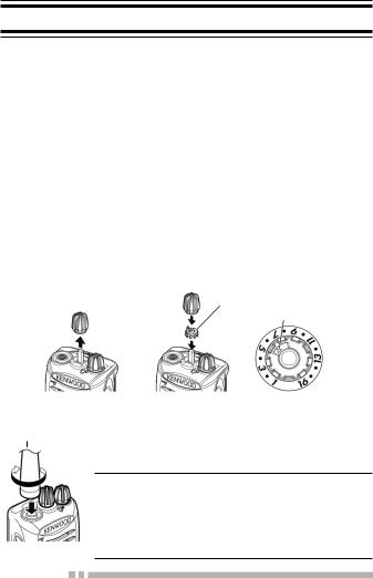
INSTALLING THE CHANNEL STOPPER
You can set the channel stopper position for channels 2, 4, 6, 8, 10, 12, and 14. Inserting the Channel stopper prevents unnecessarily selecting channels which do not exist.
•Selecting a channel which does not exist causes a continuous error tone to sound.
1Set the Channel selector to channel 1, then pull the Channel selector knob off the transceiver.
•If the Channel selector is not positioned at channel 1, the knob may not install correctly and the channel may be unable to change.
2Insert the channel stopper.
3Set the arrow of the Channel stopper to the highest channel number for the transceiver.
4Reinsert the Channel selector knob.
Channel stopper
Arrow
INSTALLING THE ANTENNA
Antenna Screw the antenna into the connector on the top of the transceiver by holding the antenna at its base and turning it clockwise until secure.
Note:
The antenna is neither a handle, a key ring retainer, nor a speaker/ microphone attachment point. Using the antenna in these ways may damage the antenna and degrade your transceiver’s performance.

 2
2
INSTALLING/ REMOVING THE BATTERY PACK
Do not short the battery terminals or dispose of the battery by fire.
Never attempt to remove the casing from the battery pack.
1Align the battery pack with the back of the transceiver, then press the battery pack and transceiver firmly together until the release latch on the base of the transceiver locks.
2To remove the battery pack, lift the safety catch on the base of the transceiver, then press the release latch underneath the safety catch.
3While pressing the release latch, pull the battery pack away from the transceiver.
INSTALLING THE BELT CLIP
If necessary, attach the belt clip using the two supplied M3 x 8 mm screws.
Note:
If the belt clip is not installed, its mounting location may get hot during continuous
|
|
Belt clip |
transmission or when left sitting in a hot |
|
|
environment. |
|
|
|
|
|
|
|
|
|
|
|
|
|
|
|
|
|
Do not use glue which is designed to prevent screw loosening when installing the belt clip, as it may cause damage to the transceiver. Acrylic ester, which is contained in these glues, may crack the transceiver’s back panel.
3
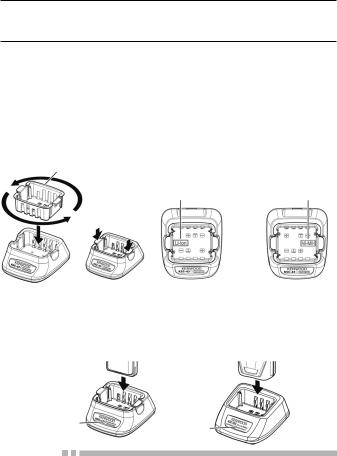
CHARGING THE BATTERY PACK (OPTIONAL BATTERY CHARGER)
The battery pack is not charged at the factory; charge it before use.
ATTENTION:
Always switch OFF a transceiver equipped with a battery pack before inserting the transceiver into the charger.
1Plug the AC adapter cable into the jack located on the rear of the charger.
2Plug the AC adapter into an AC outlet.
3Match the Holder to the type of battery pack to be charged so that when inserting the Holder, the battery type name can be seen on the bottom of the charger. After inserting the Holder into the charger, press the locking tabs to secure it in place. <KSC-43 only>
Holder
Li-ion battery |
Ni-MH battery |
charger |
charger |
•To remove the Holder, squeeze the locking tabs together then pull the Holder out of the charger. <KSC-43 only>
4Slide a battery pack or a transceiver equipped with a battery pack into the charging slot of the charger.
Indicator |
Indicator |
|

 4
4
•Make sure the metal contacts of the battery pack mate securely with the charger terminals.
•The indicator lights red and charging begins.
5When charging is completed, the indicator lights green. Remove the battery pack or the transceiver from the charging slot of the charger.
•It takes approximately 3 hours to charge the battery pack.
•When the charger will not be used for a long time, unplug the AC adapter from the AC outlet.
Note:
When the indicator blinks red, the battery pack is either defective or the battery pack contacts are not properly mated with those of the charger.
When the indicator flashes green and orange, the battery pack has not satisfied the charging start temperature. Remove the battery pack from the charger and wait until it reaches a normal temperature before charging it again.
The ambient temperature should be between 5°C and 40°C while charging is in progress. Charging outside this range may not fully charge the battery.
The battery pack life is over when its operating time decreases even though it is fully and correctly charged. Replace the battery pack.
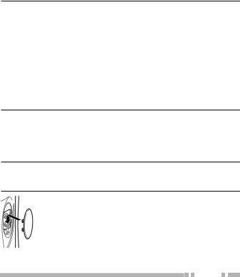
INSTALLING THE CAP OVER THE SPEAKER/ MICROPHONE JACKS
Install the cap over the speaker/ microphone jacks when not using an optional speaker/ microphone.
Note:
To keep the transceiver water resistant, you must cover the speaker/ microphone jacks with the supplied cap.
1Place the cap over the jacks so that the locking tabs insert into the transceiver grooves.
5
2While holding the cap in place, push it towards the bottom of the transceiver until the tabs on the cap click into place.
•To remove the cap, hold the top of the cap in place with your finger while inserting a 2 mm or smaller flat blade screwdriver under the bottom of the cap. Slowly slide the screwdriver in until its tip touches the tab inside the cap, then gently pry the cap
up (handle of screwdriver moving away from the transceiver) to remove the cap.
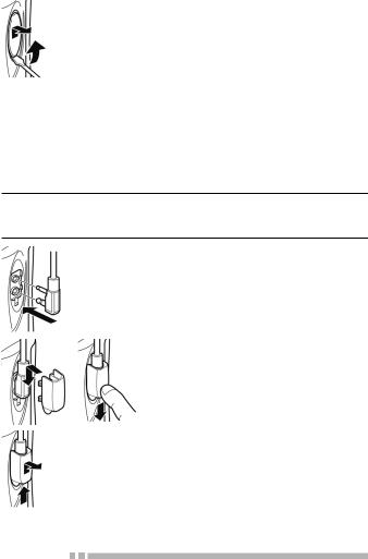
INSTALLING THE OPTIONAL SPEAKER/ MICROPHONE (OR HEADSET)
Note:
The transceiver is not fully water resistant when using a speaker/ microphone or headset.
1Insert the speaker/ microphone (or headset) plugs into the speaker/ microphone jacks of the transceiver.
2Place the locking bracket over the speaker/ microphone (or headset) plugs so that the locking tabs insert into the transceiver grooves.
•Push down on the locking bracket to slide it into place.
3While holding the locking bracket in place, push it towards the bottom of the transceiver until the tabs on the bracket click into place.
•To remove the locking bracket, push the bracket up from the base.

 6
6
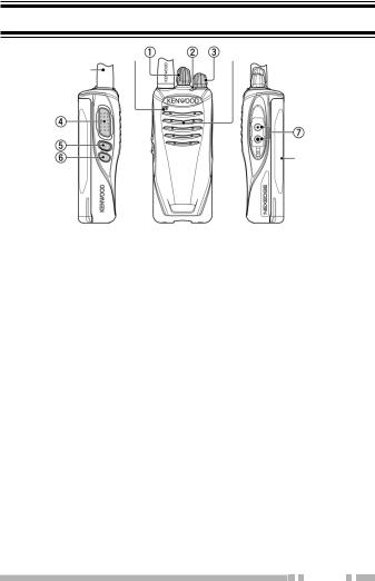
ORIENTATION
Microphone |
Speaker |
Antenna |
|
Battery pack
aChannel selector
Rotate to change the operating channel.
bLED indicator
Refer to the LED indicator status. {p. 13}
cPower switch/ Volume control
Turn clockwise to switch ON the transceiver. To switch OFF the transceiver, turn counterclockwise until a click sounds. Rotate to adjust the volume level.
dPTT (Push to Talk) switch
Press and hold, then speak into the microphone to transmit.
eSide 1 key
Press to activate its programmable function. {page 8}
fSide 2 key
Press to activate its programmable function. {page 8}
gSpeaker/ microphone jacks
Insert the Speaker/ microphone or Headset plug into this jack. {page 6}
7

PROGRAMMABLE AUXILIARY FUNCTIONS
Your dealer can program the Side 1 and Side 2 keys each with one of the functions listed below.
Note:
The duration of pressing a key to activate a function is dependent on your dealer setting. Your dealer may have set some keys to be held down for a short duration instead of being momentarily pressed. Ask your dealer for details on which keys need to be held down to activate their functions.
■None
No function has been programmed.
■Autodial 1
Autodial allows you to make a private DTMF call to another party.
■Call 1/ Call 2
Press to send a FleetSync status, NXDN status, NXDN individual, 2-tone signaling call.
■Calling Alert 1
A calling alert tone allows you to alert party members that you are making a call. When making a call, first hold down this key.
•While holding down the key, the calling alert tone will sound. Release the key to end the tone, then hold down the PTT switch and speak into the microphone to transmit.
■CW Message 2
Press to transmit the preset Morse code message on your current channel.
■Emergency
Press and hold to enter (or exit) Emergency mode.
■Key Lock
Press to lock/unlock the transceiver keys. Without Status Memory, when the transceiver power is turned OFF and then ON again, the Key Lock function will be canceled.

 8
8
 Loading...