

Kenwood DMS-500 Owners manual

MINIDISC RECORDER
JA
DM-S500
INSTRUCTION MANUAL
KENWOOD CORPORATION
B60-3554-00 (K, P, T, M ) MC
98/12 11 10 9 8 7 6 5 4 3 2 1 97/12
Introduction
DM-S500 (En)
Before applying power
Caution : Read this section carefully to ensure safe operation.
2
Units are designed for operation as follows.
Australia ..................................................................................AC 240 V only
U.S.A. and Canada ................................................................AC 120 V only
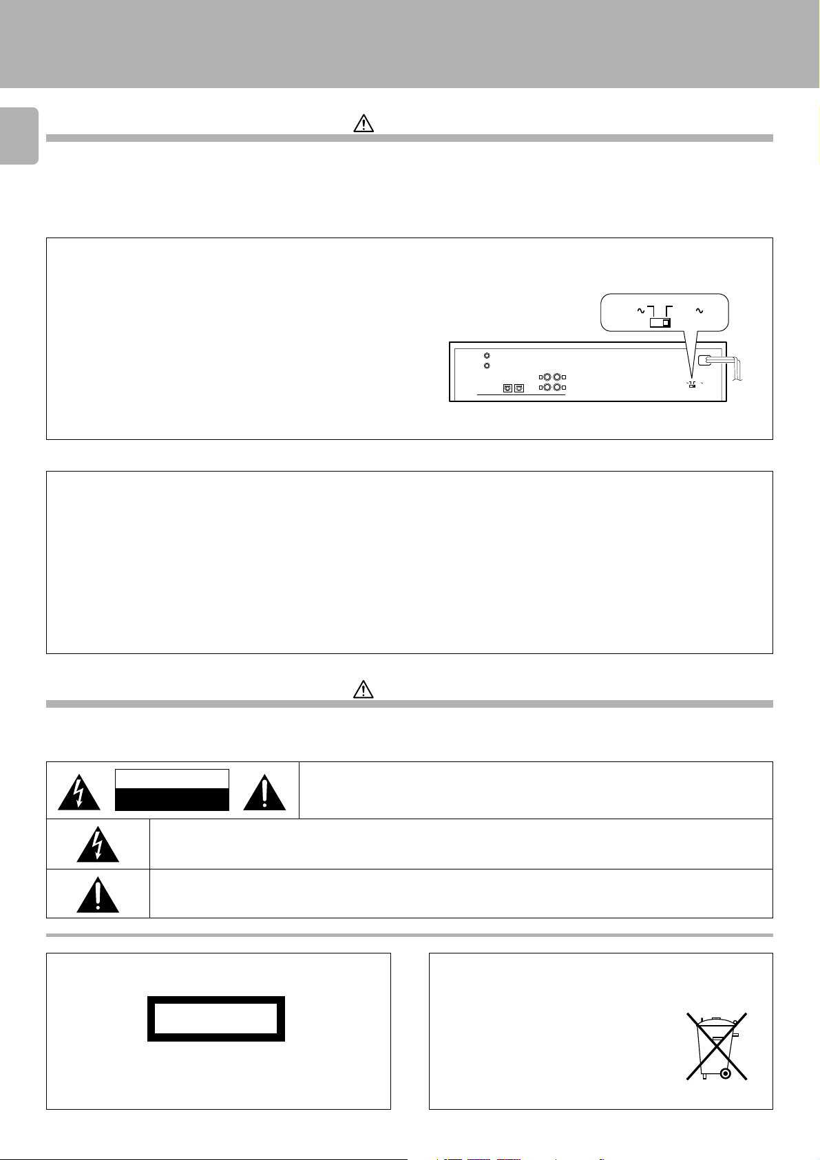
*AC voltage selection
The AC voltage selector switch on the rear panel is set to the voltage
that prevails in the area to which the unit is shipped. Before
connecting the power cord to your AC outlet, make sure that the
setting position of this switch matches your line voltage. If not, it
must be set to your voltage in accordance with the following
direction.
Note:
Our warranty does not cover damage caused by excessive line voltage
due to improper setting of the AC voltage selector switch.
For the United Kingdom
Factory fitted moulded mains plug
1. The mains plug contains a fuse. For replacement, use only a 13- Amp ASTA-approved (BS1362) fuse.
2. The fuse cover must be refitted when replacing the fuse in the moulded plug.
3. Do not cut off the mains plug from this equipment. If the plug fitted is not suitable for the power points in your home or the cable is too short to
reach a power point, then obtain an appro priate safety approved extension lead or adapter, or consult your dealer.If nonetheless the mains plug
is cut off, remove the fuse and dispose of the plug immediately, to avoid a possible shock hazard by inadvertent connection to the mains supply.
Europe and U.K. .....................................................................AC 230 V only
China ......................................................................................... AC 220 V only
*Other countries............................ AC 110-120 / 220-240 V switchable
AC voltage selector switch
AC 110120V
DIGITAL IN
SYSTEM
CONTROL
12
Move switch lever to match your line voltage with a
small screwdriver or other pointed tool.
LINE
PLAY
REC
OPTICAL
IN
LRL
OUT
R
AC 220240V
AC 110120V
AC 220240V
IMPORTANT :
The wires in the mains lead are coloured in accordance with the following code :
Blue : Neutral
Brown : Live
Do not connect those leads to the earth terminal of a three - pin plug.
Safety precautions
Caution : Read this section carefully to ensure safe operation.
WARNING : TO PREVENT FIRE OR ELECTRIC SHOCK, DO NOT EXPOSE THIS
APPLIANCE TO RAIN OR MOISTURE.
CAUTION
RISK OF ELECTRIC SHOCK
DO NOT OPEN
THE LIGHTNING FLASH WITH ARROWHEAD SYMBOL, WITHIN AN EQUILATERAL TRIANGLE, IS INTENDED TO ALERT THE
USER TO THE PRESENCE OF UNINSULATED “DANGEROUS VOLTAGE” WITHIN THE PRODUCT’S ENCLOSURE THAT MAY
BE OF SUFFICIENT MAGNITUDE TO CONSTITUTE A RISK OF ELECTRIC SHOCK TO PERSONS.
THE EXCLAMATION POINT WITHIN AN EQUILATERAL TRIANGLE IS INTENDED TO ALERT THE USER TO THE PRESENCE
OF IMPORTANT OPERATING AND MAINTENANCE (SERVICING) INSTRUCTIONS IN THE LITERATURE ACCOMPANYING
THE APPLIANCE.
The marking of products using lasers
(Except for some areas)
CAUTION: TO REDUCE THE RISK OF ELECTRIC SHOCK, DO NOT REMOVE COVER (OR
BACK). NO USER-SERVICEABLE PARTS INSIDE, REFER SERVICING TO QUALIFIED SERVICE
PERSONNEL.
REQUIREMENT BY NEDERLAND GAZETTE
CLASS 1
LASER PRODUCT
The marking is located on the rear panel and says that the component
uses laser beams that have been classified as Class 1. It means that
the unit is utilizing laser beams that are of a weaker class. There is no
danger of hazardous radiation outside the unit.
Batteries are supplied with this product. When
they empty, you should not throw away. Instead, hand them in as small chemical waste.

Introduction
DM-S500 (En)
Special features
This unit is audio equipment based on the Mini Disc format. The Mini Disc (MD) is an application of the optical and magneto-optical technology and
has the capability to record signals on discs.The operability of the MD is equivalent to the Compact Disc (CD). The MD uses optional non-contact
system so the recordings are not degraded by eternal factors and the discs are never scratched or damaged in playback.
Convenient title search
After recording of music tracks on a Mini Disc, their title can be registered
additionally. Once the titles have been registered, the desired music
tracks on the Mini Disc can be played by referring to the display, not the
record jacket, etc.
High-quality playback/recording
This unit incorporates a high-performance, 1-bit DAC for playback with a
high sound quality. Digital recording with a high sound quality is also
possible thanks to the optical input jack.
Convenient editing features
The contents of the disc recorded by yourself can be edited as you need.
÷ Reordering tracks
: The order of tracks can be changed by moving them as desired.
÷ Dividing a track
: A single track can be split into two by inserting an additional track number.
÷ Combining two tracks
: Two tracks can be merged into a single track by deleting a track number.
÷ Erasing tracks
: Music tracks or an entire disc you do not want to listen to can be erased, or all titles
are erased.
3

Introduction
DM-S500 (En)
Contents
4
Caution : Read the pages marked carefully to ensure safe operation.
Introduction................................................................................................................................................................................. 2
Before applying power ............................................................................................................................................................ 2
Safety precautions .................................................................................................................................................................. 2
Special features ....................................................................................................................................................................... 3
System connections .................................................................................................................................................................. 6
Names and functions of parts ................................................................................................................................................. 8
Display/Main unit ..................................................................................................................................................................... 8
Remote control unit ................................................................................................................................................................ 9
Operation of remote control unit .......................................................................................................................................... 10
Graphical Remote Control Unit(GRC) ................................................................................................................................... 11
Setting up the GRC for MD .................................................................................................................................................. 12
Playback of Mini Disc ............................................................................................................................................................ 14
Playing tracks in order from track No. 1 ............................................................................................................................... 14
Playback from desired track .................................................................................................................................................. 15
Listening in random order (RANDOM playback) .................................................................................................................. 15
Searching a desired track by its title (TITLE SEARCH) ......................................................................................................... 17
Programming tracks in a desired order ................................................................................................................................18
Repeated playback ................................................................................................................................................................20
TIME DISPLAY key ............................................................................................................................................................... 21
Recording .................................................................................................................................................................................. 22
Analog recording ................................................................................................................................................................... 22
Digital recording .................................................................................................................................................................... 24
Synchro recording with CD player ........................................................................................................................................26
Editing ........................................................................................................................................................................................ 27
Selecting the editing function type ....................................................................................................................................... 27
Changing tracks during playback (TRACK MOVE) ................................................................................................................ 28
Moving several tracks at a time (QUICK MOVE) .................................................................................................................. 30
Dividing a track during playback (TRACK DIVIDE) ................................................................................................................ 32
Combining tracks during playback (TRACK COMBINE) ....................................................................................................... 34
Erasing several tracks at a time (QUICK ERASE) ................................................................................................................. 36
Erasing a single track during playback (TRACK ERASE) ......................................................................................................38
Erasing a part of a track ........................................................................................................................................................ 39
How to edit titles .................................................................................................................................................................. 40
Changing or deleting a title ................................................................................................................................................... 42
CD Text Editing ......................................................................................................................................................................... 44
Important items ........................................................................................................................................................................ 45
Safety Precautions ................................................................................................................................................................ 45
Maintenance .......................................................................................................................................................................... 46
MD system ............................................................................................................................................................................ 47
Digital recording and SCMS .................................................................................................................................................. 48
In case of difficulty.................................................................................................................................................................. 49
Specifications .......................................................................................................................................................................... 52
Introduction
DM-S500 (En)
Unpacking
Unpack the unit carefully and make sure that all accessories are put aside so they will not be lost.
Examine the unit for any possibility of shipping damage. If your unit is damaged or fails to operate, notify your dealer immediately. If your unit was shipped
to you directly, notify the shipping company without delay. Only the consignee (the person or company receiving the unit) can file a claim against the
carrier for shipping damage.
We recommend that you retain the original carton and packing materials for use should you transport or ship the unit in the future.
Keep this manual handy for future reference.
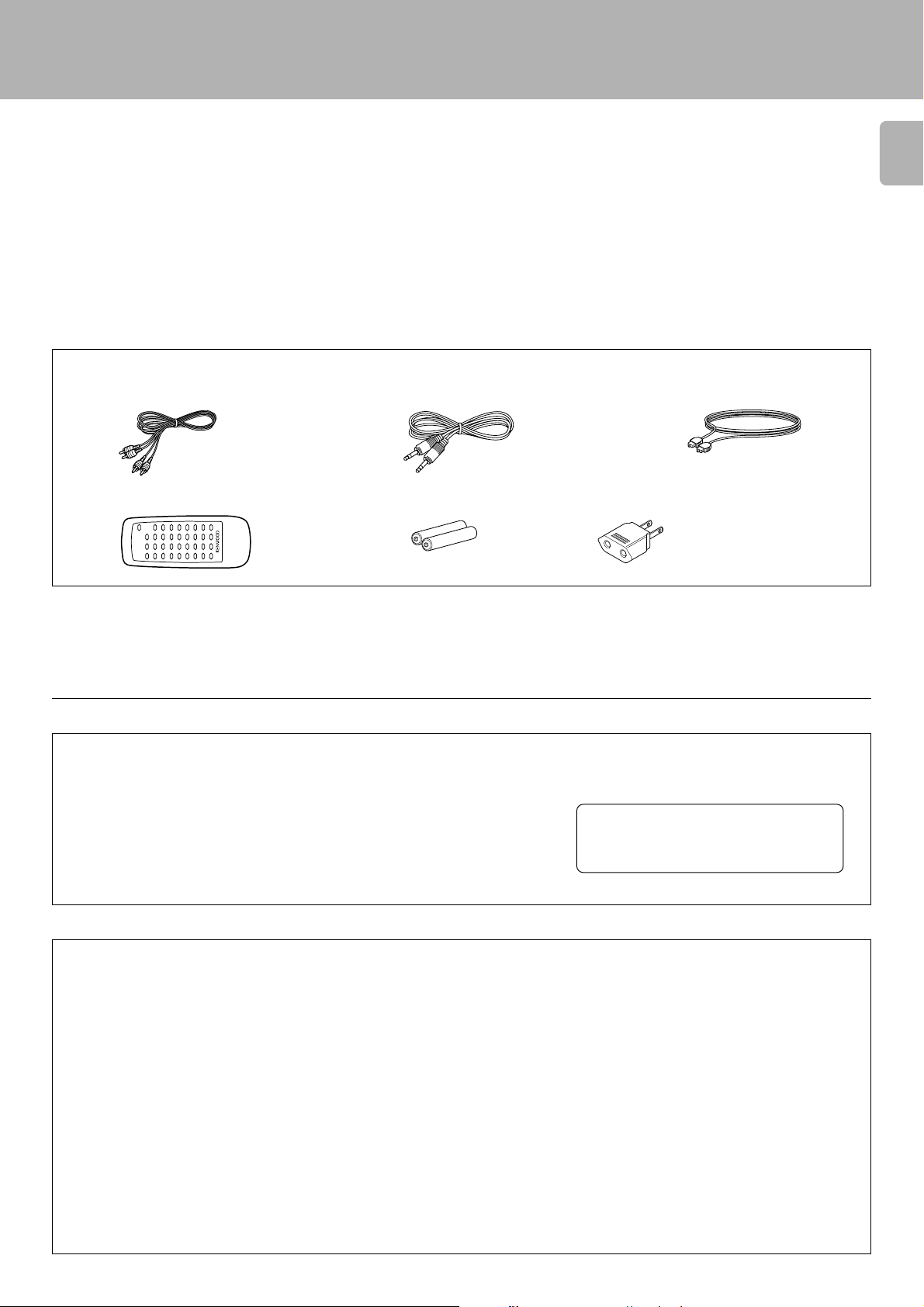
Accessories
Check that the following accessories are present.
Audio cord (2)
System control cord (1)
Optical fiber cable (1)
5
Remote control unit (1) Batteries (2)
For the U.S.A.
CAUTION :
Use of controls or adjustments or performance of procedures other than those
specified herein may result in hazardous radiation exposure.
In compliance with Federal Regulations, following are reproductions of labels on, or
inside the product relating to laser product safety.
For the U.S.A.
AC plug adaptor (1)
Use to adapt the plug on
the power cord to the
shape of the wall outlet.
(Accessory only for regions
where use is necessary.)
- - - - - - - - - - - - - - - - - - - - - -
KENWOOD CORPORATION
2967-3, ISHIKAWA-CHO, HACHIOJI-SHI,
TOKYO, JAPAN
KENWOOD CORP. CERTIFIES THIS
EQUIPMENT CONFORMS TO DHHS
REGULATIONS NO. 21 CFR 1040.10,
CHAPTER I, SUBCHAPTER J.
Location: Back Panel
- - - - - - - - - - -
- - - - - - - - - - - - - - - - - - - - - -
- - - - - - - - - - - -
FCC WARNING :
This equipment may generate or use radio frequency energy. Changes or modifications to this equipment may cause harmful
interference unless the modifications are expressly approved in the instruction manual. The user could lose the authority to operate
this equipment if an unauthorized change or modification is made.
NOTE :
This equipment has been tested and found to comply with the limits for a CLASS B digital device, pursuant to Part 15 of the FCC
Rules. These limits are designed to provide reasonable protection against harmful interference in a residential installation. This
equipment may cause harmful interference to radio communications, if it is not installed and used in accordance with the
instructions. However, there is no guarantee that interference will not occur in a particular installation. If this equipment does cause
harmful interference to radio or television reception, which can be determined by turning the equipment off and on, the user is
encouraged to try to correct the interference by one or more of the following measures:
— — Reorient or relocate the receiving antenna.
— — Increase the separation between the equipment and receiver.
— — Connect the equipment into an outlet on a circuit different from that to which the receiver is connected.
— — Consult the dealer or an experienced radio/TV technician for help.
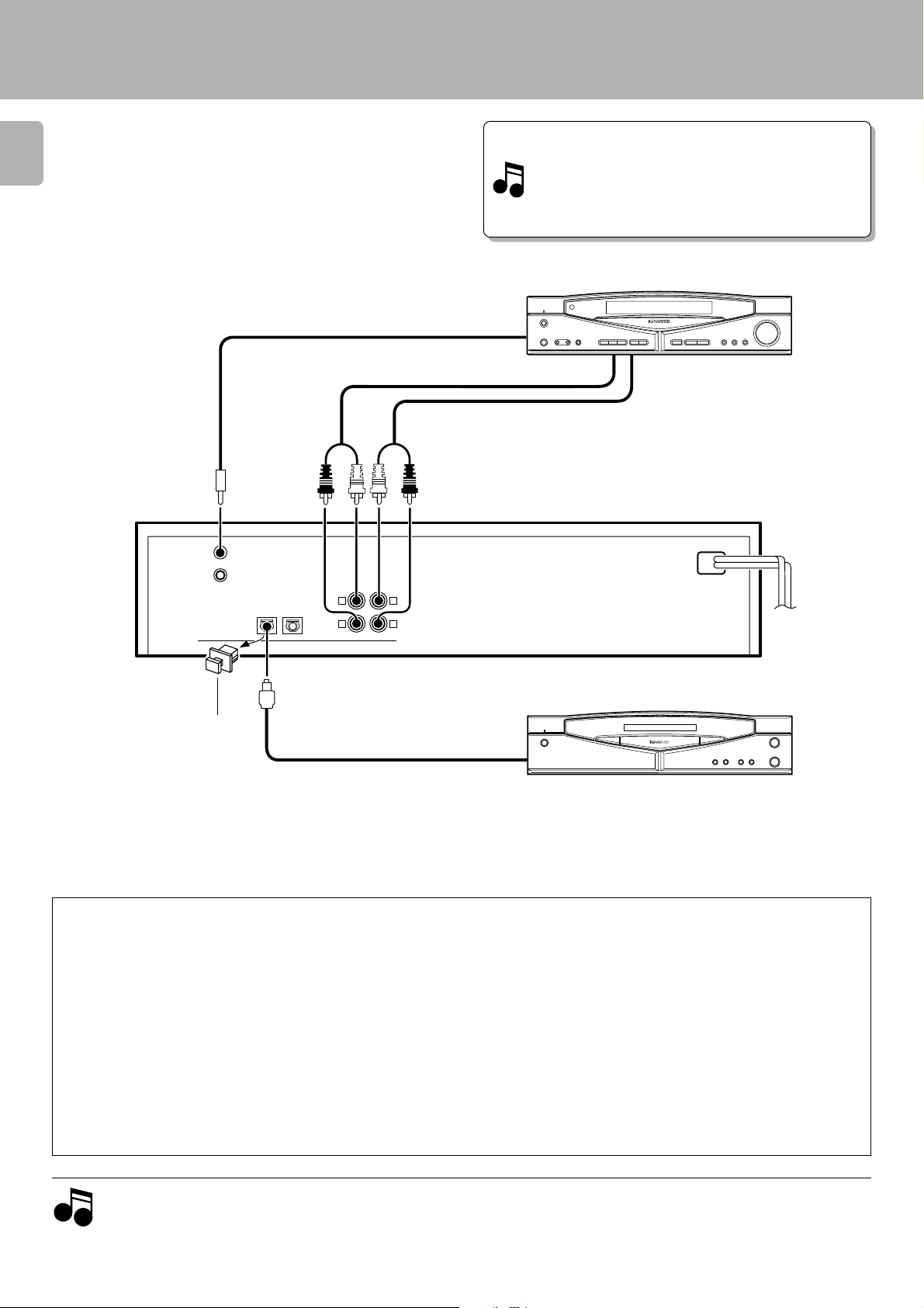
System connections
Make connection as shown below. When connecting the
related system components, refer also to the instruction
6
manuals of the related components.
Caution: Do not plug in the power lead until all connections
are completed.
System control cord
Audio cord
Malfunction of microprocessor
To SYSTEM CONTROL
terminal
DM-S500 (En)
If operation is not possible or erroneous display appears
even though all connections have been made properly,
reset the microprocessor referring to “In case of diffi-
culty”. o
AV CONTROL CENTER (sold separately)
or receiver (sold separately)
REC OUT PLAY IN
Connect to TAPE 1/MD or
TAPE 2 MONITOR terminal
(*1).
LINE
PLAY
REC
OUT
IN
L
R
L
R
DIGITAL OUTPUT
(OPTICAL)
SYSTEM
CONTROL
before using the DIGITAL IN
jack.
DIGITAL IN
OPTICAL
12
Optical fiber cableRemove the protective cap
÷ For CD recording, the CD-TEXT function, and for positive system
operation, connect the CD player to “DIGITAL IN OPTICAL 1”.
¢§
÷ Commercial digital equipment (BS tuner, DAT, etc.) can be connected
to “OPTICAL 2”.
Connection to the TAPE 1/MD jacks
The following setup allows to combine this unit with the Series 21
system and control it as a part of a single system.
Connect a system control cord to this unit and to one of the
1
system components connected using other system control
cords (AV Control Center, CD player or cassette deck).
Connect an audio cord to the TAPE 1/MD jacks of the AV Control
2
Center or receiver.
Set the input function of the AV Control Center or receiver to
3
“MD”.
÷ Refer to the instruction manual of the AV Control Center or receiver
for details.
(*1)
TO WALL AC
OUTLET
Digital component (CD player, etc.)
The above illustration is simply an example.
The actual connected equipment may vary depending on
the sales region.
Connection to the TAPE 2 MONITOR jacks
The system control is not available when the audio cord is connected to the TAPE 2/MONITOR jacks. In this case, do not connect
a system control cord to this unit; otherwise malfunction will
result.
To control this unit using the GRC-151, GRC-102 or GRC-101 (optional),
select “IR” in the Setup MD menu.
(*1)
@
To control the system using the GRC-151, GRC-102 or GRC-101
(optional), select “System Control” in the Setup MD menu.
@
1. Connect all cords firmly. If connections are loose, there could be loss of sound or noise produced.
Notes
Notes
2. When plugging and unplugging connection cords, be sure to first remove the power cord from the AC outlet. Plugging/unplugging
connection cords without removal of the power cord can cause malfunctions or damage to the unit.
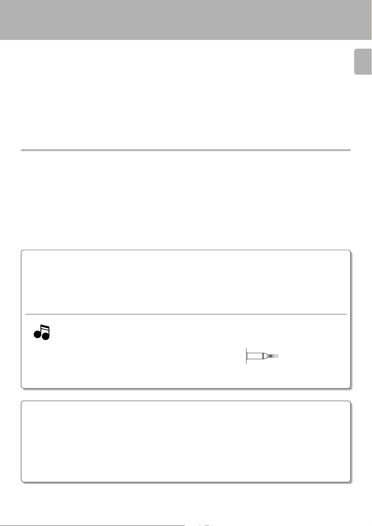
Note on connection of optical-fiber cable
The optical-fiber cable is designed for use in the connection of the
CD player. The digital signal transmission makes it possible to
record the high-quality sound of CDs without degradation.
÷ Insert the optical-fiber cable straight into the connector until it clicks.
÷ Be sure to attach the protection cap when the connector is not used.
÷ Never bend or bundle the optical-fiber cable.
System connections
DM-S500 (En)
7
SYSTEM CONTROL CONNECTIONS
After hooking this unit up with the KENWOOD System “SERIES 21,” connect the system control cords for convenient system control
operations between the connected devices.
When hooking this unit up with the System “SERIES 21,” read the instruction manuals supplied with the AV CONTROL CENTER (sold
separately) or the receiver (sold separately).
Notes
Notes
1. Do not connect system control cords to any components other than
those specified by KENWOOD. It may cause a malfunction and
damage your equipment.
2. Be sure the system control plugs are inserted all the way in to the
system control terminals.
SYSTEM CONTROL OPERATIONS
Remote Control
Lets you operate this unit with the system remote control unit (GRC-151, GRC-102 or GRC-101).
Automatic Operation
Automatically switches the input selector on the AV CONTROL CENTER or receiver when you start playback from this unit.
Synchronized Recording
Lets you synchronize recording with the start of playback when recording from CD.
See the operating instructions supplied with your CD player or VIDEO-CD LD player for details.
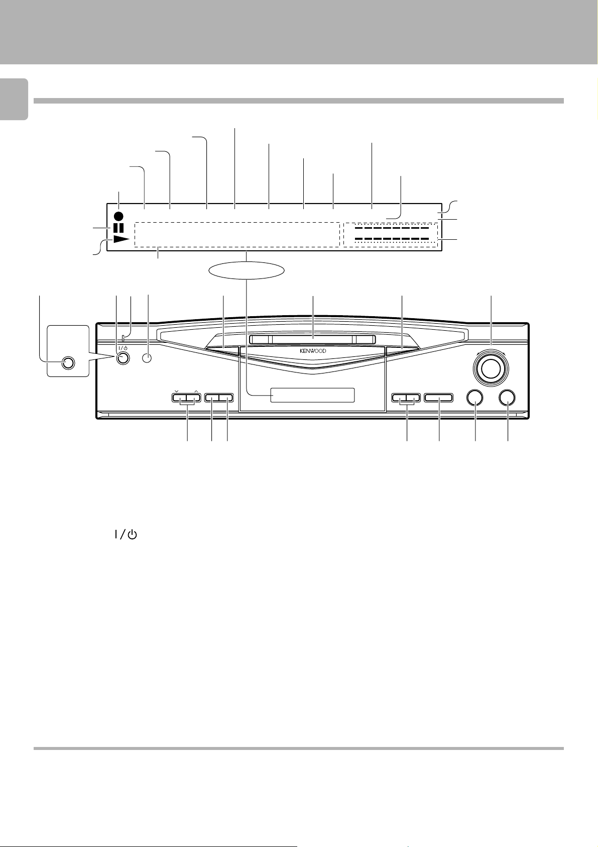
Names and functions of parts
Display/Main unit
8
TOTAL indicator
Pause indicator
Play indicator
For U.S.A.
and Canada
POWER
ON/STANDBY
SINGLE indicator
REPEAT indicator
PGM indicator
REC indicator
PGM
•
Character information display
324 75611
ON/STANDBY
REPEAT
SINGLE
••••
REC
REC
LEVEL
INPUT
REMAIN indicator
TOTAL
•
Display
TIME
DISPLAY
÷REC
REMAIN
•
TITLE indicator
TITLE
•
••
MINI DISC RECORDER DM-S500
SEARCH
indicator
SEARCH
DIGITAL input indicator
CD TEXT indicator
DIGITAL 1 2
CD TEXT
L
∞
R
3
0
MANUAL
MONITOR
(
−
dB)
0130105
¡1
MANUAL indicator
MONITOR indicator
Peak level indicator
8
DM-S500 (En)
SHUTTLE
¢4
73
890 # $@!
1 ON/STANDBY ( ) key $
Press to turn the unit on or off (standby).
1 POWER key (For U.S.A. and Canada) $
Press to turn the unit on or off.
2 Standby indicator
3 Remote control sensor 0
The key control signals from the remote control unit enter the main
unit from here.
4 TIME DISPLAY key ¡
5 Mini Disc insertion slot $
Insert a minidisc.
6 Eject (0) key ^
Press to unload the Mini Disc.
7 SHUTTLE (4, ¢) knob ^
Use to skip disc tracks during playback.
During editing, this knob is used to select track numbers, title and
characters.
•‚q
8 REC LEVEL keys ™
This key is used to adjust the recording level.
9 REC INPUT key ™
This key is used to switch the recording input source.
0 REC (¶) key £
Press when starting recording.
! Fast forward and fast backward (1, ¡) ^
During playback, this key is used to move the played position forward
or backward.
At the time of editing, the cursor movement and the selected title can
be confirmed.
¶ºflq
@ Pause (8) key ^
Press to temporary stop the disc operation.
# Stop (7) key ^
Press to stop the disc operation.
$ Play (3) key $
Press to start playback.
About the STANDBY mode
While the STANDBY indicator is lit on the display, a small amount of power is supplied to the system to back up the memory. This is called the standby
mode. Under that condition, the system can be turned ON by the remote control unit.
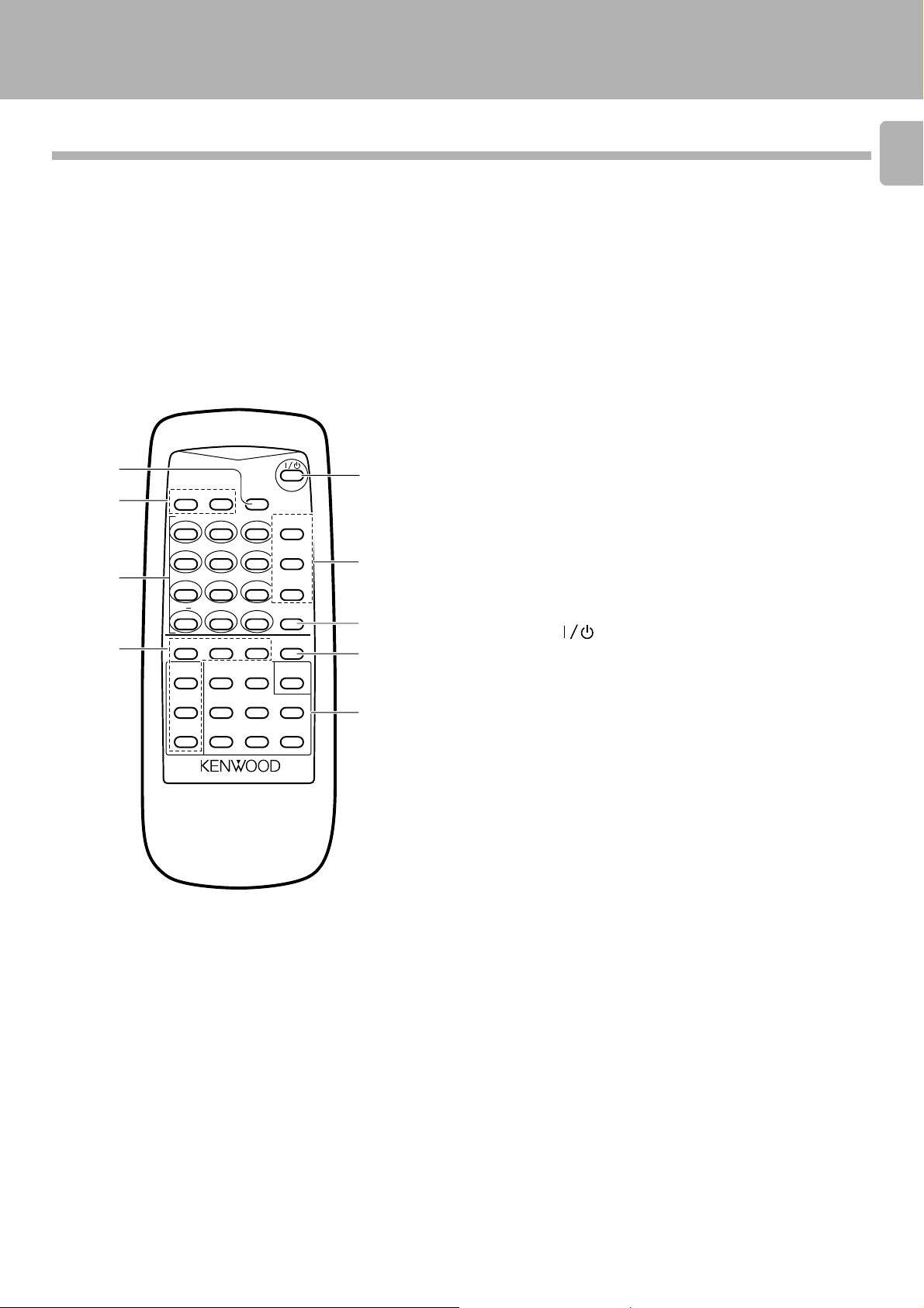
Names and functions of parts
DM-S500 (En)
Remote control unit
RC-M0502
1
2
3
4
REPEAT
RANDOM
ABC DEF
123
GHI JKL MNO
456
PRS TUV WXY
789
/
&
QZ
i j
+100 0 +10
EDIT
SET
TITLE
CURSOR/CHECK
INPUT
1¡
TITLE
4¢
SEARCH
EDIT
7
CANCEL
REMOTE CONTROL UNIT
Model: RC-M0502
Infrared ray system
POWER
TIME
DISPLAY
P.MODE
CHARACTER
CHECK
SPACE
CLEAR
DELETE
f,FHI
REC
INPUT
ENTER MONITOR
AUTO/
MANU.
3
¶
8
5
6
7
8
9
1 TIME DISPLAY key ¡
: Press to switch the time display mode.
2 Applied operation keys
RAMDOM key %
: Used at the time of random playback.
REPEAT key )
: Press to play tracks repeatedly.
3 Numeric keys
: Press to specify the desired track number. %
: Used at the time of title input for selection of characters and
symbols.
qw
4 Edit operation keys
EDIT key •
: This key is used to switch the editing mode.
SET key •
: Press to set the editing result or input title definitely in memory.
ENTER key ª
: Press to execute editing or title input operation.
TITLE INPUT key ‚
: This key is used to switch the title input mode.
TITLE SEARCH key &
: This key is used to switch the title search mode.
EDIT CANCEL key ª
: Used to cancel editing.
5 POWER ( ) key
: Press to turn the unit on or off (standby).
6 Program operation keys
P.MODE (Play mode)/CHARACTER key *q
: This key is used in program playback. During title input, it is used to
select the character group.
CHECK/SPACE key (e
: This key is used to check the program contents.
During title input, it is used to insert a blank space character.
CLEAR/DELETE key (w
: This key is used to clear the program. During title input, it is used to
delete a character.
7 REC INPUT (Recording input) key ™
: This key is used to switch the recording input source.
8 MONITOR key ∞
: The sound of the unit connected to “DIGITAL 2” is heard.
9 Basic operation keys
CURSOR/CHECK
1¡: Fast forward and fast backward keys. ^
(Same function as the keys on the main unit.)
4¢: Skip keys.
^
(Same function as the knob on the main unit.)
¶ : Record key 8 : Pause key
7 : Stop key 3 : Play key
AUTO/MANU. key ™¢
: This is used for selection of automatic (AUTO) or manual (MANU.)
track number assignment at the time of recording.
9
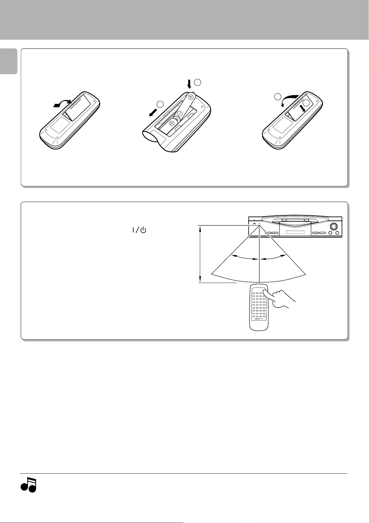
Operation of remote control unit
2
1
Loading batteries
10
Remove the cover.
1
Operation
Insert batteries.
2
1
÷ Insert two R6 (“AA”-size) batteries following
the polarity indications.
DM-S500 (En)
Close the cover.
3
2
The unit can be turned on by plugging the power cord into
a power outlet and pressing the POWER (
remote control unit. After the unit has been turned on, press
the desired operation key.
÷ When pressing more than one remote control keys successively,
press the keys securely by leaving an interval of 1 second or more
between pressing of keys.
) key of the
6 m
Remote sensor
30°
30°
Reference operating range
Notes
Notes
1. The provided batteries are intended for use in operation checking, and their service life may be short.
2. When the remote controllable distance becomes short, replace both of the batteries with new ones.
3. If direct sunlight or the light of a high- frequency fluorescent lamp (inverter type, etc.) is incident to the remote sensor, malfunction may
occur. In such a case, change the installation position to avoid malfunction.
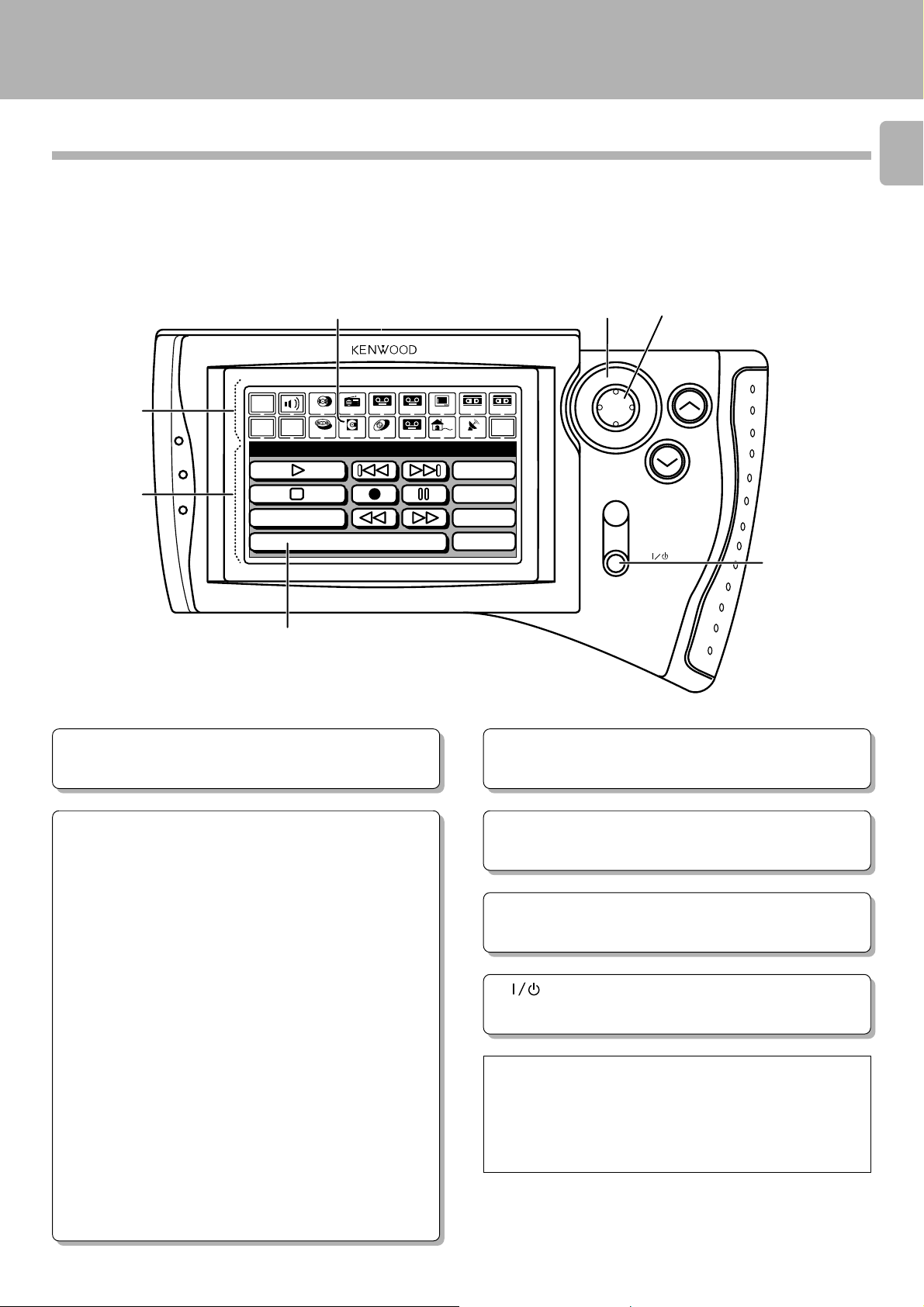
Operation of remote control unit
DM-S500 (En)
Graphical Remote Control Unit (GRC)
A graphical remote control (GRC-151, GRC-102 or GRC-101) is sold separately.
To enable remote control operation, simply connect this unit, cassette deck (sold separately), and other accessories to the AV
CONTROL CENTER with the system control cords.
54
MUTE
ON /STANDBY
VOLUME
6
1
2
Main
Menu
Confirm
Return
MD
Power
Title Search
3
TV
Tuner
CD
TapeBTapeA
Tape1
LDMDDVD
VCR2VCR1
Set Up
Sat.Cable
10key
PGM
Mode
Edit
REMOTE CONTROL UNIT
ENTER
11
3
Model : GRC-151, GRC-102 or
GRC-101
Infrared ray system
1 Segment screen
This screen is used for selecting the icons for the main equipment.
2Menu screen
This screen is used for selecting the icons for the operating modes.
MD recorder operation panel
Play icon (3)
Pause icon (8)
Stop icon (7)
Search icons (1, ¡)
These icons send the track forward or backward.
Mode icon
This icon is used to select the playback mode.
Skip icons (4, ¢)
When selected, the next track in the icon direction is played.
10key Pad icon
This icon switches to the Numeric Icon menu screen.
Power icon
This icon is used to turn the unit on or off. You can use this icon
only when you select “IR” in the setup menu.
Rec icon (¶)
This icon is used for recording.
PGM icon
This icon is used for program playback.
Edit icon
This icon is used to select the editing mode.
Title Search icon
This icon is used to switch the title search mode.
3 Icons
Icons for the equipment used and operating mode are displayed.
4 Joystick
The joystick is used when selecting the icons.
(Lightly press the edge of 5.)
5 ENTER key
Press this button to input the selected icon (operation mode, and
so on).
6 (ON/STANDBY) key
This key turns ON/STANDBY this unit or the equipment connected with the system control cords.
If your GRC unit is the GRC-100 or GRC-150
If the GRC unit provided with your AV CONTROL CENTER
(optional) or receiver (optional) is the “GRC-100” or “GRC150”, the DM-S500 unit should be controlled using the
remote control unit provided with this unit.
Operation of remote control unit
DM-S500 (En)
Preparation
÷ Turn the system devices ON.
12
You may skip Step 1 if the settings for the AV CONTROL CENTER
have already been made.
Once the settings have been made in Steps 1 to 3, you do not need
to repeat these steps until you replace the batteries.
GRC operation
The
beginning on page 14 are written assuming
that the basic operations below have been completed.
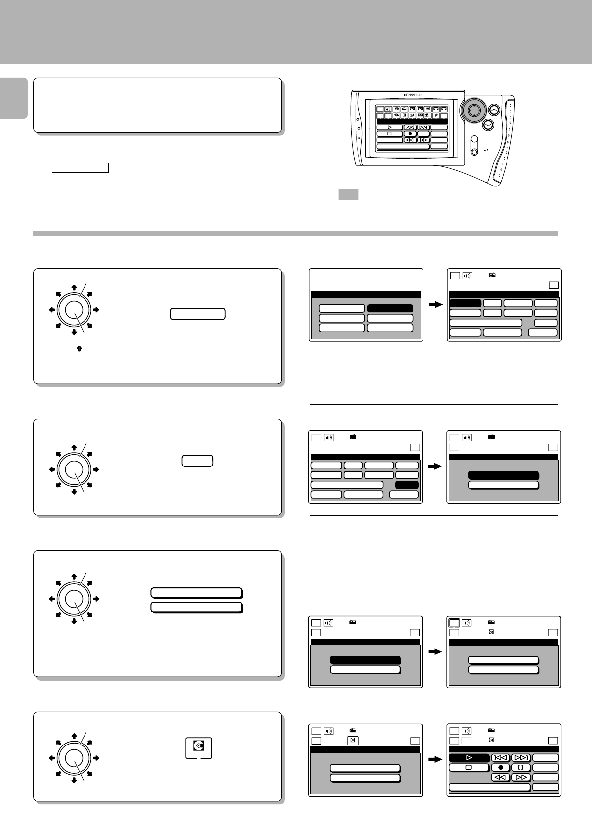
Setting up the GRC for MD
At the initial screen, select the Model Type to
1
be used.
Use the joystick to select the model type.
1
ENTER
2
The arrow ( ) shows
the direction that the
cursor moves when
selecting icons.
1
Example:
Model 4
Press the ENTER key to set the entry.
2
Main
Menu
Return
MD
Power
CD
Confirm
Title Search
Tuner
LDMDDVD
Tape1
REMOTE CONTROL UNIT
Sat.Cable
10key
PGM
Mode
Edit
Set Up
VCR2VCR1
TV
TapeBTapeA
ENTER
VOLUME
MUTE
ON /STANDBY
: Keys and control used in the operations described
on this page.
Select Screen after selection
Main
Model
Model 1
Model 2
Model 3
Type Setu
p
Model 4
Model 5
Model 6
Menu
Setup
C D
DVD/6ch Input
Sound Speaker
Sat.
L D
T V
Tuner
Tape1
Cable
Set Up
VCR1
VCR2
MD
Reset
÷ The selected icon is highlighted.
÷ If the model type has already been selected, select the Setup icon to
display the Setup menu.
Select MD at the Setup menu screen.
2
Use the joystick to select the MD icon.
1
1
ENTER
Press the ENTER key to set the entry.
2
MD
2
Select the control mode at the Setup MD
3
menu screen.
Use the joystick to select the control
1
ENTER
2
1
mode.
System Control
IR
Press the ENTER key to set the entry.
2
The selected text moves to the bottom right
of the screen.
Select Screen after selection
Main
Menu
Setup
C D
DVD/6ch Input
Sound Speaker
Sat.
Tuner
L D
T V
Tape1
Cable
Set Up
VCR1
VCR2
MD
Reset
Main
Menu
Return
Setup MD
Tuner
System Control
IR
Set Up
“System Control”: To be selected when this unit is connected to the
Series 21 system through a control cord. With this selection, point the
remote control unit to the remote sensor of the AV Control Center or
receiver.
“IR”: To be selected when the system control cord connection is not
used. With this selection, point the remote control unit to the remote
sensor of this unit.
Select Screen after selection
Main
Menu
Return
Setup MD
Tuner
System Control
IR
Set Up
Main
Menu
Return
Setup MD
Tuner
MD
System Control
IR
6
Set Up
Select MD at the Segment screen.
4
Use the joystick to select the MD icon.
1
ENTER
1
Press the ENTER key to set the entry.
2
2
MD
Select
Main
Menu
Return
Setup MD
Tuner
MD
System Control
IR
Set Up
Screen after selection
Main
Menu
Return
MD
Confirm
Tuner
MD
Title Search
Set Up
10key
PGM
Mode
Edit
Operation of remote control unit
DM-S500 (En)
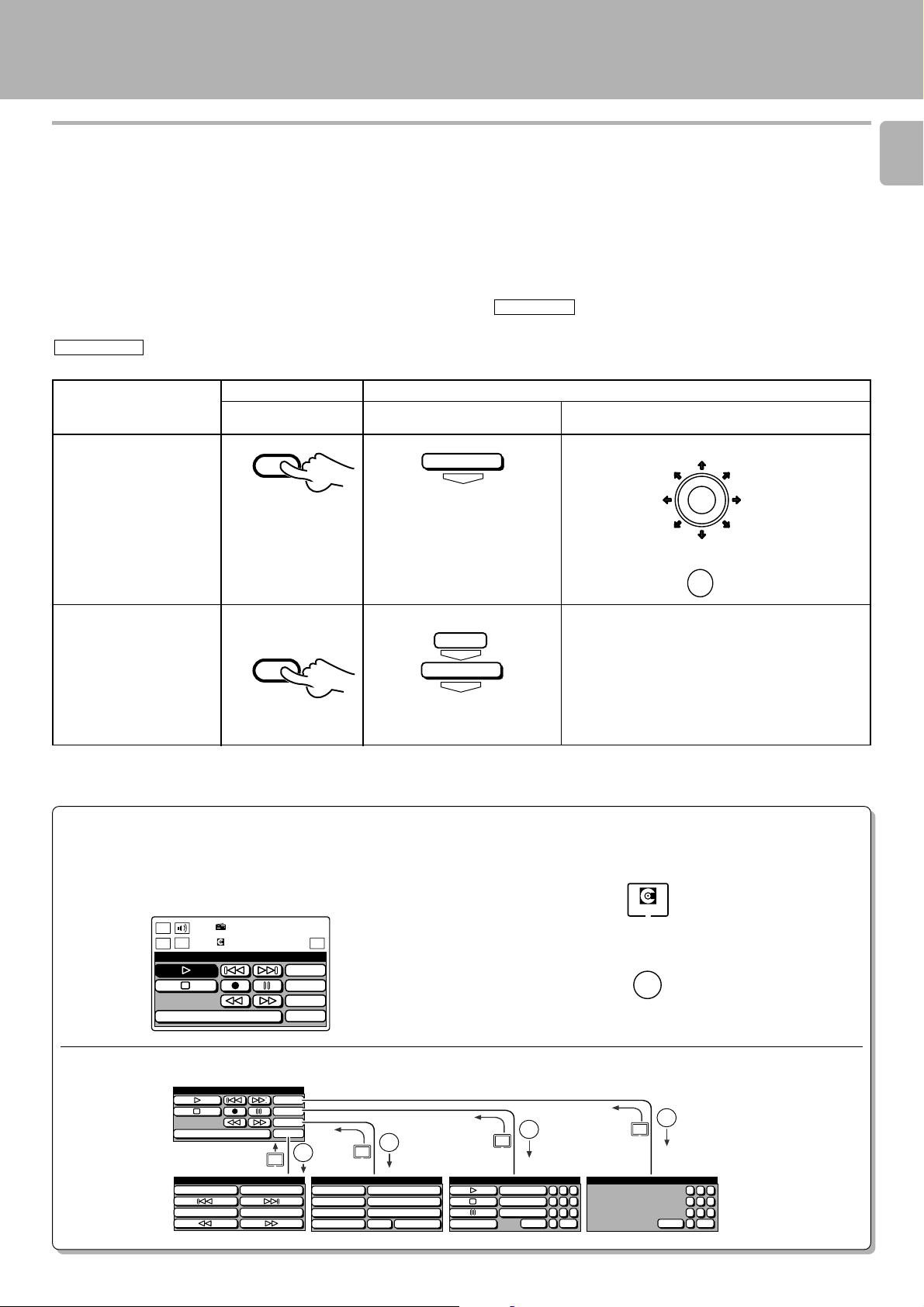
Notes on the remote control operating instructions in this text
This instruction manual for this model also covers the systems in the KENWOOD System “SERIES 21” lineup. Since the features
vary depending on the combined systems, the remote control operation illustrations (icons) are shown for two types of remote
control units.
To avoid a confusing and difficult-to-follow explanation of the graphical remote control unit, a simplified explanation is
provided using the operating instructions for a supplied remote control unit. Please reread the operating instructions while
referring to the main differences below.
13
Operations with the supplied remote control unit are indicated by
RC operation
.
Operations with the graphical remote control unit (Sepatrately sold: GRC-151, GRC-102 or GRC-101) are indicated by
GRC operation
Example of instruction
text in this manual
Press (select) the *** key.
Press the P.MODE key.
.
RC operation
Illustration
P.MODE
CHARACTER
Illustration of GRC operation in
this manual
GRC operation (GRC-151 , GRC-102 or GRC-101)
Actual GRC operation
Select *** by using joy stick.
1
ENTER
Press the ENTER key.
2
Select “PGM” icon.
1
Press the ENTER key.
PGM
ENTER
P.mode
ENTER
*1
2
Select “P.mode” icon.
3
Press the ENTER key.
4
÷ When using the GRC, you can return to the previous
menu screen (level) at any time by selecting the
ENTER
ENTER
Return icon, and pressing the ENTER key.
*1: Icons without shading send you to another menu screen (level) for the next operation. At
the new menu screen, you can select the desired icon.
Hints on Using the GRC
All of the procedures for the GRC operations start from the basic
operation screen. Although the explanation for going back to
this screen is omitted on each page, you can easily go to the basic
operation screen if you remember the following procedure.
Main
Menu
Return
MD
Tuner
Confirm
MD
Title Search
10key
PGM
Mode
Edit
Set Up
Basic operation screen.
MD menu structure
MD
Title Search
MD Edit
Edit
Enter
Set
Clear
Return
10key
PGM
Mode
Edit
ENTER
MD Mode
Random
Repeat
Display
Monitor
Return
Set
ENTER
Rec Input
Auto/Manual
Edit Cancel
Enter
Use the joystick to select the MD icon.
1
Press the ENTER key to set the entry.
2
ENTER
Return
MD PGM
Repeat
P.mode 1 2 3
Check
Clear
4 5 6
7 8 9
0 +10+100
10key Pad (MD)
ENTER
Return
MD
ENTER
1 2 3
4 5 6
7 8 9
0 +10+100
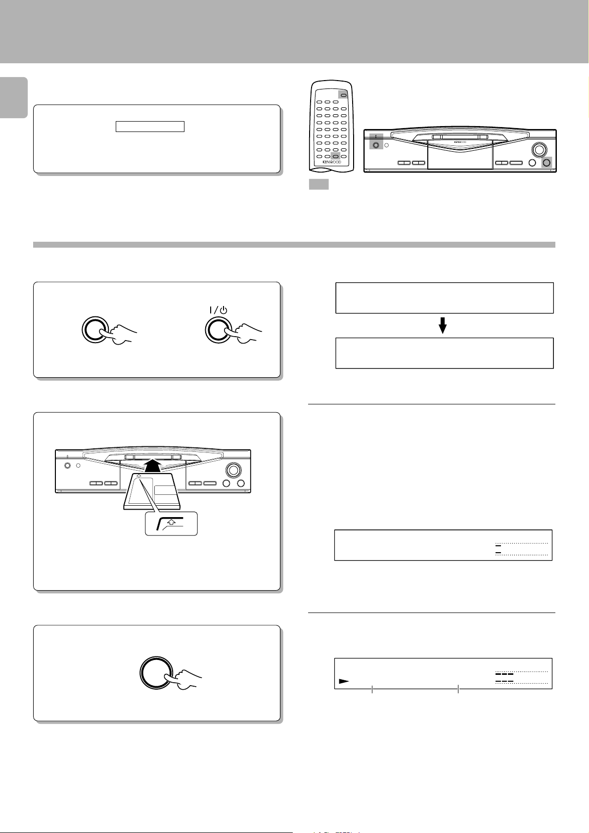
Playback of Mini Disc
ON/STANDBY
POWER
Use the following procedure to play a MD in the original
order of tracks from track No. 1.
14
Preparation
GRC operation
÷ Complete the procedure in “Setting up the
GRC for MD”.
: Keys and control used in the operations described on this page.
Playing tracks in order from track No. 1
Turn the unit ON.
1
DM-S500 (En)
For U.S.A. and Canada
Main unit
Load a Mini Disc.
2
Main unit
For other countries
ON/STANDBY
In the direction of the arrow.
-STANDBY-
L
In case no disc is loaded:
÷ Insert the minidisc correctly into the slot of this unit.
÷ “READING” blinks while the unit checks the contents of the disc.
÷ If a title has been assigned to the disc, that title will be displayed.
NO
SINGLE
0
01 0:00
D
ISC
R
L
R
3
∞
∞
0130105
(−dB)
3
0130105
(−dB)
3
Start playback.
Main unit
3
÷ In a few seconds, playback starts from track No, 1.
SINGLE
0
01 0:12
Track No. being played
Elapsed time of track being
played
L
∞
R
(−dB)
3
0130105
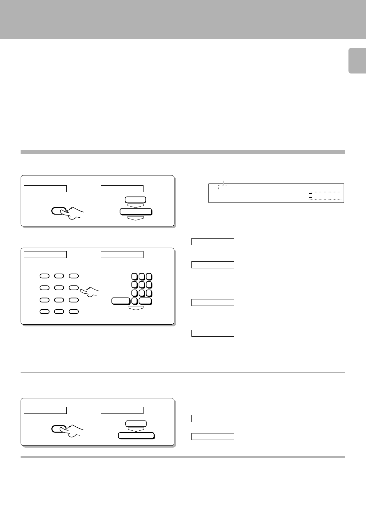
Playback from desired track
Let the “PGM” indicator go off.
1
Operate in stopped condition.
RC operation GRC operation
P.MODE
CHARACTER
PGM
ENTER
P.mode
ENTER
Playback of Mini Disc
DM-S500 (En)
“PGM“ goes off
SINGLE
0
01 0:00
÷ If the “PGM“ indicator is lit, press the P.MODE/CHARACTER key of
the remote control unit to turn it off.
L
∞
R
(−dB)
3
0130105
15
Select the desired track number.
2
RC operation GRC operation
A
ABC DEF
123
GHI JKL MNO
456
PRS TUV WXY
789
/
&
i j
+100 0 +10
f,FHI
QZ
1 2 3
4 5 6
7 8 9
0 +10+100
ENTER
RC operation
Press the numeric keys as shown below...
To enter track No. 23 : 0, 0, 3
GRC operation
Press the numeric keys as shown below...
To enter track No. 23 : 0, Enter, 0, Enter, 3, Enter
To listen from an intermediate position of a track:
RC operation
Listening from an intermediate position of the title being
played (.3)
: Press ),3 in this order.
GRC operation
Listening from an intermediate position of the title being
played (.3)
: Press ), Enter, 3, Enter, in this order.
Listening in random order (RANDOM playback)
As the title each time will be selected at random, you can listen for a long time without getting bored.
Operate in stopped condition.
RC operation GRC operation
RANDOM
Mode
ENTER
Random
To select a different title during listening :
RC operation
Press the ¢ key.
GRC operation
Return the previous menu and select the ¢ icon.
Disc recorded in monaural mode
This unit is capable of playing a disc recorded in the monaural mode.
As the amount of data required to record information in the monaural mode is half the amount required in the stereo mode,
the play (record) time of a disc recorded in the monaural mode is twice (max. 148 minutes) as that of a disc recorded in the stereo
mode.
16
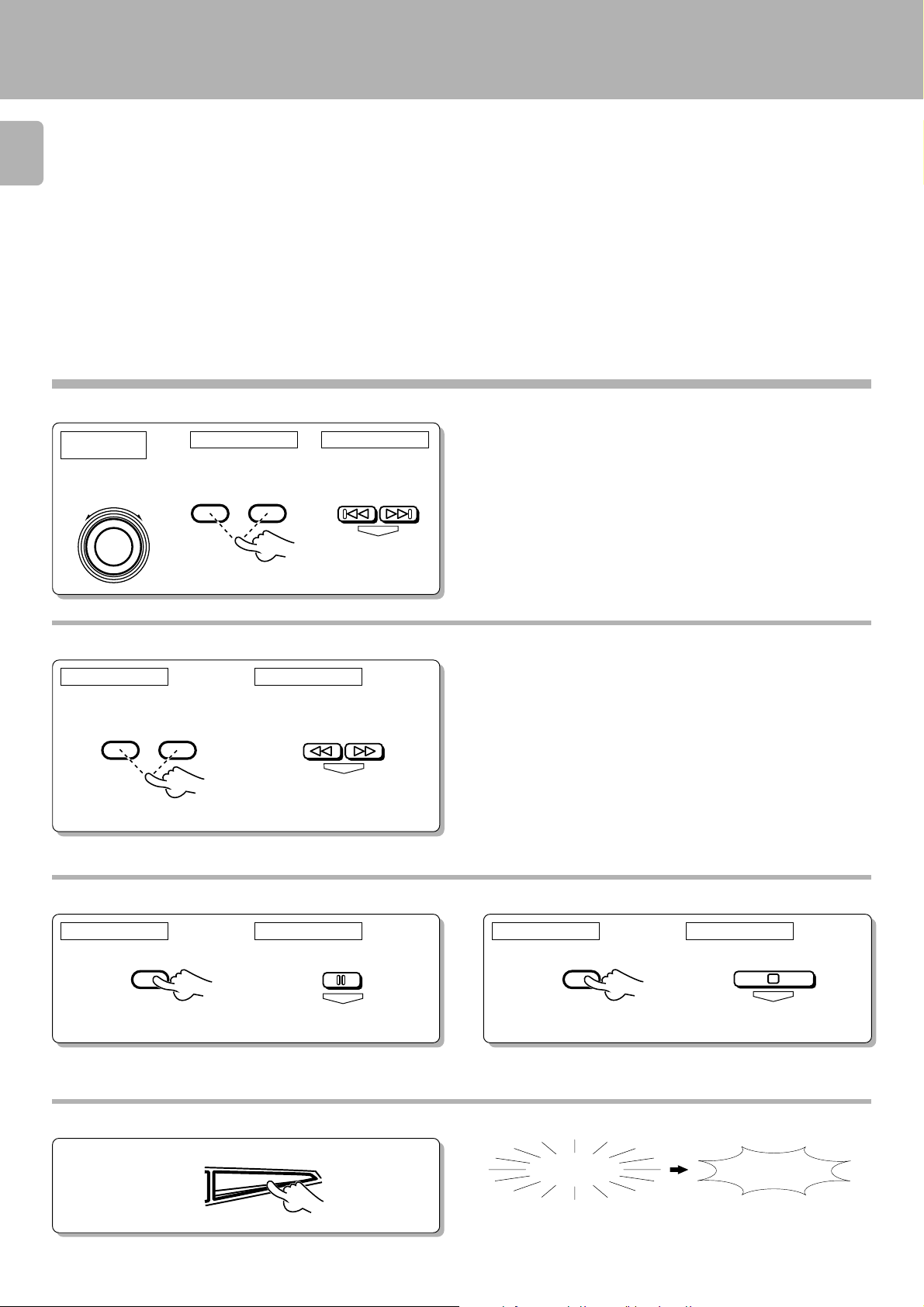
Skipping tracks
Playback of Mini Disc
DM-S500 (En)
Main unit
operation
To skip
backward
SHUTTLE
To skip
forward
¢4
RC operation GRC operation
To skip
4¢
To skip
backward
forward
Searching in a track
RC operation GRC operation
Forward
search
Reverse
search
Reverse
search
CURSOR/CHECK
1¡
To skip
backward
ENTER
ENTER
Forward
search
To skip
forward
÷ The track in the direction of the pressed button is skipped, and the
selected track will be played from the beginning.
÷ When the 4 key is pressed once during playback, the track being
played will be played from the beginning. (If it is pressed within 2
seconds from the start of a track, the previous track to the current track
will be played from the beginning.)
÷ Playback restarts from the position with which the key is released.
÷ If forward or reverse search is started during play-pause, the disc can
be searched at a high speed but sound is not output.
÷ When the reverse search is started during the program mode and the
beginning of the current track is attained, it will be played from the
beginning.
*
To pause playback
To stop playback
RC operation GRC operation RC operation GRC operation
8
ENTER
7
÷ Each press pauses and plays the MD alternately.
Ejecting the disc
E
Main unit
0
JECT
Mini Disc has been ejected.
N
ENTER
ODISC
 Loading...