

Page 1

2260B Series
www.keithley.com
Verification
Procedure
A Tektronix
Company
A
G R E A T E R M E A S U R E O F C O N F I D E N C E
Multi-Range
Programming
DC Power
Supplies
077-1048
-01/ A
u
g
u
s
t
2015
Page 2

Series 2260B
Multi-Range Programmable DC Power Supplies
VERIFICATION PROCEDURE
ISO-9001 CERTIFIED MANUFACTURER
Page 3

This manual contains proprietary information, which is protected by copyright. All rights are reserved.
No part of this manual may be photocopied, reproduced or translated to another language without
prior written consent of Keithley company.
The information in this manual was correct at the time of printing. However, Keithley continues to
improve products and reserves the rights to change specification, equipment, and maintenance
procedures at any time without notice.
Page 4

Table of Contents
1
Table of Contents
Preparing for Verification ....................................................... 2
List of Equipment for Verification ............................................ 3
Constant Voltage Tests .......................................................... 4
Voltage Programming and Measurement Accuracy .............................................. 4
CV Load Regulation ............................................................................................. 5
CV Line Regulation .............................................................................................. 6
CV Ripple and Noise ............................................................................................ 7
Transient Recovery Time ..................................................................................... 8
Constant Current Tests ........................................................ 10
Current Programming and Measurement Accuracy ............................................ 10
CC Load Regulation ........................................................................................... 11
CC Line Regulation ............................................................................................ 12
Verification Test Record Form ............................................... 13
30V ................................................................................................................... 13
80V ................................................................................................................... 15
250V ................................................................................................................. 17
800V ................................................................................................................. 19
Page 5

2260B Verification Procedure
2
Preparing for Verification
Note
In order to ensure performance accuracy, we recommend
you to verify all items listed in this chapter at once.
When to verify the
specification
When using the power supply in a new environment
After replacing one of the major internal modules, such
as front panel or power supply PCB
When you need to make sure that the power supply is
malfunctioning or not
Verification
Environment
Location: Indoor, no direct sunlight, dust free
Relative Humidity: < 80%
Temperature: +18~+28°C
Warm-up time: ≥ 30 minutes
When the
verification fails…
Calibrate the instrument when a corresponding
calibration item exists.
For other items, send the power supply back to the
factory for repair.
Page 6

List of Equipment for Verification
3
List of Equipment for Verification
Here is the list of all equipment used in the service operations.
Type
Specifications
Recommended Model
Digital Voltmeter
Resolution: 1 uV @ 1V
Keithley Model
2000 or equivalent
Readout: 6 1/2 digits
Current Shunt
3A (0.1Ω) 0.02%, TC=10ppm/℃
30A (0.01Ω) 0.02%, TC=10ppm/℃
300A (0.001Ω) 0.02%,
TC=10ppm/℃
Oscilloscope
Sensitivity: 1 mV
Bandwidth Limit: 20 MHz
Probe: 1:1 with JEITA RC-9131B
Tektronix
DPO4014B or
equivalent
AC Power Source
Adjustable to highest rated input
voltage range.
Power: 3000 VA
Ametek 3001i or
equivalent
Electronic Load
60V, 240A minimum, with transient
capability and a slew rate of 1A/us
or better.
Ametek SLH, SLM
or PLA series
electronic loads or
equivalent
500V, 60A minimum, with transient
capability and a slew rate of
0.4A/us or better
1000V, 12A minimum, with
transient capability and a slew rate
of 0.2A/us or better
Page 7
2260B Verification Procedure
4
Constant Voltage Tests
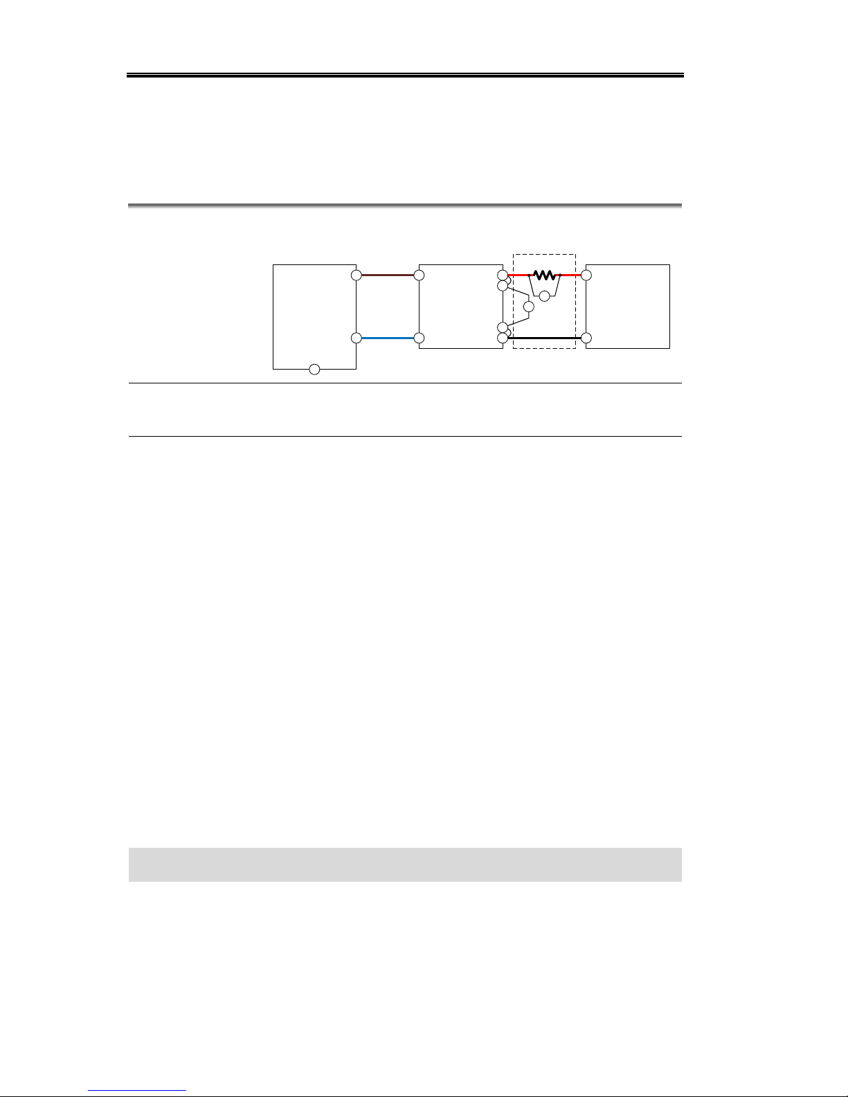
Voltage Programming and Measurement Accuracy
Connection
Fig. 1
L
N
G
AC Power Source
2260B
L
N
+
-
+
-
V
Precision
Current Shunt
A
+
-
+V
-V
+S
-S
Background
This test verifies that the voltage programming and
measurement functions are within specifications.
Procedure
1. Turn off the power supply and connect the DVM from
the PCS-1000 directly across the +S and -S terminals as
shown in the fig. 1 connection.
2. Turn on the power supply and program the output
voltage to zero and the output current to its maximum
programmable value (Imax) with the load off. The CV
indicator should be on and the output current reading
should be approximately zero.
3. Record the output voltage readings on the digital
voltmeter (DVM) and the voltage measured over the
interface. The readings should be within the limits
specified in the test record form for the appropriate
model under Voltage Programming and Measurement,
Minimum Voltage Vout.
4. Program the output voltage to its full-scale rating.
5. Record the output voltage readings on the DVM and
the voltage measured over the interface. The readings
should be within the limits specified in the test record
form for the appropriate model under Voltage
Programming and Measurement, Rated Voltage Vout.
Verifying Voltage Programming and Measurement Accuracy is complete
Page 8
Constant Voltage Tests
5
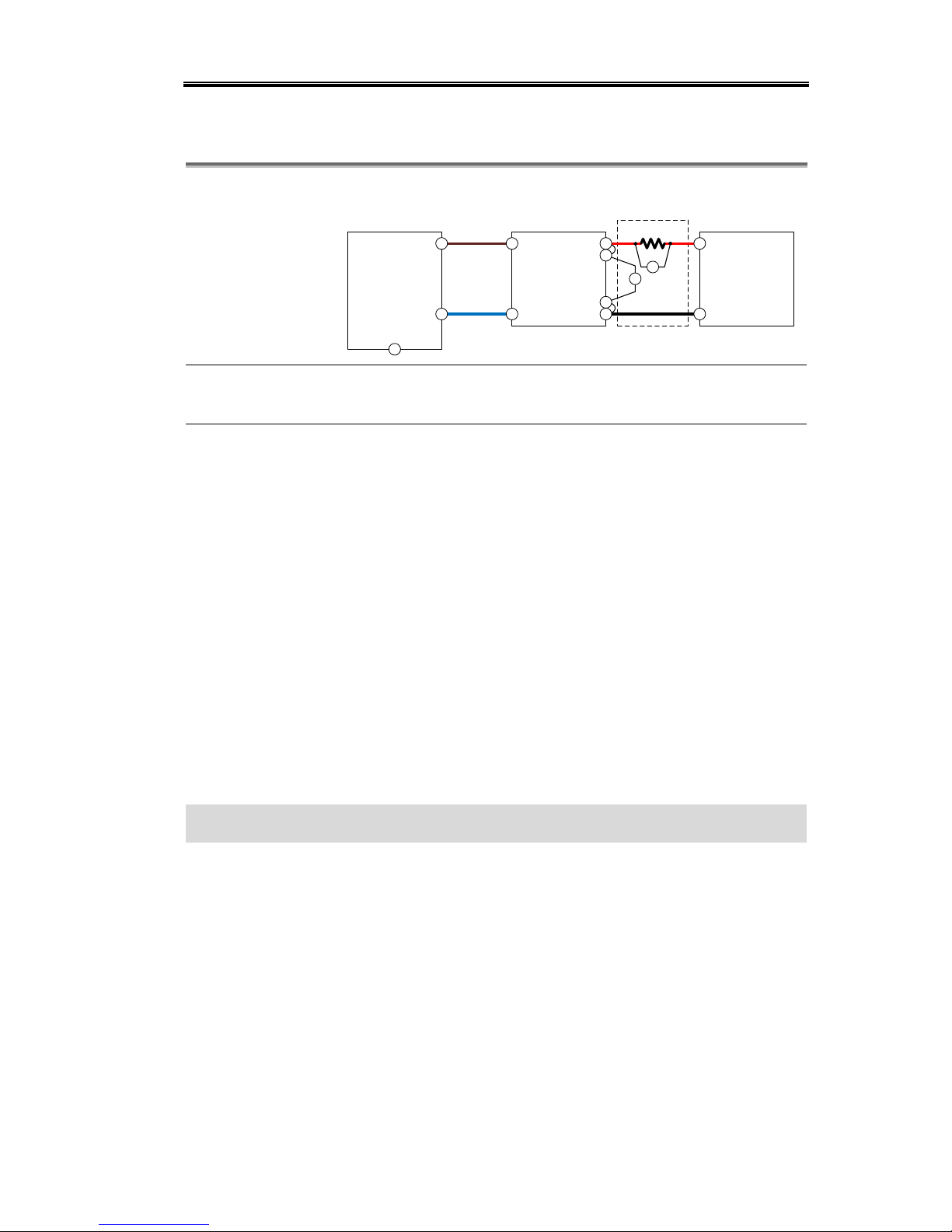
CV Load Regulation
Connection
Fig.2
L
N
G
AC Power Source
2260B
L
N
+
-
+
-
V
Electronic DC Load
Precision
Current Shunt
A
+
-
+V
-V
+S
-S
Background
This test measures the change in output voltage resulting
from a change in output current from full load to no load.
Procedure
1. Turn off the power supply and connect the DVM from
the PCS-1000 and an electronic load as shown in the fig.
2 connection.
2. Turn on the power supply and program the output
current to its maximum programmable value (Imax)
and the output voltage to its full scale value.
3. Set the electronic load for the output's full-scale
current. The CV indicator on the front panel must be
on. If it is not, adjust the load so that the output current
drops slightly.
4. Record the output voltage reading from the DVM.
5. Open the load and record the voltage reading from the
DVM again. The difference between the DVM readings
in steps 4 and 5 is the load effect, which should not
exceed the value listed in the test record form for the
appropriate model under CV Load Regulation.
Verifying CV Load Regulation is complete
Page 9

2260B Verification Procedure
6
CV Line Regulation
Connection
Fig. 3
L
N
G
AC Power Source
2260B
L
N
+
-
+
-
V
Electronic DC Load
Precision
Current Shunt
A
+
-
+V
-V
+S
-S
Background
This test measures the change in output voltage that
results from a change in AC line voltage from the
minimum to maximum value within the line voltage
specifications.
Procedure
1. Turn off the power supply and connect the ac power
source.
2. Connect the DVM from the PCS-1000 and an electronic
load as shown in the fig. 3 connection. Set the variable
ac voltage to nominal line voltage.
3. Turn on the power supply and program the output
current to its maximum programmable value (Imax)
and the output voltage to its full-scale value.
4. Set the electronic load for the output's full-scale
current. The CV indicator on the front panel must be
on. If it is not, adjust the load so that the output current
drops slightly.
5. Adjust the ac power source to the low-line voltage (85
VAC for 100/120 nominal line; 170 VAC for 200/240
nominal line).
6. Record the output voltage reading from the DVM.
7. Adjust the ac power source to the high-line voltage (132
VAC for 100/120 nominal line; 265 VAC for 200/240
nominal line).
8. Record the output voltage reading on the DVM. The
difference between the DVM reading in steps 5 and 7 is
the source effect, which should not exceed the value
listed in the test record form for the appropriate model
under CV Line Regulation.
Verifying CV Line Regulation is complete
Page 10

Constant Voltage Tests
7
CV Ripple and Noise
Connection
Fig. 4
L
N
G
AC Power Source
2260B
L
N
+
-
+
-
Electronic DC Load
+
-
50 Ohm
4700pF
Scope
BW: 20MHz
1:1 50 Ohm p robe
+V
-V
+S
-S
Connection
Fig. 5
L
N
G
AC Power Source
2260B
L
N
+
-
Electronic DC Load
Scope
BW: 10MHz
V
Low Pass Filter
BW: 1MHz
+
-
+
-
+V
-V
+S
-S
Background
Measure the DC output voltage with the (1:1) probe on.
Measurement frequency bandwidth is 10Hz to 20MHz for
peak to peak. Measurement frequency bandwidth is 5Hz
to 1MHz for rms.
Procedure
1. Turn off the power supply and connect the electronic
load (or load resistor), probe, and an oscilloscope (ac
coupled) to the output as shown in the fig. 4
connection.
2. Set the oscilloscope's bandwidth limit on 20 MHz, and
set the sampling mode.
3. Program the power supply to output current to its
maximum programmable value (Imax) and the output
voltage to its full-scale value and enable the output. Let
the oscilloscope run for a few seconds to generate
enough measurement points. The result should not
exceed the peak-to-peak limits the test record.
4. Use the oscilloscope to measure the RMS noise voltage
using the bandwidth shown in fig. 5. The result should
not exceed the rms limits in the test record form for the
appropriate model under CV Ripple and Noise - rms.
Page 11

2260B Verification Procedure
8
Verifying CV Ripple and Noise is complete
Transient Recovery Time
Background
This measures the time for the output voltage to recover to
within the specified value following a 50% to 100% change
in the load current.
Connection
Fig. 6
L
N
G
AC Power Source
2260B
L
N
+
-
+
-
Electronic DC Load
+
-
Scope
+V
-V
+S
-S
Procedure
1. Turn off the power supply and connect the output as in
the fig. 6 connection with the oscilloscope across the +S
and –S terminals.
2. Turn on the power supply and program the output
current to its maximum programmable value (Imax)
and the output voltage to its full-scale value.
3. Set the electronic load to operate in constant current
mode. Program its load current to 50% of the power
supply's full scale current value.
4. Set the electronic load's transient generator frequency
to 100 Hz and its duty cycle to 50%.
5. Program the load's transient current level to 100% of
the power supply's full-scale current value. Turn the
transient generator on.
6. Adjust the oscilloscope for a waveform similar to that
shown in the following fig. 7.
Fig. 7
t
v
v
t
50% to 100%
Load Transient
100% to 50%
Load Transient
Page 12

Constant Voltage Tests
9
7. The output voltage should return to within the
specified voltage in the specified time following the
50% to 100% load change. Check transients by
triggering on the positive and negative slope. Record
the voltage at time “t” in the performance test record
form under Transient Response.
Verifying Transient Recovery Time Regulation is complete
Page 13

2260B Verification Procedure
10
Constant Current Tests
Current Programming and Measurement Accuracy
Connection
Fig. 8
L
N
G
AC Power Source
2260B
L
N
+
-
+
-
V
Precision
Current Shunt
A
+
-
+V
-V
+S
-S
Background
This test verifies that the current programming and
measurement functions are within specifications.
Procedure
1. Turn off the power supply and connect the current
shunt directly across the output as shown in the fig. 8
connection.
2. Turn on the power supply and program the output
voltage to its full-scale value and the output current to
zero. The CC indicator should be on and the output
voltage reading should be approximately zero.
3. Record the output current readings on the precision
current shunt (PCS-1000) and the current measured
over the interface. The readings should be within the
limits specified in the test record form for the
appropriate model under Current Programming and
Measurement, Minimum Current Iout.
4. Program the output current to its full-scale rating.
5. Record the output current readings on the precision
current shunt (PCS-1000) and the voltage measured
over the interface. The readings should be within the
limits specified in the test record form for the
appropriate model under Current Programming and
Measurement, Rated Current Iout.
Verifying Current Programming and Measurement Accuracy is complete
Page 14

Constant Current Tests
11
CC Load Regulation
Connection
Fig. 9
L
N
G
AC Power Source
2260B
L
N
+
-
+
-
V
Electronic DC Load
Precision
Current Shunt
A
+
-
+V
-V
+S
-S
Background
This test measures the change in output current resulting
from a change in output voltage from full scale to short
circuit.
Procedure
1. Turn off the power supply and connect the precision
current shunt and electronic load as shown in the fig. 9
connection.
2. Turn on the power supply and program the output
current to its maximum programmable value (Imax)
and the output voltage to its full-scale value.
3. With the electronic load in CV mode, set it for the
output’s full scale voltage. The CC indicator on the
front panel must be on. If it is not, adjust the load so
that the voltage drops slightly.
4. Record the output current reading from the PCS-1000.
5. Short the electronic load. Record this value (Iout). The
difference in the current readings in steps 3 and 4 is the
load effect, which should not exceed the value listed in
the test record form for the appropriate model under
CC Load Regulation.
Verifying CC Load Regulation is complete
Page 15

2260B Verification Procedure
12
CC Line Regulation
Connection
Fig. 10
L
N
G
AC Power Source
2260B
L
N
+
-
+
-
V
Electronic DC Load
Precision
Current Shunt
A
+
-
+V
-V
+S
-S
Background
This test measures the change in output current that
results from a change in AC line voltage from the
minimum to maximum value within the line voltage
specifications.
Procedure
1. Turn off the power supply and connect the ac power
source..
2. Connect the current shunt and electronic load as shown
in the fig. 10 connection. Set the variable ac voltage to
nominal line voltage.
3. Turn on the power supply and program the output
current to its full-scale value and the output voltage to
its maximum programmable value (Vmax).
4. With the electronic load in CV mode, set it for the
output’s full scale voltage. The CC indicator on the
front panel must be on. If it is not, adjust the load so
that the voltage drops slightly.
5. Adjust the ac power source to the low-line voltage (85
VAC for 100/120 nominal line; 170 VAC for 200/240
nominal line).
6. Record the output current reading from the PCS-1000.
7. Adjust the ac power source to the high-line voltage (132
VAC for 100/120 nominal line; 265 VAC for 200/240
nominal line).
8. Record the output current reading on the PCS-1000.
The difference between the PCS-1000 reading in steps 5
and 7 is the source effect, which should not exceed the
value listed in the test record form for the appropriate
model under CC Line Regulation.
Verifying CC Line Regulation is complete
Page 16

Verification Test Record Form
13
Verification Test Record Form
Print out these pages and record the results. Keep it with the power supply.
30V
Model
2260B-30-36
2260B-30-72
2260B-30-108
Serial number
____________________
Date
Year___________
Month__________
Date___________
Verified by
Name____________________________
Company/Contact_________________________
Environment
Temperature______°C
Humidity______%
Constant Voltage Test
Model
Min. Specs.
Results
Max. Specs.
Voltage Programming and Measurement
Minimum Voltage V
out
All
- 10 mV
+ 10 mV
Measurement Accuracy
All
Vout - 10 mV
Vout + 10 mV
Rated Voltage Vout
All
29.960 V
30.040 V
Measurement Accuracy
All
Vout - 40 mV
Vout + 40 mV
CV Line Regulation
All
- 18 mV
+ 18 mV
CV Load Regulation
All
- 20 mV
+ 20 mV
CV Ripple and Noise
peak-to-peak
30-36
N/A
60 mV
30-72
N/A
80 mV
30-108
N/A
100 mV
rms
30-36
N/A
7 mV
30-72
N/A
11 mV
30-108
N/A
14 mV
Transient Response Time
Voltage @ 1ms
All
- 40 mV
+ 40 mV
Constant Current Test
Model
Min. Specs.
Results
Max. Specs.
Current Programming and Measurement
Minimum Current Iout
30-36
- 30 mA
+ 30 mA
30-72
- 60 mA
+ 60 mA
30-108
- 100 mA
+ 100 mA
Measurement Accuracy
30-36
Iout - 30 mA
Iout + 30 mA
30-72
Iout - 60 mA
Iout + 60 mA
Page 17

2260B Verification Procedure
14
30-108
Iout - 100 mA
Iout + 100 mA
Rated Current Iout
30-36
35.934 A
36.066 A
30-72
71.898 A
72.102 A
30-108
107.862 A
108.138 A
Measurement Accuracy
30-36
Iout - 66 mA
Iout + 66 mA
30-72
Iout - 102 mA
Iout + 102 mA
30-108
Iout - 138 mA
Iout + 138 mA
CC Line Regulation
30-36
- 41 mA
+ 41 mA
30-72
- 77 mA
+ 77 mA
30-108
- 108 mA
+ 108 mA
CC Load Regulation
30-36
- 41 mA
+ 41 mA
30-72
- 77 mA
+ 77 mA
30-108
- 108 mA
+ 108 mA
Page 18

Verification Test Record Form
15
80V
Model
2260B-80-13
2260B-80-27
2260B-80-40
Serial number
____________________
Date
Year___________
Month__________
Date___________
Verified by
Name____________________________
Company/Contact_________________________
Environment
Temperature______°C
Humidity______%
Constant Voltage Test
Model
Min. Specs.
Results
Max. Specs.
Voltage Programming and Measurement
Minimum Voltage V
out
All
- 10 mV
+ 10 mV
Measurement Accuracy
All
Vout - 10 mV
Vout + 10 mV
Rated Voltage Vout
All
79.910 V
80.090 V
Measurement Accuracy
All
Vout - 90 mV
Vout + 90 mV
CV Line Regulation
All
- 43 mV
+ 43 mV
CV Load Regulation
All
- 45 mV
+ 45 mV
CV Ripple and Noise
peak-to-peak
80-13
N/A
60 mV
80-27
N/A
80 mV
80-40
N/A
100 mV
rms
80-13
N/A
7 mV
80-27
N/A
11 mV
80-40
N/A
14 mV
Transient Response Time
Voltage @ 1ms
All
- 90 mV
+ 90 mV
Constant Current Test
Model
Min. Specs.
Results
Max. Specs.
Current Programming and Measurement
Minimum Current Iout
80-13
- 10 mA
+ 10 mA
80-27
- 30 mA
+ 30 mA
80-40
- 40 mA
+ 40 mA
Measurement Accuracy
80-13
Iout - 10 mA
Iout + 10 mA
80-27
Iout - 30 mA
Iout + 30 mA
80-40
Iout - 40 mA
Iout + 40 mA
Rated Current Iout
80-13
13.476 A
13.524 A
80-27
26.943 A
27.057 A
80-40
40.419 A
40.581 A
Page 19

2260B Verification Procedure
16
Measurement Accuracy
80-13
Iout - 24 mA
Iout + 24 mA
80-27
Iout - 57 mA
Iout + 57 mA
80-40
Iout - 81 mA
Iout + 81 mA
CC Line Regulation
80-13
- 18.5 mA
+ 18.5 mA
80-27
- 32 mA
+ 32 mA
80-40
- 45.5 mA
+ 45.5 mA
CC Load Regulation
80-13
- 18.5 mA
+ 18.5 mA
80-27
- 32 mA
+ 32 mA
80-40
- 45.5 mA
+ 45.5 mA
Page 20

Verification Test Record Form
17
250V
Model
2260B-250-4
2260B-250-9
2260B-250-13
Serial number
____________________
Date
Year___________
Month__________
Date___________
Verified by
Name____________________________
Company/Contact_________________________
Environment
Temperature______°C
Humidity______%
Constant Voltage Test
Model
Min. Specs.
Results
Max. Specs.
Voltage Programming and Measurement
Minimum Voltage V
out
All
- 200 mV
+ 200 mV
Measurement Accuracy
All
Vout - 200 mV
Vout + 200 mV
Rated Voltage Vout
All
249.55 V
250.45 V
Measurement Accuracy
All
Vout - 450 mV
Vout + 450 mV
CV Line Regulation
All
- 128 mV
+ 128 mV
CV Load Regulation
All
- 130 mV
+ 130 mV
CV Ripple and Noise
peak-to-peak
250-4
N/A
80 mV
250-9
N/A
100 mV
250-13
N/A
120 mV
rms
250-4
N/A
15 mV
250-9
N/A
15 mV
250-13
N/A
15 mV
Transient Response Time
Voltage @ 1ms
All
- 260 mV
+ 260 mV
Constant Current Test
Model
Min. Specs.
Results
Max. Specs.
Current Programming and Measurement
Minimum Current Iout
250-4
- 5 mA
+ 5 mA
250-9
- 10 mA
+ 10 mA
250-13
- 15 mA
+ 15 mA
Measurement Accuracy
250-4
Iout - 5 mA
Iout + 5 mA
250-9
Iout - 10 mA
Iout + 10 mA
250-13
Iout - 15 mA
Iout + 15 mA
Rated Current Iout
250-4
4.4905 A
4.5095 A
250-9
8.9810 A
9.0190 A
250-13
13.471 A
13.529 A
Page 21

2260B Verification Procedure
18
Measurement Accuracy
250-4
Iout - 9.5 mA
Iout + 9.5 mA
250-9
Iout - 19 mA
Iout + 19 mA
250-13
Iout - 29 mA
Iout + 29 mA
CC Line Regulation
250-4
- 9.5 mA
+ 9.5 mA
250-9
- 14 mA
+ 14 mA
250-13
- 18.5 mA
+ 18.5 mA
CC Load Regulation
250-4
- 9.5 mA
+ 9.5 mA
250-9
- 14 mA
+ 14 mA
250-13
- 18.5 mA
+ 18.5 mA
Page 22

Verification Test Record Form
19
800V
Model
2260B-800-1
2260B-800-2
2260B-800-4
Serial number
____________________
Date
Year___________
Month__________
Date___________
Verified by
Name____________________________
Company/Contact_________________________
Environment
Temperature______°C
Humidity______%
Constant Voltage Test
Model
Min. Specs.
Results
Max. Specs.
Voltage Programming and Measurement
Minimum Voltage V
out
All
- 400 mV
+ 400 mV
Measurement Accuracy
All
Vout - 400 mV
Vout + 400 mV
Rated Voltage Vout
All
798.8 V
201.2 V
Measurement Accuracy
All
Vout - 1.2 V
Vout + 1.2 V
CV Line Regulation
All
- 403 mV
+ 403 mV
CV Load Regulation
All
- 405 mV
+ 405 mV
CV Ripple and Noise
peak-to-peak
800-1
N/A
150 mV
800-2
N/A
200 mV
800-4
N/A
200 mV
rms
800-1
N/A
30 mV
800-2
N/A
30 mV
800-4
N/A
30 mV
Transient Response Time
Voltage @ 1ms
All
- 260 mV
+ 260 mV
Constant Current Test
Model
Min. Specs.
Results
Max. Specs.
Current Programming and Measurement
Minimum Current Iout
800-1
- 2 mA
+ 2 mA
800-2
- 4 mA
+ 4 mA
800-4
- 6 mA
+ 6 mA
Measurement Accuracy
800-1
Iout - 2 mA
Iout + 2 mA
800-2
Iout - 4 mA
Iout + 4 mA
800-4
Iout - 6 mA
Iout + 6 mA
Rated Current Iout
800-1
1.4365 A
1.4435 A
800-2
2.8731 A
2.8869 A
800-4
4.3096 A
4.3304 A
Page 23

2260B Verification Procedure
20
Measurement Accuracy
800-1
Iout - 3.5 mA
Iout + 3.5 mA
800-2
Iout - 6.9 mA
Iout + 6.9 mA
800-4
Iout - 10.4 mA
Iout + 10.4 mA
CC Line Regulation
800-1
- 6.44 mA
+ 6.44 mA
800-2
- 7.88 mA
+ 7.88 mA
800-4
- 9.32 mA
+ 9.32 mA
CC Load Regulation
800-1
- 6.44 mA
+ 6.44 mA
800-2
- 7.88 mA
+ 7.88 mA
800-4
- 9.32 mA
+ 9.32 mA
Page 24

Specifications are subject to change without notice.
All Keithley trademarks and trade names are the property of Keithley Instruments, Inc.
All other trademarks and trade names are the property of their respective companies.
A G R E A T E R M E A S U R E O F C O N F I D E N C E
Keithley Instruments, Inc.
Corporate Headquarters • 28775 Aurora Road • Cleveland, Ohio 44139 • 440-248-0400 • Fax: 440-248-6168 • 1-888-KEITHLEY • www.keithley.com
A Tektronix Company
 Loading...