

Page 1

Model 2231A-30-3
Triple-channel DC Power Supply
Reference Manual
077-1004-01 / September 2014
www.keithley.com
*P077100401*
077-1004-01
A Tektr onix Company
Page 2

Triple-Channel DC Power Supply
Model 2231A-30-3
Reference Manual
a
© 2014, Keithley Instruments.
Cleveland, Ohio, U.S.A.
All rights reserved.
Any unauthorized reproduction, photocopy, or use of the information herein, in whole or in part,
without the prior written approval of Keithley Instruments. is strictly prohibited.
All Keithley Instruments product names are trademarks or registered trademarks of Keithley
Instruments. Other brand names are trademarks or registered trademarks of their respective
holders.
Document number: 077100401 / September 2014
Page 3

Page 4

Safety precaut ions
The following safety precautions should be observed before using this product and any associated instrumentation. Although
some instruments and accessories would normally be used with nonhazardous voltages, there are situations where hazardous
conditions may be present.
This product is intended for use by qualified personnel who recognize shock hazards and are familiar with the safety precautions
required to avoid possible injury. Read and follow all installation, operation, and maintenance information carefully before using
the product. Refer to the user documentation for complete product specifications.
If the product is used in a manner not specified, the protection provided by the product warranty may be impaired.
The types of product users are:
Responsible body is the individual or group responsible for the use and maintenance of equipment, for ensuring that the
equipment is operated within its specifications and operating limits, and for ensuring that operators are adequately trained.
Operators use the product for its intended function. They must be trained in electrical safety procedures and proper use of the
instrument. They must be protected from electric shock and contact with hazardous live circuits.
Maintenance personnel perform routine procedures on the product to keep it operating properly, for example, setting the line
voltage or replacing consumable materials. Maintenance procedures are described in the user documentation. The procedures
explicitly state if the operator may perform them. Otherwise, they should be performed only by service personnel.
Service personnel are trained to work on live circuits, perform safe installations, and repair products. Only properly trained
service personnel may perform installation and service procedures.
Keithley Instruments products are designed for use with electrical signals that are measurement, control, and data I/O
connections, with low transient overvoltages, and must not be directly connected to mains voltage or to voltage sources with high
transient overvoltages. Measurement Category II (as referenced in IEC 60664) connections require protection for high transient
overvoltages often associated with local AC mains connections. Certain Keithley measuring instruments may be connected to
mains. These instruments will be marked as category II or higher.
Unless explicitly allowed in the specifications, operating manual, and instrument labels, do not connect any instrument to mains.
Exercise extreme caution when a shock hazard is present. Lethal voltage may be present on cable connector jacks or test
fixtures. The American National Standards Institute (ANSI) states that a shock hazard exists when voltage levels greater than
30 V RMS, 42.4 V peak, or 60 VDC are present. A good safety practice is to expect that hazardous voltage is present in any
unknown circuit before measuring.
Operators of this product must be protected from electric shock at all times. The responsible body must ensure that operators
are prevented access and/or insulated from every connection point. In some cases, connections must be exposed to potential
human contact. Product operators in these circumstances must be trained to protect themselves from the risk of electric shock. If
the circuit is capable of operating at or above 1000 V, no conductive part of the circuit may be exposed.
Do not connect switching cards directly to unlimited power circuits. They are intended to be used with impedance-limited
sources. NEVER connect switching cards directly to AC mains. When connecting sources to switching cards, install protective
devices to limit fault current and voltage to the card.
Before operating an instrument, ensure that the line cord is connected to a properly-grounded power receptacle. Inspect the
connecting cables, test leads, and jumpers for possible wear, cracks, or breaks before each use.
When installing equipment where access to the main power cord is restricted, such as rack mounting, a separate main input
power disconnect device must be provided in close proximity to the equipment and within easy reach of the operator.
For maximum safety, do not touch the product, test cables, or any other instruments while power is applied to the circuit under
test. ALWAYS remove power from the entire test system and discharge any capacitors before: connecting or disconnecting
cables or jumpers, installing or removing switching cards, or making internal changes, such as installing or removing jumpers.
Do not touch any object that could provide a current path to the common side of the circuit under test or power line (earth)
ground. Always make measurements with dry hands while standing on a dry, insulated surface capable of withstanding the
voltage being measured.
For safety, instruments and accessories must be used in accordance with the operating instructions. If the instruments or
accessories are used in a manner not specified in the operating instructions, the protection provided by the equipment may be
Page 5

impaired.
Do not exceed the maximum signal level s of the instru ment s and acc es sori es, as defi ned in the specifi cat ion s and operating
information, and as shown on the instrument or test fixture panels, or switching card.
When fuses are used in a product, replace with the same type and rating for continued protection against fire hazard.
Chassis connections must only be used as shield connections for measuring circuits, NOT as protective earth (safety ground)
connections.
If you are using a test fixture, keep the lid closed while power is applied to the device under test. Safe operation requires the use
of a lid interlock.
If a
The
user documentation in all cases where the symbol is mark ed on the instru ment .
The symbol on an instrument means caution, risk of electric shock. Use standard safety precautions to avoid personal
contact with these voltages.
The symbol on an instrument shows that the surface may be hot. Avoid personal contact to prevent burns.
The symbol indicates a connection terminal to the equipment frame.
If this
properly disposed of according to federal, state, and local laws.
The WARNING heading in the user documentation explains dangers that might result in personal injury or death. Always read
the associated information very carefully before performing the indicated procedure.
The CAUTION heading in the user documentation explains h az ards that coul d dama ge the instr ume nt. Such dam age may
invalidate the warranty.
Instrumentation and accessories shall not be connected to humans.
Before performing any maintenance, disconnect the line cord and all test cables.
To maintain protection from electric shock and fire, replacement components in mains circuits — including the pow er
transformer, test leads, and input jacks — must be purchased from Keithley Instruments. Standard fuses with applicable national
safety approvals may be used if the rating and type are the same. Other components that are not safety-related may be
purchased from other suppliers as long as they are equivalent to the original component (note that selected parts should be
purchased only through Keithley Instruments to maintain accuracy and functionality of the product). If you are unsure about the
applicability of a replacement component, call a Keithley Instruments office for information.
screw is present, connect it to protective earth (safety ground) using the wire recommended in the user documentation.
symbol on an instrument means caution, risk of danger. The user must refer to the operating instructions located in the
symbol is on a product, it indicates that mercury is present in the display lamp. Please note that the lamp must be
To clean an instrument, use a damp cloth or mild, water-based cleaner. Clean the exterior of the instrument only. Do not apply
cleaner directly to the instrument or allow liquids to enter or spill on the instrument. Products that consist of a circuit board with
no case or chassis (e.g., a data acquisition board for installation into a computer) should never require cleaning if handled
according to instructions. If the board becomes contaminated and operation is affected, the board should be returned to the
factory for proper cleaning/servicing.
Safety precaution revision as of January 2013.
Page 6

Table of Contents
Introduction .............................................................................................................. 1-1
Welcome .............................................................................................................................. 1-1
Extended warranty ............................................................................................................... 1-1
Contact information .............................................................................................................. 1-1
CD-ROM contents ................................................................................................................ 1-2
Key features ......................................................................................................................... 1-2
Standard accessories ........................................................................................................... 1-2
Optional accessories ............................................................................................................ 1-3
Available services ................................................................................................................ 1-3
General ratings ..................................................................................................................... 1-3
Quick reference ........................................................................................................ 2-1
Front-panel overview ............................................................................................................ 2-1
Rear panel overview ............................................................................................................ 2-2
Installing the system ............................................................................................................. 2-2
Dimensions ............................................................................................................................... 2-2
Adjust the carrying handle ......................................................................................................... 2-3
Power the instrument on or off .................................................................................................. 2-4
Self-test procedure ............................................................................................................... 2-6
Check the output .................................................................................................................. 2-7
Voltage output check ................................................................................................................. 2-7
Current output check ................................................................................................................. 2-8
What to do if the power supply does not turn on ................................................................. 2-8
General operation .................................................................................................... 3-1
Front-panel operation overview ........................................................................................... 3-1
Panel description .................................................................................................................. 3-2
Indicator description ............................................................................................................. 3-3
Basic settings ....................................................................................................................... 3-3
Set the voltage output or voltage limit for a specific channel ..................................................... 3-3
Set the current output or current limit for a specif ic channel ..................................................... 3-3
Save and recall the setups ........................................................................................................ 3-3
Menu description .................................................................................................................. 3-4
Default Set ................................................................................................................................ 3-4
Enable Channels ....................................................................................................................... 3-5
Protection Settings .................................................................................................................... 3-5
Track CH1/CH2 ......................................................................................................................... 3-6
Combine CH1+CH2 .................................................................................................................. 3-7
User Settings ............................................................................................................................. 3-9
System Info ............................................................................................................................. 3-10
Overtemperature protection (OTP) .................................................................................... 3-11
Page 7

Table of Contents Model 2231A-30-3 Triple-Channel DC Power Supply Reference Manual
Remote communication........................................................................................... 4-1
Communication interfac e ..................................................................................................... 4-1
2231A-001 communication connector ................................................................................. 4-1
SCPI command reference ........................................................................................ 5-1
Common commands ............................................................................................................ 5-2
*CLS .......................................................................................................................................... 5-2
*ESE ......................................................................................................................................... 5-2
*ESR? ....................................................................................................................................... 5-3
*IDN? ........................................................................................................................................ 5-3
*OPC ......................................................................................................................................... 5-3
*RST ......................................................................................................................................... 5-3
*SRE ......................................................................................................................................... 5-4
*STB? ........................................................................................................................................ 5-4
*TRG ......................................................................................................................................... 5-4
*SAV ......................................................................................................................................... 5-5
*RCL ......................................................................................................................................... 5-5
*TST? ........................................................................................................................................ 5-5
*WAI .......................................................................................................................................... 5-5
*PSC ......................................................................................................................................... 5-6
APPly subsystem ................................................................................................................. 5-6
[SOURce:]APPLy ...................................................................................................................... 5-6
[SOURce:]APPly:VOLTage[:LEVel][:IMMediate][:AMPLitude] .................................................. 5-6
[SOURce:]APPly:CURRent[:LEVel][:IMMediate][:AMPLitude] .................................................. 5-7
CALibration subsystem ........................................................................................................ 5-7
CALibration:SECure:[STATe] .................................................................................................... 5-7
CALibrate:VOLTage:LEVel ....................................................................................................... 5-7
CALibrate:VOLTage[:DATA] <numeric value>} ......................................................................... 5-8
CALibrate:CURRent:LEVel ....................................................................................................... 5-8
CALibrate:CURRent[:DATA] {<numeric value>} ..................................................................... 5-8
CALibration:SAVe ..................................................................................................................... 5-9
CALibration:INITital ................................................................................................................... 5-9
CALibrate:STRing ..................................................................................................................... 5-9
DISPlay subsystem .............................................................................................................. 5-9
DISPlay[:WINDow][:STATe] ...................................................................................................... 5-9
DISPlay[:WINDow]:TEXT[:DATA] ........................................................................................... 5-10
DISPlay[:WINDow]:TEXT:CLEar ............................................................................................. 5-10
INSTrument subsystem...................................................................................................... 5-10
INSTrument[:SELect] .............................................................................................................. 5-10
INSTrument:NSELect .............................................................................................................. 5-11
INSTrument:COMbine:SERies ................................................................................................ 5-11
INSTrument:COMbine:PARAllel .............................................................................................. 5-11
INSTrument:COMbine:TRACk ................................................................................................ 5-12
INSTrument:COMbine:OFF..................................................................................................... 5-12
INSTrument:COUPle[:TRIGger] .............................................................................................. 5-12
MEASure subsystem .......................................................................................................... 5-12
MEASure[:SCALar]:VOLTage[:DC]? ....................................................................................... 5-13
FETCh[:VOLTage][:DC]? ........................................................................................................ 5-13
MEASure[:SCALar]:CURRent[:DC]? ....................................................................................... 5-13
FETCh:CURRent[:DC]? .......................................................................................................... 5-13
MEASure[:SCALar]:POWer[:DC]? .......................................................................................... 5-13
FETCh:POWer[:DC]? .............................................................................................................. 5-13
Page 8

Model 2231A-30-3 Triple-Channel DC Power Supply Reference Manual Table of Contents
OUTPut subsystem ............................................................................................................ 5-14
OUTPut[:STATe][:ALL] ............................................................................................................ 5-14
CHANnel:OUTPut[:STATe] ..................................................................................................... 5-14
OUTPut:ENABle ...................................................................................................................... 5-14
OUTPut:TIMer[:STATe] ........................................................................................................... 5-15
OUTPut:TIMer:DELay ............................................................................................................. 5-15
OUTPut:TRACk[:STATe]......................................................................................................... 5-15
OUTPut:SERies[:STATe] ........................................................................................................ 5-16
OUTPut: PARallel [:STATe] .................................................................................................... 5-16
SYSTem subsystem ........................................................................................................... 5-17
SYSTem:ERRor? .................................................................................................................... 5-17
SYSTem:VERSion? ................................................................................................................ 5-17
SYSTem:REMote .................................................................................................................... 5-17
SYSTem:LOCal ....................................................................................................................... 5-17
SYSTem:RWLock ................................................................................................................... 5-18
SYSTem:MODUle? ................................................................................................................. 5-18
SYSTem:BEEPer .................................................................................................................... 5-18
STATus subsystem ............................................................................................................ 5-19
STATus:QUEStionable[:EVENt]? ............................................................................................ 5-19
STATus:QUEStionable:ENABle .............................................................................................. 5-19
STATus:QUEStionable:CONDition? ....................................................................................... 5-19
STATus:PRESet ..................................................................................................................... 5-20
STATus:QUEStionable:INSTrument[:EVENt]?........................................................................ 5-20
STATus:QUEStionable:INSTrument:ENABle .......................................................................... 5-20
STATus:QUEStionable:INSTrument:ISUMmary<x>[:EVENt]? ................................................ 5-20
STATus:QUEStionable:INSTrument:ISUMmary<X>:ENABle ................................................. 5-21
STATus:QUEStionable:INSTrument:ISUMmary<x>:CONDition? ........................................... 5-21
STATus:OPERation[:EVENt]? ................................................................................................. 5-21
STATus:OPERation:CONDition? ............................................................................................ 5-22
STATus:OPERation:ENABle ................................................................................................... 5-22
STATus:OPERation:INSTrument[:EVENt]? ............................................................................ 5-22
STATus:OPERation:INSTrument:ENABle .............................................................................. 5-23
STATus:OPERation:INSTrument:ISUMmary<x>[:EVENt]? .................................................... 5-23
STATus:OPERation:INSTrument:ISUMmary<x>:ENABle ....................................................... 5-23
STATus:OPERation:INSTrument:ISUMmary<x>:CONDition? ................................................ 5-23
SOURce subsystem ........................................................................................................... 5-24
[SOURce:]CHANnel:OUTPut[:STATe] .................................................................................... 5-24
[SOURce:]CURRent[:LEVel][:IMMediate][:AMPLitude] ........................................................... 5-24
[SOURce:]CURRent[:LEVel]:UP[:IMMediate][:AMPLitude] ..................................................... 5-24
[SOURce:]CURRent[:LEVel]:DOWN[:IMMediate][:AMPLitude] ............................................... 5-25
[SOURce:]CURRent[:LEVel][:IMMediate]:STEP[:INCRement]................................................ 5-25
[SOURce:]CURRent[:LEVel]:TRIGgered[:IMMediate][:INCRement] ....................................... 5-25
[SOURce:]VOLTage[:LEVel][:IMMediate][:AMPLitude] ........................................................... 5-26
[SOURce:]VOLTage[:LEVel]:UP[:IMMediate][:AMPLitude] ..................................................... 5-26
[SOURce:]VOLTage[:LEVel]:DOWN[:IMMediate][:AMPLitude] ............................................... 5-26
[SOURce:]VOLTage[:LEVel][:IMMediate]:STEP[:INCRement]................................................ 5-27
[SOURce:]VOLTage[:LEVel]:TRIGgered[:IMMediate][:INCRement] ....................................... 5-27
[SOURce:]VOLTage:LIMIT[:LEVel] ......................................................................................... 5-27
[SOURce:]VOLTage:LIMit:STATe ........................................................................................... 5-28
Status model ...................................................................................................................... 5-29
Error messages .................................................................................................................. 5-31
Additional Information ............................................................................................. 6-1
Additional Model 2231A-30-3 information ............................................................................ 6-1
Page 9

Table of Contents Model 2231A-30-3 Triple-Channel DC Power Supply Reference Manual
Maintenance ............................................................................................................. A-1
Introduction .......................................................................................................................... A-1
Line fuse replacement .......................................................................................................... A-1
Cleaning the front-panel display .......................................................................................... A-2
Page 10

General ratings ......................................................................... 1-3
Welcome
Thank you for using a Keithley Instruments product. The Model 2231A-30-3 Trip-Channel
Programmable DC Power Supply is a flexible DC source designed to power a wide range of
applications. It offers three independent and isolated power channels, allowing you to power circuits
with different references or polarities. Each channel can be enabled or disabled as your application
requires. Basic current accuracy is 0.2% for all channels and linear regulation delivers low noise –
less than 5 mV
and the DB9 interface connector makes it easy to build PC-based systems. This compact power
supply covers a wide range of applications without covering a lot of bench space.
In this section:
Welcome .................................................................................. 1-1
Extended warranty.................................................................... 1-1
Contact information .................................................................. 1-1
CD-ROM contents .................................................................... 1-2
Button features ......................................................................... 1-2
Standard accessories ............................................................... 1-2
Optional accessories ................................................................ 1-3
Available services ..................................................................... 1-3
. Flexible display modes make it easy to use the two 30 V outputs in combination,
pp
Section 1
Introduction
Extended warranty
Additional years of warranty coverage are available on many products. These valuable contracts
protect you from unbudgeted service expenses and provide additional years of protection at a fraction
of the price of a repair. Extended warranties are available on new and existing products. Contact your
local Keithley Instruments office, sales partner, or distributor for details.
Contact information
If you have any questions a fter you review the information in this documentation, pleas e contac t your
local Keithley Instruments office, sales partner, or distributor, or call Keithley Instruments corporate
headquarters (toll-free inside the U.S. and Canada only) at 1-888-KEITHLEY (1-888-534-8453), or
from outside the U.S. at +1-440-248-0400. For worldwide contact numbers, visit the
Instruments website (http://www.keithley.com).
Keithley
Page 11

Section 1:Introduction Model 2231A Triple-channel DC Power Supply Reference Manual
CD-ROM contents
The Model 2231A-30-3 Product Information CD-ROM is shippe d with each power supply.
The Product Information CD-ROM contains:
• Reference Manual: Includes basic operation topics and maintenance information.
• Performance Verification: Contains performance verific ation proc edures . Ad dit ional test
equipment is required to complete the verification procedures.
• Accessories information: Documentation for accessories that are available for the Model
2231A-30-3.
For the latest drivers and additional support information, see the Keithley Instruments website
(http://www.keithley.com).
Key features
The Model 2231A-30-3 has the following features:
Three isolated output channels, including two 30 V at 3 A channels and one 5 V at 3 A channel
0.06% basic voltage accuracy
0.2% basic current accuracy
Less than 5 mVpp ripple and noise
Intelligent fan control, energy conservation and noise reduction
Overvoltage and overtemper atur e protec ti on
Standard accessories
Accessory Part number
Documentation CD 077102700
Calibration report 001165500
You will also get one of the following power cords:
Option Description
Option A0 North America and South America. The factory sets the line-voltage selector switch to 110 V.
Option A1 Universal Euro. The factory sets the line-voltage selector switch to 220 V.
Option A2 United Kingdom. The factory sets the line-voltage selector switch to 220 V.
Option A3 Australia. The factory sets the line-voltage selector switch to 220 V
Option A4 Chile, Italy. The factory sets the line-voltage selector switch to 220 V.
Option A5 Switzerland. The factory sets the line-voltage selector switch to 220 V.
Option A7 Israel. The factory sets the line-voltage selector switch to 220 V.
Option A8 Argentina. The factory sets the line-voltage selector switch to 220 V.
Option A9 China. The factory sets the line-voltage selector switch to 220 V.
Option A10 India. The factory sets the line-voltage selector switch to 220 V.
Option A11 India. The factory sets the line-voltage sel ect or switch to 220 V.
Option A13 Macao, Pakistan, Africa. The factory sets the line-voltage selector switch to 220 V.
1-2 077100401/September 2014
Page 12
Model 2231A-30-3 Triple-channel DC power supply Reference Manual Section1:Introduction
Optional accessories
Optional accessory Model number
USB communication adapter 2231A-001
Available services
For the current list of available services and accessor ies, upgra des, and opt ions for your instrument,
visit the Keithley Instruments website (http://www.keithley.com
Service Model Number
3-year factory warranty extended to 5 years from date of shipment 2231A-30-3-5Y-EW
3-year factory warranty extended to 1 additional year from date of
shipment
General ratings
The Model 2231A-30-3 instrument's general ratings and connections are listed in the following table.
When the mains power supplied to the Model 2231A-30-3 exceeds 253 V, the maximum operating
time at maximum output power is 1 hour. At the supply voltage range of 110 V, when the mains
power exceeds 132 V, the maximum operating time at maximum output power is 1 hour.
Category Specification
Supply voltage range
Environmental conditions For indoor use only
).
2230A-30-3-EW
• 110: 110 V-120 V
• 220: 220 V-230 V
Each range capable of +/-10% tolerance, 47 to 63 Hz.
Selectable by the line-voltage selector switch in the rear panel.
Operating: 0 °C to 40 °C (32 °F to 104 °F), 5% to 80% relative humidity
at up to 40 °C (104 °F)
Storage: −20 °C to 70 °C (-4 °F to 158 °F)
5% to 80% relative humidity at up to +40°C (104 °F) and 5% to 60%
relative humidity above +40°C (104°F) up to +70°C (158°F)
Pollution degree: 2
077100401/September 2014 1-3
Page 13

Page 14
In this section:
Front-panel overview ................................................................ 2-1
Rear panel overview ................................................................. 2-2
Installing the system ................................................................. 2-2
Self-test procedure ................................................................... 2-6
Check the output ...................................................................... 2-7
What to do if the power supply does not turn on ....................... 2-8
Front-panel overview
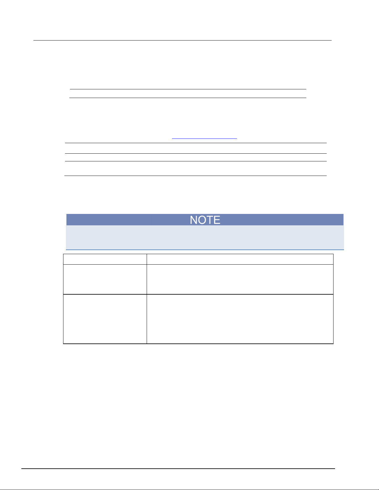
The front panel of Model 2231A-30-3 is shown below. Descriptions of the controls on the front
panel follow the figure.
Section 2
Quick reference
Figure 1: Model 2231A-30-3 front panel
Item Description
1 Vacuum fluorescent display (VFD)
2 Rotary knob
3 POWER button
4 Function buttons: Channel select buttons, V-Set (voltage setting), I-Set
(current setting), Menu and Output On/OFF
5 Numeric buttons and ESC button
6 Up/Down/Left/Right arrow buttons, Enter button and Save/Recall function
buttons
7 Output terminals
Page 15
Section 2:Quick reference Model 2231A Triple-channel DC Power Supply Reference Manual
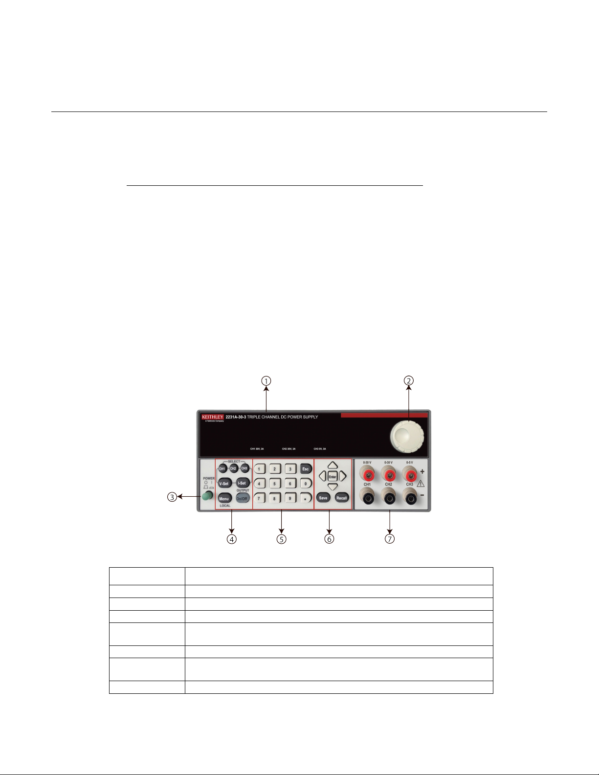
Rear panel overview
The rear panel of the Model 2231A-30-3 is shown below; descriptions follow the figure.
Figure 2: Model 2231A-30-3 rear panel
Item Description
1 Ventilation holes
2 TTL interface connector for remote control
3 110 V/220 V AC power selection switch
4 Fuse compartment
5 AC power inlet
Installing the system
This section contains information on how to install your Model 2231A-30-3 power supply.
• Unpack the instrument and check that you received all the items listed as standard
accessories.
• Check that you also received any other accessories that you ordered with your instr um ent.
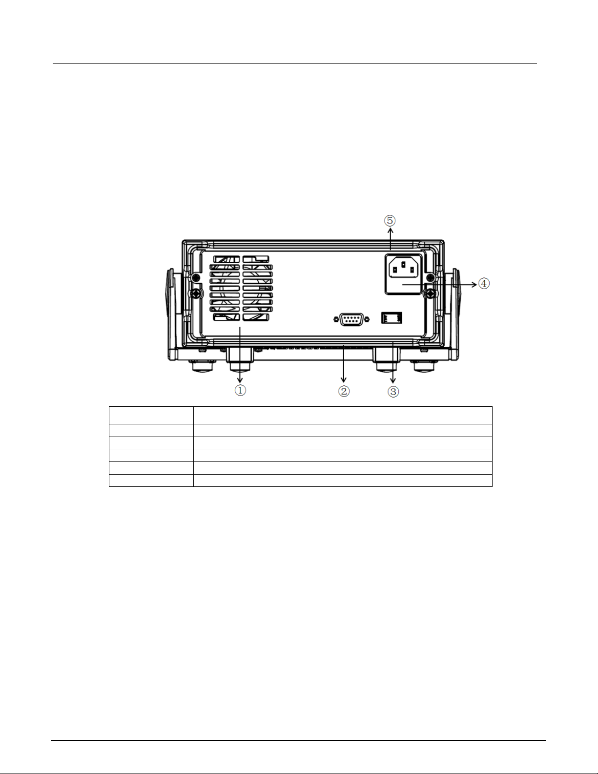
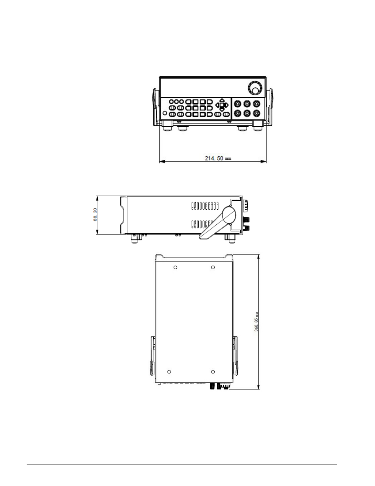
Dimensions
The dimensions of the Model 2231A-30-3 power supply: 214.5 mm wide × 88.2 mm high ×354.6
mm deep.
2-2 077100401/September 2014
Page 16
Model 2231A-30-3 Triple-channel DC Power Supply Reference Manual Section 2:Quick reference
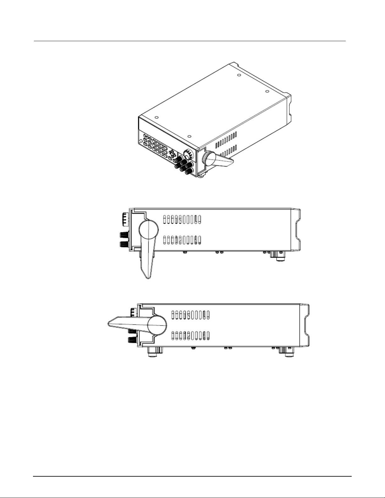
Figure 3: Model 2231A front and rear panel dimensions
Figure 4: Model 2231A-30-3 top and side dimensions
Adjust the carrying handle
The handle can be adjusted to the position shown in the following figures.
Figure 5: Place the instrument with the handle under the bottom surface
077100401/September 2014 2-3
Page 17
Section 2:Quick reference Model 2231A Triple-channel DC Power Supply Reference Manual
Figure 6: Place the instrument stand ing on the handle
Figure 7: Adjust the handle in front of the front panel
Power the instrument on or off
Follow the procedure below to connect the Model 2231A-30-3 to line power and turn on the
instrument. The Model 2231A-30-3 operates on two ranges: 110 V and 230 V at a frequency of
50 Hz or 60 Hz. You need to select the line voltage and frequency on the rear panel. Make sure
the line voltage setting is compatible with the line voltage in your area.
The Model 2231A-30-3 must be turned on and allowed to warm up for at least one hour to
achieve rated accuracies.
2-4 077100401/September 2014
Page 18
Model 2231A-30-3 Triple-channel DC Power Supply Reference Manual Section 2:Quick reference
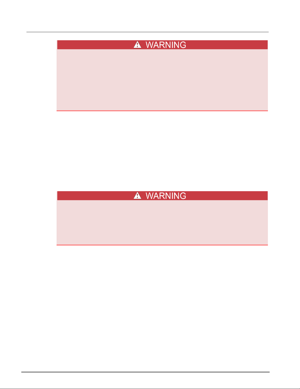
The power cord supplied with the Model 2231A contains a separate protective earth
(safety ground) wire for use with grounded outlets. When proper connections are made,
the instrument chassis is connected to power-line ground through the ground wire in the
power cord. In addition, a redundant protective earth connection is provided through a
screw on the rear panel. This terminal should be connected to a known protective earth.
In the event of a failure, not using a properly grounded protective earth and grounded
outlet may result in personal injury or death due to electric shock.
Do not replace detachable mains supply cords with inadequately rated cords. Failure to
use properly rated cords may result in personal injury or death due to electric shock.
To connect the power cord:
1. Make sure that the front panel POWER switch is in the off position.
2. Properly set the 110 V/220 V selector switch located on the rear panel.
3. Connect the female end of the supplied power cord to the AC receptacle on the rear panel.
4. Connect the other end of the power cord to a grounded AC outlet.
To turn a Model 2231A-30-3 on and off:
1. Disconnect any devices under test (DUTs) from the Model 2231A-30-3 before turning the
instrument on.
2. To turn your instrument on, push the front-panel POWER switch to place it in the on position.
The screen is displayed when power up is complete.
3. To turn your instrument off, Push the front-panel POWER switch to place it in the off position.
To avoid any fire or electric shock, please ensure the AC input voltage fluctuation does
not exceed 10% of the working voltage range.
To satisfy safety requirements, always use load wires heavy enough that they will not
overheat when carrying the maximum short-circuit output current of the power supply. If
there is more than one load, then every pair of load wires must be capable of safely
carrying the full-rated current of the power supply.
077100401/September 2014 2-5
Page 19

Section 2:Quick reference Model 2231A Triple-channel DC Power Supply Reference Manual
Self-test procedure
After the instrument is powered on, the screen displays the following information during
the self-test process.
Initializing…
After 1 s, the screen displays the following information for about 2 s if the EEPROM test
fails.
EEPROM Test Failure
If the last saved settings for the power supply are lost, the vacuum fluorescent display
displays the following information for 2 seconds:
User Data Lost
During the channel scan, the screen displays the following inform ation:
Scan Channels
If the channel data initialization fails, the screen displays the following information for 2
seconds:
Channel Initialization Failed
If the user calibration data in the EEPROM are lost, th e screen displays the following
information for 2 seconds:
Calibration Data Lost
2-6 077100401/September 2014
Page 20

Model 2231A-30-3 Triple-channel DC Power Supply Reference Manual Section 2:Quick reference
If the factory calibration data are lost, the screen displays the following information for 2
seconds:
Factory Calibration Data Lost
If no error occurs during the self-test, the screen should display as below: the first row is the
output voltage of the 3 channels, and the second row is the current or the OFF status
indicator.
10.00 V 11.00 V 3.00 V
0.000 A 0.000 A 0.000 A
Check the output
The following procedures verify that the power sup ply outputs its rated voltage and current and
properly responds to operations from the front panel.
Voltage output check
To verify basic voltage function without a load, please follow these steps:
1. Remove all leads from the output connectors.
2. Turn on the power supply.
3. Push Menu. Default Set should appear on the display.
4. Push Enter to bring up the default settings menu. No and Yes should appear on the display.
5. Push the down arrow keys to select Yes. Push Enter to enable the default settings.
6. Push the front-panel On/Off button to turn on the outputs. The OFF messages on the display
should be replaced by current readings and the CV indicators should turn on. The upper line
of the display should show the actual output voltage.
7. Check that the front-panel voltmeter properly responds to the number buttons. First, select a
channel using one of the channel select buttons. Push V-set, use the number buttons to set
the voltage value to 0 and push Enter. Check if the displayed voltage value is approximately
0 V and check if the displayed current value is approximately 0 A. You can confirm the 0 V
setting with a voltmeter.
8. Push V-set and use the numeric buttons and Enter button to set the voltage value to the
maximum allowable for your power supply, as indicate d on the unit's front-panel.
9. Check if the displayed voltage value is approximately the same value as the voltage setting.
10. Repeat steps 7 through 9 for each output channel.
077100401/September 2014 2-7
Page 21

Section 2:Quick reference Model 2231A Triple-channel DC Power Supply Reference Manual
Current output check
To verify the basic current functions when the power supply is short-circuited, please follow these
steps:
1. Remove all leads from the output connectors.
2. Turn on the power supply.
3. Push Menu. Default Set should appear on the display.
4. Push Enter to bring up the default settings menu. No and Yes should appear on the display.
5. Push the down arrow keys to select Yes. Push Enter to enable the default settings.
6. Ensure that the output is disabled and the OFF indicator is shown for all channels. If needed,
push the On/Off button to ensure that the outputs are disabled and the OFF messages are
displayed.
7. Use an insulated test lead to connect a short across the (+) and (-) output terminals of the
channel you will be testing.
Use a wire size sufficient to handle the maximum current.
To satisfy safety requirements, always use load wires heavy enough that they will not
overheat when carrying the maximum short-circuit output current of the power supply. If
there is more than one load, then every pair of load wires must be capable of safely
carrying the full-rated current of the power supply.
8. Push the On/Off button to enable the outputs. T he CC indicator should be on the channel
with the shorted output.
9. Select a channel using one of the channel select buttons.
10. Push I-set and use the numeric buttons and the Enter button to set the curre nt v alu e to 0 A.
Check if the displayed current value is approximately 0 A.
11. Push I-set and use the numeric buttons and the Enter button to set the curre nt valu e to the
maximum allowable for the output channel. Check if the displayed current value is
approximately the same value as the maximum allowable.
12. Turn all outputs off by pushing the Output On/Off button. Note that the outputs are off when
the display for all c han nels s ho ws <OFF>.
13. Repeat steps 7 through 12 for each output channel.
14. Turn off the instrument and remove the short wire from the (+) and (-) output terminals.
What to do if the power supply does not turn on
To solve problems you might encounter when turn ing on the power supply, please follow
these steps:
1. Verify that there is AC power applied to the power supply.
First, check that the AC power cord is firmly plugged in to the power connector on the rear-panel
of the power supply. You should also make sure that the AC power source you plugged the
power supply in to is energized. Then, check that the power supply is turned on.
2. Verify the power-line voltage setting.
2-8 077100401/September 2014
Page 22

Model 2231A-30-3 Triple-channel DC Power Supply Reference Manual Section 2:Quick reference
Make sure the voltage selector switch is set according to the present line voltage (110 VAC or
220 VAC) when the power supply is shipped from the factory. Change the voltage setting if it is
incorrect.
3. Verify the correct power-line fuse is installed.
If the fuse is damaged, please see the table below to replace the fuse for your power supply.
Model Fuse Specifications
2231A-30-3
3.15 A (220V AC)
6.30 A (110V AC)
4. If you need more help, contact Keithley.
077100401/September 2014 2-9
Page 23

Page 24

In this section:
Front-panel operation overview ................................................ 3-1
Panel description ...................................................................... 3-2
Indicator description ................................................................. 3-3
Basic settings ........................................................................... 3-3
Menu description ...................................................................... 3-4
Overtemperature protection ................................................... 3-11
Front-panel operation overview
Within a few seconds after powering on, the power supply shows the actual voltage for each channel
on the top line of the display and the actual current for each channel on the bottom line of the display.
Section 3
General operation
You can enable or disable the output of the power supply from the front-panel by pushing the output
On/Off button. When the output is off, the OFF message will appear on the disp la y.
The display shows the present operating status of each channel with display messages. When a
channel operates in constant voltage mode, the CV indicator is displayed. When it operates in the
constant current mode, the CC indicator is displayed.
To cancel a function operation (V-set, I-set, Save, Recall, or Menu), push the Esc button.
If the front-panel was locked with a password, enter the correct password after you push the function
buttons (V-set, I-set, Save, Recall, or Menu), then you can change the settings.
Page 25
Section 3: General operation Model 2231A Triple-channel DC Power Supply Reference Manual
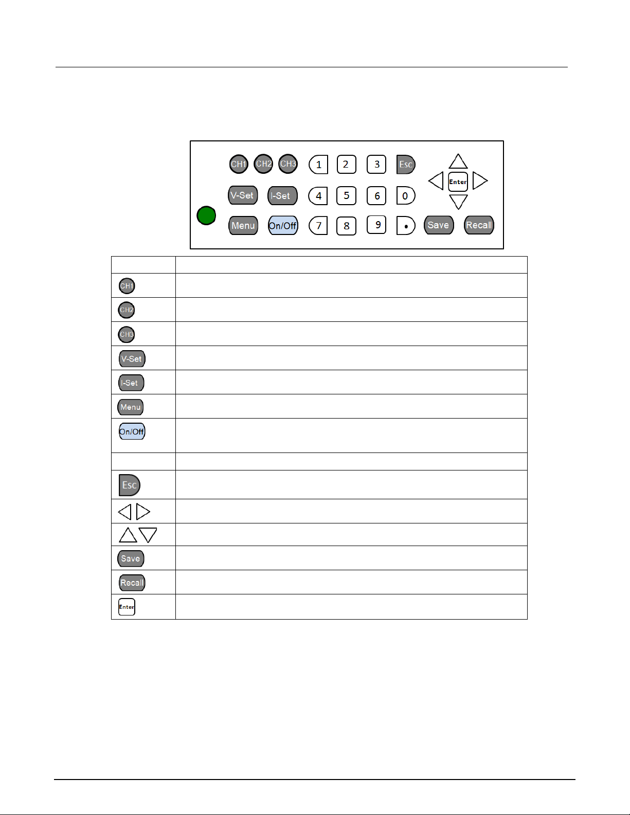
Panel description
Figure 8: Keyboard
Item Description
Select channel 1
Select channel 2
Select channel 3
Set the voltage limit
Set the current limit
Open the menu
Turn on or off all enabled channels. You can enable or disable each using the
0 to 9
menu. When turning on the output, the CC or CV indicator is displayed on the
screen. When turning off the output, OFF indic ator is displayed on the screen.
Numeric buttons
Return to previous menu level
Use left/right arrow buttons to move the cursor
Use up/down arrow keys to adjust the parameters or select the menu operation.
Save the present instrument settings as a user-saved setup. The Model
3-2 077100401/September 2014
2231A-30-3 supports up to 30 setups.
Return the instrument to the specified setup.
Select the menu item or confirm the cooperation.
Page 26

Model 2231A Triple-channel DC Power Supply Reference Manual Section 3: General operati on
CV
Indicator description
Item Description
CC
Series
Para
T
Constant current mode.
Constant voltage mode.
The power supply is in remote control mode.
The outputs of Channel 1 and channel 2 are wired in series.
The outputs of Channel 1 and channel 2 are wired in parallel.
Channel 1 and channel 2 are in tracking mode.
Basic settings
Set the voltage output or voltage limit for a specific channel
You may set the voltage limit from 0 V to the maximum voltage rating shown on the instrument
nameplate. To set the voltage limit, do the following:
1. The position of the cursor determines which channel will be adjusted. If the cursor is not located
on the correct channel, select the correct channel by pushing the appropriate channel select
button.
2. Push V-set.
3. Use the numeric buttons and push Enter to set the voltage limit. You can also use the up, down,
right and left arrow buttons.
Set the current output or curre nt li mi t f or a specific channel
You may set the current limit from 0 A to the maximum current value of each model. The maximum
current rating is shown on the instrument nameplate. To set the current limit, do the following:
1. The position of the cursor determines which channel will be adjusted. If the cursor is not located
in the correct channel, select the correct channel by pushing the appropriate channel select
button.
2. Push I-set.
3. Use the numeric buttons and push Enter to set the current limit. You can also use the up, down,
right and left arrow buttons.
Save and recall the setups
You can store up to 30 different setups in memory locations. Each setup includes a voltage limit,
current limit and maximum output voltage.
To save the setups:
1. After you set up the power supply, push the Save button.
2. Use the number buttons or the arrow buttons to select the setup memory (1 to 30) that you want
to store the values in.
3. Push Enter to confirm the memory location.
To recall the setups:
1. Push Recall.
077100401/September 2014 3-3
Page 27

Section 3: General operation Model 2231A Triple-channel DC Power Supply Reference Manual
Default Set
2. Use the number buttons or the arrow buttons to select the setup memory that you want to recall
from.
3. Push Enter.
You can also use the following SCPI command to save or recall the setup:
• *SAV
• *RCL
Model 2231A-30-3 does not support the save/recall function when channel 1 and channel 2 are
wired in series or parallel. Also, if channel 1 and channel 2 are in tracking mode, you cannot save or
recall the setup.
Menu description
Push the Menu button to enter menu operation. The organization of the menu is shown in the table
below.
Menu items Description
Enable Channels
Protection Settings
Max Volt Set
Track CH1/CH2
Combine CH1+CH2
User Settings
System Info
Output Timers
Key Lock
Output Recall The output status after power on
Save Last The voltage, current and max voltage set after pow er on
Key Beep Turn the button beeper on or off
Knob Lock Lock the knob
Baud Rate Check the baud rate (9600bps)
Error Log List all errors that occurred
Main:1.02/Aux:0.01 The firmware version
Calibrate Date 2014-04-28 16:06:58
Restore the factory default settings
Enable or disable output channels
Set the maximum voltage that can be set. This influences
the voltage setting range.
Set the output timers for each channel. Once the timer
expires, the output of the specified channel is turned off.
Lock the front panel with a password to avoid any improper
operation
Enable or disable the tracking mode
Combine the meter readings of channel 1 and channel 2.
Default Set
You can restore the factory default settings by doing the following:
1. Remove all of the leads from the output terminals.
2. Push the Power button to turn on the power supply.
3. Push Menu.
4. Push Enter to select Default Set.
5. Push the down arrow button to select Yes.
3-4 077100401/September 2014
Page 28

Model 2231A Triple-channel DC Power Supply Reference Manual Section 3: General operati on
Output Recall
6. Push Enter.
The default settings for the menu selections are as shown below.
Item
Enable Channels
Max V CH1
Max V CH2
Max V CH3
Timer CH1
Timer CH2
Timer CH3
Track CH1/CH2
Combine CH1+CH2
Save Last
Button beep
Knob Lock
Description
Enable CH1
Enable CH2
Enable CH3
Off
Off
Off
Off
Off
Off
Track Off
Combine Off
Off
On
Off
Off
Enable Channels
You can enable or disable each output channel using the menu settings. If a channel is disabled, it will
remain off after the Output On/Off button is turned on. The default setting is to have all channels
enabled.
Protection Settings
The protection settings allow you to set the max voltage, the output timers and the front panel button
lock for all of the channels.
Set the maximum voltage
This control determines the maximum voltage that you can set using the V-set control. This can help
prevent accidental overvoltage from being applied to sensitive loads.
To set the maximum voltage, follow these steps:
1. Push Menu.
2. Push the down a rrow button to select Protection Settings.
3. Push Enter. Max Volt Set should appear on the display.
4. Push Enter. A list of Max V settings for each channel will appear.
5. Use the up and down arrow keys to select the correct channel and push Enter to confirm.
6. Push the down arrow button to select On.
7. Use the numeric buttons or the up/down buttons or the rotary knob to adjust the voltage value.
The value must be less than the rated voltage of the power supply.
8. Push Enter.
9. Push the Esc button to exit the menu.
077100401/September 2014 3-5
Page 29

Section 3: General operation Model 2231A Triple-channel DC Power Supply Reference Manual
Set the output timers
Independent timers may be activated and set for each output channel. The timers start when the
Output On/Off button is turned on. When each active timer expires, its corresponding channel turns
off. The timer range is 0.1 to 99999.9 seconds.
Set the key lock status
This function prev ents a ny adjustments from being made to the instrument. Onc e the lock is activated,
a four-digit, user-specified password must be entered to change any instrument settings. But after the
front-panel is locked, only the Output On/Off button and power button can operate normally. Turning
the power off deactivates the lock and resets the password.
To set the button lock status, follow these steps:
1. Push Menu.
2. Push the down arrow button and select Protection Settings.
3. Push Enter. Max Volt Set should appear on the display.
4. Push the down arrow to select Key Lock.
5. Push Enter. You need to enter a four-digit password.
6. Use numeric buttons to input the password and then push Enter.
Track CH1/CH2
When tracking is turned on, channel 1 and channel 2 respond together to any adjustments in voltage.
A constant ratio will be maintained between the voltage settings on the two channels. The ratio is
determined by the voltage settings present on Channel 1 and Channel 2 when tracking is turned on.
For example, if Channel 1 and Channel 2 are both set to 1 V when tracking is turned on, a one to one
ratio will be maintained and any voltage change on Channel 1 will result in an identical change on
Channel 2. If Channel 1 is set to 10 V and Channel 2 is set to 5 V when tracking is turned on, a two to
one ratio will be maintained and any voltag e change o n Cha nne l 1 will result in a voltag e cha nge of
half the size of Channel 2.
1. Push CH1, then V-Set, and then enter the desired voltage for channel 1. For example, set the
voltage of channel 1 to 3 V.
2. Push Enter.
3. Push CH2, then V-Set, and then enter a voltage in the desired ratio to channel 1. For example,
set voltage of channel 2 to 6 V. The ratio should be 2.
4. Push Enter.
5. Push Menu, use the down arrow key to navigate to Track CH1/CH2, and then push Enter.
6. Push the down arrow key to select Track On and then push Enter to turn on tracking.
7. Check that a T shows between the voltage readings of channel 1 and channel 2 on the display.
This indicates the power supply is in the tracking mode.
To disable the track function:
1. Push Menu.
2. Use the arrow keys to select Track CH1/CH2.
3. Push Enter.
4. Use the arrow keys to select Track Off.
5. Push Enter.
3-6 077100401/September 2014
Page 30

Model 2231A Triple-channel DC Power Supply Reference Manual Section 3: General operati on
If the voltage/current is set to 0, then tracking voltage/current is ignored.
If tracking is enabled and CH1 and CH2 timers are both set, then the timer uses the shorter value.
Combine CH1+CH2
You can combine the meter readings of channel 1 and channel 2. The following procedures show you
how to combine channels (for example, when outputs are wired in series or in parallel.)
V1+V2 Series
To combine metering of channel 1 and channel when the outputs are wired in series:
Figure 9: Series setup
The wiring between the supplies drives the accuracy of measurements in this mode. Ensure that wire
sizes are sufficient, wires are short, and connections are tightened to maximize accuracy.
1. Wire the outputs in series, as shown in the figure above.
2. Push Menu.
3. Use the arrow keys to select Combine CH1+CH2.
4. Push Enter.
5. Push the down a rrow key to select V1+V2 Series.
6. Push Enter. The screen will return to meter mode. Check that the indicator Series appears on
the display, replacing the Channel 2 voltage and current readings. This indicates that the power
supply is in the V1 + V2 Series state. The total output voltage is displayed on Channel 1.
7. Set the channel 1 voltage to the desired voltage value (up to 60 V).
077100401/September 2014 3-7
Page 31

Section 3: General operation Model 2231A Triple-channel DC Power Supply Reference Manual
I1+I2 parallel:
To combine metering of channel 1 and channel 2 when the outputs are wired in parallel:
Figure 10: Parallel setup
All measurements are at the terminals. If the wires used to connect the channels together are too
small, too long, or improperly tightened, accuracy of measurements will be adversely affected.
1. Wire the outputs in parallel, as shown in the figure above.
2. Push Menu.
3. Use the arrow keys to select Combine CH1+CH2.
4. Push Enter.
5. Push the down a rrow key to select I1+I2 parallel.
6. Push Enter. The screen will return to meter mode. Check that the indicator Para appears on the
display, replacing the channel 2 voltage and current readings. This indicates that the power
supply is in the I1 + I2 state. The total output current is displayed on channel 1.
7. Set channel 1 to the desired current value (up to 6 A).
Combine Off
To turn of the combination of channel 1 and channel 2:
1. Remove all wires connected to the output terminals.
2. Push Menu.
3. Use the arrow keys to select Combine CH1+CH2.
4. Push Enter.
5. Push the down arrow key to select Combine Off.
6. Push Enter.
3-8 077100401/September 2014
Page 32

Model 2231A Triple-channel DC Power Supply Reference Manual Section 3: General operati on
Figure 11: Common setup
User Settings
Output Recall
This parameter determines the output state when the power supply is powered on. If you select On for
the output recall function, the power supply will restore the output state to that which was in use before
the power was last turned off. If the output was turned on when the power supply is turned off or loses
power, then the output will return to the On state when the power supply is turned back on or power is
restored. If you select Off for output recall function, the output channel will always be set to off after
the power supply is powered on.
To enable/disable the function:
1. Push Menu.
2. Use the arrow keys to select User settings.
3. Push Enter. The screen will display Output Recall.
4. Push Enter.
5. Use the arrow keys to select On or Off.
6. Push Enter.
7. Push Esc to exit the menu.
Save Last
This item determines whether the power supply saves its most recent settings, such as voltage and
current, and restores these settings at power on. If you set this item to On, the power supply will
restore the instrument to the state that it was in bef or e the po wer was last turne d off. If you select Off,
then the factory default settings are used (sets voltage to 1V and current to 0A for each channel)
To enable/disable this function:
1. Push Menu.
2. Use the arrow keys to select User settings.
3. Push Enter. The screen will display Output Recall.
4. Use the arrow keys to select Save Last.
5. Push Enter.
6. Use the arrow keys to select On or Off.
7. Push Enter.
077100401/September 2014 3-9
Page 33

Section 3: General operation Model 2231A Triple-channel DC Power Supply Reference Manual
8. Push Esc to exit the menu.
Key Beep
Turn the instrument key-click sound on or off from this menu.
To enable/disable this function:
1. Push Menu.
2. Use the arrow keys to select User settings.
3. Push Enter. The screen will display Output Recall.
4. Push the down arrow key s to select Key Beep.
5. Push Enter.
6. Use the arrow keys to select On or Off.
7. Push Enter.
8. Push Esc to exit the menu.
Knob Lock
Lock the knob so it cannot be used to change settings or to select menu items.
To enable/disable this function:
1. Push Menu.
2. Use the arrow keys to select User settings.
3. Push Enter. The screen will display Output Recall.
4. Push the down arrow keys to select Knob Lock.
5. Push Enter.
6. Use the arrow keys to select On or Off.
7. Push Enter.
8. Push Esc to exit the menu.
Baud Rate
Check the baud rate of the serial port. You can only view the baud rate.
To enable/disable this function:
1. Push Menu.
2. Use the arrow keys to select User settings.
3. Push Enter. The screen will display Output Recall.
4. Push the down arrow key s to select Baud Rate. 9600bps<Read Only> is dis p la ye d on the
screen.
5. Push Enter.
System Info
System info includes error log, firmware version and calibrate date.
Checking the error log
1. Push Menu.
2. Use the arrow keys and navigate to System Info and then push Enter.
3. Use the arrow keys and navigate to Error Log and then push Enter. You will see a list of errors
that have occurred.
4. Push Esc to exit the menu.
3-10 077100401/September 2014
Page 34

Model 2231A Triple-channel DC Power Supply Reference Manual Section 3: General operati on
Checking the firmware version
1. Push Menu.
2. Use the arrow keys and navigate to System Info and then push Enter.
3. Use the arrow keys and navigate to Main. The numbers you see after Main and Aux are the
main firmware version and auxiliary firmware version, respectively.
4. Push Esc to exit the menu.
Checking the calibrate date
1. Push Menu.
2. Use the arrow keys and navigate to System Info and then push Enter.
3. Use the arrow keys and navigate to calibrate date (for example: 2014-04-28 16:06:58).
4. Push Esc to exit the menu.
Overtemperature protection (OTP)
If the internal temperature of the power supply exceeds 85 ºC, the instrument will turn the power off
automatically. You can also hear a beeper sound and the display will show Over temperature.
077100401/September 2014 3-11
Page 35

Page 36
PC
In this section:
Communication interface.......................................................... 4-1
Model 2231A-001 USB Adapter ............................................... 4-1
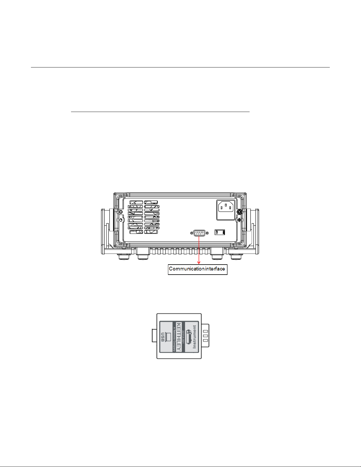
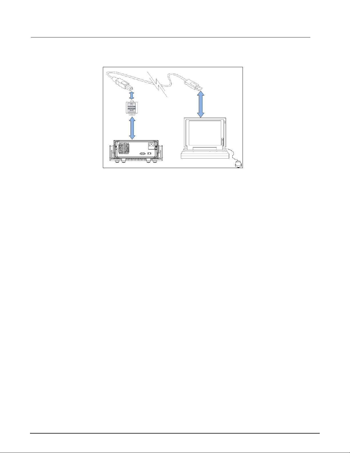
Communication interface
The DB9 interface connector on the rear panel of Mode 2231A-30-3 power supply is TTL level, and
you need to use a Model 2231A-001 USB adapter to connect DB9 interface with a PC.
Section 4
Remote communi cat ion
Figure 12: Communication interface
Model 2231A-001 USB Adapter
Figure 13: Model 2231A-001 USB Adapter
You can use 2231A-001 communication module and a standard USB straight-through cable (one end
is B connector, and the other end is A connector) to connect the DB9 interface connector of the power
supply to a USB interface.
Power
supply
Page 37
Section 4: Remote communication Model 2231A Triple-channel DC Power Supply Reference Manual
Figure 13: Communication connection
4-2 077100401/September 2014
Page 38

Section 5
SCPI command reference
In this section:
Common commands ................................................................. 5-2
APPly subsystem ...................................................................... 5-6
Calibration subsystem ............................................................... 5-7
DISPlay subsystem ................................................................... 5-9
INSTrument subsystem .......................................................... 5-10
MEASure subsystem .............................................................. 5-12
OUTPut subsystem ................................................................. 5-14
SYSTem subsystem ............................................................... 5-17
STATus subsystem ................................................................. 5-19
SOURce subsystem ................................................................ 5-24
Status model ........................................................................... 5-29
Error message ........................................................................ 5-31
5-1
Page 39

Section 5: SCPI command reference Model 2231A Triple-channel DC Power Supply Reference Manual
After connecting the 2231A-001 communication connector with PC, you need to send the following
command to switch the instrument in remote mode: SYSTem:REMote.
Common commands
This section describes the general remote interface commands and common commands. The general
remote interface commands are commands that have the same general meaning, regardless of the
instrument you use.
The common commands perform operations such as reset, wait-to-continue, and status .
Common commands always begin with an asterisk (*) and may include one or more parameters. The
command keyword is separated from the first parameter by a blank space.
You can group command messages when you send them to the instrument. Use a semicolon to
separate multiple commands, as shown below:
*RST; *CLS; *ESE 32; *OPC?
Although the commands in this section are shown in uppercase, common commands are not case
sensitive (you can either use uppercase or lowercase)
*CLS
This command clears the event registers and error queues.
Item Description
Group System
Syntax *CLS
Related Commands *ESE?, *STB?
*ESE
This command sets or queries the bits in the Event Status Enable Register(ESER). The ESER is an eight-bit
register that determines which bits in the Standard Event Status Register (SESR) will set the ESB bit in the Status
Byte Register (SBR).
Item Description
Group System
Syntax *ESE <N>
*ESE?
Related Commands *CLS, *SER?
Bit definitions of the standard event register
5-2 077100401/September 2014
Page 40
Model 2231A Triple-channel DC Power Supply Reference Manual Section 5: SCPI command reference
Bit Position 7 6 5 4 3 2 1 0
Bit Name PON Not used CME EXE DDE QYE Not used OPC
Bit Weight
128 32 16 8 4 1
PON Power-on
CME Command error
EXE Execution error
DDE Device-dependent error
QYE Query error
OPC Operation complete
*ESR?
This command reads the value of standard event status register. Once this command executed, the standard
event status register is reset. The bit definition for the standard event status register is as the same as the
standard event status enable register.
Item Description
Group Status
Syntax *ESR?
Related Commands *CLS, *OPC
*IDN?
This command reads information about the power supply. It returns a parameter that contains four segments
divided by a comma. Example: Keithley instruments, 2231A-30-3, 0123456789ABCDEFGH, 1.01-1.04.
Item Description
Group System
Syntax *IDN?
Related Commands *CLS, *SER?
*OPC
This command sets the OPC bit in the standard event register to 1 when all o ther co mm and s are compl ete.
Item Description
Group System
Syntax *OPC <N>
*OPC?
Related Commands None
*RST
077100401/September 2014 5-3
Page 41

Section 5: SCPI command reference Model 2231A Triple-channel DC Power Supply Reference Manual
This command is to reset the power supply to default settings.
Item Description
Group Status
Syntax *RST
Related Commands None
*SRE
This command is to set or query the status byte enable register. Setting this parameter can determine which byte
value of the status byte register is 1, and the byte will set the RQS bit of the status byte register to 1. The bit
definition of the status byte enable register is as the same as the status byte.
Item Description
Group System
Syntax *SRE <n>
*SRE?
Related Commands *STB?
*STB?
This command is to read the data from status byte register.
Item Description
Group Status
Syntax *STB?
Related Commands *SER?
Bit definitions for the status byte register:
Bit Position 7 6 5 4 3 2 1 0
Bit Name OPER RQS ESB MAV QUES EAV no use no use
Bit Weight 128 64 32 16 8 4
*TRG
This command initiates a trigger signal when the power supply trigger source is a command from the bus. Its function is the
same as the TRIGger command.
Item Description
Group Trigger
Syntax *TRG
Related Commands *trigger
5-4 077100401/September 2014
Page 42

Model 2231A Triple-channel DC Power Supply Reference Manual Section 5: SCPI command reference
*SAV
This command is to save the current setups of the power supply into specified memory. These setups contain current, voltage,
and the max voltage.
Item Description
Group System
Syntax *sav <NR1>
Arguments 0 to 30
Related Commands *RCL
*RCL
This command is to recall the setups you saved in the specified memory location.
Item Description
Group System
Syntax *RCL <NR1>
Arguments 0 to 30
Related Commands *SAV
*TST?
This command is to initialize a self-test and reports any errors.
Item Description
Group System
Syntax *TST
Returns A return value of 0 means the self-test passes; if there is an error, the
error code refers to Table 7
*WAI
This command is to prevent the instrument from executing further commands or queries until all pending
commands are complete.
Item Description
Group System
Syntax *WAI
Related Commands *TRG
077100401/September 2014 5-5
Page 43

Section 5: SCPI command reference Model 2231A Triple-channel DC Power Supply Reference Manual
*PSC
This command is to set and query the power on status flag that controls the automatic power on status of SRER
and ESER.
Item Description
Group SOURCE
Syntax *PSC
*PSC?
Related Commands
APPly subsystem
The commands in this subsystem set voltage and current levels.
[SOURce:]APPLy
This command is to select channels and set voltage and current levels with a single command.
Item Description
Group Apply
Syntax [SOURce:]APPLy {CH1|CH2|CH3},{voltage|Max|Min|Def|Up|Down},
{current|Max|Min|Def|Up|Down}
[SOURce:]APPLy?
Arguments Arg1: CH1|CH2|CH3
Optional Arg2: voltage|Max|Min|Def|Up|Down
Optional Arg3: current|Max|Min|Def|Up|Down
Returns Arg1,Arg2,Arg3
Examples Appl ch1,max,min
[SOURce:]APPly:VOLTage[:LEVel][:IMMediate][:AMPLitude]
This command is to set voltage to all channels at the same time.
Item Description
Group Source
Syntax [SOURce:]APPly:VOLTage[:LEVel][:IMMediate][:AMPLitude]
[SOURce:]APPly:VOLTage[:LEVel][:IMMediate][:AMPLitude]?
Arguments Arg1: voltage setting for CH1
Optional Arg2: voltage setting for CH2
Optional Arg3: voltage setting for CH3
5-6 077100401/September 2014
Page 44

Model 2231A Triple-channel DC Power Supply Reference Manual Section 5: SCPI command reference
Unit V
Returns None
Examples APP:VOLT 3,3,1
[SOURce:]APPly:CURRent[:LEVel][:IMMediate][:AMPLitude]
This command is to set current to all channels at the same time.
Item Description
Group Source
Syntax [SOURce:]APPly:CURRent[:LEVel][:IMMediate][:AMPLitude]
[SOURce:]APPly:CURRent[:LEVel][:IMMediate][:AMPLitude]?
Arguments Arg1: current setting for CH1
Optional Arg2: current setting for CH2
Optional Arg3: current setting for CH3
Unit A
Returns None
Examples AP P :CURR 1,1,0.6
CALibration subsystem
The commands in this subsystem configure and control the calibration operations.
CALibration:SECure:[STATe]
This command clears all the specified strings and returns the display back to voltage and current readingS.
Item Description
Group Calibration
Syntax CALibration:SECure:[STATe] {<ON|OFF>,[<password>]}
CALibration:SECure:STATe?
Arguments 0|1|ON|OFF, ‘2231’
Returns 0|1
Examples CAL:SEC 0, ‘2231’; CAL:SEC OFF
CALibrate:VOLTage:LEVel
077100401/September 2014 5-7
Page 45

Section 5: SCPI command reference Model 2231A Triple-channel DC Power Supply Reference Manual
This command is to set the voltage calibration points. P1, P2, P3 and P4 must be calibrated in numeric order.
Item Description
Group Calibration
Syntax CALibrate:VOLTage:LEVel <level>
Argument P1|P2|P3|P4
Returns None
Examples Cal:volt:lev P1
CALibrate:VOLTage[:DATA] <numeric value>}
This command is to return the actual output voltage value of the calibrat ion point.
Item Description
Group Calibration
Syntax CALibrate:VOLTage[:DATA] <NRf>
Argument Voltage level
Returns <NRf>
Examples CAL:VOLT 30.0002V
CALibrate:CURRent:LEVel
This command is to set the current calibration points. P1, P2 must be calibrated in numeric order.
Item Description
Group Calibration
Syntax CALibrate:CURRent:LEVel <level>
Arguments P1|P2
Returns <NRf>
Examples Cal:curr P1
CALibrate:CURRent[:DATA] {<numeric value>}
This command is to return the actual output current value of the calibration point.
Item Description
Group Calibration
Syntax CALibration:CURRent [:DATA] <NRf>
Arguments Current level
Item Description
Returns None
Examples CAL:CURR 3.0002A
5-8 077100401/September 2014
Page 46

Model 2231A Triple-channel DC Power Supply Reference Manual Section 5: SCPI command reference
CALibration:SAVe
This command is to save calibration coefficient into nonvolatile memory.
Item Description
Group Calibration
Syntax CALibration:SAVe
Arguments None
Returns None
Examples Cal:sav
CALibration:INITital
This command is to set the current calibration coefficient as the default value.
Item Description
Group Calibration
Syntax CALibration:INITital
Arguments None
Returns None
Examples Cal:init
CALibrate:STRing
This command is to write or query the calibration information of the instrument.
Item Description
Group Calibration
Syntax CALibration:STRing <string>
CALibrate:STRing?
Arguments char (22 character maximum)
Returns String
Examples Cal:str “march 2014”
DISPlay subsystem
This subsystem contains commands that control the front-panel display.
DISPlay[:WINDow][:STATe]
077100401/September 2014 5-9
Page 47

Section 5: SCPI command reference Model 2231A Triple-channel DC Power Supply Reference Manual
This command is to set or query the state of the instrument display. A value of 0 indicates no display.
Item Description
Group Display
Syntax DISPlay[:WINDow][:STATe] <Arguments>
DISPlay[:WINDow][:STATe]?
Arguments 0|1 |ON|OFF
Returns 0|1
Examples DISP 0
DISPlay[:WINDow]:TEXT[:DATA]
This command shows a specified string on the screen or queries the screen display.
Item Description
Group Display
Syntax DISPlay[:WINDow]:TEXT[:DATA] <String>
DISPlay[:WINDow]:TEXT[:DATA]?
Arguments String with “ “
Returns None
Examples Disp:text “hello keit hley ”
DISPlay[:WINDow]:TEXT:CLEar
This command is to clear all the specified display strings and return the display to voltage and current readings.
Item Description
Group Display
Syntax DISPlay[:WINDow]:TEXT:CLEar
Arguments None
Returns None
Examples Disp:text:cle
INSTrument subsystem
The commands in this subsystem configure and control the channel selection operations.
INSTrument[:SELect]
This command is to select the channel.
Item Description
5-10 077100401/September 2014
Page 48

Model 2231A Triple-channel DC Power Supply Reference Manual Section 5: SCPI command reference
Group Channel
Syntax INSTrument[:SELect] {CH1|CH2|CH3}
INSTrument[:SELect]?
Arguments CH1|CH2|CH3
Returns CH1/CH2/CH3
Examples Inst CH2
INSTrument:NSELect
This command is to select the channel.
Item Description
Group Channel
Syntax INSTrument:NSELect <NR1>
INSTrument:NSELect?
Arguments Arg 1, Arg 2, Arg 3
Returns channel 1, channel 2, and channel 3
Examples INST:NSEL 3
INSTrument:COMbine:SERies
This command is to combine the voltage reading of CH1 and CH2 when they are connected in a series.
Item Description
Group Channel
Syntax INSTrument:COMbine:SERies
Arguments None
Returns None
Examples Inst:com:ser
INSTrument:COMbine:PARAllel
This command is to combine the current reading of CH1 and CH2 when they are connected in parallel.
Item Description
Group Channel
Syntax INSTrument:COMbine:PARAllel
Arguments None
Returns None
Item Description
Examples Inst:com:ser
077100401/September 2014 5-11
Page 49
Section 5: SCPI command reference Model 2231A Triple-channel DC Power Supply Reference Manual
INSTrument:COMbine:TRACk
This command is to set CH1and CH2 in track mode.
Item Description
Group Channel
Syntax INSTrument:COMbine:TRACk
Arguments None
Returns None
Examples Inst:com:trac
INSTrument:COMbine:OFF
This command is to turn off series/parallel/tracking modes.
Item Description
Group Channel
Syntax INSTrument:COMbine:OFF
INSTrument:COMbine:OFF
Arguments None
Returns NONE/SERIES/PARALLEL/TRACK
Examples Inst:com:off
INSTrument:COUPle[:TRIGger]
This command is to determine which channels will respond to the trigger command.
Item Description
Group Channel
Syntax INSTrument:COUPle[:TRIGger] <Arguments>
INSTrument:COUPle[:TRIGger]? <Arguments>
Arguments CH1|CH2|CH3
Returns None
Examples Inst:coup ch1.ch2
MEASure subsystem
These commands make measurements.
5-12 077100401/September 2014
Page 50

Model 2231A Triple-channel DC Power Supply Reference Manual Section 5: SCPI command reference
MEASure[:SCALar]:VOLTage[:DC]?
FETCh[:VOLTage][:DC]?
The first command is to initiate and execute a new measurement of the voltage.
The second command is to query the current voltage.
Item Description
Group Measure
Syntax MEASure[:SCALar]:VOLTage[:DC]?
Arguments None
Returns <NR2> is the new measured voltage with the unit V
Examples MEAS:VOLT?
MEASure[:SCALar]:CURRent[:DC]?
FETCh:CURRent[:DC]?
This first command is to initiate and execute a new current measurement.
The second command is to query the current reading.
Item Description
Group Measure
Syntax MEASure[:SCALar]:CURRent[:DC]?
FETCh:CURRent[:DC]?
Arguments None
Returns <NR2> is the current value in unit A
Examples MEAS:CURR?
MEASure[:SCALar]:POWer[:DC]?
FETCh:POWer[:DC]?
This first command is to initiate and execute a new power measurement.
The second command is to query the current power.
Item Description
Group Measure
Syntax MEASure[:SCALar]:POWer?
FETCh:POWer[:DC]?
Item Description
077100401/September 2014 5-13
Page 51

Section 5: SCPI command reference Model 2231A Triple-channel DC Power Supply Reference Manual
Arguments None
Returns <NR2>is the power value in unit W
Examples MEAS:POW?
OUTPut subsystem
The output subsystem provides information and settings that control the source output.
OUTPut[:STATe][:ALL]
This command is to set the output state of all three channels.
Item Description
Group Output
Syntax OUTPut [:STATe] <bool>
OUTPut:STATe[:ALL]?
Arguments 0|1|ON|OFF
Returns 0|1
Examples Outp 1
CHANnel:OUTPut[:STATe]
This command is to control the output status of the current channel.
Item Description
Group Output
Syntax CHANnel:OUTPut[:STATe] <bool>
[SOURce:]CHANnel:OUTPut[:STATe]?
Arguments 0|1|ON|OFF
Returns 0|1
Examples Chan:outp 1
OUTPut:ENABle
This command enables or disables the current output function that was selected in the Enable Channels menu.
Item Description
Group Output
Syntax OUTPut:ENABle
Item Description
5-14 077100401/September 2014
Page 52

Model 2231A Triple-channel DC Power Supply Reference Manual Section 5: SCPI command reference
Arguments 0|1
Returns 0|1
Examples Outp:enab 1
OUTPut:TIMer[:STATe]
This command is to set the output timer state for the presently selected channel.
Item Description
Group Output
Syntax OUTPut:TIMer[:STATe] <bool> <Arguments>
OUTPut:TIMer:STATe?
Arguments 0|1|ON|OFF
Returns 0|1
Examples Outp:tim 1
OUTPut:TIMer:DELay
This command is to set the delay time for the output timer function.
Item Description
Group Output
Syntax OUTPut:TIMer:DELay <Arguments>
OUTPut:TIMer:DELay?
Arguments 0.1-99999.9
Unit s (seconds)
Returns The timer delay
Examples Outp:tim:del 5
Outp:tim:del?
OUTPut:TRACk[:STATe]
This command is to set the tracking status of CH1 and CH2.
Item Description
Group Output
Syntax OUTPut:TRACk[:STATe] <bool>
[SOURce:]OUTPut:TRACk[:STATe]?
Arguments 0|1|ON|OFF
Returns 0|1
Item Description
077100401/September 2014 5-15
Page 53

Section 5: SCPI command reference Model 2231A Triple-channel DC Power Supply Reference Manual
Examples Outp:trac 1
OUTPut:SERies[:STATe]
This command is to combine the CH1 and CH2 voltage readings when CH1 and CH2 c onn ec ted in para lle l.
Item Description
Group Output
Syntax OUTPut:SERies[:STATe] <Arguments>
OUTPut:SERies[:STATe]?
Arguments 0|1|ON|OFF
Returns 0|1
Examples Outp:ser 0
Outp:ser?
OUTPut: PARallel [:STATe]
This command is to combine the CH1 and CH2 current readings when CH1 and CH2 are wired in parallel
connection.
Item Description
Group Output
Syntax OUTPut: PARallel [:STATe] <Arguments>
OUTPut: PARallel [:STATe]?
Arguments 0|1|ON|OFF
Returns 0|1
Examples Outp:para 1
5-16 077100401/September 2014
Page 54

Model 2231A Triple-channel DC Power Supply Reference Manual Section 5: SCPI command reference
SYSTem subsystem
This subsystem contains commands that affect the overall operation of the instrument, such as
autozero, beeper, communications, event logs, and time.
SYSTem:ERRor?
This command is to query the error code and error information occurring in the power supply.
Item Description
Group System
Syntax SYSTem:ERRor?
Arguments None
Returns Both the error code and the error information
Examples Syst:err?
SYSTem:VERSion?
This command is to query the SCPI version of the instrument.
Item Description
Group System
Syntax SYSTem:VERSion?
Arguments None
Returns <NR2> is the SCPI version of the power supply
Examples Syst:vers?
SYSTem:REMote
This command is to switch the power supply into remote control mode.
Item Description
Group System
Syntax SYSTem:REMote
Arguments None
Returns None
Examples syst:rem
SYSTem:LOCal
This command is to switch the power supply into control from the front panel.
077100401/September 2014 5-17
Page 55

Section 5: SCPI command reference Model 2231A Triple-channel DC Power Supply Reference Manual
Item Description
Group System
Syntax SYSTem:LOCal
Arguments None
Returns None
Examples Syst:loc
SYSTem:RWLock
This command is to switch the power supply into remote control mode and locks all of the buttons on the front
panel.
Item Description
Group System
Syntax SYSTem:RWLock
Arguments None
Returns None
Examples SYST:RWL
SYSTem:MODUle?
This command is to query the module of the power supply.
Item Description
Group System
Syntax SYSTem:MODUle?
Arguments None
Returns The module of the power supply, for example 2231,1.04
Examples Syst:modu?
SYSTem:BEEPer
This command is to test the beeper function of the power supply. If it passes, a beep is issued.
Item Description
Group System
Syntax SYSTem:BEEPer
Arguments None
Returns None
Examples Syst:beep
5-18 077100401/September 2014
Page 56

Model 2231A Triple-channel DC Power Supply Reference Manual Section 5: SCPI command reference
STATus subsystem
The STATus subsystem controls the status registers of the Model 2231A-30-3.
STATus:QUEStionable[:EVENt]?
This command is to return to the contents of the questionable event register. After this command executed, the
questionable event register is reset.
Item Description
Group Status
Syntax STATus:QUEStionable[:EVENt]?
Arguments None
Returns <NR1> is a decimal integer representation of the contents of the
questionable event register. Range: 0 to 255
Examples Stat:ques?
STATus:QUEStionable:ENABle
This command is to set and query the contents of the questionable event enable register, The QENR is an
eight-bit mask register that determines which bits in the questionable event register should affect the state of
QUES bit in the status byte register.
Item Description
Group Status
Syntax STATus:QUEStionable:ENABle <NR1>
STATus:QUEStionable:ENABle?
Arguments <NR1> is a decimal integer ranging from 0 to 255, according to
which bits of the mask register of the QENR are set.
Returns <mask>
Examples Stat:ques:enab?
STATus:QUEStionable:CONDition?
This command is to query the questionable condition register.
Item Description
Group Status
Syntax STATus:QUEStionable: CONDition?
Arguments None
077100401/September 2014 5-19
Page 57

Section 5: SCPI command reference Model 2231A Triple-channel DC Power Supply Reference Manual
Returns <NR1>
Examples Stat:ques:cond?
STATus:PRESet
This command is to reset the status register.
Item Description
Group Status
Syntax STATus:PRESet
Arguments None
Returns None
Examples Stat:pres
STATus:QUEStionable:INSTrument[:EVENt]?
This command is to query the questionable instrument status event register of the instrument.
Item Description
Group Status
Syntax STATus:QUEStionable:INSTrument[:EVENt]?
Arguments None
Returns <NR1>is a decimal integer representation of the contents of the
questionable event register. Range: 0~255
Examples Stat:ques:inst?
STATus:QUEStionable:INSTrument:ENABle
This command is to query the questionable instrument status event register of the power supply.
Item Description
Group Status
Syntax STATus:QUEStionable:INSTrument:ENABle
STATus:QUEStionable:INSTrument:ENABle?
Arguments 0~255
Returns <NR1> is a decimal integer ranging from 0 to 255, according to which the bits of
the mask register of the questionable register for the specified channel are set.
Examples Stat:ques:inst:enab?
STATus:QUEStionable:INSTrument:ISUMmary<x>[:EVENt]?
5-20 077100401/September 2014
Page 58

Model 2231A Triple-channel DC Power Supply Reference Manual Section 5: SCPI command reference
This queries the operation event register of channel 1, channel 2, channel 3, where <x> is 1, 2 or 3.
Item Description
Group Status
Syntax STATus:QUEStionable:INSTrument:ISUMmary<x>[:EVENt]?
Arguments None
Returns <NR1> is a decimal integer representation of the contents of the
questionable event register for channel 1, channel 2, channel 3,
range: 0 to 255
Examples Stat:ques:inst:isum1?
STATus:QUEStionable:INSTrument:ISUMmary<X>:ENABle
This command is to modify or query the operation enable register summary of channel 1, channel 2, channel 3,
where <x> indicates 1, 2 or 3.
Item Description
Group Status
Syntax STATus:QUEStionable:INSTrument:ISUMmary<X>:ENABle
STATus:QUEStionable:INSTrument:ISUMmary<X>:ENABle?
Arguments <NR1> is a decimal integer representation of the bits of the mask register of
the questionable enable register of channel 1, channel 2, and channel 3
(ranging from 0 to 255).
Returns Same as arguments, 0 to 255
Examples Stat:ques:inst:isum2:enab 12
Stat:ques:inst:isum2:enab?
STATus:QUEStionable:INSTrument:ISUMmary<x>:CONDition?
This command queries the questionable condition register summary of a channel (1, 2, or 3), where <x> is 1, 2 or
3.
Item Description
Group Status
Syntax STATus:QUEStionable:INSTrument:ISUMmary<x>:CONDition?
Arguments None
Returns <NR1> is a decimal integer representation of the contents of the questionable
condition register. Range: 0 to 255.
Examples Stat:ques:inst:isum2:cond?
STATus:OPERation[:EVENt]?
This command is to query the content of the operation event register.
077100401/September 2014 5-21
Page 59

Section 5: SCPI command reference Model 2231A Triple-channel DC Power Supply Reference Manual
Item Description
Group STATus
Syntax STATus:OPERation [:EVENt]?
Arguments None
Returns 0~255
Examples Stat:oper?
STATus:OPERation:CONDition?
This command is to query the contents of the operation condition register.
Item Description
Group Status
Syntax STATus:OPERation:CONDition?
Arguments None
Returns 0~255
Examples Stat:oper:cond?
STATus:OPERation:ENABle
This command is to set or query the contents of the operation enable register.
Item Description
Group Status
Syntax STATus:OPERation:ENABle <NRf>
STATus:OPERation:ENABle?
Arguments 0~255
Returns 0~255
Examples Stat:oper:enab?
STATus:OPERation:INSTrument[:EVENt]?
This command is to return to the contents of the operation event register. After this command is sent, the
operation event register is reset.
Item Description
Group Status
Syntax STATus:OPERation:INSTrument[:EVENt]?
Arguments None
Returns 0 to 255
Examples Stat:oper:inst?
5-22 077100401/September 2014
Page 60

Model 2231A Triple-channel DC Power Supply Reference Manual Section 5: SCPI command reference
STATus:OPERation:INSTrument:ENABle
This command is to set or query the contents of the operation instrument enable register.
Item Description
Group Status
Syntax STATus:OPERation:INSTrument:ENABle
STATus:OPERation:INSTrument:ENABle?
Arguments 0~255
Returns 0~255
Examples Stat:oper:inst:enab?
STATus:OPERation:INSTrument:ISUMmary<x>[:EVENt]?
This command is to query the operation event register summary of a channel.
Item Description
Group Status
Syntax STATus:OPERation:INSTrument:ISUMmary<x>[:EVENt]?
Arguments None
Returns 0~255
Examples Stat:oper:inst:isum2?
STATus:OPERation:INSTrument:ISUMmary<x>:ENABle
This command is to modify or query the operation enable register of channel 1, 2 or 3, where <x> is 1, 2 or 3.
Item Description
Group Status
Syntax STATus:OPERation:INSTrument:ISUMmary<x>:ENABle
STATus:OPERation:INSTrument:ISUMmary<x>:ENABle?
Arguments 0~255
Returns 0~255
Examples Stat:oper:inst:isum3:enab?
STATus:OPERation:INSTrument:ISUMmary<x>:CONDition?
This command is to query the operation condition register of channel 1/2/3.
Item Description
Group Status
077100401/September 2014 5-23
Page 61

Section 5: SCPI command reference Model 2231A Triple-channel DC Power Supply Reference Manual
Syntax STATus:OPERation:INSTrument:ISUMmary<x>:CONDition?
Arguments None
Returns 0~255
Examples Stat:oper:inst:isum1:cond?
SOURce subsystem
The commands in the SOURce subsystem configure and control the current source and voltage
source.
[SOURce:]CHANnel:OUTPut[:STATe]
This command is to set the output state of the currently selected channel.
Item Description
Group Source
Syntax [SOURce:]CHANnel:OUTPut[:STATe]
[SOURce:]CHANnel:OUTPut[:STATe]?
Arguments 0|1|ON|OFF
Returns 0|1
Examples Chan:outp 1
Chan:outp?
[SOURce:]CURRent[:LEVel][:IMMediate][:AMPLitude]
This command is to set or query the current value for the present channel.
Item Description
Group Source
Syntax [SOURce:]CURRent [:LEVel] <NRf>
[SOURce:]CURRent[:LEVel][:IMMediate][:AMPLitude]?
Arguments MIN TO MAX|MIN|MAX|UP|DOWN|DEF
Unit A| mA
Returns <NR2> is the current setting
Examples Curr 2
Curr?
[SOURce:]CURRent[:LEVel]:UP[:IMMediate][:AMPLitude]
This command is to increase the current value by one step. Set the current step using the command:
[SOURce:]CURRent[:LEVel][:IMMediate]:STEP[:INCRement]
5-24 077100401/September 2014
Page 62

Model 2231A Triple-channel DC Power Supply Reference Manual Section 5: SCPI command reference
Item Description
Group Source
Syntax [SOURce:]CURRent[:LEVel]:UP[:IMMediate][:AMPLitude]
Arguments None
Returns None
Examples Curr:up
[SOURce:]CURRent[:LEVel]:DOWN[:IMMediate][:AMPLitude]
This command is to decrease the current value by one step.
Item Description
Group Source
Syntax [SOURce:]CURRent[:LEVel]:DOWN[:IMMediate][:AMPLitude]
Arguments None
Returns None
Examples Curr:down
[SOURce:]CURRent[:LEVel][:IMMediate]:STEP[:INCRement]
This command is to set the current stepping.
Item Description
Group Source
Syntax [SOURce:]CURRent[:LEVel][:IMMediate]:STEP[:INCRement]
[SOURce:]CURRent[:LEVel][:IMMediate]:STEP[:INCRement]?
Arguments Current value
Unit A|mA|Ua
Returns Current value
Examples Curr:step 0.1
Curr:step?
[SOURce:]CURRent[:LEVel]:TRIGgered[:IMMediate][:INCRement]
This command is to set or query the current level for the trigger function. When you set the trigger voltage and
current and send the trigger command to the instrument, the voltage and current will change to the trigger voltag e
and current that you set.
Item Description
Group Source
Syntax [SOURce:]CURRent[:LEVel]:TRIGgered[:IMMediate][:INCRement]
077100401/September 2014 5-25
Page 63

Section 5: SCPI command reference Model 2231A Triple-channel DC Power Supply Reference Manual
[SOURce:]CURRent[:LEVel]:TRIGgered[:IMMediate][:INCRement]?
Arguments Current value |Min|Max|Def|Up|Down
Returns Currnet value
Examples Curr:trig 1
[SOURce:]VOLTage[:LEVel][:IMMediate][:AMPLitude]
This command is to set the voltage value for the current output.
Item Description
Group Source
Syntax [SOURce:]VOLTage[:LEVel] <NRf>
[SOURce:]VOLTage[:LEVel]?
Arguments MIN TO MAX|MIN|MAX|UP|DOWN|DEF
Unit V | mV | KV
Returns <voltage>
Examples Volt 19
[SOURce:]VOLTage[:LEVel]:UP[:IMMediate][:AMPLitude]
This command is to increase the voltage level by one step; the value of the step value also can be set by this
command.
Item Description
Group Source
Syntax [SOURce:]VOLTage[:LEVel]:UP[:IMMediate][:AMPLitude]
Arguments None
Returns None
Examples Volt:up
[SOURce:]VOLTage[:LEVel]:DOWN[:IMMediate][:AMPLitude]
This command is to decrease the voltage level by one step.
Item Description
Group Source
Syntax [SOURce:]VOLTage[:LEVel]:DOWN[:IMMediate][:AMPLitude]
Arguments None
Returns None
Examples Volt:down
5-26 077100401/September 2014
Page 64

Model 2231A Triple-channel DC Power Supply Reference Manual Section 5: SCPI command reference
[SOURce:]VOLTage[:LEVel][:IMMediate]:STEP[:INCRement]
This command configures voltage stepping.
Item Description
Group Source
Syntax [SOURce:]VOLTage[:LEVel][:IMMediate]:STEP[:INCRement] <voltage>
[SOURce:]VOLTage[:LEVel][:IMMediate]:STEP[:INCRement]?
Arguments The voltage step for UP/DOWN adjustment
Unit kV|V|mV|uV
Returns None
Examples Volt:step 0.01
Volt:step?
[SOURce:]VOLTage[:LEVel]:TRIGgered[:IMMediate][:INCRement]
This command is to set the level for the trigger function. When you set the trigger voltage and current and send
the trigger command to the instrument, the voltage and current can switch to the trigger voltage and current that
you set before.
Item Description
Group Source
Syntax [SOURce:]VOLTage[:LEVel]:TRIGgered[:IMMediate][:INCRement]
[SOURce:]VOLTage[:LEVel]:TRIGgered[:IMMediate][:INCRement]?
Arguments 0 to max rated voltage
Unit kV|V|mV|uV
Returns Trigger voltage
Examples Volt:trig 12
[SOURce:]VOLTage:LIMIT[:LEVel]
This command is to set the voltage limit for the present channel.
Item Description
Group Source
Syntax [SOURce:]VOLTage:LIMIT[:LEVel]
[SOURce:]VOLTage:LIMIT[:LEVel]?
Arguments 0 to max rated voltage||Min|Max|def
Returns The voltage limit
077100401/September 2014 5-27
Page 65

Section 5: SCPI command reference Model 2231A Triple-channel DC Power Supply Reference Manual
Examples Volt:limit 25
[SOURce:]VOLTage:LIMit:STATe
This command is to enable or disable the voltage limit function.
Item Description
Group Source
Syntax [SOURce:]VOLTage:LIMit:STATe <bool>
[SOURce:]VOLTage:LIMit:STATe?
Arguments 1|0(1:enable)
Returns The voltage limit
Examples Volt:limit 25
5-28 077100401/September 2014
Page 66

Model 2231A Triple-channel DC Power Supply Reference Manual Section 5: SCPI command reference
Status model
077100401/September 2014 5-29
Page 67

Section 5: SCPI command reference Model 2231A Triple-channel DC Power Supply Reference Manual
BIT Signal Meaning
0
CV
1
CC
2
CAL
3
ON
1
INST1
2
INST2
3
INST3
1 ISUM
0
CV
1
CC
1
INST1
2
INST2
3
INST3
4
OTP
13
ISUM
0
OPC
2
QYE
3
DDE
4
EXE
5
CME
7
PON
2
EAV
3
QUES
4
MAV
5
ESB
6
RQS
7
OPER
Operation Instrument Summary Register
Constant voltage
Constant current
The power supply is calculating the new calibration parameter.
The output of the power supply is ON or OFF.
Operation Instrument Status Register
STATus:OPERation:INSTrument:ISUMmary1 is reported to INST1
STATus:OPERation:INSTrument:ISUMmary2 is reported to INST2
STATus:OPERation:INSTrument:ISUMmary3 is reported to INST3
Operation status register
Summary of STAT:OPER:INST
Questionable Instrument Summary Register
Constant voltage
Constant current
Questionable Instrument status Register
STATus:QUEStionable:INSTrument:ISUMmary1 is reported to INST1
STATus:QUEStionable:INSTrument:ISUMmary2 is reported to INST2
STATus:QUEStionable:INSTrument:ISUMmary3 is reported to INST3
Questionable Status Register
Over temperature protection
Summary of STAT:QUES:INST
Standard Event Register
Operation complete.
Query error. Data for output array is missing.
Device-dependent error. Data stored in the regi ster is miss in g or the error occurs in
preliminary checkout.
Execution error. The command parameter overflows or the condition is not right.
Command error. Syntax or semantic error occurs when receiving information.
Power on. The value is 1 when the power supply is reset.
Status Byte Register
Error buffer is available
If the questionable status regi s ter changes, QUES is 1.
Output buffer is available
If the standard event enable register changes, ESB is 1.
If the operation status register changes, OPER is 1.
5-30 077100401/September 2014
Page 68

Model 2231A Triple-channel DC Power Supply Reference Manual Section 5: SCPI command reference
Error messages
Code Description
0 'No Error'
1 'Module Initialization Lost'
2 'Initialization Lost'
3 'Module Calibration Lost'
4 'Eeprom failure'
101 'Too many numeric suffices'
110 'No input command'
114 'Error Para Units'
116 'Error Para Type'
117 'Error Para Count'
120 'Unmatched Quote'
140 'Unmatched Bracket'
150 'Invalid Command'
160 'No Entry'
165 'Too Many Dims'
170 'Too Many Commands'
180 'Command Exec Err'
190 'Error Rxd Parity'
191 'Error EEPROM'
121 'Error Config Data'
122 'Error Cal. Data'
123 'Error Factory Data'
170 ‘Invalid command’
180 'No entry in list'
190 'Too many dimensions'
191 'Too many char'
-200 'Execution error'
-221 'Settings conflict'
-222 'Data out of range'
077100401/September 2014 5-31
Page 69

Section 5: SCPI command reference Model 2231A Triple-channel DC Power Supply Reference Manual
Code Description
-223 'Too much data'
-224 'Illegal parameter value'
-225 'Out of memory'
-230 'Data Corrupt or Stale'
-310 'System error'
-350 'Too many errors'
-400 'Query error'
-410 'Query INTERRUPTED'
-420 'Query UN TERMINATED'
-430 'Query DEADLOCKED'
223 'Front panel buffer overrun'
224 'Front panel timeout’
225 'Front Crc Check error’
401 'CAL switch prevents’
402 'CAL password is incorrect'
403 'CAL not enabled'
404 'readback cal are incorrect'
405 'programming cal are incorrect '
5-32 077100401/September 2014
Page 70

Section 6
Additional Information
In this section:
Additional Model 2231A-30-3 information ................................. 6-1
Additional Model 2231A-30-3 information
For more information about the Model 2231A-30-3, refer to:
• The Product Information CD-ROM (shipped with the product) contains the product
documentation.
• The Keithley Instruments website (http://www.keithley.com) contains the most up-to-date
information. From the website, you can access:
The Knowledge Center, which contains the following handbooks:
The Low Level Measurements Handbook: Precision DC Current, Voltage, and Resistance
Measurements
Switching Handbook: A Guide to Signal Switching in Automated Test Systems
Application note s
Updated drivers
Updated firmware
6-1
• Your local Field Applications Engineer, sales partner, or distributor. They can help you with
product selection, configuration, and usage. Check the website for contact information.
Page 71

Page 72

In this appendix:
Introduction
The information in this section describes routine maintenance of the instrument that can be performed
by the operator.
Appendix A
Maintenance
Introduction .............................................................................. A-1
Line fuse replacement ............................................................. A-1
Cleaning the front-panel display .............................................. A-2
Line fuse replacement
On the back panel, you will find a small plastic cover below the power supply.
Make sure that the replacement fuse meets the specifications of the power supply.
Model 110 V 220 V
2231A-30-3 6.30 A TH 250V 3.15 A TH 250V
To replace the line fuse replacement, follow these steps:
1. Open the cover with a screwdriver.
2. Remove the power cord.
3. Use a screwdriver to remove the fuse box.
Page 73
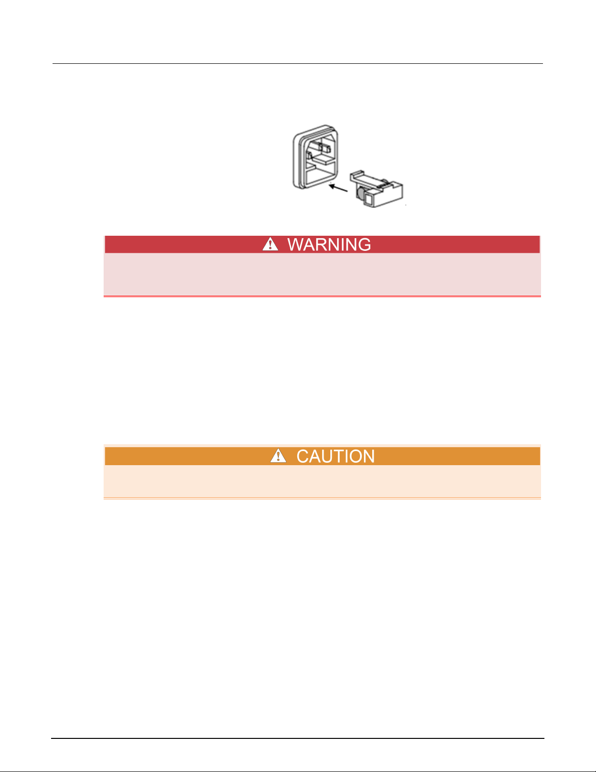
Appendix A: Maintenance Model 2231A-30-3 Triple-Channel DC Power Supply Reference Manual
4. Replace the fuse with a new fuse with the same ratings as the fuse you are removing; install it
into the fuse box and then insert the box cover.
Disconnect the line cord at the rear panel and remove all test leads connected to the
instrument before replacing the line fuse. Failure to do so could expose the operator to
hazardous voltages that could result in personal injury or death.
Cleaning the front-panel display
Inspect the power supply as often as operating conditions require.
To clean the exterior surface:
1. Remove loose dust on the outside of the power supply with a lint-free cloth. Be careful that you
do not scratch the display.
2. Use a soft cloth dampened with water to clean the power supply. Use an aqueous solution of 75
percent isopropyl alcohol for a more efficient cleaning.
To avoid damage to the surface of the power supply, you should not use any abrasive or chemical
cleaning agents.
A-2 077100401/September 2014
Page 74

Page 75

All Keithley trademarks and trade names are the property of Keithley Instruments.
All other trademarks and trade names are the property of their respective companies.
Specifications are subject to change without notice.
Corporate Headquarters • 28775 Aurora Road • Cleveland, Ohio 44139 • 440-248-0400 • Fax: 440-248-6168 • 1-888-KEITHLEY • www.keithley.com
Keithley Instruments
A Greater Measure of Confidence
7/14
 Loading...