

Page 1
INSTALLATION AND OPERATING INSTRUCTIONS
VARI-DRIVE
NEMA1 / IP20 SCR Variable Speed DC Motor Controls
Model KBWM-120 rated 1/100 - 1/3 HP (90 Volts DC) @ 115 Volts AC, 50/60 Hz
Model KBWM-240 rated 1/50 - 3/4 HP (180 Volts DC) @ 208/230 Volts AC, 50/60 Hz
A COMPLETE LINE OF MOTOR DRIVES
© 2001 KB Electronics, Inc.
The information contained in this manual is intended to be accurate. However, the manufacturer retains
the right to make changes in design which may not be included herein.
See Safety Warning on Page 1
See Page 2
TM
ARI- RIVE
VD
TM
DC MOTOR
SPEED CONTROL
50
40
30
20
10
0
(%) SPEED
!
60
70
80
90
100
ON
OFF
TM
TM
Page 2

TABLE OF CONTENTS
Section Page
i. Simplified Operating Instructions . . . . . . . . . . . . . . . . . . . . . . . . . . . . . . . . . . . . . . . . . . 1
ii. Safety Warning . . . . . . . . . . . . . . . . . . . . . . . . . . . . . . . . . . . . . . . . . . . . . . . . . . . . . . . 1
I. Introduction . . . . . . . . . . . . . . . . . . . . . . . . . . . . . . . . . . . . . . . . . . . . . . . . . . . . . . . . . . 2
II. Control Setup . . . . . . . . . . . . . . . . . . . . . . . . . . . . . . . . . . . . . . . . . . . . . . . . . . . . . . . . . 5
III. Mounting . . . . . . . . . . . . . . . . . . . . . . . . . . . . . . . . . . . . . . . . . . . . . . . . . . . . . . . . . . . . 6
IV. Wiring . . . . . . . . . . . . . . . . . . . . . . . . . . . . . . . . . . . . . . . . . . . . . . . . . . . . . . . . . . . . . . 6
V. Operation . . . . . . . . . . . . . . . . . . . . . . . . . . . . . . . . . . . . . . . . . . . . . . . . . . . . . . . . . . . . 8
VI. Trimpot Adjustments and Control Functions . . . . . . . . . . . . . . . . . . . . . . . . . . . . . . . . . . 8
VII. Limited Warranty . . . . . . . . . . . . . . . . . . . . . . . . . . . . . . . . . . . . . . . . . . . . . . . . . . . . . 14
Tables
1. General Performance Specifications . . . . . . . . . . . . . . . . . . . . . . . . . . . . . . . . . . . . . . . . 2
2. Electrical Ratings . . . . . . . . . . . . . . . . . . . . . . . . . . . . . . . . . . . . . . . . . . . . . . . . . . . . . .3
3. Plug-in Horsepower Resistor® Chart . . . . . . . . . . . . . . . . . . . . . . . . . . . . . . . . . . . . . . . . 5
4. Armature Fuse Selection Chart . . . . . . . . . . . . . . . . . . . . . . . . . . . . . . . . . . . . . . . . . . . 5
5. Terminal Block Wiring Information . . . . . . . . . . . . . . . . . . . . . . . . . . . . . . . . . . . . . . . . . 6
6. Field Connection (Shunt Wound Motors Only) . . . . . . . . . . . . . . . . . . . . . . . . . . . . . . . . 7
Figures
1. Control Layout . . . . . . . . . . . . . . . . . . . . . . . . . . . . . . . . . . . . . . . . . . . . . . . . . . . . . . . .3
2. Mechanical Specifications . . . . . . . . . . . . . . . . . . . . . . . . . . . . . . . . . . . . . . . . . . . . . . . 4
3. Motor Voltage Selection (J2) (Model KBWM-240 Only) . . . . . . . . . . . . . . . . . . . . . . . . . . 6
4. AC Line and Armature Connection . . . . . . . . . . . . . . . . . . . . . . . . . . . . . . . . . . . . . . . . . 6
5A. Full Voltage Field . . . . . . . . . . . . . . . . . . . . . . . . . . . . . . . . . . . . . . . . . . . . . . . . . . . . . . 7
5B. Half Voltage Field . . . . . . . . . . . . . . . . . . . . . . . . . . . . . . . . . . . . . . . . . . . . . . . . . . . . . . 7
6A. Accel Trimpot Adjustment . . . . . . . . . . . . . . . . . . . . . . . . . . . . . . . . . . . . . . . . . . . . . . . . 9
6B. Decel Trimpot Adjustment . . . . . . . . . . . . . . . . . . . . . . . . . . . . . . . . . . . . . . . . . . . . . . . . 9
7. Internal Connection Diagram . . . . . . . . . . . . . . . . . . . . . . . . . . . . . . . . . . . . . . . . . . . . 11
ii
Page 3

i. KBWM-120, 240 SIMPLIFIED OPERATING INSTRUCTIONS
A. Power Connection – Wire AC line to ter-
minals L1 and L2. Be sure the model number corresponds to the correct input voltage.
B. Permanent Magnet (PM) Motor
Connection (Two-Wire Type) – Wire
the motor armature leads to terminals
A(+) and A(-). Be sure the motor voltage corresponds to the control voltage rating and model number.
Note: Although control is specifically designed for PM motors it can also be used for
shunt wound motors. (See Section IV D, page. 7.)
C. Ground – Be sure to earth ground the control by attaching a ground wire to the green stud
located between the Bx knockouts.
D. Plug-in Horsepower Resistor®** – The correct Plug-in Horsepower Resistor® must be
installed for optimum performance. (See Section II A, p. 5.)
E. Armature Fuse** – The correct value armature fuse must be installed for maximum pro-
tection. (See Section II C, p. 5.)
F. Trimpot Settings – All trimpots have been set according to Figure 1, page 3 and Section VI, page 8.
G. Jumper J2 is provided on Model KBWM-240 only and is factory set to “180V” position.
For step-down operation (208/230 Volts AC line input and 0-90 Volts DC output), set J2 to
the “90V” position. See Figure 3, on page 6.
**
This control will not operate without installing the proper size Plug-in Horsepower Resistor® and armature fuse
– supplied separately.
Model Number
AC Line Voltage
VAC 50/60 Hz
Armature
Voltage (VDC)
KBWM-120
KBWM-240
115
208/230
0 – 90
0 – 90*, 180
1
IMPORTANT – You must read these simplified operating instructions before proceeding. These
instructions are to be used as a reference only and are not intended to replace the detailed
instructions provided herein. You must read the Safety Warning before proceeding.
MODEL NO. & VOLTAGE RATING
ii. SAFETY WARNING! Please read carefully
This product should be installed and serviced by a qualified technician, electrician, or electrical maintenance person familiar with its operation and the hazards involved. Proper installation, which includes wiring,
mounting in proper enclosure, fusing or other over current protection, and grounding can reduce the chance
of electrical shocks, fires, or explosion in this product or products used with this product, such as electric
motors, switches, coils, solenoids, and/or relays. Eye protection must be worn and insulated adjustment
tools must be used when working with control under power. This product is constructed of materials (plastics, metals, carbon, silicon, etc.) which may be a potential hazard. Proper shielding, grounding and filtering
of this product can reduce the emission of radio frequency interference (RFI) which may adversely affect
sensitive electronic equipment. If further information is required on this product, contact the Sales
Department. It is the responsibility of the equipment manufacturer and individual installer to supply this
Safety Warning to the ultimate end user of this product. (SW effective 9/2000).
This control contains electronic Start/Stop circuits that can be used to start and stop the control.
However these circuits are never to be used as safety disconnects since they are not fail-safe. Use only the
AC line for this purpose.
Be sure to follow all instructions carefully. Fire and/or electrocution can result due to improper use of
this product.
!
*See “G” below.
Page 4

I. INTRODUCTION
The KBWM™ Vari-Drive™ adjustable speed SCR control for DC motors offers proven reliability in a rugged all-metal NEMA-1/ IP20 enclosure. The Vari-Drives™ are equipped with the
ultimate KBMM™ speed control module. They are specifically designed for fractional horsepower permanent magnet (PM) DC motors. Two models are offered. The KBWM-120 is
designed for 115 VAC input and is rated 1/100-1/3 HP at 90 VDC. The KBWM-240 is
designed for 208/230 VAC input and is rated 1/50 – 3/4 HP @ 180 VDC.
Note: Model
KBWM-240 can also be used on 90 Volt DC motors. See Section IID, on page 6.
KB’s exclusive Plug-in Horsepower Resistor®* automatically presets the drive’s IR Comp. for
maximum performance and CL circuits for safe operation on various motors. Although factory calibrated, internal trimpots for MIN, MAX, IR, CL, ACCEL and DECEL can be used to
fine-tune the KBWM™ for specific applications. Connections to the control are via a barrier
terminal block. By changing the orientation of the front cover, the wiring can be brought in
either from the bottom or the top of the control.
Motor failure due to demagnetization is eliminated by the patented ultra-fast Direct-Fed™
current limit circuit. The controls contain AC line and armature* fusing, which provide protection against catastrophic failure. Auto-Inhibit®, a KB exclusive, allows the drive to be
turned on and off rapidly using the AC line without damage to the control and/or motor. The
internal CL LED is a diagnostic indicator that lights when the motor is overloaded.
A conveniently located front panel lighted rocker switch controls AC line input power to the drive.
*Plug-in Horsepower Resistor® and armature fuse supplied separately.
2
This product complies with all CE directives pertinent at the time of manufacture. Contact
factory for detailed installation and Declaration of Conformity. Installation of a CE approved
RFI filter (KBRF-200A [P/N 9945C] or equivalent) is required. Additional shielded motor cable and/or
AC line cables may be required along with a signal isolator (KBSI-240D [P/N 9431] or equivalent).
Parameter Specification
Speed Range Ratio 50:1
Armature Feedback Load Regulation (0 - Full Load, 50:1 Speed Range) (% Base Speed) 1**
Control Linearity (% Speed vs. Dial Rotation) 2
Line Voltage Regulation at Full Load, ± 10% Line Variation (% Base Speed) 1/2**
CL/Torque Range (% Full Load) 0 – 200
ACCEL Time Range (0 – Full Speed) (Secs.) 0.2 – 10
DECEL Time Range (Full – 0 Speed) (Secs.) 0.2 – 10
MIN Speed Trimpot Range (% Full Speed) 0 – 30**
MAX Speed Trimpot Range (% Full Speed) 50 – 110**
IR Comp. Trimpot Range (at Specified Full Load) (Volts) 0 – 24
Maximum Allowable Ambient Temperature at Full Rating (ºC / ºF) 50/122
TABLE 1 – GENERAL PERFORMANCE SPECIFICATIONS
**Performance is for SCR rated PM motors only. Lower performance can be expected with other motor types. Factory
setting is for 3% load regulation. To obtain superior regulation, see Section VI F on page 10.
Page 5
3
3/4, (0.50)
Model No. Part No.
Input Voltage
(VAC - 50/60 Hz)
9380
9381
KBWM-120
KBWM-240
Max. AC
Load Current
(RMS Amps)
Armature
Voltage (VDC)
Max. DC
Load Current
(DC Amps)
Max. Horsepower
HP, (kW)
1/3, (0.25)
115
208/230
5.0
5.0
5.0
0 – 90
0 – 180
0 – 90*
3.5
3.5
3.5
1/3, (0.25)
TABLE 2 – ELECTRICAL RATINGS
*Note – Step-down Operation: Motor may have reduced brush life. Consult motor manufacturer.
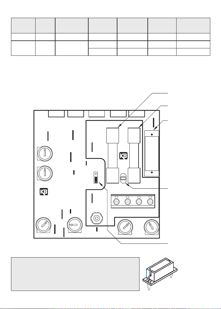
FIGURE 1 – CONTROL LAYOUT
(Illustrates Approximate Factory Setting of Trimpots and Jumper)
PLUG-IN HORSEPOWER RESISTOR
A Plug-in Horsepower Resistor® must be installed to match
the drive to the motor horsepower and armature current. See
Table 4, page 5 for the correct value. Plug-in Horsepower
Resistors® are stocked by your distributor.
CAUTION: Be
sure Plug-In
Horsepower
Resistor® is
inserted completely into
mating sockets.
F-
LINEARM
F2
DECEL
ACCEL
L1
L2
F+
B
T
180V90V
J2
F1
SW3
WHT
TB1
BLU
SW6
I1
P2
P3
P1
MAX MIN
L1
I2
L2
A+
A-
IRCL
ARMATURE FUSE
(CUSTOMER INSTALLED)
SEE TABLE 4, PAGE 5
LINE FUSE
(FACTORY INSTALLED)
PLUG-IN
HORSEPOWER RESISTOR
(CUSTOMER INSTALLED)
SEE TABLE 3, PAGE 5
CL LED
J2 IS INSTALLED
ON KBWM-240 ONLY
Page 6

4
FIGURE 2 – MECHANICAL SPECIFICATIONS (Inches / [mm])
3.00
[76.20]
2.31
[58.60]
6.81
[173.00]
TOP VIEW BOTTOM VIEW
DO NOT REMOVE
THESE (5) SCREWS.
REMOVE SCREWS TO OPEN CASE
0.09
3.69
[93.60]
1.84
R [2.30]
[46.80]
TM
ARI- RIVE
DC MOTOR
VD
SPEED CONTROL
5.28
6.36
[134.00]
[161.50]
ON
OFF
TM
80
60
70
90
100
50
30
40
(%) SPEED
0
10
20
Page 7

II. CONTROL SETUP
Remove the four (4) 6x32 screws (two on top and two on the bottom) from the enclosure. Slide
open the control by separating the front and rear covers. See Figure 2, page 4.
A. Plug-in Horsepower Resistor® – (Must be obtained from your distributor as a separate
part.) The Plug-in Horsepower Resistor® is designed to match the control and motor without having to recalibrate the IR Comp. and CL for most applications. (Note: For recalibration of IR Comp. and CL see Section VI E, F on pages 9 and 10.) Using the Plug-in
Horsepower Resistor® chart, choose the closest value based on motor horsepower
and/or armature current. (See Table 3.)
B. AC Line Fuse – The KBWM™ contains a 5-
Amp AC line fuse used to protect the control
against catastrophic failure. If fuse blows, the
control may be miswired, the motor is shorted
or grounded, or the speed control module is
defective. Replace with Littelfuse 326, Buss
ABC or equivalent. Note: Bypassing or eliminating the fuse will void warranty.
CAUTION: Most electrical codes require that
each ungrounded conductor contain fusing.
Separate branch fusing or circuit breakers may
be required on 208/230 VAC line.
C. Armature Fuse — The KBWM™ has provi-
sion for installing an armature fuse that helps
protect the motor and control from damage
due to overload. Armature fuses are 3 AG type
and are available from your distributor.
Note: An armature fuse must be installed or
control will not operate. Fuse value is calculated based on 1.7 times the DC current rating of the motor. See Table 4.
5
5
90 VDC 180 VDC
Motor Horsepower
Range
Approx.
Motor
Current
(DC Amps)
Fuse
Rating
(AC Amps)
1/100
1/50
1/30
1/20
1/15
1/10
1/8
1/6
1/4
1/3
1/50
1/25
1/15
1/10
1/8
1/5
1/4
1/3
1/2
3/4
0.1
0.2
0.3
0.5
0.7
1.0
1.3
1.7
2.5
3.3
1/5
3/10
1/2
3/4
1
11⁄2
2
3
4
TABLE 4 – ARMATURE FUSE
SELECTION CHART
9840
90 VDC 180 VDC
Motor Horsepower Range
Approx.
Motor Current
(DC Amps)
Plug-in Horsepower
Resistor® Value
(Ohms)
Individual
Plug-in Horsepower®
Resistor Part No.
1/3
1/100
1/50
1/30, 1/25
1/20
1/15, 1/12
1/10, 1/8, 1/6
1/4
1/50
1/25
1/15
1/10
1/6
1/4
1/2
3/4
0.1
0.2
0.35
0.5
0.8
1.3
2.5
3.3
1.0
0.51
0.35
0.25
0.18
0.1
0.05
0.035
9833
9834
9835
9836
9837
9838
9839
TABLE 3 – PLUG-IN HORSEPOWER RESISTOR® CHART
Note: Specific applications may require a different fuse value than indicated. This is based on
several factors such as ambient temperature.
Notes:
1. Motor horsepower and armature current must be specified in order to select correct Plug-in Horsepower Resistor®.
2. For motor horsepower not indicated, use the lower ohm value Plug-in Horsepower Resistor®.
Page 8

D. Jumper J2 is provided on Model KBWM-240 only
and is factory set to “180V” position. For stepdown operation (208/230 Volts AC line input and 090 Volts DC output), set J2 to the “90V” position.
See Figure 3.
III. MOUNTING
The KBWM™ is mounted via the rear cover
mounting strap. Before attempting to wire the
control, locate the mounting holes using the rear
cover as a template or use the dimensions as shown in the outline drawing. (See Figure 2,
page 4.) Be sure the control is mounted on a flat surface in a location where it will not be
exposed to contaminants such as water, metal chips, solvents or excessive vibration and/or
temperature extremes. Note: Allow adequate clearance around control to permit motor and
AC power cables to enter through the Bx knockouts on bottom of enclosure.
When mounting in an airtight enclosure, the air space should be large enough to provide adequate heat dissipation. It is recommended that an enclosure with minimum dimensions of 12”H
x 12”W x 6”D (300mm x 300mm x 150mm) be used. The maximum allowable ambient temperature at full rating is 50 ºC (122 ºF). Consult the Sales Department if more information is required.
Note: The KBWM™ can be oriented so that the AC power and motor wiring can be brought
in from the top of the control. Mount the rear cover so that the Bx knockouts are located on
the top by rotating the rear cover 180º. The front cover is then installed right side up using
the four (4) 6x32 screws previously removed from the top and bottom of the enclosure.
After wiring the front cover, install the mating rear cover with the four (4) 6x32 screws previously removed from the top and bottom of enclosures.
IV. WIRING
Be sure the AC power is “off” before wiring control. Read Safety Warning on page 1 before
attempting to use this control.
WARNING! To avoid erratic operation, do
not bundle AC line and motor wires with
potentiometer, voltage following, enable, inhibit or other
signal wiring. Use shielded cables on all signal wiring
over 12” (30 cm) – The shield should be earth grounded on the control side only. Wire the control in accordance with the National Electrical Code requirements
and other codes that may apply to your area.
A. AC Line – Wire the AC power to terminals L1 and
L2. Be sure that the control model corresponds to
the correct AC line input voltage. Model
KBWM–120 is for 115 VAC 50/60 Hz and model
KBWM–240 is for 208/230 VAC 50/60 Hz. See
Figure 4.
6
3.5
Maximum Tightening Torque
(in-lbs)
Supply Wire Gauge
Terminal Block
Designation
Connection
Designation
TB1 L1, L2, A+, A- 22 14
Minimum Maximum
TABLE 5 – TERMINAL BLOCK WIRING INFORMATION
FIGURE 4 – AC LINE & ARMATURE
CONNECTION
J2 Set for
180 Volt DC Motors
(Factory Setting)
J2 Set for
90 Volt DC Motors
(Step-Down)
FIGURE 3 – MOTOR VOLTAGE SELECTION
(MODEL KBWM-240 ONLY)
180V90V
180V90V
!
SW6
BLU
L2
L1
AC LINE
A+
+
M
-
MOTOR
TB1
A-
Page 9

Caution: If control is wired to a transformer, it is advisable to switch the secondary to disconnect power. If the primary is switched, additional snubber capacitors may have to be
added across terminals L1 and L2 to prevent power bridge damage.
Separate branch fusing or circuit breaker may be required on 208/230 VAC applications. (See
Section IV E, on page 8.)
B. Motor Armature – Wire the motor armature wires to terminals A+ and A-. Be sure the motor
voltage corresponds to the control voltage rating. See Figure 4, on page 6. Note: If motor
runs in opposite direction to what is required, turn power off and reverse armature leads.
WARNING! Do not wire a switch or relay in series with the armature leads.
Armature switching can cause catastrophic failure of motor and/or control. If
reversing or dynamic braking is required, consult the Sales Department.
C. Ground (earth) – Be sure to ground motor and control to green ground stud located between
the Bx knockouts. See Figure 7, on page 11.
D. Field (Shunt motors only) – Do not use F+ and F- terminals for any other motor type. The
KBWM™ control is primarily designed for permanent magnet (PM) motors. However, a shunt
motor can also be controlled by wiring the shunt field directly to the 1/4” quick-disconnect terminals located on the main speed control module. See Figures 5A and 5B for the F+ and Fterminal locations. Attach motor field using insulated 1/4” Q-D female terminals. For
Standard PM (2-wire) motors, the Field is not used.
CAUTION: Shunt-wound motors may be damaged if field remains connected without motor
rotating for an extended period of time.
7
MIN
I1
I2
T
L2
B
F+
F1
SW6
BLU
LINEARM
A+
L1
L2
A-
TB1
F2
F-
WHT
SW3
AC LINE
MOTOR
M
FIELD*
-
+
-
+
F+, L1
AC Line Voltage VAC Motor Voltage Field Voltage (Volts DC) Field Connection
115
115
208/230
208/230
208/230
0 – 90
0 – 90
0 – 180
0 – 180
0 – 90
100
50
200
100
100
F+, F-
F+, L1
F+, F-
F+, L1
TABLE 6 – FIELD CONNECTION (Shunt Wound Motors Only)
FIGURE 5A – FULL VOLTAGE FIELD
MIN
I1
I2
T
L2
B
F+
F1
SW6
BLU
LINEARM
A+
L1
L2
A-
TB1
F2
F-
WHT
SW3
AC LINE
MOTOR
M
FIELD*
+
-
-
+
FIGURE 5B – HALF VOLTAGE FIELD
*Shunt motors only
!
J2
180V90V
J2
180V90V
Page 10

E. Fusing – As indicated in Section IIB, the KBWM™ contains a single AC line fuse on
208/230 VAC applications. In the USA and other countries where the 208/230 volt is
derived from two (2) “hot” leads, both AC lines should be connected to a separate dual circuit breaker. Do not fuse neutral or grounded connections.
F. AC Line Switch – The KBWM™ contains a double pole AC line switch which opens both
legs of the AC line.
V. OPERATION
After wiring is complete, recheck connections to be sure they are correct. Also be sure correct armature fuse and Plug-in Horsepower Resistor® are installed. Turn main power on.
Internal lamp in power switch should be lighted indicating control is receiving AC line voltage.
Gradually increase main speed dial setting. Motor should rotate in proportion to dial setting.
Note: if motor runs in opposite direction to what is required, turn power off and reverse armature leads.
WARNING! If control is operated with cover off, be sure to wear safety glasses
and use insulated tools if any adjustments are to be made.
CL LED – A red light-emitting diode (LED) can be found on the speed control PC board. It
lights when the current limit circuit activates, indicating an overload condition. This is normal
when the motor accelerates to full speed or when a transient peak load condition exists.
However, if the LED lights continuously, a severe overload condition may exist. A DC ammeter should be installed in series with either armature lead to observe motor current during
actual operation. (See Safety Warning on page 1.) If the actual DC current exceeds the
motor rating, a higher horsepower motor should be used. If actual current is equal to or less
than the rated motor current, the CL adjustment may be incorrect, or the Plug-in Horsepower
Resistor® value may be too high. Refer to the CL trimpot adjustment procedure and the
Plug-in Horsepower Resistor® chart on page 5.
VI. TRIMPOT ADJUSTMENTS AND CONTROL FUNCTIONS
WARNING!
If adjustments are made under power, insulated adjustment tools must
be used and eye protection must be worn.
The KBWM™ has been factory adjusted to provide 0 - full speed using the speed control
knob. Minimum (MIN) and Maximum (MAX) speed trimpots are provided to change the
speed settings. The acceleration (ACCEL) trimpot is provided to allow for a smooth start over
an adjustable time period each time the AC power is applied or the Main Speed
Potentiometer is rotated. The DECEL trimpot controls the amount of ramp-down time when
the Main Speed Potentiometer is adjusted to a lower speed. The Current Limit (CL, or torque
output) adjustment is factory set to approximately 1.5 times the motor rating. The IR
Compensation (IR) is factory adjusted to provide excellent motor regulation under normal
operation.
Note: For the IR Comp. and CL trimpot settings to be correct, the proper Plug-in Horsepower
Resistor® must be installed. (See Table 3 on page 5.) Do not attempt to change the settings of the trimpots unless absolutely necessary since they are factory adjusted to near optimum settings.
The following procedure, presented in order of adjustment sequence, should be used when
readjusting all trimpot functions:
8
!
!
Page 11

A. Acceleration Start – The ACCEL is
factory set at approximately 2 seconds.
To readjust to different times, set the
knob to the desired position as shown
in Figure 6A.
B. Deceleration – The DECEL is factory
set to provide a ramp-down time of 2
seconds. To change the ramp-down
time, adjust the DECEL trimpot as indicated in Figure 6B.
C. Minimum Speed Adjustment – If a
higher than zero minimum speed is
needed, readjust the minimum speed
by turning the speed control knob to
zero setting (full CCW position). Then
adjust the MIN speed trimpot to the
desired setting.
Note: The minimum speed adjustment
will affect the maximum speed setting.
Therefore, it is necessary to readjust
the maximum speed after the minimum
speed.
D. Maximum Speed Adjustment – Turn
Speed Control Knob to full speed (full
CW position). Adjust MAX speed trimpot to new desired setting.
Note: Do not attempt to adjust the maximum speed above the rated motor RPM
since unstable motor operation may
occur. For moderate changes in the
maximum speed, there will only be a
slight effect on the minimum speed setting.
E. Current Limit (CL/Torque Adjustment) – CL circuitry is provided to protect the motor
and control against overloads. The CL also limits the inrush current to a safe level during
startup. The CL is factory set to approximately 1.5 times the full load rating of the motor.
(CL trimpot is nominally set to approximately 65% of full CW rotation.) Note: Proper size
Plug-in Horsepower Resistor® must be installed.
To set the CL to factory specifications adjust as follows:
1. Set speed control knob at approximately 30 - 50% CW rotation. Set CL trimpot to full
CCW position.
2. Connect a DC ammeter in series with the armature lead.
3. Lock shaft of motor (be sure CL pot is in full CCW position). Apply power and rotate CL
pot CW until DC ammeter reads 1.5 times motor rating. (Do not exceed 2 times motor
rating.) Do not leave motor in locked rotor position for more than a few seconds or damage may occur.
Note: The CL LED will illuminate when the control is in current limit.
9
FIGURE 6A – ACCEL TRIMPOT ADJUSTMENT
FIGURE 6B – DECEL TRIMPOT ADJUSTMENT
FACTORY SETTING 2 SEC.
RAPID
0.2 SEC.
SLOW
10 SEC.
ACCEL
5 SEC.
8 SEC.
FACTORY SETTING 2 SEC.
RAPID
0.2 SEC.
SLOW
10 SEC.
DECEL
5 SEC.
8 SEC.
Page 12

Note: If only an AC ammeter is available, it can be installed in series with AC input
line. Follow above instructions; however, set AC amperage at 0.75 motor rating.
F. IR Compensation Adjustment – IR compensation is provided to improve load regulation.
If the load presented to the motor does not vary substantially, the IR adjustment may be
set at a minimum level (approximately 1/4 of full setting). The control is factory adjusted
to approximately 3% regulation. If superior performance is needed (less than 1% speed
change of base speed from 0 - full load), then the IR Comp. should be adjusted as follows:
Note: Excessive IR Comp. will cause control to become unstable, which causes motor
cogging.
1. Set IR Comp. trimpot at approximately 25% of CW rotation. Run motor unloaded at
approximately 1/3 speed and record RPM.
2. Run motor with maximum load and adjust IR Comp. trimpot so that the motor speed
under load equals the unloaded speed per step 1.
3. Remove load and recheck unloaded RPM. If unloaded RPM has shifted, repeat procedure for more exact regulation.
The control is now compensated to provide minimal speed change under large variations of applied load.
10
Page 13

11
PLUG-IN
FIGURE 7 – INTERNAL CONNECTION DIAGRAM
LINE FUSE
ARMATURE FUSE
(FACTORY INSTALLED)
(CUSTOMER INSTALLED)
(CUSTOMER INSTALLED)
HORSEPOWER RESISTOR
F-
LINEARM
L1
CL LED
TB1
A-
A+
F2
L2
L1
F1
WHT
SW3
L2
DECEL
J2
180V90V
B
F+
T
ACCEL
BLU
SW6
I1
P2
I2
P1
P3
J2 IS INSTALLED
ON KBWM-240 ONLY
IRCL
MAX MIN
GROUND SCREW
ENCLOSURE BASE
BLUE (L2)
WHITE (L1)
WHITE (SW3)
BLUE (SW6)
MAIN SPEED POTENTIOMETER
ORANGE (P2)
WHITE (P1)
ON/OFF SWITCH
ENCLOSURE COVER
VIOLET (P3)
Page 14

– NOTES –
12
Page 15

– NOTES –
13
Page 16

VII. LIMITED WARRANTY
For a period of 18 months from the date of original purchase, KB Electronics, Inc. will repair
or replace, without charge, devices which our examination proves to be defective in material
or workmanship. This warranty is valid if the unit has not been tampered with by unauthorized
persons, misused, abused, or improperly installed and has been used in accordance with the
instructions and/or ratings supplied. The foregoing is in lieu of any other warranty or guarantee, expressed or implied. KB Electronics, Inc. is not responsible for any expense, including
installation and removal, inconvenience, or consequential damage, including injury to any person, caused by items of our manufacture or sale. Some states do not allow certain exclusions
or limitations found in this warranty and therefore they may not apply to you. In any event, the
total liability of KB Electronics, Inc., under any circumstance, shall not exceed the full purchase
price of this product. (rev 2/2000)
(A40275) – Rev. C – 6/2001
KB Electronics, Inc.
12095 NW 39th Street, Coral Springs, FL 33065-2516 • (954) 346-4900 • Fax (954) 346-3377
Outside Florida Call TOLL FREE (800) 221-6570 • E-mail – info@kbelectronics.com
www.kbelectronics.com
 Loading...