

Page 1
INSTALLATION AND OPERATION MANUAL
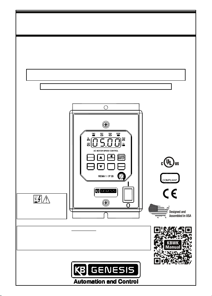
KBWK-23D
ADJUSTABLE FREQUENCY DRIVE FOR 3-PHASE AC MOTORS
NEMA 1 / IP 20 ENCLOSURE
MULTI-FUNCTION KEYPAD WITH 4-DIGIT LED DISPLAY
• Simplified Group Programming • 8 LED Status Indicators
Subfractional thru 1/2 HP 3-Phase AC and 1-Phase PSC* Induction Motors
Operates from 115 and 208/230 Volt 50/60 Hz AC Line Input
*Operation with
PSC motors requires
factory programming.
SEE
SAFETY WARNING
ON PAGE 4
This Manual Covers Model KBWK-23D (Part No. 8860)
AC Line Input Voltage Setting: The drive is factory set for 208/230 Volt
AC Line input. For 115 Volt AC Line input, see Section 10 on page 18.
Motor Frequency Setting: The drive is factory set for 60 Hz Motors.
For 50 Hz Motors, see Section 6.1 on page 12.
Rated for 208 – 230 Volt 50 and 60 Hz
Variable Speed / Soft Start
with Electronic Motor Overload Protection
STOP
IMPORTANT
RUN
FWD
REV
RESET
JOG
READ
ENTER
RoHS
KBWK SERIES
Copyright © 2014
KB Electronics, Inc.
(see back cover)
The QR Code link
to this manual is also
located on the inside of
the drive cover.
Page 2

TABLE OF CONTENTS
Section Page
1 SAFETY WARNING, CE INFORMATION, AND UL NOTICE...............................4
2 QUICK-START INSTRUCTIONS ..........................................................................5
3 FAMILIARIZING YOURSELF WITH THE DRIVE .................................................6
4 ELECTRICAL RATINGS AND SPECIFICATIONS...............................................9
5 INTRODUCTION .................................................................................................10
5.1 Standard Features ..................................................................................11
5.2 Performance Features............................................................................11
5.3 Selectable Jumper (J3) ..........................................................................11
5.4 Protection Features ................................................................................12
5.5 Customization for OEMs........................................................................12
6 IMPORTANT PROGRAMMING INFORMATION ................................................ 12
6.1 50 Hz Motors ...........................................................................................12
6.2 Motor Current Setting ............................................................................12
6.3 Reset Drive..............................................................................................12
7 IMPORTANT APPLICATION INFORMATION ....................................................13
7.1 Motor with External Fan Cooling ..........................................................13
7.2 Electronic Motor Overload Protection..................................................14
8 MOUNTING .........................................................................................................14
9 REMOVING AND INSTALLING THE COVER ....................................................16
9.1 Removing the Cover...............................................................................16
9.2 Installing the Cover ................................................................................16
10 SETTING AC LINE INPUT VOLTAGE SELECTION JUMPER J3 .....................18
11 RECONDITIONING THE BUS CAPACITORS ....................................................18
12 ELECTRICAL CONNECTIONS...........................................................................18
12.1 AC Line Input and Ground .....................................................................20
12.2 Motor and Ground ..................................................................................20
12.3 AC Line Input Fusing .............................................................................20
13 HIGH VOLTAGE DIELECTRIC WITHSTAND TEST (HI-POT TEST) ................20
14 DRIVE OPERATION............................................................................................22
14.1 Start-Up Procedure.................................................................................22
14.2 Keypad Description ................................................................................22
14.3 Flow Charts for Important Programming Functions ...........................23
15 4-DIGIT DISPLAY READOUT CODES ............................................................... 29
16 PROGRAMMABLE FUNCTIONS LIST...............................................................31
Appendix A: Keypad/Potentiometer Set Frequency Select (Shortcut) .................36
Appendix B: Changing Operating Sense of the FWD/REV Key (Shortcut) ..........37
Appendix C: Reset and Memory Functions .............................................................38
LIMITED WARRANTY.................................................................................. Back Cover
2
Page 3

TABLE OF CONTENTS (CONTINUED)
Table Page
1 Descriptions of 4-Digit Display, LEDs, Keys, and Potentiometer ...................7
2 Electrical Ratings.................................................................................................9
3 General Performance Specifications .................................................................9
4 Terminal Block TB1 Wire and Tightening Torque Specifications .................19
5 DC Hi-Pot Tester Setup Information.................................................................21
6 Digital Readout Codes.......................................................................................29
Figure Page
1 Front Panel Layout ..............................................................................................6
2 Drive Layout .........................................................................................................8
3 Maximum Allowed Motor Torque vs. Speed....................................................13
4 Open Ventilated Motor with External Cooling .................................................13
5 Mechanical Specifications ................................................................................15
6 Cover Positioned On Top of Case....................................................................17
7 AC Line Input Voltage Selection Jumper J3.................................................... 18
8 AC Line Input, Motor, and Ground Connections ............................................19
9 Typical Hi-Pot Test Setup..................................................................................21
10 Flow Chart to Program Motor Nameplate Current ..........................................23
11 Flow Chart to Program Set Frequency ............................................................24
12 Flow Chart to Program Rated Motor Frequency.............................................24
13 Flow Chart to Program Accel Time ..................................................................25
14 Flow Chart to Program Display for Custom Units ..........................................26
15 Flow Chart to Program Display ........................................................................27
16 Flow Chart to Add Parameters to Basic Display............................................. 27
17 Flow Chart to Program Passcode Enable and Set A Passcode ....................28
18 Function No. Description ..................................................................................31
ITEMS INCLUDED IN THIS PACKAGE
Description Part No.
KBWK Drive 8860
Installation and Operation Manual A40197
Hardware Bag: Jumper J3 (to Set the Drive for 115 Volt AC Line Input),
Extra 6-32 X 1-1/4" Cover Screw, and two Universal Bushings.
Mounting Template A42326
Warranty Registration Card A40101
F36875
3
Page 4
1 SAFETY WARNING, CE INFORMATION, AND UL NOTICE
SAFETY WARNING
Definition of Safety Warning Symbols
Electrical Hazard Warning Symbol: Failure to observe this warning could
result in electrical shock or electrocution.
Operational Hazard Warning Symbol: Failure to observe this warning could
result in serious injury or death.
This product should be installed and serviced by a qualified technician,
electrician, or electrical maintenance person familiar with its operation and the
hazards involved. Proper installation, which includes electrical connections, fusing or
other current protection, and grounding, can reduce the chance of electrical shocks,
and/or fires, in this product or products used with this product, such as electric
motors, switches, coils, solenoids, and/or relays. Do not use this drive in an
explosion-proof application. Eye protection must be worn and insulated adjustment
tools must be used when working with drive under power. This product is constructed
of materials (plastics, metals, carbon, silicon, etc.) which may be a potential hazard.
Proper shielding, grounding, and filtering of this product can reduce the emission of
radio frequency interference (RFI) which may adversely affect sensitive electronic
equipment. It is the responsibility of the equipment manufacturer and individual
installer to supply this Safety Warning to the ultimate end user of this product.
(SW 1/2006)
The drive contains electronic Start/Stop circuits, which can be used to start and stop
the drive. However, these circuits are never to be used as safety disconnects since
they are not fail-safe. Use only the AC Line for this purpose.
Be sure to read and follow all instructions carefully. Fire and/or electrocution can
result due to improper use of this product.
CE INFORMATION
This product complies with all CE directives pertinent at the time of
manufacture. Contact our Sales Department for Declaration of Conformity.
Installation of a CE approved RFI filter is required. Additional shielded cable and/or
AC Line cables may be required.
Note: In order for this drive to meet CE requirements, a separate CE approved filter
must be installed.
UL NOTICE
115 Volt Drives:
Suitable for use on a circuit capable of delivering not more than
5 kA RMS symmetrical Amperes. 115 Volts maximum. Use copper conductors rated
75 °C. Suitable for operation in a maximum surrounding air temperature of 40 °C.
230 Volt Drives: Suitable for use on a circuit capable of delivering not more than
5 kA RMS symmetrical Amperes. 230 Volts maximum. Use copper conductors rated
75 °C. Suitable for operation in a maximum surrounding air temperature of 40 °C.
4
Page 5

2 QUICK-START INSTRUCTIONS
2.1 REMOVE THE COVER
Remove the cover to setup and wire the drive. See Section 9.1 on page 16.
2.2 MOUNT THE DRIVE
See Section 8 on pages 14 and 15.
2.3 AC LINE INPUT SELECTION
The drive is factory set for 208/230 Volt AC Line input (Jumper J3 not installed). Install
the supplied jumper to set the drive for 115 Volt AC Line input. See Section 10 on
page 18. Note: The drive will operate 230 Volts AC motors with 115 Volt AC line
input.
2.4 AC LINE INPUT, MOTOR, AND GROUND CONNECTIONS
At Terminal Block TB1, wire the AC Line input to "L1 and "L2"; the ground wire(s) to
"GND"; and the motor to "U", "V", and "W". See Section 12 on pages 18 – 20.
2.5 INSTALL THE COVER
After the drive has been setup, mounted, and wired, install the cover. See Section 9.2
on page 16.
2.6 GFCI OPERATION
Allows the drive to operate with Ground Fault Circuit Interruption circuit breakers and
outlets. Use Function 0.04 to program for GFCI operation. (May increase audible
motor noise.)
2.7 SELECTING SET FREQUENCY ADJUSTMENT METHOD (SHORTCUT)
The Keypad/Potentiometer shortcut allows the selection of the source for adjusting the
Set Frequency without requiring reprogramming the drive. The Keypad is factory
programmed as the default for adjusting the Set Frequency. To use the Built-In
Potentiometer to adjust Set Frequency, press both Up and Down Keys simultaneously
for 4 seconds. To switch back to using the Keypad to adjust Set Frequency, press
both Up and Down Keys simultaneously for 4 seconds. See Appendix A on page 36.
2.8 CHANGING OPERATING SENSE OF THE FWD/REV KEY (SHORTCUT)
For applications that require changing motor direction, the sense of the FWD/REV
Key can be changed, without requiring reprogramming the drive or reversing any two
motor leads. Put the drive in the Stop Mode and press and hold the FWD/REV Key for
5 seconds. The forward direction will now be "reverse" and the reverse direction will
now be "forward". See Appendix B on page 37.
2.9 MOTOR FREQUENCY SELECTION
The drive is factory set to operate 60 Hz motors (Function 0.00 set to "0000"). For 50
Hz motors, set Function 0.00 to "0001". See Flow Chart (Figure 12) on page 24.
5
Page 6
3 FAMILIARIZING YOURSELF WITH THE DRIVE
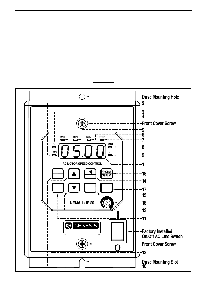
The drive has a 4-Digit LED Display, 8 Status LEDs, a Multi-Function Keypad, a builtin potentiometer, and a factory installed On/Off AC Line Switch. See Figure 1, below,
and Table 1 on page 7. Remove the cover to access Jumper J3 terminals (AC Line
Input Voltage Selection) and Terminal Block TB1 (AC Line input, Motor, and Ground
connections). See Figure 2 on page 8.
Mounting: Section 8 on pages 14 and 15.
Removing and Installing the Cover: Section 9 on pages 16 and 17.
AC Line Input Voltage Selection Jumper J3: Section 10 on page 18.
Electrical Connections: Section 12 on pages 18 – 20.
Drive Operation: Section 14 on pages 22 – 28.
FIGURE 1
FRONT PANEL LAYOUT (SEE TABLE 1 ON PAGE 7 FOR DESCRIPTIONS)
RUN
STOP
RESET
FWD
REV
KBWK SERIES
JOG
READ
ENTER
6
Page 7
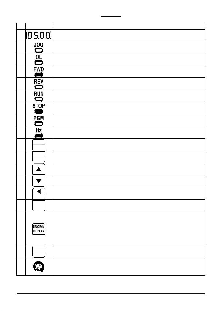
DESCRIPTIONS OF 4-DIGIT DISPLAY, LEDs, KEYS, AND POTENTIOMETER
TABLE 1
No. Feature Description
1
2
3
4
5
6
7
8
9
10
11
12
13
14
15
RUN
STOP
FWD
REV
RESET
JOG
4-Digit Display: Provides readout of drive status, functions, and
faults.
JOG LED: Indicates that the drive is in Jog Mode.
OL LED: Indicates that the drive is in Overload.
FWD LED: Indicates that the drive is set for Forward Direction.
REV LED: Indicates that the drive is set for Reverse Direction.
RUN LED: Indicates that the drive is in the Run Mode.
STOP LED: Indicates that the drive is in Stop Mode.
PGM LED: Indicates that the drive is in Program Mode.
Hz LED: Indicates that the display is set to show Drive Output
Frequency (in Hz).
RUN / STOP Key: Starts and stops the drive.
FWD/REV Key: Changes motor direction.
Up Key:* Increases Output Frequency, Set Frequency, Function
Number Value, and Code setting. Also used as shortcut key.*
Down Key:* Decreases Output Frequency, Set Frequency, Function
Number Value, and Code setting. Also used as shortcut key.*
Left Shift / Reset Key: Moves the changeable digit or Resets the
drive after a fault has cleared.
JOG Key: Provides a fixed speed.
PROGRAM / DISPLAY Key: Puts the drive into Program Mode or
Display Mode. If pressed while Set Frequency is displayed, the
16
previously entered Function Number will be shown. If pressed while
Function Number is displayed, the Set Frequency will be shown.
When more than one display function is enabled, the key is used to
toggle between displays.
17
READ
ENTER
READ / ENTER Key: Reads or Enters a Function Value or Code
Setting.
Potentiometer:* Sets the Drive Output Frequency in lieu of the
18
Keypad. To change the Keypad for Potentiometer Operation, set
Function 2.00 to "0001".
*Adjustment of Set Frequency can be switched between the built-in potentiometer and
the keypad by pressing both Up and Down Keys simultaneously for 4 seconds.
See Appendix A on page 36.
7
Page 8
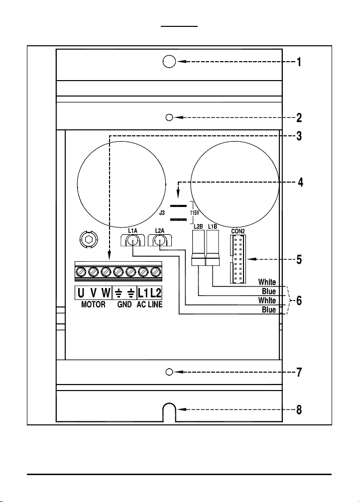
DRIVE LAYOUT (SEE DESCRIPTIONS BELOW)
FIGURE 2
(SHOWN WITH COVER REMOVED)
TB1
1. Drive mounting hole. 2. Cover mounting hole. 3. TB1 for AC Line Input, Motor, and
Ground connections. See Sections 12.1 and 12.2 on page 20. 4. J3 for AC Line Input
voltage selection (factory set for 208/230 Volt AC Line Input). See Section 10 on page
18. 5. CON2 for Keypad interface connector. 6. To factory installed On/Off AC Line
Switch. 7. Cover mounting Hole. 8. Drive mounting slot.
8
Page 9

4 ELECTRICAL RATINGS AND SPECIFICATIONS
TABLE 2
ELECTRICAL RATINGS
Maximum
Horsepower
(HP (kW))
0.5 (0.37)
AC Line Input Output Net Wt.
Volts AC
(50/60 Hz)
115 1 8.8 15 2.2
208/230 1 6.0 10 2.4
Phase
(Ø)
Maximum
Current
(Amps AC)
Fuse or
Circuit
Breaker
Rating
(Amps)
Maximum
Continuous
Load Current
(RMS Amps)
Maximum
Voltage
(Volts AC)
230 1.72 0.78
lbs kg
TABLE 3
GENERAL PERFORMANCE SPECIFICATIONS
Description Specification
115 Volt AC Line Input Voltage Operating Range (Volts AC) 115 (±15%) —
208/230 Volt AC Line Input Voltage Operating Range (Volts AC)
Maximum Load (% Current Overload for 2 Minutes) 150 —
Switching Frequency (Function 3.17) (kHz) 8, 10, 12 8
Output Frequency Resolution (Hz) 0.06 —
Minimum Operating Frequency at Motor (Hz) 1 —
Acceleration Time (Function 3.03) (Seconds) 0.1 – 180.0 1.5
Deceleration Time (Function 3.04) (Seconds) 0.3 – 180.0 1.5
Speed Range (Ratio) 60:1 —
Speed Regulation (30:1 Speed Range, 0 – Full Load)
(% Base Speed)
Overload Protector Trip Time for Stalled Motor (Seconds) 6 —
AC Line Input Undervoltage/Overvoltage Trip Points
For 115 Volt AC Line (±5%) (Volts AC)
AC Line Input Undervoltage/Overvoltage Trip Points
for 208/230 Volt AC Line (±5%) (Volts AC)
Operating Temperature Range (°C / °F)
Operating Humidity Range (% Relative, Non-Condensing) 0 – 95 —
Storage Temperature (°C / °F)
1
2
2
208 (-15%) /
230 (+15%)
2.5 —
76 – 141 —
151 – 282 —
0 – 40 /
32 – 104
-25 – +85 /
-13 – +185
Factory
Setting
208/230
—
—
Notes: 1. Dependent on motor performance. 2. Do not operate the drive outside the
specified AC line input voltage operating range.
9
Page 10

5 INTRODUCTION
Thank you for purchasing the KBWK Digital AC Drive. KB Electronics, Inc. is
committed to providing total customer satisfaction by providing quality products that
are easy to install and operate.
The KBWK drive is housed in NEMA 1 / IP 20 enclosure. It is designed to operate
subfractional through 1/2 HP 208 – 230 Volt 50 and 60 Hz 3-phase AC and PSC
induction motors.
1
Flux Vector Control provides high torque, low noise, and excellent
load regulation over a wide speed range. Adjustable linear acceleration and
deceleration make the drive suitable for soft-start applications.
Due to its user-friendly design and simple to use and understand instruction manual,
the KBWK is easy to install and operate. Setting the drive to specific applications is
accomplished using the Multi-Function Keypad, which provides easy operation and
programming of the drive. To facilitate programming, all similar functions are
presented in common groups.
The 4-Digit Display provides readout of drive operation, programming functions, and
displays Output Frequency, Motor RPM, Output Current, Output Voltage, Bus Voltage,
Function Codes and Values, Fault Codes, and Custom Units. The 8 LEDs provide
indication of the drive's operational status. The on-board memory can store a user-
defined custom program.
Main Features: Adjustable RMS Current Limit and I2t Motor Overload Protection.2
Flux Vector Control with Static Auto-Tune provides high torque and excellent load
regulation over a wide speed range. Power Start™ delivers over 200% motor torque
to ensure startup of high frictional loads and programmable Injection Braking provides
rapid motor stop. Electronic Inrush Current Limit (EICL™) eliminates harmful AC Line
inrush current, allowing the drive to be AC Line switched. The drive is suitable for
machine or variable torque (HVAC) applications. A terminal block is provided to
facilitate AC line input, motor, and ground connections. A selectable jumper (supplied)
allows the drive to be set for 115 or 208/230 Volt AC Line input. The drive includes a
built-in potentiometer and an illuminated On/Off AC Line Switch. The drive also
contains a programmable passcode feature, which can be used to prevent tampering
or unauthorized changes to programmed functions and settings. Adjustment of Set
Frequency can be switched, without requiring programming, between the built-in
potentiometer and the keypad using shortcut keys.
Notes: 1. PSC motor operation requires OEM software – contact our Sales
Department. 2. UL approved as an electronic overload protector for motors.
10
Page 11

5.1 STANDARD FEATURES
Simplified Programming: Programmable functions are organized into easy-to-
understand intuitive groups. Factory programming available.
Current and Torque Limit: Current and torque limiting in motoring and braking
quadrants. Automatic extending of Accel and Decel eliminates tripping caused by
rapid acceleration and deceleration of high inertial loads. Spin Start operation
catches a spinning load and allows a smooth return to the set motor speed.
4-Digit Display and 8 LEDs: Provide readout of programming functions and
indication of the drive's operational status.
Easy-to-Use Multi-Function Keypad: Facilitates programming the drive.
Dual Voltage AC Line Input Operation: The drive operates from 115 and 208/230
Volt 50/60 Hz AC Line input. See Section 10 on page 18.
Built-In Potentiometer: Adjusts set motor speed in lieu of the keypad.
Factory Installed On/Off AC Line Switch: The switch illuminates when power is
applied to the drive and the switch is in the on position.
GFCI OPERATION: Tripless operation with GFCI software allows the equipment to
operate with Ground Fault Circuit Interruption circuit breakers or outlets.
(May increase audible motor noise.) See Function 0.04.
Passcode: Programamble passcode feature can be used to prevent tampering or
unauthorized changes to programmed functions and settings.
Custom Programming for OEM Applications: Provides out-of-the-box operation.
5.2 PERFORMACE FEATURES
High Performance Sensorless Flux Vector Control with Static Auto Tuning:
Provides excellent speed regulation with high torque loads throughout the entire
speed range. Auto energy savings at light loads. Smooth motor torque.
Library of Advanced Algorithms: Custom programming and PLC functions for
OEM applications.
Power Start™: Provides more than 200% starting torque, which ensures startup of
high frictional loads.
Speed Range: Full torque control over a 60:1 speed range.
5.3 SELECTABLE JUMPER (J3)
J3 (115V): The drive is factory set for 230 Volt AC Line input (J3 not installed). For
115 Volt AC Line input, install Jumper J3 (supplied). See Section 10 on page 18.
11
Page 12

5.4 PROTECTION FEATURES
Motor Overload (I
2
t) with RMS Current Limit: Provides motor overload protection
which prevents motor burnout and eliminates nuisance trips. UL approved as an
electronic overload protector for motors. See Section 6.2 below.
Electronic Inrush Current Limit (EICL™): Eliminates harmful inrush AC Line
current during startup and allows rapid start with AC Line.
Short Circuit: Shuts down the drive if a short circuit occurs at the motor (phase-to-
phase).
Regeneration: Eliminates nuisance tripping due to bus overvoltage caused by rapid
deceleration of high inertial loads.
Undervoltage and Overvoltage: Shuts down the drive if the AC Line input voltage
goes below or above the operating range.
MOV Input Transient Suppression: Protects the drive components against
damaging voltage spikes on the AC line.
Microcontroller Self Monitoring and Auto-Reboot.
5.5 CUSTOMIZATION FOR OEMs
Custom Software: The drive is preset and ready to use "out-of-the-box". Custom
front panels are also available. The drive can be factory programmed for
applications that require special switching, timing, PLC functions, and GFCI
operation. Contact our Sales Department.
6 IMPORTANT PROGRAMMING INFORMATION
6.1 50 Hz MOTORS
This drive is factory programmed to operate 60 Hz motors. For 50 Hz motors, set
Function 0.00 to "0001" (50 Hz). See Flow Chart (Figure 12) on page 24.
6.2 MOTOR CURRENT SETTING
The motor current is factory set to the maximum drive rating, as shown in Table 2 on
page 9. In order for the Motor Overload Protection to operate properly, the drive must
be reprogrammed to the actual Motor Nameplate Current (see Function 0.01). Do not
exceed the drive's maximum current rating. See Flow Chart (Figure 10) on page 23.
6.3 RESET DRIVE
For Factory Settings, set Function 5.06 to "1111". For OEM Custom Program, set
Function 5.06 to "1010". For User Custom Program set Function 5.06 to "1100".
See Appendix C on pages 38 and 39.
12
Page 13
7 IMPORTANT APPLICATION INFORMATION
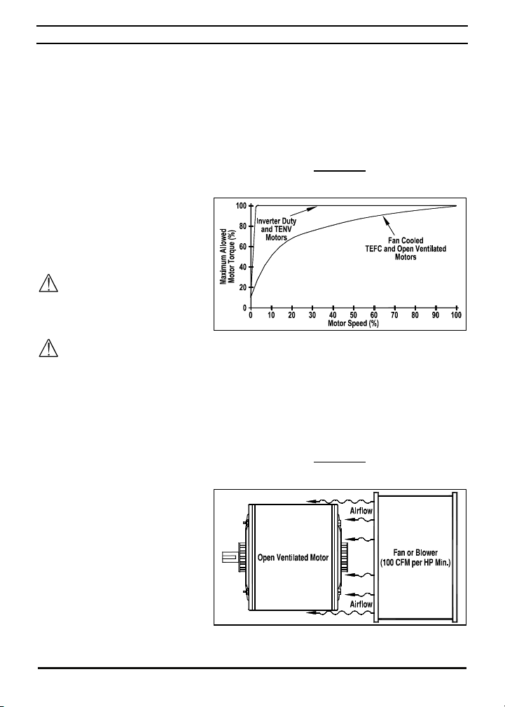
7.1 MOTOR WITH EXTERNAL FAN COOLING
Most totally enclosed fan-cooled (TEFC) and open ventilated 3-phase AC induction
motors will overheat if used beyond a limited speed range at full torque. Therefore, it
is necessary to reduce motor load as speed is decreased.
Note: Some fan-cooled motors can be used over a wider speed range. Consult the
motor manufacturer for details.
Inverter duty and most Totally
Enclosed Non-Ventilated (TENV)
motors can provide full rated
torque over an extended speed
range without overheating. See
Figure 3.
It is recommended that the
drive be used with Inverter
Duty or TENV motors.
WARNING! Some motors have low speed characteristics, which cause
overheating and winding failure under light load or no load conditions. If the motor is
operated in this manner for an extended period of time, it is recommended that the
unloaded motor current be checked from 2 – 15 Hz (60 – 450 RPM) to ensure motor
current does not exceed the nameplate rating. If the motor current exceeds the
nameplate rating, the Boost Value may have to be decreased (see Function 3.16).
Do not use motor if the motor current exceeds the nameplate rating.
If external cooling is provided,
open ventilated motors can also
achieve an extended speed range
at full rated torque. A fan or
blower with a minimum of 100
CFM per HP is recommended.
Mount the fan or blower so the
motor is surrounded by the
airflow. See Figure 4.
MOTOR TORQUE VS. SPEED
OPEN VENTILATED MOTOR
WITH EXTERNAL COOLING
FIGURE 3
MAXIMUM ALLOWED
FIGURE 4
13
Page 14

7.2 ELECTRONIC MOTOR OVERLOAD PROTECTION
The drive contains Modified I
2
t Overload Protection (UL approved as an overload
protector for motors). Part of this function consists of a Current Limit (CL) circuit,
which limits the drive current to a preset level of 160% of the Motor Nameplate Rated
Current setting. The factory setting for Motor Nameplate Current (Function 0.01)
is the drive rated current, as shown in Table 2 on page 9, which must be set to
the actual motor nameplate current (see Important Programming Information
(Section 6 on page 12).
Standard I
2
t is undesirable because it causes nuisance tripping. It allows a very high
motor current to develop and will turn the drive off after a short period of time. KB's
RMS Current Limit Circuit avoids this nuisance tripping while providing maximum
motor protection.
If the motor is overloaded to 120% of the Motor Nameplate Rated Current, the I
2
t
Timer starts. If the motor continues to be overloaded at the 120% level, the timer will
shut down the drive after 30 minutes. If the motor is overloaded to 160% of full load,
the drive will trip in 6 seconds.
8 MOUNTING
Use the supplied mounting template to facilitate locating the holes to mount the drive.
It is recommended that the drive be mounted vertically on a flat surface with adequate
ventilation. Leave enough room below the drive to allow for AC Line, motor
connections, and any other connections that are required. Care should be taken to
avoid extreme hazardous locations where physical damage can occur. When
mounting the drive in an enclosure, the enclosure should be large enough to allow
proper heat dissipation so that the ambient temperature does not exceed 40 °C
(104 °F) at full rating. See Figure 5 on page 15.
WARNING! DO NOT USE THIS DRIVE IN AN EXPLOSIVE
ENVIRONMENT. AN EXPLOSION CAN CAUSE SERIOUS OR FATAL INJURY.
THIS DRIVE IS NOT EXPLOSION PROOF.
14
Page 15

RUN
STOP
FWD
MECHANICAL SPECIFICATIONS (INCHES/mm)
FIGURE 5
0.200
2X Ø
5.08
RESET
READ
KBWK SERIES
1.40
35.6
3.580
90.9
3.925
99.7
JOG
ENTER
REV
5.370
0.345
8.76
0.875
22.2
5.660
144136
2X
4.40
112
6.060
154
0.125
3.18
2.00
50.8
15
Page 16

9 REMOVING AND INSTALLING THE COVER
The cover must be removed to set up the drive. See Section 9.1 for instructions on
removing the cover. See Section 9.2 for instructions on installing the cover.
AC Line Input Voltage Selection Jumper J3 Setting: See Section 10 on page 18.
AC Line, Motor, and Ground Connections: See Section 12 on pages 18 – 20.
WARNING! Disconnect the main power before removing or installing the
cover.
WARNING! After disconnecting the main power to the drive, wait at least
30 seconds before removing the cover.
WARNING! To prevent accidental contact with high voltage, it is required
that the cover be properly installed onto the drive after all wiring and setup is
complete. It offers protection against electric shock which limits the potential
liability to the equipment manufacturer and installer.
9.1 REMOVING THE COVER
Remove the two screws on the cover and slide it off the drive's base. Be careful not to
separate the wires from the drive to the cover's On/Off AC Line Switch and the
Keypad's interface ribbon cable.
To facilitate wiring the drive, place the cover on top of the case, as shown in Figure 6
on page 17.
9.2 INSTALLING THE COVER
After setting up the drive, install the cover. Be sure that the wires remain inside the
drive so they do not get crimped while it is being installed. Replace the two cover
screws. The screws should be tightened to 5 in-lbs (5.76 kg-cm) – do not overtighten.
16
Page 17

COVER POSITIONED ON TOP OF CASE
(All Wires Omitted for Clarity)
(Use Heat Sink Fins, As Shown, to Support Cover for Easy Access to Terminals)
FIGURE 6
17
Page 18

10 SETTING AC LINE INPUT VOLTAGE SELECTION JUMPER J3
The drive is factory set for 208/230 Volt AC Line input (Jumper J3 not installed). For
115 Volt AC line input, install Jumper J3 (supplied) onto the two PC board quick-
connect terminals. See Figure 7.
Note: The drive will operate 230 Volts AC motors with 115 Volt AC line input.
FIGURE 7
AC LINE INPUT VOLTAGE SELECTION JUMPER J3
Drive Set for
208/230 Volt AC Line Input
(J3 Not Installed)
(Factory Setting)
Drive Set for
115 Volt AC Line Input
(J3 Installed)
11 RECONDITIONING THE BUS CAPACITORS
If this drive has been in storage for over one year it is necessary to recondition
the power supply bus capacitors. To recondition the bus capacitors, apply the
AC Line, with the drive in the Stop Mode, for a minimum of one hour. Not
following this procedure will cause the bus capacitors to fail.
12 ELECTRICAL CONNECTIONS
The drive is designed with a PC board mounted terminal block to facilitate wiring of
the AC Line input, Motor, and Ground connections, as shown in Figure 8 on page 19.
The removable cover allows access to Terminal Block TB1 and Jumper J3 terminals
for wiring and setting up the drive. For Terminal Block TB1 Wire and Tightening
Torque Specifications, see Table 4 on page 19.
The drive is designed with two 0.875" (22.2 mm) holes for standard 3/4" fittings for
wiring the AC Line input, motor and ground.
Note: Wire the control in accordance with the National Electrical Code requirements
and other local codes that may apply to the application.
18
Page 19

using the drive. Disconnect the main power before making connections to the
WARNING! HIGH VOLTAGE! Read Safety Warning on page 4, before
drive. To avoid electric shock, be sure to properly ground the drive.
Application Notes: 1. To avoid erratic operation, do not bundle AC Line input and
motor wires with each other. Also, do not bundle motor wires from multiple drives in
the same conduit. 2. Be sure to properly fuse each AC Line conductor that is not at
ground potential. Do not fuse neutral or grounded conductors. For fuse or circuit
breaker selection, see Table 2 on page 9. Also see Section 12.3 on page 20.
TABLE 4
TERMINAL BLOCK TB1 WIRE AND TIGHTENING TORQUE SPECIFICATIONS
Copper Wire Size Range
(Solid or Stranded*)
Wire Strip Length Tightening Torque Range
AWG mm2 in mm in-lbs kg-cm
30 – 14 0.05 – 2.08
0.25 6
4.4 – 5.3 5.1 – 6.1
*If using stranded wire, be sure that all strands are contained in the terminal block
housing.
FIGURE 8
AC LINE INPUT, MOTOR, AND GROUND CONNECTIONS
208/230 Volt AC Line Input
(J3 Not Installed) (Factory Setting)
115 Volt AC Line Input
(J3 (Supplied) Installed)
TB1
TB1
19
Page 20

12.1 AC LINE INPUT AND GROUND
Connect the 1-phase AC line input to TB1 Terminals "L1" and "L2". Connect the
Ground (earth) to TB1 Terminal "GND". See Figure 8 on page 19.
Note: The actual AC Line Input voltage must correspond to the setting of Jumper J3.
For 208/230 Volt AC Line Input, be sure that Jumper J3 is not installed. For 115 Volt
AC Line input, install Jumper J3 (supplied). Applying 230 Volts to the drive set for 115
Volt AC Line input will cause catastrophic failure. See Section 10 on page 18.
12.2 MOTOR AND GROUND
Connect the Motor to TB1 Terminals "U", "V", and "W". Connect the Ground (earth) to
TB1 Terminal "GND". See Figure 8 on page 19. Motor cable length should not exceed
100 feet (30 m) – special reactors may be required – consult our Sales Department.
Be sure that the Current Limit is calibrated to the actual motor nameplate current
rating. Do not exceed the drive's maximum current rating. See Function 0.01.
Note: If the motor does not rotate in the desired direction, either: 1. Reverse any two
motor leads (with the AC Line disconnected and the motor stopped). 2. Use the
FWD/REV Key. Also see Appendix B on page 37 to change the operating sense of
the FWD/REV Key. 3. Use Function 1.01 to reprogram forward and reverse direction.
12.3 AC LINE INPUT FUSING
The drive does not contain AC Line fuses. For the recommended fuse or circuit
breaker rating, see Table 2 on page 9. Do not fuse motor leads. Most electrical codes
require that each ungrounded conductor contain circuit protection. Do not fuse neutral
or ground connections. It is recommended to install a fuse (Littelfuse 326, Buss ABC,
or equivalent) or a circuit breaker (Square D QOU or equivalent) in series with each
ungrounded conductor.
13 HIGH VOLTAGE DIELECTRIC WITHSTAND TEST (HI-POT TEST)
The drive has passed factory hi-pot testing in accordance with UL requirements.
Testing agencies such as UL, CSA, etc., usually require that equipment undergo an
AC Hi-Pot Test. In order to prevent catastrophic damage to the drive, which has been
installed in the equipment, the following procedure is recommended. A typical Hi-Pot
Test Setup is shown in Figure 9 on page 21.
20
Page 21

DC HI-POT TESTER SETUP INFORMATION
TABLE 5
Input Line Voltage
(Volts AC)
Hi-Pot Test Voltage
(Volts AC)
115 1800
208/230 2100
Hi-Pot Test Voltage = (Line Voltage X 2) + 1000
EQUIPMENT
A ramp-up type AC Hi-Pot Tester must be used. A suggested Hi-Pot Tester is
Slaughter Model 2550, or equivalent.
PROCEDURE
Warning! All equipment AC line inputs must be disconnected from the AC
power before performing the Hi-Pot Test.
Note: If the Hi-Pot Tester does not have automatic ramping, then the hi-pot output
must be manually increased to the test voltage and then manually reduced to zero.
1. Set the Hi-pot Tester to the appropriate voltage, as shown in Table 5 above.
2. Connect all equipment AC power input lines together and connect them to the H.V.
lead of the Hi-Pot Tester.
3. Connect the RETURN of the Hi-Pot Tester to the frame on which the drive and
other auxiliary equipment are mounted. The Hi-Pot Tester must have an automatic
ramp-up to the test voltage and an automatic ramp-down to zero voltage.
CAUTION! Instantly applying the hi-pot voltage will cause irreversible damage to
the drive, which will void the warranty.
FIGURE 9
TYPICAL HI-POT TEST SETUP
TB1
21
Page 22

14 DRIVE OPERATION
Before operating the drive, read Section 14.2 for a description of the Keypad. See
Figure 1 on page 6, for the keypad layout. The 4-digit display can indicate various
functions of the drive: Set Frequency, Motor RPM, Output Current and Voltage,
Custom Units, Function Numbers, Function Codes or Values, and Fault Codes. See
Section 15 on pages 29 and 30.
See Section 16 on pages 31 – 35, for programming information. If an error message
appears while programming the drive, see Table 6 on page 30.
WARNING! The STOP Key is never to be used as an Emergency Stop
or safety disconnect since it is not fail-safe. Use only the AC Line for this
purpose.
14.1 START-UP PROCEDURE
After the drive has been properly setup (Jumper J3 set to the corresponding AC Line
input voltage being applied to the drive) and wiring completed, the startup procedure
can begin. Set the On/Off AC Line Switch to the on position. If the AC power has been
properly brought to the drive, the On/Off AC Line Switch will illuminate. To start the
drive, press the RUN Key. The motor will begin to accelerate to the Set Frequency.
The factory Set Frequency is 05.00 Hz.
Note: If the motor does not rotate in the desired direction, either: 1. Reverse any two
motor leads (with the AC Line disconnected and the motor stopped). 2. Use the
FWD/REV Key. Also see Appendix B on page 37 to change the operating sense of
the FWD/REV Key. 3. Use Function 1.01 to reprogram forward and reverse direction.
14.2 KEYPAD DESCRIPTION
The Keypad has eight (8) keys, which are used to program drive functions. The
eight (8) LEDs provide indication of the drive’s operational status. The built-in
potentiometer is used to set the Drive Frequency (Function 2.00 set to "0001").
Note: To avoid damage, never operate the keypad with a screwdriver or other sharpended tool.
Application Notes: 1. Adjustment of Set Frequency can be switched between the
built-in potentiometer and the keypad using shortcut keys. See Appendix A on page
36. 2. For applications that require changing motor direction, the sense of the
FWD/REV Key can be changed, without requiring reprogramming the drive or
reversing any two motor leads. See Appendix B on page 37. 3. See Appendix C on
pages 38 and 39 for resetting the drive to the Factory Setting and OEM Custom
Progam and to save and recall a User Custom Program.
22
Page 23

14.3 FLOW CHARTS FOR IMPORTANT PROGRAMMING FUNCTIONS
See Figures 10 – 17 on pages 23 – 28 for flow charts to program important functions.
The flow charts also serve as a guide to understand the programming procedure. See
Table 6 on pages 29 and 30 for a description of the Digital Readout codes.
FIGURE 10
FLOW CHART TO PROGRAM MOTOR NAMEPLATE CURRENT*
(Example: Change Motor Nameplate Current from 2.4 Amps to 1.5 Amps)
*Drive must be in Stop Mode. Function 0.01.
23
Page 24

FLOW CHART TO PROGRAM SET FREQUENCY*
FIGURE 11
(Example: Change Set Frequency from 5.00 Hz to 43.21 Hz)
RUN
STOP
*If Function 2.01 is set to "0000", frequency change requires pressing the ENTER Key.
Throughout the sequence, you must proceed to the next step within 20 seconds, before the "Press
Enter Key" step, or the display will revert back to "05.00". The new value will be stored in Function
3.00.
FIGURE 12
FLOW CHART TO PROGRAM RATED MOTOR FREQUENCY*
(Example: Change Rated Motor Frequency for 50 Hz Motor)
*Drive must be in Stop Mode. Function 0.00.
24
Page 25

FLOW CHART TO PROGRAM ACCEL TIME*
FIGURE 13
(Example: Change Accel Time from 1.5 Seconds to 120 Seconds)
*The factory setting of Accel Time (Function 3.03) is "1.5" seconds. Therefore, the left digits must
be changed first since an Accel setting of "000.0" is not allowed.
25
Page 26

FLOW CHART TO PROGRAM DISPLAY FOR CUSTOM UNITS*
FIGURE 14
(Example: Change Display to Show Custom Units "012.0")
*The factory setting of Display Mode (Function 4.00) is Frequency ("0000"). The factory setting of
Custom Units Significant Digits (Function 4.01) is "0100". The factory setting of Custom Units
Display (Function 4.02) is Whole Numbers ("0000"). The Custom Units setting "012.0" will be
displayed at full speed.
26
Page 27

FLOW CHART TO PROGRAM DISPLAY*
FIGURE 15
(Example: Change Display from Frequency Display to Motor RPM Display)
*The factory setting of Display Mode (Function 4.00) is Frequency ("0000").
FIGURE 16
FLOW CHART TO ADD PARAMETERS TO BASIC DISPLAY*
(Example: Add Motor Current, Motor Voltage, and Bus Voltage to Basic Display)
RUN
STOP
*Functions 4.04, 4.05, and 4.06 set to "0001".
27
Page 28

FLOW CHART TO PROGRAM PASSCODE ENABLE AND SET A PASSCODE*
FIGURE 17
(Example: Change Passcode from "0000" to "1234"))
*Function 3.20 set to "0001" and Function 3.21 set to "1234". To reset a forgotten Passcode, set
Function 7.10 to "5555".
28
Page 29

15 4-DIGIT DISPLAY READOUT CODES
The 4-digit display provides readout of drive status, functions, and faults. See Table 6
for the Digital Readout Codes displayed and their descriptions.
WARNING! Do not depend on the LEDs or the 4-Digit Display to no longer
be illuminated as a guaranteed power off condition. Be sure that the main power
switch or circuit breaker is in the "OFF" position before servicing the drive.
TABLE 6
DIGITAL READOUT CODES
Display Description
Drive Stopped: Indicates that the drive is in the Stop Mode. Function 4.03
set to "0001".
Function Changed: Momentarily flashes. Indicates that a function has
been successfully changed.
Function No.: Consists of a Group No. (digits on the left side of the
decimal point) and a Group Code No. (digits on right side of decimal point).
Motor Current Display: When the display is set to show Motor Current,
the format will be "XX.XA". Function 4.04 set to "0001".
Motor Voltage Display: When the display is set to show Motor Voltage,
the format will be "XXXu". Function 4.05 set to "0001".
Bus Voltage Display: When the display is set to show Bus Voltage, the
format will be "XXXU". Function 4.06 set to "0001".
Low Voltage Trip: Indicates that the AC line input voltage is below the
Undervoltage Trip Point specified in Table 3 on page 9.
Low Voltage Recovery: Indicates that a Low Voltage Trip occurred and
the AC line input voltage returned to within the operating range specified in
Table 3 on page 9.
Overvoltage Trip: Indicates that the AC line input voltage is above the
Overvoltage Trip Point specified in Table 3 on page 9.
Overvoltage Recovery: Indicates that an Overvoltage Trip occurred and
the AC line input voltage returned to within the operating range specified in
Table 3 on page 9.
Overload Trip (I2t Timeout): Indicates that the motor has been
overloaded for an extended period of time.
Table 6 continued on next page…
29
Page 30

DIGITAL READOUT CODES (CONTINUED)
TABLE 6
Display Description
Short Circuit Fault: Indicates that the drive detected a short circuit at the
motor (phase-to-phase).
Data Enter Error: Indicates that the drive is in the Program Mode and a
non-valid function change has been attempted.
Key Error: The UP and Down Keys are disabled for editing the frequency
or the FWD/REV Key is disabled for changing direction.
On-Board Memory Error: The On-Board Memory on the drive is not
detected.
Checksum Error: The program selected is corrupt.
Program Location Blank Error: The program location selected does not
contain any data.
Passcode Lock: Indicates that functions have been passcode locked.
Keypad: Momentarily displayed when the shortcut feature is used to
change the source for adjusting Set Frequency to use the Keypad. See
Appendix A on page 36.
Built-In Potentiometer: Momentarily displayed when the shortcut feature
is used to change the source for adjusting Set Frequency to use the BuiltIn Potentiometer. See Appendix A on page 36.
Forward Clockwise: Momentarily displayed when the shortcut feature is
used to change the sense of the FWD/REV Key to have forward direction
clockwise. See Appendix B on page 37.
Forward Counterclockwise: Momentarily displayed when the shortcut
feature is used to change the sense of the FWD/REV Key to have forward
direction counterclockwise. See Appendix B on page 37.
Copy Program Operation 1: Momentarily displayed when the shortcut
feature is used to recall a saved User Custom Program to the Active
Memory. See Appendix C on pages 38 and 39.
Copy Program Operation 2: Momentarily displayed when the shortcut
feature is used to save a User Custom Program. See Appendix C on
pages 38 and 39.
Fault Recovery: The drive monitors many faults. See Function 1.04 for restarting the
drive after a fault has been cleared.
Drive Faults: Undervoltage (–LU–), Overvoltage (–OU–), Short Circuit at the motor
(phase-to-phase) (–SC–), and I
30
2
t or I•t Fault (OL–t).
Page 31

16 PROGRAMMABLE FUNCTIONS LIST
All functions have been factory set, as shown in the tables on pages 32 – 35. The
Detailed Programmable Function List is available – contact our Sales Department.
The drive contains a memory location, which can be used to store a User Custom
Program, as described in Appendix C on pages 38 and 39.
Programming Mode: When the drive is put into the Programming Mode, a Function
No. will be displayed. A Function No. consists of a Group No. (digits on the left side of
the decimal point) and a Group No. Code (digits on the right side of the decimal point).
The digits can be changed using the Up and Down Keys. The Left Shift Key is used to
move the changeable digit. When the READ Key is pressed, either a Code or Value
will be displayed. Codes have specific descriptions. Values have numeric ranges. See
Figure 18.
Application Note: The programming of the drive can be performed without a motor
connected.
FIGURE 18
FUNCTION NO. DESCRIPTION
Function No. which Contains a Code
Function No. which Contains a Value
Programmable Function Groups
Function Group No. Description
0 Motor and Drive Parameters
1 Run/Stop Mode
2 Frequency Control
3 Drive Operating Parameters
4 Digital Display Modes
5 Drive Status and Reset
31
Page 32

FUNCTION GROUP 0: Motor and Drive Parameters
Function
No. Description Range/Code
0000: 60 Hz
0.00 * Rated Motor Frequency (Hz)
0001: 50 Hz
0002: Special (Set by 0.05)
Motor Nameplate Current
0.01 *
(Amps)
0 – 2.88 2.40
0.02 * Reserved — —
0.03 * Torque Mode
0.04 * GFCI Operation
(2)
0000: Constant Torque (Machinery)
0001: Variable Torque (HVAC)
0000: GFCI Operation Disabled
0001: Operation with Standard GFCI
0002: Operation with Sensitive GFCI
Motor Nameplate Frequency
0.05 *
0.06 *
(3, 4)
(Hz)
Motor Nameplate Voltage
(% Drive Output)
(5)
Notes: (1) Factory Setting is the drive rated output current. This function is used to enter the Motor
Nameplate Rated Current, which allows proper operation of the I
30 – 240 60, 50
0 – 100 100
2
t Motor Overload Protection.
(2) GFCI operation overrides the Switching Frequency set by Function 3.17. (3) When the drive is
set for 50 Hz motors (Function 0.00 set to "0001"), the Motor Frequency factory setting will
automatically reset to 50 Hz. (4) The Motor Frequency for standard 50 Hz or 60 Hz motors is set
by Function 0.00. For custom motors (e.g., 100 Hz) set Function 0.00 to "0002" and Function 0.05
to the Motor Nameplate Frequency. (5) This function is used for motors with non-standard
nameplate rated voltage (e.g., 80 Volts AC). (6) The factory set output of the drive is 100% of the
AC line input voltage. In 60 Hz Mode (Function 0.00 set to "0000") the drive output will be 230
Volts, maximum, for 230 Volt motors. In 50 Hz Mode (Function 0.00 set to "0001") the drive output
will be 220 Volts, maximum, for 220 Volt motors.
*Functions which can only be changed while the drive is in the Stop Mode.
Factory
Setting
User
Setting
0000
(1)
0000
0000
(6)
32
Page 33

FUNCTION GROUP 1: Run/Stop Mode
Function
No. Description Range/Code
0000: Instant Reverse
0001: Stop Command Must be Given
1.00 * Forward/Reverse Control
Prior to Reverse Command
0002: Reverse Command Disabled
0003: Forward Command Disabled
1.01 * Motor Direction
(1)
0000: Forward
0001: Reverse
0000: Accelerates to Last Set
1.02 * Start Command
Frequency
0001: Accelerates to Lower
Frequency Limit (See 3.01)
1.03 * Restart Mode
0000: Spin Start
0001: Stop before Restart
0000: Manual Start
0001: Manual Start with Ride-
Through (Set by 1.05)
0002: Auto Start After Undervoltage
1.04 * Auto/Manual Start Mode
Fault Clears
0003: Auto Start All Faults (Except
2
I
t, I•t, and Short Circuit Faults)
0004: Auto Start All Faults (Except
Short Circuit Fault)
(2)
1.05 * Ride-Through Time (Seconds) 0.0 – 2.0 0.5
1.06 * Number of Restart Attempts 0 – 10 3
1.07 * Start Delay Time (Seconds) 0 – 240 0
0000: Regenerate-to-Stop
0001: Coast-to-Stop
1.08 * Stop Mode
0002: Regeneration with DC Injection
Brake-to-Stop
(Set by 1.10, 1.11, 1.12)
Holding Torque in Stop Mode
1.09 *
(%)
Injection Brake Start
1.10
Frequency (Hz)
0 – 10 0
0.00 – 240.0 0.00
1.11 Injection Brake Level (%) 0 – 30 0
Injection Brake Time
1.12
(Seconds)
0.0 – 25.5 0.0
Notes: (1) For applications that require changing motor direction, the sense of the FWD/REV Key
can also be changed without requiring reprogramming the drive or reversing any two motor leads.
Press and hold the FWD/REV Key for 5 seconds. The forward direction will now be "reverse" and
the reverse direction will now be "forward". (2) For Auto Start, Function 1.06 must be set to greater
than "0" (factory setting is "3").
*Functions which can only be changed while the drive is in the Stop Mode.
Factory
Setting
User
Setting
0000
0000
0000
0000
0000
0000
33
Page 34

FUNCTION GROUP 2: Frequency Control
Function
No. Description Range/Code
2.00 * Frequency Control
0000: Keypad
0001: Built-In Potentiometer
0000: Frequency Change Requires
Up Key, Down Key Operation
2.01 *
Mode
Enter Command
0001: Direct Frequency Change
0002: Keypad Disable
0000: Jog Key Enabled (Momentary)
2.02 * Jog Key
0001: Jog Key Enabled (Latching)
0002: Jog Disabled
Note: (1) Adjustment of Set Frequency can be switched between the built-in potentiometer and
the keypad. See Appendix A on page 36.
*Functions which can only be changed while the drive is in the Stop Mode.
Factory
Setting
User
Setting
0000
0000
0000
FUNCTION GROUP 3: Drive Operating Parameters
Function
No. Description Range/Code
3.00 Stored Set Frequency (Hz) 0.00 – 240.0 5.00
3.01 Lower Frequency Limit (Hz) 0.00 – 240.0 0.00
3.02 Upper Frequency Limit (Hz)
3.03 Accel Time (Seconds)
3.04 Decel Time (Seconds)
S-Curve Time Accel
3.05
(Seconds)
S-Curve Time Decel
3.06
(Seconds)
(2)
(2)
(1)
0.00 – 240.0 60.0, 50.0
(2)
0.1 – 180.0 1.5
(2)
0.3 – 180.0 1.5
0.0 – 30.0 0.0
0.0 – 30.0 0.0
3.07 * Skip Frequency (Hz) 0.00 – 240.0 0.00
Skip Frequency Bandwidth
3.08 *
(±Hz)
3.09 * Motor Overload Protection
0.00 – 2.00 0.00
2
t with Current Limit
0000: I
(CL is 160% of Function 0.01)
0001: I•t with Current Limit
(CL is 120% of Function 0.01)
I•t with Current Limit Trip Time
3.10 *
(Seconds)
1.0 – 20.0 6.0
3.11 Reserved — —
3.12 Reserved — —
3.13 Jog Frequency 0.00 – 240.0 10.00
Jog Accel/Decel Time
3.14
(Seconds)
0.3 – 180.0 1.0
3.15 Boost Mode 0000: Auto 0001: Fixed (See 3.16) 0000
3.16 Boost Value (%) 0.0 – 28.0 7.0
3.17 * Switching Frequency (kHz) 0000: 8 0001: 10 0002: 12 0000
3.18 Flux Vector Compensation (%) 0.0 – 10.0 5.0
3.19 Reserved — —
3.20 Function Access Lockout 0000: Disable 0001: Enable 0000
3.21 Function Access Code Set
(3)
0 – 9999 0000
3.22–3.25 Reserved — —
Notes: (1) When the drive is set for 50 Hz motors (Function 0.00 set to "0001"), the Upper
Frequency Limit factory setting will automatically reset to 50 Hz. (2) Time set for Functions 3.03
and 3.04 must be equal to or greater than the time set for Functions 3.05 and 3.06, respectively.
(3) To reset a forgotten Passcode, set Function 7.10 to "5555".
*Functions which can only be changed while the drive is in the Stop Mode.
34
Factory
Setting
User
Setting
0000
Page 35

FUNCTION GROUP 4: Digital Display Modes
Function
No. Description Range/Code
4.00 Display Mode
0000: Frequency
0001: RPM
0002: Custom Units
(1)
(Default is "0100")
Custom Units (Significant
4.01
Digits)
0 – 9999 100
0000: Whole Numbers (XXXX)
4.02 Custom Units Display
0001: 1 Decimal Place (XXX.X)
0002: 2 Decimal Places (XX.XX)
0003: 3 Decimal Places (X.XXX)
0000: Displays Last Run Setting
4.03 Display in Stop Mode
0001: Displays "Stop"
0002: Displays "0000"
0000: Disabled
4.04 Motor Current Display
4.05 Motor Voltage Display
4.06 Bus Voltage Display
(2), (3)
(2), (3)
(2), (3)
0001: Enabled
0000: Disabled
0001: Enabled
0000: Disabled
0001: Enabled
4.07–4.10 Reserved — —
Notes: (1) Based on 4-pole motor. (2) The Display Key is used to toggle between displays.
(3) If Motor Current Display is enabled, the display will show "XX.XA". If Motor Voltage Display is
enabled, the display will show "XXXu". If Bus Voltage Display is enabled, the display will show
"XXXU".
Factory
Setting
User
Setting
0000
0000
0000
0000
0000
0000
FUNCTION GROUP 5: Drive Status and Reset
Function
No. Description Range/Code
5.00 * Drive ID — —
5.01 * Software Version — —
5.02 * Drive Horsepower — —
5.03 * Fault Log 1
5.04 * Fault Log 2
— —
— —
5.05 * Fault Log 3 — —
1111: Factory Settings
5.06 ** Reset Drive
1010: OEM Custom Program
1100: User Custom Program
5.07–5.10 Reserved — ──
*Read only.
**Functions which can only be changed while the drive is in the Stop Mode.
Factory
Setting
User
Setting
0000
35
Page 36

APPENDIX A
KEYPAD/POTENTIOMETER SET FREQUENCY SELECT (SHORTCUT)
The Keypad/Potentiometer shortcut allows the selection of the source for adjusting the
Set Frequency without requiring reprogramming the drive. The Keypad is factory
programmed as the default for adjusting the Set Frequency.
TO USE THE BUILT-IN POTENTIOMETER TO ADJUST SET FREQUENCY
Press both Up and Down Keys simultaneously for 4 seconds.
will be momentarily displayed.
The Set frequency can now be adjusted using the built-in Potentiometer.
TO SWITCH BACK TO USING THE KEYPAD TO ADJUST SET FREQUENCY
Press both Up and Down Keys simultaneously for 4 seconds.
will be momentarily displayed.
The Set Frequency can now be adjusted using the Keypad.
36
Page 37

APPENDIX B
CHANGING OPERATING SENSE OF THE FWD/REV KEY (SHORTCUT)
For applications that require changing motor direction, the FWD/REV shortcut allows
changing the sense of the FWD/REV Key without requiring reprogramming the drive
or reversing any two motor leads.
TO CHANGE THE SENSE OF THE FWD/REV KEY*
Press and hold the FWD/REV Key for 5 seconds.
will be momentarily displayed.
Forward direction is now counterclockwise and reverse direction is now
clockwise.
*Be sure the drive is in the Stop Mode.
TO RETURN TO THE FACTORY SETTING OF THE FWD/REV KEY*
Press and hold the FWD/REV Key for 5 seconds.
Forward direction is now clockwise and reverse direction is now
counterclockwise.
*Be sure the drive is in the Stop Mode.
will be momentarily displayed.
37
Page 38

APPENDIX C
RESET AND MEMORY FUNCTIONS
The drive contains three memory locations, as described below. See page 39 for the
procedures to save and recall a User Custom Program using shortcut keys.
FACTORY SETTINGS
Contains the original factory settings for 60 Hz motor operation. Set Function 5.06 to
"1111" to reset the drive to factory settings.
Note: This automatically sets Function 0.00 (Rated Motor Frequency) to "0000"
(60 Hz). For 50 Hz motors, set Function 0.00 to "0001".
OEM CUSTOM PROGRAM
Contains a custom program that is factory installed for a specific OEM application. Set
Function 5.06 to "1010" to activate this program.
Note: Unless the drive has been specifically programmed for a custom OEM
application, the default program is the same as the original factory program.
USER CUSTOM PROGRAM
When program changes are made by the user, these changes are stored in the Active
Memory location. These changes do not have to be stored and will remain in the
Active Memory unless additional changes are made. The user can store the First Set
of Changes prior to making the Second Set of Changes by setting Function 5.06 to
"1100". See example below in Table 7.
Typically, this feature would be used if the drive has been programmed for a particular
application and the user has another application for which some of the parameters
need to be changed but desires to retain the original settings.
TABLE 7
EXAMPLE OF USER CUSTOM PROGRAM CHANGES
Function
No. Description
0.01
1.04
3.03
Motor
Nameplate
Current
(Amps)
Auto/Manual
Start Mode
Accel Time
(Seconds)
Factory
Setting
2.40 2.00 1.80
0000
Manual Start
1.5 5.0 10.0
First Set of Changes
(Function 5.06 Set to "1100")
0002
Auto Start After
Undervoltage Fault Clears
Second Set of Changes
(In Active Memory)
0003
Auto Start All Faults
38
Page 39

PROCEDURES TO SAVE AND RECALL A USER CUSTOM PROGRAM
TO SAVE A USER CUSTOM PROGRAM*
Using the READ/ENTER Key as a Shortcut Key
Press the READ/ENTER Key for 4 seconds.
will be momentarily displayed.
The program is now saved to the User Custom Program memory location.
*Be sure the drive is in the Stop Mode and not in the Program Mode.
TO RECALL A SAVED USER CUSTOM PROGRAM TO THE ACTIVE MEMORY*
Using the PROGRAM/DISPLAY Key as a Shortcut Key
Press the PROGRAM/DISPLAY Key for 2 seconds.
will be momentarily displayed.
The saved User Custom Program is now recalled to the Active Memory.
*Be sure the drive is in the Stop Mode and not in the Program Mode.
Using Function 5.06
Set Function 5.06 to "1100".
will be momentarily displayed.
The saved User Custom Program is now recalled to the Active Memory.
*Be sure the drive is in the Stop Mode.
39
Page 40

LIMITED WARRANTY
For a period of 18 months from the date of original purchase, KB Electronics, Inc. will
repair or replace without charge, devices which our examination proves to be
defective in material or workmanship. This warranty is valid if the unit has not been
tampered with by unauthorized persons, misused, abused, or improperly installed,
and has been used in accordance with the instructions and/or ratings supplied. The
foregoing is in lieu of any other warranty or guarantee, expressed or implied. KB
Electronics, Inc. is not responsible for any expense, including installation and
removal, inconvenience, or consequential damage, including injury to any person,
caused by items of our manufacture or sale. Some states do not allow certain
exclusions or limitations found in this warranty and therefore they may not apply to
you. In any event, the total liability of KB Electronics, Inc., under any circumstance,
shall not exceed the full purchase price of this product. (rev. 2/2002)
COPYRIGHT © 2014 KB Electronics, Inc.
All rights reserved. In accordance with the United States Copyright Act of 1976, no
part of this publication may be reproduced in any form or by any means without
permission in writing from KB Electronics, Inc. (8/2002)
The information contained in this manual is intended to be accurate.
However, the manufacturer retains the right to make changes in design,
which may not be included herein.
KB Electronics, Inc.
12095 NW 39 Street, Coral Springs, FL 33065-2516
Phone: 954-346-4900; Fax: 954-346-3377
Outside Florida call Toll Free: 800-221-6570
E-Mail: info@kbelectronics.com
www.kbelectronics.com
(A40197) – Rev. A00 – 7/21/2014
 Loading...