

Page 1
Installation & Operation Manual
A Complete Line of Motor Drives
L3
W
L1
AC LINE
L2
VUTB1
MOTOR
50/60HzJ2
CON3
CON1
J1
X1 X2
A/M
CL MAX MIN ACC COMPDEC/B
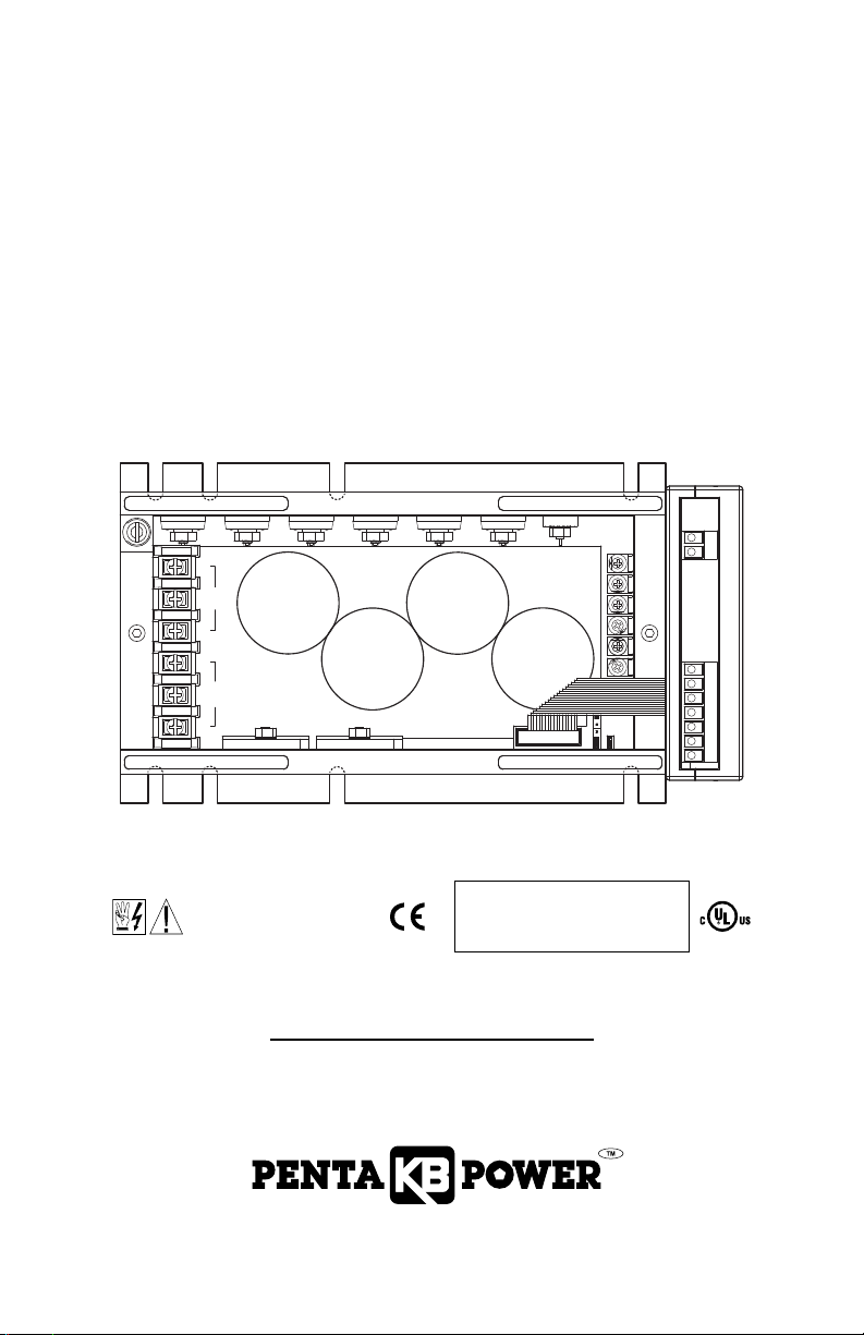
KBVF SERIES
Chassis/IP-20 AC Drives
Variable Speed/ Soft-Start AC Motor Drive
with Electronic Motor Overload Protection*
Rated for 208-230 and 400/460 Volt 50 & 60 Hz
3-Phase & PSC** AC Induction Motors from 2 thru 5 HP
Operates from 208/230 Volt and 400/460 Volt 50/60 Hz AC Line Input***
This Manual Covers Models KBVF-27, 29, 45, 48
See Safety Warning,
on page 8.
The information contained in this manual is intended to be accurate. However, the manufacturer retains
the right to make changes in design which may not be included herein.
*UL approved as an electronic overload protector for motors. **Custom software is required for PSC motors.
See PSC Motor Addendum (Part No. A42142). ***Do not use this drive with GFCIs. Special software is available –
contact our Sales Department. ****Installation of a CE approved RFI filter is required.
Note: The drive is factory set for
****
60 Hz motors. For 50 Hz motors,
see Section 6.1, on page 14.
© 2006 KB Electronics, Inc.
(see back cover)
Page 2

ection Page
S
1 Quick-Start Instructions . . . . . . . . . . . . . . . . . . . . . . . . . . . . . . . . . . . . . . . . . . . . . . . . . . . . . . . . . . . . . . . . 7
2 Safety Warning . . . . . . . . . . . . . . . . . . . . . . . . . . . . . . . . . . . . . . . . . . . . . . . . . . . . . . . . . . . . . . . . . . . . . . 8
Introduction . . . . . . . . . . . . . . . . . . . . . . . . . . . . . . . . . . . . . . . . . . . . . . . . . . . . . . . . . . . . . . . . . . . . . . . . . 9
3
Important Application Information . . . . . . . . . . . . . . . . . . . . . . . . . . . . . . . . . . . . . . . . . . . . . . . . . . . . . . . 13
4
5 Finger-Safe Cover . . . . . . . . . . . . . . . . . . . . . . . . . . . . . . . . . . . . . . . . . . . . . . . . . . . . . . . . . . . . . . . . . . . 14
6 Setting Selectable Jumpers . . . . . . . . . . . . . . . . . . . . . . . . . . . . . . . . . . . . . . . . . . . . . . . . . . . . . . . . . . . . 14
Mounting Instructions . . . . . . . . . . . . . . . . . . . . . . . . . . . . . . . . . . . . . . . . . . . . . . . . . . . . . . . . . . . . . . . . 15
7
8 Recommended High Voltage Dielectric Withstand Testing (Hi-Pot Testing) . . . . . . . . . . . . . . . . . . . . . . . . . 16
9 Wiring Instructions . . . . . . . . . . . . . . . . . . . . . . . . . . . . . . . . . . . . . . . . . . . . . . . . . . . . . . . . . . . . . . . . . . . 17
0 AC Line Fusing . . . . . . . . . . . . . . . . . . . . . . . . . . . . . . . . . . . . . . . . . . . . . . . . . . . . . . . . . . . . . . . . . . . . . 22
1
1 Drive Operation . . . . . . . . . . . . . . . . . . . . . . . . . . . . . . . . . . . . . . . . . . . . . . . . . . . . . . . . . . . . . . . . . . . . . 22
1
12 Diagnostic LEDs . . . . . . . . . . . . . . . . . . . . . . . . . . . . . . . . . . . . . . . . . . . . . . . . . . . . . . . . . . . . . . . . . . . . 22
13 Trimpot Adjustments . . . . . . . . . . . . . . . . . . . . . . . . . . . . . . . . . . . . . . . . . . . . . . . . . . . . . . . . . . . . . . . . . 23
Limited Warranty . . . . . . . . . . . . . . . . . . . . . . . . . . . . . . . . . . . . . . . . . . . . . . . . . . . . . . . . . . . . . . . . . . . . 28
Tables Page
1 General Performance Specifications . . . . . . . . . . . . . . . . . . . . . . . . . . . . . . . . . . . . . . . . . . . . . . . . . . . . . 11
2 Electrical Ratings . . . . . . . . . . . . . . . . . . . . . . . . . . . . . . . . . . . . . . . . . . . . . . . . . . . . . . . . . . . . . . . . . . . . 11
3 Terminal Block Wiring Information . . . . . . . . . . . . . . . . . . . . . . . . . . . . . . . . . . . . . . . . . . . . . . . . . . . . . . . 17
4 Drive Operating Condition and Run/Fault Relay Contact Status . . . . . . . . . . . . . . . . . . . . . . . . . . . . . . . . . 21
5 Fault Recovery and Resetting the Drive . . . . . . . . . . . . . . . . . . . . . . . . . . . . . . . . . . . . . . . . . . . . . . . . . . . 22
6 Drive Operating Condition and Status LED Indicator . . . . . . . . . . . . . . . . . . . . . . . . . . . . . . . . . . . . . . . . . 22
Figures Page
1 Models KBVF-27, 29 Quick-Start Connection Diagram . . . . . . . . . . . . . . . . . . . . . . . . . . . . . . . . . . . . . . . . 4
2 Models KBVF-45, 48 Quick-Start Connection Diagram . . . . . . . . . . . . . . . . . . . . . . . . . . . . . . . . . . . . . . . . 5
3 SIVFR Control Layout . . . . . . . . . . . . . . . . . . . . . . . . . . . . . . . . . . . . . . . . . . . . . . . . . . . . . . . . . . . . . . . . . 6
4 Mechanical Specifications and Control Layout . . . . . . . . . . . . . . . . . . . . . . . . . . . . . . . . . . . . . . . . . . . . . . 12
5 Expanded View of Jumpers and Trimpots . . . . . . . . . . . . . . . . . . . . . . . . . . . . . . . . . . . . . . . . . . . . . . . . . 13
6 Maximum Allowed Motor Torque vs. Speed . . . . . . . . . . . . . . . . . . . . . . . . . . . . . . . . . . . . . . . . . . . . . . . . 13
7 Open Ventilated Motor with External Cooling . . . . . . . . . . . . . . . . . . . . . . . . . . . . . . . . . . . . . . . . . . . . . . . 13
8 60 Hz and 50 Hz Motor Selection . . . . . . . . . . . . . . . . . . . . . . . . . . . . . . . . . . . . . . . . . . . . . . . . . . . . . . . 14
9 Available Torque vs. Output Frequency . . . . . . . . . . . . . . . . . . . . . . . . . . . . . . . . . . . . . . . . . . . . . . . . . . . 15
10 120 Hz and 100 Hz Drive Output Frequency Selection . . . . . . . . . . . . . . . . . . . . . . . . . . . . . . . . . . . . . . . 15
11 Automatic Start . . . . . . . . . . . . . . . . . . . . . . . . . . . . . . . . . . . . . . . . . . . . . . . . . . . . . . . . . . . . . . . . . . . . . 15
12 Models KBVF-27, 29 Forward/Reverse Speed Selection . . . . . . . . . . . . . . . . . . . . . . . . . . . . . . . . . . . . . . 15
13 Typical Hi-Pot Test Setup . . . . . . . . . . . . . . . . . . . . . . . . . . . . . . . . . . . . . . . . . . . . . . . . . . . . . . . . . . . . . . 16
14 AC Line Input, Motor, and Ground Connections . . . . . . . . . . . . . . . . . . . . . . . . . . . . . . . . . . . . . . . . . . . . 17
15 Models KBVF-27, 29 Main Speed Potentiometer Connection . . . . . . . . . . . . . . . . . . . . . . . . . . . . . . . . . . 18
16 Unidirectional Main Speed Potentiometer and Forward-Stop-Reverse Switch Connections . . . . . . . . . . . . 18
17 Bidirectional Main Speed Potentiometer Connection . . . . . . . . . . . . . . . . . . . . . . . . . . . . . . . . . . . . . . . . . 18
18 Models KBVF-27, 29 Voltage Following Signal Input Connection . . . . . . . . . . . . . . . . . . . . . . . . . . . . . . . . 19
19 Models KBVF-45, 48 Voltage Following Signal Input Connection . . . . . . . . . . . . . . . . . . . . . . . . . . . . . . . . 19
20 Models KBVF-45, 48 Current Following Signal Input Connection . . . . . . . . . . . . . . . . . . . . . . . . . . . . . . . . 19
21 Manual Start Switch Connection . . . . . . . . . . . . . . . . . . . . . . . . . . . . . . . . . . . . . . . . . . . . . . . . . . . . . . . . 19
22 Forward-Stop-Reverse Switch Connection . . . . . . . . . . . . . . . . . . . . . . . . . . . . . . . . . . . . . . . . . . . . . . . . 20
23 Form “C” Contact or Relay Forward-Stop-Reverse Connection . . . . . . . . . . . . . . . . . . . . . . . . . . . . . . . . . 20
24 Open Collector Forward-Stop-Reverse Connection . . . . . . . . . . . . . . . . . . . . . . . . . . . . . . . . . . . . . . . . . . 20
25 Enable Switch Connection . . . . . . . . . . . . . . . . . . . . . . . . . . . . . . . . . . . . . . . . . . . . . . . . . . . . . . . . . . . . . 21
26 Run/Fault Relay Connection . . . . . . . . . . . . . . . . . . . . . . . . . . . . . . . . . . . . . . . . . . . . . . . . . . . . . . . . . . . 21
27 Run/Fault Relay Output Contact Selection . . . . . . . . . . . . . . . . . . . . . . . . . . . . . . . . . . . . . . . . . . . . . . . . . 21
28 Models KBVF-27, 29 Minimum Speed Trimpot (MIN) Range . . . . . . . . . . . . . . . . . . . . . . . . . . . . . . . . . . . .23
TABLE OF CONTENTS
ii
Page 3

igures Page
F
29 SIVFR Offset Trimpot (OFFSET) . . . . . . . . . . . . . . . . . . . . . . . . . . . . . . . . . . . . . . . . . . . . . . . . . . . . . . . . . 23
30 Models KBVF-27, 29 Maximum Speed Trimpot (MAX) Range . . . . . . . . . . . . . . . . . . . . . . . . . . . . . . . . . . 23
1 Models KBVF-45, 48 Maximum Speed Trimpot (MAX) . . . . . . . . . . . . . . . . . . . . . . . . . . . . . . . . . . . . . . . . 24
3
2 Acceleration Trimpot (ACC) Range . . . . . . . . . . . . . . . . . . . . . . . . . . . . . . . . . . . . . . . . . . . . . . . . . . . . . . . 24
3
33 Deceleration Trimpot (DEC/B) Range . . . . . . . . . . . . . . . . . . . . . . . . . . . . . . . . . . . . . . . . . . . . . . . . . . . . . 24
34 Slip Compensation Trimpot (COMP) Range . . . . . . . . . . . . . . . . . . . . . . . . . . . . . . . . . . . . . . . . . . . . . . . . 24
5 Boost Trimpot (DEC/B) Range . . . . . . . . . . . . . . . . . . . . . . . . . . . . . . . . . . . . . . . . . . . . . . . . . . . . . . . . . . 25
3
36 Model KBVF-27 Current Limit Trimpot (CL) Range . . . . . . . . . . . . . . . . . . . . . . . . . . . . . . . . . . . . . . . . . . . 25
37 Model KBVF-29 Current Limit Trimpot (CL) Range . . . . . . . . . . . . . . . . . . . . . . . . . . . . . . . . . . . . . . . . . . . 25
8 Model KBVF-45 Current Limit Trimpot (CL) Range . . . . . . . . . . . . . . . . . . . . . . . . . . . . . . . . . . . . . . . . . . . 25
3
9 Model KBVF-48 Current Limit Trimpot (CL) Range . . . . . . . . . . . . . . . . . . . . . . . . . . . . . . . . . . . . . . . . . . . 26
3
Items Included in this Package:
KBVF Adjustable Frequency Drive, KBVF Series Installation and Operation Manual, Main Speed Potentiometer
Kit with Insulator and Mounting Hardware, 3 Main Speed Potentiometer Quick-Connect Terminals, 2-Wire and
3-Wire Connector Kit (Models KBVF-27, 29 Only), Status Indicator Label, Trimpot Adjustment Tool, CE
Approved Product Information Card, Warranty Registration Card.
TABLE OF CONTENTS (Continued)
UL Notice
230 VAC Controls
Suitable For Use On A Circuit Capable Of Delivering Not More Than 5 kA RMS Symmetrical Amperes,
230 Volts Maximum.
Use Copper Conductors Rated 75 ºC.
Suitable for Operation in a Maximum Surrounding Air Temperature of 40 ºC.
460 VAC Controls
Suitable For Use On A Circuit Capable Of Delivering Not More Than 5 kA RMS Symmetrical Amperes,
460 Volts Maximum.
Use Copper Conductors Rated 75 ºC.
Suitable for Operation in a Maximum Surrounding Air Temperature of 40 ºC.
iii
Page 4
CON1
CON2
C
ON3
X1 X2
J2
A/M
F - S - R
PWR
S
T
P3P2J1P1
50/60Hz
MAXCL ACCMIN DEC/B COMP
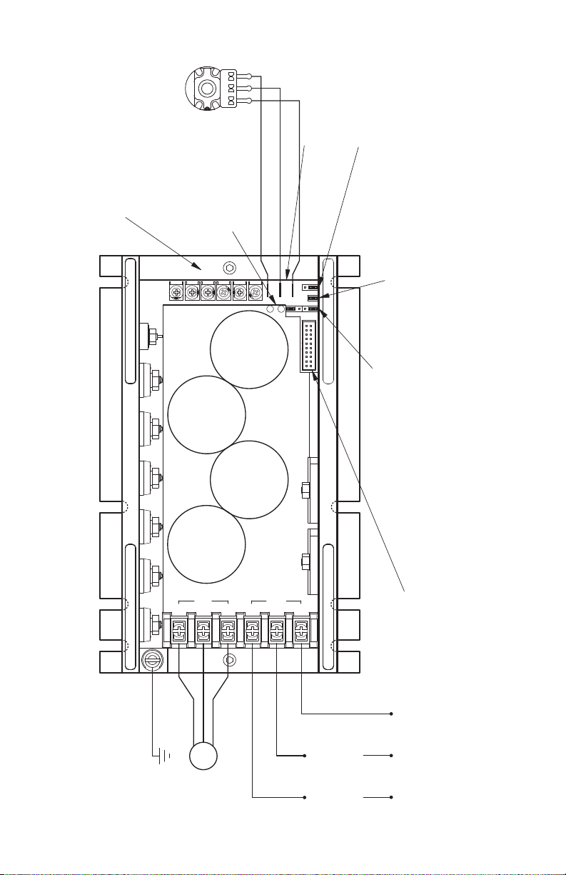
Main Speed Potentiometer (5 k)
see Section 9.4, on page 18.
(Supplied) (Front View):
Adjustable Trimpots:
see Section 13, on pages 23 – 26.
Motor Connection:
see Section 9.1, on page 17.
(Model KBVF-27 Only):
Single-Phase Connection
see Section 9.2, on page 17.
see Section 9.3, on page 18.
Ground (Earth):
Forward/Reverse Speed Selection:
see Section 9.7, on page 20.
see Section 9.8, on pages 20 and 21.
Enable Switch Connection,
Forward-Stop-Reverse Switch Connection:
see Section 6.3, on page 15.
for Accessories and Programming:
see Section 3.5, on page 10.
Communication Port
(Models KBVF-27, 29):
3-Phase Connection
see Section 9.1, on page 17.
(Use L1, L2, L3)
(Use L1, L2)
see Section 6.1.2, on page 15.
see Section 6.1.1, on page 14.
For 60 Hz or 50 Hz Motor Operation:
the Rated Motor RPM:
For Two Times
Automatic Start:
Manual Start Switch Connection:
see Section 9.6, on page 20.
see Section 6.2, on page 15.
Voltage Following Signal Input
see Section 9.5, on page 19.
in Lieu of Main Speed Potentiometer:
see Section 12, on pages 22 and 34.
Diagnostic LEDs:
High
Wiper
Low
Motor
L3
LINE
W
MOTOR
U
L2
AC
L1
VTB1
(Shown without Finger-Safe Cover Installed)
FIGURE 1 – MODELS KBVF-27, 29 QUICK-START CONNECTION DIAGRAM
4
Page 5
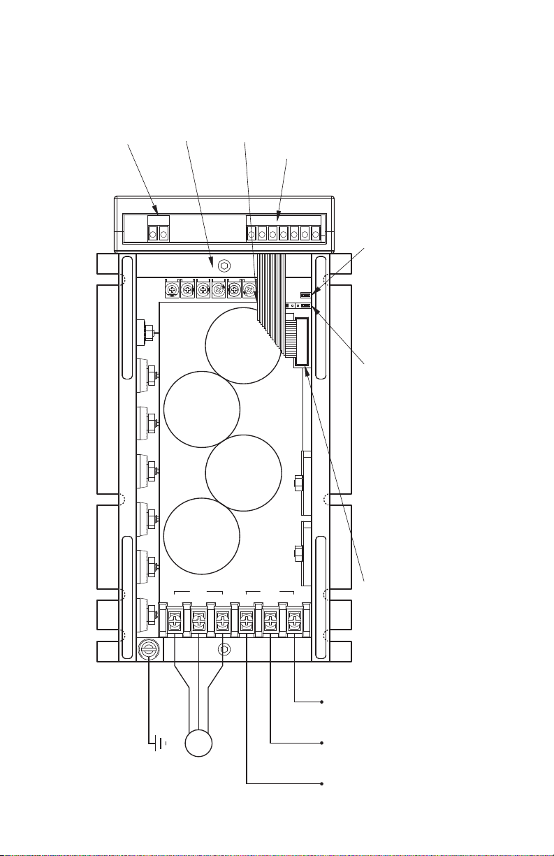
Ground (Earth):
Motor Connection:
see Section 9.2, on page 17.
see Section 9.3, on page 18.
3-Phase Connection:
AC Line
Motor
L3
W
L1
AC LINE
L2
VUTB1
MOTOR
5
0/60HzJ2
C
ON3
CON1
J1
X1 X2
A/M
CL MAX MIN ACC COMPDEC/B
TB1
TB2
see Section 9.1, on page 17.
(Isolated Inputs)
Main Speed Potentiometer (Supplied),
Run/Fault Relay Output Contacts:
(Located Under Ribbon Cable)
Signal Input, and Direction Switch
or Contact Connections:
see Section 12, on page 22.
see Section 13, on page 23.
Adjustable Trimpots:
Diagnostic LEDs
see Section 9.9, on page 21.
see Section 9.4 - 9.5 on Pages 18 and 19.
see Section 9.6, on page 20.
See Section 6.2, on page 15.
Manual Start Switch Connection:
Automatic Start:
see Section 6.1.2, on page 15.
For Two Times the Rated Motor RPM:
see Section 6.1.1, on page 14.
For 60 Hz or 50 Hz Motor Operation:Communication Port
see Section 3.5, on page 10.
for Accessories and Programming:
(Shown without Finger-Safe Cover Installed)
FIGURE 2 – MODELS KBVF-45, 48 QUICK-START CONNECTION DIAGRAM
5
Page 6
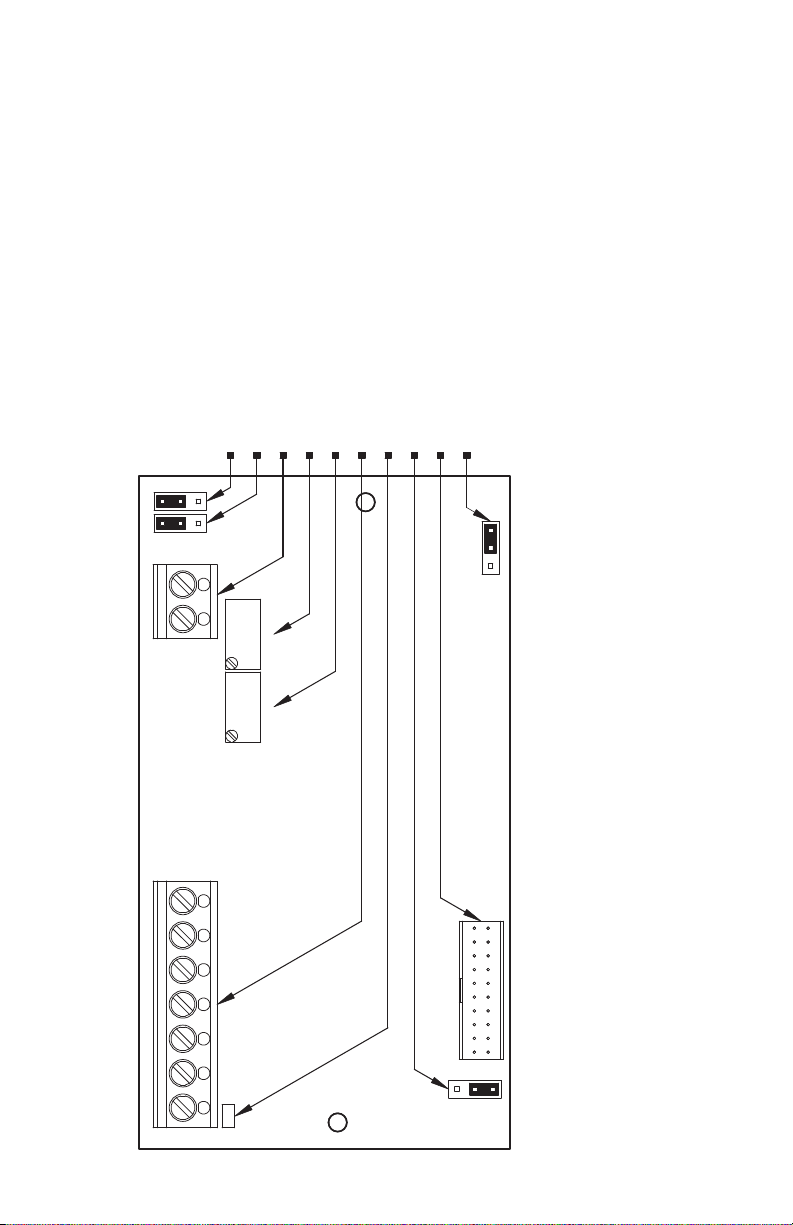
Signal Input, Direction Switch, and Main Speed Potentiometer connections.
Sets the drive for operation with a voltage or current input signal.
Sets the Run/Fault Relay Output Contacts for normally open or closed operation.
All jumpers are shown in factory set positions.
Run/Fault Relay Output Contacts connection.
Sets the operation of the Run/Fault Relay to Run or Fault.
Used to connect the Signal Isolator and Run/Fault Relay to the KBVF.
Sets the drive for operation with the optional Dynamic Brake Module.
MAXOFFSET
NDBM
J5
DBM
CON1
RUN
J4
FAULT
Power on LED.
Maximum Speed adjustment trimpot.
Signal Offset adjustment trimpot.
OV
PWR
TB1
-5V+5V FWD REV COM1SIG1
VOLTCUR
TB2
K1 K2
NC
J2J1
NO
FIGURE 3 – SIVFR CONTROL LAYOUT
(SIVFR is Built-In on Models KBVF-45, 48 and Optional on Models KBVF-27, 29)
6
Page 7

1 QUICK-START INSTRUCTIONS
mportant – You must read these simplified instructions before proceeding. These instructions are to be
I
sed as a reference only and are not intended to replace the details provided herein. You must read the
u
Safety Warning on, page 8, before proceeding.
See Figures 1 – 3, on pages 4 – 6. Also see Section 4 — Important Application Information, on
pages 13 and 14.
WARNING! Disconnect main power when making connections to the drive.
1.1 AC LINE CONNECTION – Wire the AC line input to Terminal Block TB1. Model KBVF-27 is designed
or single-phase (Terminals “L1”, “L2”) or 3-phase (Terminals “L1”, “L2”, “L3”) AC line input. Models
f
BVF-29, 45, 48 are designed for 3-phase (Terminals “L1”, “L2”, “L3”) AC line input only. See Figures
K
1 and 2, on pages 4 and 5. Also see Section 9.1, on page 17.
Application Note – Do not wire this drive to a GFCI. If operation with a GFCI is required,
contact our Sales Department.
Model KBVF-27 – Rated for 208/230 Volt single-phase or 3-phase AC line Input.
Model KBVF-29 – Rated for 208/230 Volt 3-phase AC line input.
Models KBVF-45, 48 – Rated for 400/460 Volt 3-phase AC line input.
1.2 GROUND CONNECTION – Connect the ground wire (earth) to the ground screw, as shown in
Figures 1 and 2, on pages 4 and 5. See Section 9.2, on page 17.
1.3 AC LINE FUSING – It is recommended that a fuse(s) or circuit breaker be installed in the AC line.
Fuse each conductor that is not at ground potential. For the recommended fuse size, see Table 2, on
page 11. Also see Section 10, on page 22.
1.4 MOTOR CONNECTION – Wire the motor to Terminals “U”, “V”, “W”, of Terminal Block TB1, as
shown in Figures 1 and 2, on pages 4 and 5. (Special reactors may be required for cable lengths over
100 ft. (30 m) – consult our Sales Department.) See Section 9.3, on page 18.
Note: The drive is programmed to operate 3-phase AC induction motors. For PSC motors, optional
software is required – consult our Sales Department.
1.5 MOUNTING INSTRUCTIONS – See Section 7, on page 15 and 16.
1.6 60 Hz & 50 Hz MOTOR OPERATION (JUMPERS J1 & J2 ON THE LOWER PC BOARD) – The
drive is factory set for 60 Hz motor operation (Jumper J1 set to the “60Hz” position and Jumper J2
set to the “X1” position). For 50 Hz motor operation, set Jumper J1 to the “50Hz” position and be
sure Jumper J2 is set to the “X1” position. See Section 6.1.1, on page 14.
1.7 TRIMPOT SETTINGS – All trimpots have been factory set for most applications, as shown in Figure
5, on page 13. Some applications require adjustments of the trimpots in order to tailor the drive for a
specific requirement. See Section 13, on pages 23 – 26.
1.8 MAIN SPEED POTENTIOMETER CONNECTION – The drive is supplied with a 5 kΩ potentiometer
(supplied) to control motor speed. On Models KBVF-27, 29, the potentiometer is to be connected to
terminals “P1”, “P2”, and “P3”. On Models KBVF-45, 48, the potentiometer is to be connected to the
SIVFR.
Models KBVF-27, 29
Unidirectional Speed Operation – Wire the potentiometer to Terminals “P1” (low), “P2” (wiper), “P3”
(high), as described in Section 9.4.1, on page 18. To select forward or reverse motor direction, see
Section 6.3, on page 15. To install a Forward-Stop-Reverse Switch, see Section 9.7.1, on page 20.
Bidirectional Speed Operation – See Section 9.4.2, on page 18.
7
Page 8

Models KBVF-45, 48
nidirectional Speed Operation – Wire the potentiometer to Terminals “+5V” (high), “SIG1” (wiper),
U
“COM1” (low), of Terminal Block TB1 on the SIVFR, as described in Section 9.4.2, on page 18. Be
sure Jumper J1, on the SIVFR, is set to the “VOLT” position (factory setting). A jumper must be
nstalled between Terminals “0V” and “FWD”, of Terminal Block TB1, in order for the drive to operate.
i
Bidirectional Speed Operation – Wire the potentiometer to Terminals “+5V” (high), “SIG1” (wiper),
– 5V” (low), of Terminal Block TB1 on the SIVFR, as described in Section 9.4.2, on page 18. Be sure
“
Jumper J1 (on the SIVFR) is set to the “VOLT” position (factory setting).
.9 SIGNAL FOLLOWING – An analog signal input can be used to control motor speed instead of the
1
Main Speed Potentiometer. The drive output will linearly follow the analog signal input. A Signal
Isolator (SIVFR) is built-in on Models KBVF-45,48 and optional on Models KBVF-27, 29.
Models KBVF-27, 29
Wire the isolated* 0 – 5 Volt DC signal input positive lead (+) to Terminal “P2” and the negative lead (–)
to Terminal “P1”. See Section 9.5, on page 19.
If a non-isolated signal is used, install the SIVFR Signal Isolator (Part No. 9597). The SIVFR accepts voltage (0 to ±2.5
*
hru 0 to ±25 Volts DC) or current (4 – 20 mA DC) signal inputs. See Section 3.5, on page 10.
t
Note: For signal following operation, the Minimum Speed Trimpot (MIN) must be set fully counterclockwise.
WARNING! The signal input must be isolated from the AC line. Earth grounding signal
wiring will damage the drive and void the warranty. It is highly recommended that the
SIVFR – Signal Isolator and Run/Fault Relay (Part No. 9597) be installed when using signal
following.
Models KBVF-45, 48
Wire the voltage (0 to ±2.5 thru 0 to ±25 Volt DC) or current (4 – 20 mA DC) signal input to Terminals
“SIG1” (+) and “COM1” (–) of Terminal Block TB1 on the SIVFR. For voltage following, be sure Jumper
J1 (on the SIVFR) is set to the “VOLT” position (factory setting). For current following, set Jumper J1
(on the SIVFR) to the “CUR” position. A jumper must be installed between Terminals “0V” and “FWD”,
of Terminal Block TB1, in order for the drive to operate.
2 SAFETY WARNING
Definition of Safety Warning Symbols
Electrical Hazard Warning Symbol – Failure to observe this warning could result in electrical
shock or electrocution.
Operational Hazard Warning Symbol – Failure to observe this warning could result in serious
injury or death.
This product should be installed and serviced by a qualified technician, electrician, or elec-
trical maintenance person familiar with its operation and the hazards involved. Proper instal-
lation, which includes installation of the Finger-Safe Cover, wiring, mounting in proper enclosure, fusing
or other current protection, and grounding can reduce the chance of electrical shocks, fires, or explo-
sion in this product or products used with this product, such as electric motors, switches, coils, sole-
noids, and/or relays. Eye protection must be worn and insulated adjustment tools must be used when
working with drive under power. This product is constructed of materials (plastics, metals, carbon, sili-
con, etc.) which may be a potential hazard. Proper shielding, grounding, and filtering of this product
can reduce the emission of radio frequency interference (RFI) which may adversely affect sensitive
electronic equipment. It is the responsibility of the equipment manufacturer and individual installer to
supply this Safety Warning to the ultimate end user of this product. (SW/FSC 5/2005) Be sure to follow
all instructions carefully. Fire and/or electrocution can result due to improper use of this product.
8
Page 9

This product complies with all CE directives pertinent at the time of manufacture. Contact our Sales
epartment for Declaration of Conformity. Installation of a CE approved RFI filter is required. See RFI
D
ilters & Chokes Selection Guide D-321 (Part No. A42027) for selection of filters to meet the Industrial or
F
Residential Standard. Additional shielded cable and/or AC line cables may be required along with a signal
isolator (SIVFR (Part No. 9597)).
INTRODUCTION
3
Thank you for purchasing the KBVF Adjustable Frequency Drive. KB Electronics, Inc. is committed to providing total customer satisfaction by producing quality products that are easy to install and operate. The
BVF is manufactured with surface mount components incorporating advanced circuitry and technology. A
K
inger-Safe Cover is included for added liability protection.
F
he KBVF Adjustable Frequency Drives provide variable speed control for standard 3-phase and Permanent
T
Split Capacitor (PSC)
1
AC induction motors from 2 thru 5 HP. This manual covers models with single-phase
and 3-phase AC line input. The sine wave coded Pulse Width Modulated (PWM) output operates at a carrier
frequency of 16 kHz, which provides high motor efficiency and low noise. Adjustable linear acceleration and
deceleration are provided, making the drive suitable for soft-start applications.
Due to its user-friendly design, the KBVF AC drive is easy to install and operate. Tailoring to specific applications is accomplished with selectable jumpers and trimpots, which eliminate the computer-like programming
required on other drives. However, for most applications no adjustments are necessary. For more advanced
programming, PC based Drive-Link™ software is available.
Main features include adjustable RMS Current Limit and I
2
t Motor Overload Protection.2In addition,
Adjustable Slip Compensation with Static Auto-Tune and Boost provides high torque and excellent load regulation over a wide speed range. Power Start™ delivers over 200% motor torque to ensure startup of high
frictional loads. Electronic Inrush Current Limit (EICL™) eliminates harmful AC line inrush current. The drive is
suitable for machine or variable torque (HVAC) applications. With optional Drive-Link™ software, the drive
can be programmed for DC Injection Braking.
For AC line and motor wiring, a barrier terminal block is provided. Other features include: adjustable trimpots
(MIN, MAX, ACC, DEC/B
3
, COMP, CL), customer selectable jumpers (Automatic-Manual Start, Motor
Frequency, Frequency Multiplier, Forward/Reverse). Diagnostic LEDs are provided for power (PWR) and
drive status (ST). A 5 kΩ Main Speed Potentiometer is also included.
A Signal Isolator (built-in on Models KBVF-45,48 and optional on Models KBVF-27, 29) can be used for
unidirectional or bidirectional speed control and accepts voltage and current signal input. Other optional
accessories include: Multi-Speed Board, Programming Kit, and Modbus Communication Module. A connector is provided for easy installation of accessories.
Notes: 1. Optional software is required for PSC motors – contact our Sales Department. 2. UL approved as
an electronic overload protector for motors. 3. In 50 Hz Mode, the DEC/B Trimpot automatically becomes
Adjustable Boost.
3.1 STANDARD FEATURES
• Simple to Operate – Does not require programming. Uses trimpots and jumpers, which are factory
set for most applications.
• Diagnostic LEDs – Power on (PWR) and drive status (ST). See Section 12, on page 22 and 23.
• Jumper Selection of Drive Output Frequency – Increases the motor speed up to two times the
rated RPM. See Section 6, on page 14 and 15.
• Industry Standard Mounting – See Section 7, on page 15 and 16.
• Finger-Safe Cover – Meets IP-20 standard. See Section 5, on page 14.
• Models KBVF-29, 48 contain a built-in cooling fan.
Note: GFCI Operation – This drive can operate with GFCIs (optional software required) – contact our
Sales Department.
9
Page 10

3.2 PERFORMANCE FEATURES
Power Start™ – Provides more than 200% starting torque which ensures startup of high
•
frictional loads.
Slip Compensation with Static Auto-Tune and Boost – Provides excellent load regulation over a
•
wide speed range.
Speed Range – 60:1
•
3.3 PROTECTION FEATURES
2
Motor Overload (I
•
) with RMS Current Limit – Provides motor overload protection which prevents
t
motor burnout and eliminates nuisance trips. UL approved as an electronic overload protector for
motors. See Section 4.2, on pages 13 and 14. Also see Section 13.7, on pages 25 and 26.
Electronic Inrush Current Limit (EICL™) – Eliminates harmful inrush AC line current during startup.
•
• Short Circuit – Prevents drive failure if a short circuit occurs at the motor (phase-to-phase).
• Regeneration – Eliminates nuisance tripping due to high bus overvoltage caused by rapid decelera-
tion of high inertial loads.
• Undervoltage and Overvoltage – Shuts down the drive if the AC line input voltage goes above or
below the operating range.
• MOV Input Transient Suppression.
• Microcontroller Self Monitoring and Auto-Reboot.
3.4 TRIMPOT ADJUSTMENTS
• Minimum Speed (MIN on Models KBVF-27, 29 and OFFSET on SIVFR of Models KBVF-45, 48)
Sets the minimum speed of the motor. See Section 13.1, on page 23.
• Maximum Speed (MAX) – Sets the maximum speed of the motor. See Section 13.2, on page 23.
• Acceleration (ACC) – Sets the amount of time for the motor to accelerate from zero speed to full
speed. See Section 13.3, on page 24.
• Deceleration (DEC/B) – Sets the amount of time for the motor to decelerate from full speed to zero
speed. See Section 13.4, on page 24.
• Slip Compensation (COMP) – Maintains set motor speed under varying loads. See Section 13.5,
on page 24.
• Boost (DEC/B) – In 50 Hz mode, the trimpot automatically becomes Adjustable Boost, which can
be used to set the Volts/Hz Curve for 50 Hz motors to obtain maximum performance. In 50 Hz
Mode, the deceleration time is automatically set to the same as the acceleration time. See Section
13.6, on page 25.
• Current Limit (CL) – Sets the current limit (overload) which limits the maximum current (torque) to
the motor. See Section 13.7, on pages 25 and 26.
3.5 OPTIONAL ACCESSORIES
• SIVFR – Signal Isolator and Run/Fault Relay (Part No. 9597) – Provides isolation between a
non-isolated signal voltage (0 to ±2.5 thru 0 to ±25 Volts DC) or current source (4 – 20 mA DC) and
the drive. Can be used in unidirectional or in bidirectional mode. Run/Fault Relay Output Contacts
are also provided, which can be used to turn on or off equipment or to signal a warning if the drive
is put into the Stop Mode or a fault has occurred. Mounts on the end of the drive. This option is
built-in on models KBVF-45, 48.
• Multi-Speed Board (Part No. 9503) – Provides multi-speed operation using external contacts or a
PLC. Mounts on the end of the drive. For Models KBVF-27, 29 only. Also available factory installed
on Models KBVF-45, 48 – contact our Sales Department.
• Programming Kit (Part No. 9582) – Includes DownLoad Module™ (DLM) handheld programming
device which uploads and downloads drive programs, PC to DLM serial communication cable, DLM
10
to inverter communication cable, and PC Windows® based Drive-Link™ communication software.
Page 11

• DIVF – Modbus Communication Module (Part No. 9568) – Allows the drive to communicate with
LCs, PCs, and HMIs with Modbus RTU protocol utilizing a serial communication cable. If a USB
P
communication cable is required, purchase Part No. 19008.
• Custom Software – All models can be factory programmed for applications which require special
switching, timing, PLC functions, and GFCI operation – contact our Sales Department.
ABLE 1 – GENERAL PERFORMANCE SPECIFICATIONS
T
Factory
Description Specification
208/230 Volt AC Line Input Voltage Operating Range (Volts AC) 208 (–15%) / 230 (+15%) —
400/460 Volt AC Line Input Voltage Operating Range (Volts AC) 380 (–15%) – 460 (+15%) —
M
aximum Load (% Current Overload for 2 Minutes)
1
50
Carrier, Switching Frequency (kHz) 16, 8 —
Signal Following Input Voltage Range1(Volts DC)
Signal Following Input Current Range1(mA DC)
KBVF-27, 29 0 – 5 —
KBVF-45, 48 0 to ±2.5 thru 0 to ±25 0 to ±5
4 – 20 —
Output Frequency Resolution (Bits, Hz) 10, .06 —
M
inimum Speed Trimpot (MIN) Range (% Frequency Setting)
0
– 40
Maximum Speed Trimpot (MAX) Range (% Frequency Setting) 70 – 110 100
Acceleration Trimpot (ACC) and Deceleration Trimpot (DEC/B) Range (Seconds) .3 – 20 1.5
Boost Trimpot (DEC/B) Range (50 Hz Only) (Volts/Hz) 0 – 30 5
Slip Compensation Trimpot (COMP) Range at Drive Rating (Volts/Hz) 0 – 3 1.5
KBVF-27 4.0 – 12.5 10.7
Current Limit Trimpot (CL) Range (Amps AC)
KBVF-29 5.5 – 17.0 14.4
KBVF-45 3.0 – 8.5 7.4
KBVF-48 5.0 – 15.5 13.3
Motor Frequency Setting (Hz) (Jumper J1) 50, 60 60
Output Frequency Multiplier (X1, X2) (Jumper J2)
2
1, 2 1
Minimum Operating Frequency at Motor (Hz) 1 —
Speed Range (Ratio) 60:1 —
Speed Regulation (30:1 Speed Range, 0 – Full Load) (% Base Speed)
Overload Protector Trip Time for Stalled Motor (Seconds) 6 —
AC Line Input Undervoltage/Overvoltage Trip Points for 208/230 Volt AC Line (±5%) (Volts AC)
AC Line Input Undervoltage/Overvoltage Trip Points for 400/460 Volt AC Line (±5%) (Volts AC)
Run/Fault Relay Output Contacts Rating5(Amps at 30 Volts DC, 125 Volts AC, 250 Volts DC)
3
4
4
2.5 —
151 – 282 —
302 – 567 —
1, 0.5, 0.25 —
Operating Temperature Range (°C / °F) 0 – 45 / 32 – 113 —
Notes: 1. Models KBVF-27, 29: if a non-isolated signal is used, or if using 0 to ±2.5 thru 0 to ±25 Volts DC or 4 – 20 mA DC signal input, install the
SIVFR Signal Isolator (Part No. 9597). Models KBVF-45, 48: contain built-in signal isolation. 2. Allows the motor to operate up to two times the rated
RPM. Constant motor horsepower will result when operating the drive in the “X2” mode above the motor rated frequency. 3. Dependent on motor performance. 4. Do not operate the drive outside the specified AC line input voltage operating range. 5. Models KBVF-45, 48 only.
Setting
—
0
TABLE 2 – ELECTRICAL RATINGS
AC Line Input Drive Output
Part
Model
Volts AC
No.
(50/60 Hz)
KBVF-27 9591 208/230
1
KBVF-29
KBVF-45
KBVF-48
9593 208/230 3 10.8 0 – 230 9.0 3 (2.25) 15 4.6 2.1
2
9590 400/460 3 5.3 0 – 400/460 4.6 3 (2.25) 10 4.1 1.9
1, 2
9592 400/460 3 9.6 0 – 400/460 8.3 5 (3.75) 15 4.6 2.1
Maximum
Phase
Current
(φ)
(Amps AC)
1 17.0
3 8.0 10
Voltage
Range
(Nominal)
(Volts AC)
0 – 230 6.7 2 (1.5)
Maximum
Continuous
Load Current
(RMS Amps/Phase)
Maximum
Horsepower
(HP (kW)) lbs kg
Notes: 1. Models KBVF-29, 48 contain built-in cooling fan. 2. Models KBVF-45, 48 are rated 0 – 400 Volts AC for 50 Hz motor operation and 0 – 460
Volts AC for 60 Hz motor operation.
*All models contain a Terminal Block for AC line and motor wiring. The Signal Isolator and Run/Fault Relay is standard on Models KBVF-45, 48
and optional on Models KBVF-27, 29.
Fuse or
Circuit
Breaker
Rating
(Amps)
20
Net Wt.
4.1 1.9
11
Page 12

built-in cooling fan on this end
31.8
12.7
0.5
(8 Places)
5.1
0.2
(Models KBVF-45, 48)
217
Models KBVF-29, 48 contain a
76.2
1.25
3.00
178
(Models KBVF-27, 29)
191
7.00
7.50
8.55
(optional on models KBVF-27, 29)
is standard on models KBVF-45, 48
Signal Isolator and Run/Fault Relay
4.00
102
119
99.0
3.90
4.70
built-in cooling fan
Models KBVF-29, 48 contain a
113113
KBVF-27: KBVF-29:
110110
KBVF-45: KBVF-48:
4.35 4.35
Maximum Height
4.45 4.45
4.15
105
See
Chart
L3
W
L1
AC LINE
L2
VUTB1
MOTOR
50/60HzJ2
C
ON3
CON1
J1
X1 X2
A/M
CL MAX MIN ACC COMPDEC/B
TB1
TB2
(SEE FIGURE 5, ON PAGE 13, FOR EXPANDED VIEW OF JUMPERS AND TRIMPOTS)
FIGURE 4 – MECHANICAL SPECIFICATIONS (INCHES/mm) & CONTROL LAYOUT
12
(TOP VIEW SHOWN WITHOUT FINGER-SAFE COVER INSTALLED) (SIDE VIEW SHOWN WITH FINGER-SAFE COVER INSTALLED)
Page 13

4 IMPORTANT APPLICATION INFORMATION
60
Motor Speed (%)
TEFC and Open Ventilated
50304010020
Motors
Maximum Allowed
Motor Torque (%)
40
20
60
0
and TENV
I
nverter Duty
100
80
100907080
Motors
Fan Cooled
Selectable Jumpers
A/M
CON2
CON1
J2 50/60Hz
CON3
J1X2X1
P1
F - S - R
PWR
P3P2
ST
Diagnostic LEDs
Main Speed Potentiometer
and Signal Input Terminals
MINCL MAX ACCDEC/B COMP
Adjustable Trimpots
Open Ventilated Motor
(100 CFM Min.)
Fan or Blower
Airflow
.1 MOTOR WITH EXTERNAL FAN
4
COOLING – Most totally enclosed fan-
cooled (TEFC) and open ventilated 3-
hase AC induction motors will over-
p
eat if used beyond a limited speed
h
range at full torque. Therefore, it is necessary to reduce motor load as speed
s decreased.
i
ote: Some fan-cooled motors can be
N
used over a wider speed range.
Consult the motor manufacturer for
etails.
d
WARNING! Some motors have
low speed characteristics which
cause overheating and winding failure
under light load or no load conditions.
If the motor is operated in this manner
for an extended period of time, it is
recommended that the unloaded motor
current be checked from 2 – 15 Hz (60
– 450 RPM) to ensure motor current
does not exceed the nameplate rating.
Do not use motor if the motor current exceeds the nameplate rating.
FIGURE 5 – EXPANDED VIEW OF JUMPERS AND TRIMPOTS
It is recommended that
FIGURE 6 – MAXIMUM ALLOWED MOTOR TORQUE vs. SPEED
the drive be used with
Inverter Duty or TENV motors.
Inverter duty and most totally
enclosed non-ventilated (TENV)
motors can provide full rated
torque over an extended speed
range without overheating. See
Figure 6.
If external fan cooling is provided,
open ventilated motors can also
achieve an extended speed range
at full rated torque. A box fan or
FIGURE 7 – OPEN VENTILATED MOTOR WITH EXTERNAL COOLING
blower with a minimum of 100
CFM per HP is recommended.
Mount the fan or blower so the
motor is surrounded by the airflow. See Figure 7.
4.2 ELECTRONIC MOTOR
OVERLOAD PROTECTION –
The drive contains Modified I
Overload Protection.* Part of this
function consists of a Current
Limit (CL) circuit, which limits the
drive current to a factory preset
2
t
13
Page 14

level of 160% of the rated drive current. The CL Trimpot is used to recalibrate the drive current from
J2
J1
50/60Hz
X1 X2J2J1
50/60Hz
X1 X2
0% thru 200%. The Power Start™ circuit provides an overshoot function that allows most motors to
6
develop more than 200% of starting torque and breakdown torque.
Standard I
2
t is undesirable because it causes nuisance tripping. It allows a very high motor current to
develop and will turn the drive off after a short period of time. KB’s RMS Current Limit Circuit avoids
his nuisance tripping while providing maximum motor protection.
t
If the motor is overloaded to 120% of full load (75% of the CL setting), the I
otor continues to be overloaded at the 120% level, the timer will shut down the drive after 30 min-
m
2
t Timer starts. If the
utes. If the motor is overloaded to 160% of full load, the drive will trip in 6 seconds.
UL approved as an overload protector for motors.
*
5 FINGER-SAFE COVER
The drive is designed with an IP-20 Finger-Safe Cover which provides protection against accidental contact
with high voltage.
WARNING! Disconnect main power when removing or installing the Finger-Safe Cover.
WARNING! To prevent accidental contact with high voltage, it is required that the Finger-Safe
Cover be properly installed onto the drive after all wiring and setup is complete. It offers
protection against electric shock which limits the potential liability to the equipment manufacturer
and installer.
5.1 REMOVING THE FINGER-SAFE COVER – The Finger-Safe Cover will have to be removed before
wiring the drive or setting selectable jumpers. All trimpots can be readjusted with the Finger-Safe
Cover installed. Notice the orientation of the Finger-Safe Cover before removing it.
To remove the Finger-Safe Cover, gently lift up on the four retainer clips until the cover disengages
from the base.
Note: The Finger-Safe Cover is designed with a removable panel (on the trimpots side) which must be
removed for installation of optional accessories SIVFR Signal Isolator and Run/Fault Relay (Part No.
9597) or Multi-Speed Board (Part No. 9503). Complete instructions are provided with the accessories.
5.2 INSTALLING THE FINGER-SAFE COVER – To install the Finger-Safe Cover, be sure to properly align
the retainer clips. Gently push the Finger-Safe Cover onto the base until the retainer clips are fully
engaged with the base.
6 SETTING SELECTABLE JUMPERS
The drive has customer selectable jumpers
which must be set before the drive can be
used. For the location of jumpers, see Figure 5,
on page 13.
6.1 60H
Z AND 50 HZ MOTOR OPERATION
AND DRIVE OUTPUT FREQUENCY
SELECTION (JUMPERS J1 AND J2) –
Both jumpers must be set for the appropriate motor nameplate frequency rating. Jumpers J1 and J2 are located on the lower PC board.
6.1.1 Setting the Drive for 60 Hz or 50 Hz Motor Operation – The drive is factory set to operate
60 Hz motors. Jumper J1 is factory set to the “60Hz” position and Jumper J2 is factory set to
the “X1” position. For 50 Hz motors, set Jumper J1 to the “50Hz” position and be sure Jumper
J2 is set to the “X1” position. See Figure 8.
14
FIGURE 8 – 60 Hz & 50 Hz MOTOR SELECTION
60 Hz Motor Operation
(Factory Setting)
(J1 Installed in “60Hz” Position)
(J2 Installed in “X1” Position)
50 Hz Motor Operation
(J1 Installed in “50Hz” Position)
(J2 Installed in “X1” Position)
Page 15

6.1.2 Setting the Drive for Two
50/60
Output Frequency (Hz)
% Torque
0
02
50
100
100/120
J2J150/60Hz
X1 X2J2J1
50/60Hz
X1 X2
A/M
CON1
F - S - R
CON2
F - S - R
CON2
imes the Rated Motor RPM –
T
The drive can also be used to
operate the motor up to two
imes the rated RPM. However,
t
onstant horsepower will result
c
when operating the drive in the
“X2” mode above the motor
ated frequency. See Figure 9.
r
or 120 Hz output with 60 Hz
F
motor, be sure Jumper J1 is set
to the “60Hz” position and set
umper J2 to the “X2” position.
J
For 100 Hz output with 50 Hz
motor, set Jumper J1 to the
“50Hz” position and set Jumper
J2 to the “X2” position. See
Figure 10.
FIGURE 9 – AVAILABLE TORQUE vs. OUTPUT FREQUENCY
6.2 AUTOMATIC START (CON1) – The
drive is factory set for Automatic Start
(jumper installed onto CON1), as shown
in Figure 11. CON1 is located on the
lower PC board. The drive will automati-
120 Hz Output with 60 Hz Motor
(J1 Installed in “60Hz” Position)
(J2 Installed in “X2” Position)
FIGURE 10 – 120 Hz & 100 Hz
DRIVE OUTPUT FREQUENCY SELECTION
100 Hz Output with 50 Hz Motor
(J1 Installed in “50Hz” Position)
(J2 Installed in “X2” Position)
cally start when power is applied and a
run command is given. The drive will
automatically restart after a recovered
fault due to undervoltage, overvoltage,
or short circuit.
2
For an I
t Trip, due to a prolonged overload, the drive must be
manually restarted. See Section 11.2, on page 22. Also see
FIGURE 11 – AUTOMATIC START
(Jumper Installed)
Section 12.2, on page 23.
For Manual Start, a momentary contact must be installed onto
CON1, as described in Section 9.6, on page 20.
6.3 FORWARD/REVERSE SPEED
SELECTION – Models KBVF-27, 29 are
factory set for Forward Speed Operation
(jumper installed in the “F-S” position of
CON2). For reverse Speed Operation, install
(Jumper Installed in “F” Position)
FIGURE 12 – MODELS KBVF-27, 29
FORWARD/REVERSE SPEED SELECTION
Forward Speed Operation
(Factory Setting)
Reverse Speed Operation
(Jumper Installed in “R” Position)
the jumper in the “R-S” position. CON2 is
located on the lower PC board. See Figure
12. See Section 9.7, on page 20.
To wire a Forward-Stop-Reverse Switch,
or if installing the SIVFR Signal Isolator (built-in on Models KBVF-45, 48), see Section 9.7, on page 20.
7 MOUNTING INSTRUCTIONS
ture, metal chips, dust, and other contamination, including corrosive atmosphere that may be harm-
WARNING! This drive must be mounted in an enclosure. Care should be taken to avoid
extreme hazardous locations where physical damage to the drive can occur due to mois-
ful. See Safety Warning on pages 8 and 9. To prevent accidental contact with high voltage, it is
required that the Finger-Safe Cover be properly installed onto the drive after all wiring and setup is
complete. Do not use this drive in an explosion proof application.
15
Page 16
The enclosure should be large enough to allow for proper heat dissipation so that the ambient temperature
12
30
AC KILOVOLTS
10mA
LEAKAGE
0mA
High Voltage Dielectric Withstand Tester (Hi-Pot Tester)
ZERO
MAX
VOLTAGETEST
RESETH. V.
RETURN
(Main Power Disconnected)
to AC Line Inputs
Connect Hi-Pot
AC Line Input
L1
L2
Chassis
Auxiliary Equipment
Chassis
Frame
Motor Wires
(Main Power Disconnected)
Connect All Drive Terminals Together
P3
Signal Inputs
P1
P2
W
L1
L2
U
V
L3
Adjustable Frequency Drive
Machine Equipment or Frame
oes not exceed 45 °C (113 °F). Leave enough room to allow for AC line, motor connection, and other
d
wiring that is required. See Figure 4, on page 12.
When mounting the Main Speed Potentiometer, be sure to install the insulating disc between the potentiometer and the panel.
odels KBVF-29, 48:
M
1. When mounting these drives in a vertical direction, the cooling fan must be on top.
2. When mounting the drive in an enclosure, be sure to leave at least 2” of clearance around the cooling
fan for proper heat dissipation.
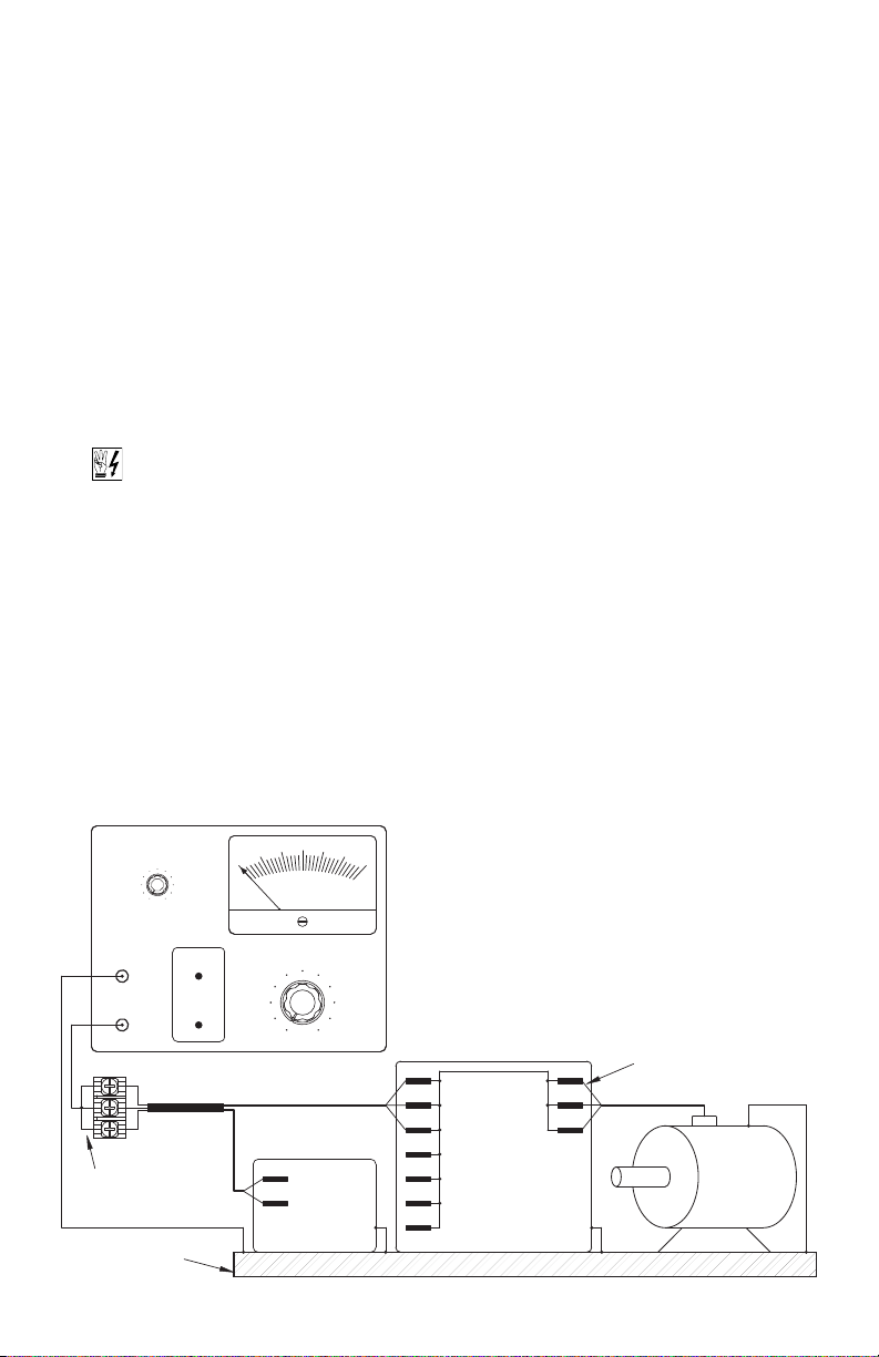
8 RECOMMENDED HIGH VOLTAGE DIELECTRIC WITHSTAND TESTING (HI-POT TESTING)
esting agencies such as UL, CSA, etc., usually require that equipment undergo a hi-pot test. In order to
T
prevent catastrophic damage to the drive, which has been installed in the equipment, the following procedure is recommended. A typical hi-pot test setup is shown in Figure 13. All drives have been factory
hi-pot tested in accordance with UL requirements.
Warning! All equipment AC line inputs must be disconnected from the AC power.
8.1 Connect all equipment AC power input lines together and connect them to the H.V. lead of the Hi-Pot
Tester. Connect the RETURN of the Hi-Pot Tester to the frame on which the drive and other auxiliary
equipment are mounted.
8.2 The Hi-Pot Tester must have an automatic ramp-up to the test voltage and an automatic ramp-down
to zero voltage.
Note: If the Hi-Pot Tester does not have automatic ramping, then the hi-pot output must be manually
increased to the test voltage and then manually reduced to zero. This procedure must be followed for
each machine being tested. A suggested Hi-Pot Tester is Slaughter Model 2550.
16
CAUTION! Instantly applying the hi-pot voltage will cause irreversible damage to the drive, which will
void the warranty.
FIGURE 13 – TYPICAL HI-POT TEST SETUP
Page 17

9 WIRING INSTRUCTIONS
Ground (Earth):
see Section 9.2.
(Model KBVF-27 Only):
Single-Phase Connection
(Use L1, L2)
see Section 9.1.
see Section 9.3, on Page 18.
Motor Connection:
(Use L1, L2, L3)
see Section 9.1.
(Models KBVF-27, 29, 45, 48):
3-Phase Connection
L3
Motor
MOTOR AC LINE
L2L1
WTB1 VU
WARNING! Read Safety Warning, on pages 8 and 9, before using the drive. Disconnect
main power when making connections to the drive. To avoid electric shock, be sure to
roperly ground the drive.
p
pplication Note – To avoid erratic operation, do not bundle the AC line and motor wires with each other
A
or with wires from signal following, start/stop contacts, or any other signal wires. Also, do not bundle motor
wires from multiple drives in the same conduit. Use shielded cables on all signal wiring over 12” (30 cm).
he shield should be earth grounded on the drive side only. Wire the drive in accordance with the National
T
Electrical Code requirements and other local codes that may apply.
Be sure to properly fuse each AC line conductor that is not at ground potential. Do not fuse neutral or
grounded conductors. A separate AC line switch or contactor must be wired as a disconnect so that each
ngrounded conductor is opened. For fuse or circuit breaker selection, see Section 10, on page 22.
u
TABLE 3 – TERMINAL BLOCK WIRING INFORMATION*
Terminal Block Maximum Wire Size (Cu) Recommended Tightening Torque
Designation Description Location AWG
TB1 AC Line Input and Motor Wiring Upper PC Board 12 3.3 12 14
TB1**
TB2** Run/Fault Relay Output Contacts SIVFR*** 16 1.3 3.5 4
*Models KBVF-27, 29 contain quick-connect terminals for signal input. Connectors are provided for wiring of Direction Switch and Manual Start Switch.
**Models KBVF-45, 48 only. ***SIVFR – Signal Isolator and Run/Fault Relay is standard on Models KBVF-45, 48 and optional on Models KBVF-27, 29.
Signal Input, Direction Switch,
and Main Speed Potentiometer
SIVFR*** 16 1.3 3.5 4
mm
2
in-lbs kg-cm
9.1 AC LINE CONNECTION – Wire the
AC line input to Terminal Block TB1.
Model KBVF-27 is designed for
single-phase (Terminals “L1”, “L2”) or
3-phase (Terminals “L1”, “L2”, “L3”)
AC line input. Models KBVF-29, 45,
48 are designed for 3-phase
(Terminals “L1”, “L2”, “L3”) AC line
input only. See Figures 1 and 2, on
pages 4 and 5.
Application Note: GFCI Operation –
Do not connect this drive to an AC
power source controlled by a
Ground Fault Circuit Interrupter.
Special software is required for
GFCI operation – contact our Sales
Department.
Model KBVF-27 – Rated for 208/230
Volt single-phase or 3-phase AC line
Input.
Model KBVF-29 – Rated for 208/230
Volt 3-phase AC line input.
Models KBVF-45, 48 – Rated for
400/460 Volt 3-phase AC line input.
9.2 GROUND CONNECTION – Connect the ground wire (earth) to the green ground screw. The ground
screw is located on the heat sink. See Figure 14.
FIGURE 14 – AC LINE INPUT, MOTOR, AND GROUND CONNECTIONS
17
Page 18

9.3 MOTOR CONNECTION – Wire the motor to
Wiper
Low
High
P1
(Supplied) (Front View)
Main Speed Potentiometer
P3P2
REV
High
Stop
-5V
TB1
+5V 0V FWD
Forward
Wiper
Potentiometer
Main Speed
(5 k)
Low
Reverse
SIG1 COM1
SIVF
TERMINAL
BLOCK
CUR VOLT
J1
REV-5V
TB1
+5V 0V FWD SIG1 COM1
Main Speed
Potentiometer
Wiper
(5 k)
High
Jumper
Low
Jumper
CUR VOLT
J1
SIVF
TERMINAL
BLOCK
erminals “U”, “V”, “W”. The terminals are located
T
on the upper PC board. See Figure 14, on page
17. Motor cable length should not exceed 100 ft
30 m) – special reactors may be required – con-
(
ult our Sales Department.
s
Note: The drive is programmed to operate
3-phase AC induction motors. For PSC motors,
ptional software is required – contact our Sales
o
epartment.
D
.4 MAIN SPEED POTENTIOMETER CONNECTION
9
The drive is supplied with a 5 kΩ Main Speed
–
Potentiometer to control motor speed.
WARNING! Do not earth
Potentiometer terminals.
ground any Main Speed
FIGURE 16 – UNIDIRECTIONAL MAIN SPEED POTENTIOMETER &
Note: When mounting the Main
Speed Potentiometer, be sure to
install the insulating disc (supplied)
between the potentiometer and the
panel.
9.4.1 Models KBVF-27, 29 – Wire
the Main Speed
Potentiometer to Terminals
“P1” (low), “P2” (wiper), “P3”
(high). The terminals are located on the lower PC board.
See Figure 15.
If installing the SIVFR Signal
Isolator, see Section 9.4.2.
9.4.2 Models KBVF-45, 48 – Wire
the Main Speed
Potentiometer to Terminal
Block TB1 on the SIVFR.
FIGURE 15 – MODELS KBVF-27, 29
MAIN SPEED POTENTIOMETER CONNECTION
UNIDIRECTIONAL OPERATION)
(
FORWARD-STOP-REVERSE SWITCH CONNECTIONS
(JUMPER J1 INSTALLED IN “VOLT” POSITION)
FIGURE 17 – BIDIRECTIONAL
MAIN SPEED POTENTIOMETER CONNECTION
(TERMINALS “FWD”, “REV”, “COM1” HARDWIRED)
(JUMPER J1 INSTALLED IN “VOLT” POSITION)
18
For Unidirectional Speed
Operation: Wire the Main
Speed Potentiometer to
Terminals “+5V” (high), “SIG1”
(wiper), “COM1” (low). Motor
direction is selected with a
Forward-Stop-Reverse Switch wired to Terminals “0V” (common of switch), “FWD”, “REV”. See
Figure 16. If a Forward-Stop-Reverse Switch is not used, a jumper must be installed between
Terminals “0V” and “FWD”, of Terminal Block TB1, in order for the drive to operate.
For Bidirectional Speed Operation
(high), “SIG1” (wiper), “– 5V” (low). Terminals “FWD”, “REV”, “COM1” must be hard wired
together. See Figure 17.
: Wire the Main Speed Potentiometer to Terminals “+5V”
Page 19
9.5 SIGNAL FOLLOWING CONNECTIONS – The
REV-5V
TB1
+5V 0V FWD SIG1 COM1
Jumper
0 to ±25
Volts DC
+
V
-
CUR VOLT
J1
SIVF
TERMINAL
BLOCK
REV-5V
TB1
+5V 0V FWD SIG1 COM1
Jumper
+
-
4 - 20 mA DC
CUR VOLT
J1
SIVF
TERMINAL
BLOCK
P
1P2P3
0 - 5
Volts DC
+
-
V
P1 P2 P3
0 - 10
V
olts DC
V
+
-
1
0k
1
0k
CON1
A/M
Manual Start Switch
(Momentary Contacts)
(Push to Run)
White
Black
CON1
rive output will linearly follow the analog signal
d
input.
Models KBVF-27, 29
Wire the isolated* 0 – 5 Volt DC signal input pos-
tive lead (+) to Terminal “P2” and the negative
i
lead (–) to Terminal “P1”. The terminals are located on the lower PC board. With external circuitry,
0 – 10 Volt DC analog signal can also be used.
a
ee Figure 18.
S
If a non-isolated signal is used, install the
*
IVFR Signal Isolator (Part No. 9597). The
S
SIVFR accepts voltage (0 to ±2.5 thru 0 to
±25 Volts DC) or current (4 – 20 mA DC)
signal inputs. See Section 3.5, on page 10.
Note: For signal following operation, the
Minimum Speed Trimpot (MIN) must be set
fully counterclockwise.
WARNING! The signal input must
be isolated from the AC line. Earth
grounding signal wiring will damage the
drive and void the warranty. It is recommended that the SIVFR – Signal Isolator
and Run/Fault Relay (Part No. 9597) be
installed when using signal following.
Models KBVF-45, 48
The SIVFR is factory calibrated for 0 to ±5
Volt DC signal input. Wire the voltage (0 to
±2.5 thru 0 to ±25 Volt DC) or current (4 –
20 mA DC) signal input to Terminals “SIG1”
(+) and “COM1” (–) of Terminal Block TB1
on the SIVFR. For voltage following, be
sure Jumper J1 (on the SIVFR) is set to the
“VOLT” position (factory setting). For current following, set Jumper J1 (on the
SIVFR) to the “CUR” position. See Figures
19 and 20. A jumper must be
installed between Terminals “0V”
and “FWD”, of Terminal Block
TB1, in order for the drive to
Jumper Removed
operate.
FIGURE 18 – MODELS KBVF-27, 29
VOLTAGE FOLLOWING SIGNAL INPUT CONNECTION
0 – 5 Volts DC (Isolated) 0 – 10 Volts DC (Isolated)
FIGURE 19 – MODELS KBVF-45, 48
VOLTAGE FOLLOWING SIGNAL INPUT CONNECTION
(0 to ± 2.5 THRU 0 to ± 25 VOLTS DC)
(JUMPER J1 INSTALLED IN “VOLT” POSITION)
FIGURE 20 – MODELS KBVF-45, 48
CURRENT FOLLOWING SIGNAL INPUT CONNECTION
(JUMPER J1 INSTALLED IN “CUR” POSITION)
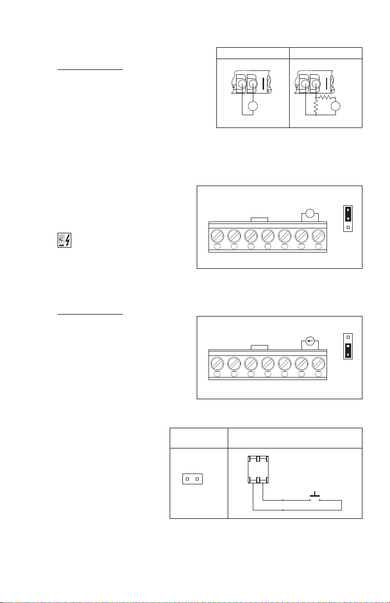
FIGURE 21 – MANUAL START SWITCH CONNECTION
Connector Installed for
Manual Start Switch
Application Note – In the Voltage
Following Mode, the input will
accept a “+” and “–“ input voltage, which will run the motor in
the forward and reverse direction.
Notes: 1. The MIN Trimpot on Models KBVF-45, 48 is not functional. Use the OFFSET Trimpot on
the SIVFR to offset the signal input, as described in Section 13.2.1, on page 23. 2. Do not use the
MAX Trimpot on Models KBVF-45, 48. Use the MAX Trimpot on the SIVFR to scale the signal input,
as described in Section 13.2.2.
19
Page 20
9.6 MANUAL START SWITCH
C
ON2
F - S - R
Forward-Stop-Reverse
Black
W
hite
CON2
R
ed
Stop
F
orward
R
everse
Switch
REV-5V
TB1
+5V 0V FWD SIG1 COM1
Forward Reverse
SIVF
TERMINAL
BLOCK
REV-5V
TB1
+5V 0V FWD SIG1 COM1
Forward Reverse
SIVF
TERMINAL
BLOCK
ONNECTION (CON1) – The
C
Manual Start Mode is used to
manually start the drive or restart
he drive (reset) if a fault has
t
ccurred. To operate the drive in
o
the Manual Start Mode, remove
the factory installed jumper on
ON1 and install the 2-wire
C
connector (supplied). CON1 is
located on the lower PC board.
he connector must be wired to a
T
omentary switch or contact, as
m
shown in Figure 21, on page 19.
In the Manual Start Mode, the drive will trip
due to all faults (Overvoltage,
Undervoltage, Short Circuit, and I
remain tripped even when the fault is
cleared. To Start/Reset the drive, the
switch or contact must be manually
closed. Also, the drive must be restarted
each time the AC line is interrupted.
For Automatic Start, see Section 6.2,
on page 15.
FIGURE 22 – FORWARD-STOP-REVERSE SWITCH CONNECTION
Jumper Removed
Connector Installed for
Forward-Stop-Reverse Switch
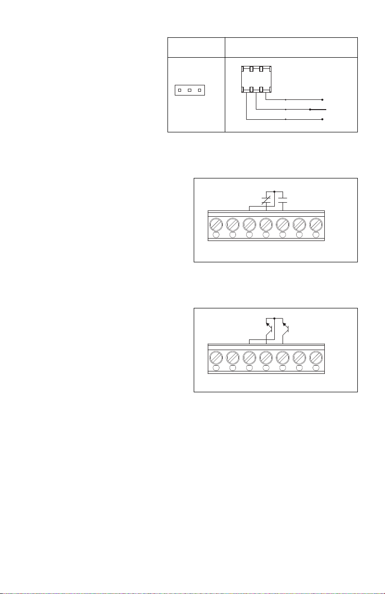
FIGURE 23 – FORM “C” CONTACT OR RELAY
FORWARD-STOP-REVERSE CONNECTION
2
t) and
Notes: 1. See Section 11.2, on page 22.
Also see Section 12.2, on page 23. 2. The
drive can be factory programmed for
Run/Stop operation with momentary contacts.
9.7 FORWARD-STOP-REVERSE SWITCH
CONNECTION (CON2) – The drive can
operate using a Forward-Stop-Reverse
Switch, Contact, or Open Collector.
9.7.1 Models KBVF-27, 29 – Remove
the factory installed jumper on
CON2 and install the 3-wire
connector (supplied). CON2 is located on the lower PC board. The connector must be wired to
a “maintained” switch or contact. See Figure 22. Also see Forward/Reverse Speed Selection, in
Section 6.3, on page 15.
If installing the SIFVR Signal Isolator, see Section 9.7.2.
Note: The drive can be factory programmed for momentary contact operation.
9.7.2 Models KBVF-45, 48 – Wire the Forward-Stop-Reverse Switch as shown in Figure 16, on
page 18. If using Form “C” Contact or Relay, wire the circuit as shown in Figure 23. If using
Open Collector, wire the circuit as shown in Figure 24.
9.8 ENABLE SWITCH CONNECTION (CON2) – The drive can be started and stopped with an Enable
Switch (close to run, open to stop). Remove the factory installed jumper on CON2 and install the 3wire connector (supplied). CON2 is located on the lower PC board. The connector must be wired to a
“maintained” switch or contact. See Figure 25, on page 21.
20
FIGURE 24 – OPEN COLLECTOR
FORWARD-STOP-REVERSE CONNECTION
Page 21
For Forward Enable Operation, wire the switch to the white and black wires. For Reverse Enable
J2
NC NOJ2NC NO
K1 K2
TB2
Run/Fault Relay Output Contacts
C
ON2
F
- S - R
(Close to Run)
R e d *
(Open to Stop)
Black
White
Enable Switch
CON2
Forward
(Close to Run)
Red
(
Open to Stop)
Black
White*
E
nable Switch
CON2
Reverse
peration, wire the switch to the red and black wires. When the switch is closed, the drive will run.
O
When the switch is opened, the drive will stop.
FIGURE 25 – ENABLE SWITCH CONNECTION
Jumper Removed
*For Forward Enable Switch connection, the red wire is not used. For Reverse Enable Switch connection, the white
wire is not used. The unused wire must be insulated or it may be cut off at the connector.
Connector Installed for
Forward Enable Switch
Connector Installed for
Reverse Enable Switch
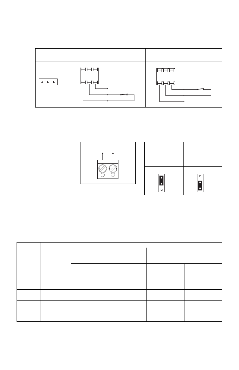
9.9 RUN/FAULT RELAY
– The Run/Fault
Relay is built-in on
Models KBVF-45, 48
and optional on
Models KBVF-27,
29. The Run/Fault
RUN/FAULT RELAY CONNECTION
FIGURE 26
FIGURE 27 – RUN/FAULT RELAY
OUTPUT CONTACT SELECTION
Normally Open Contacts Normally Closed Contacts
Jumper J2 Installed in
“NO” Position
(Factory Setting)
Jumper J2 Installed in
“NC” Position
Relay Output
Contacts are located
at TB2 of the SIVFR
and can be used to turn on or off equipment or to signal
a warning if the drive is put into the Stop Mode or a
fault has occurred. See Figure 26.
For normally open contacts, set Jumper J2 (on the SIVFR) to the “NO” position. For normally closed
contacts, set Jumper J2 (on the SIVFR) to the “NC” position. See Figure 27.
TABLE 4 – DRIVE OPERATING CONDITION AND RUN/FAULT RELAY CONTACT STATUS
Relay Contact Status (Terminals K1 and K2 of TB2)
Run Relay Operation
(Jumper J4 Installed in “RUN” Position)
(Factory Setting)
Drive
Operating
Condition
Power Off
Run Mode*
Stop Mode*
Fault** Drive Tripped Open Closed Open Closed
Description
Main Power
Disconnected
Normal
Drive Operation
Selected by
Operator
Jumper J2 Installed in
“NO” Position
(Factory Setting)
Open Closed Open Closed
Closed Open Closed Open
Open Closed Closed Open
Jumper J2 Installed in
“NC” Position
Jumper J2 Installed in
Fault Relay Operation
(Jumper J4 Installed in “FAULT” Position)
“NO” Position
(Factory Setting)
Jumper J2 Installed in
“NC” Position
*Run Mode or Stop Mode is selected using the Forward-Stop-Reverse Switch. ** Fault: Overload, I2t, Short Circuit, Undervoltage, and Overvoltage.
21
Page 22

10 AC LINE FUSING
his drive does not contain AC line fuses. Most electrical codes require that each ungrounded conductor
T
contain circuit protection. Do not fuse neutral or ground connections. It is recommended to install a fuse
(Littelfuse 326, Buss ABC, or equivalent) or a circuit breaker in series with each ungrounded conductor. Do
ot fuse motor leads. For the recommended fuse size, see Table 2, on page 11.
n
ire the drive in accordance with the National Electrical Code requirements and other local codes that may
W
apply to the application.
1 DRIVE OPERATION
1
1.1 START-UP PROCEDURE – After the drive has been properly setup (jumpers and trimpots set to the
1
desired positions) and wiring completed, the startup procedure can begin. If the AC power has been
properly brought to the drive, the power (PWR) LED will be illuminated green. The status (ST) LED will
ndicate drive status, as described in Section 11.2. To remove and install the Finger-Safe Cover, see
i
Section 5, on page 14.
11.2 FAULT RECOVERY – The drive monitors
four faults (Undervoltage, Overvoltage,
Short Circuit at the motor (phase-to-
2
phase), I
t). Table 5 describes how the
drive will automatically start (factory
setting) after the fault has cleared.
Application Note – In Manual Start
Mode, the drive must be manually
reset for any fault. Use the Manual
Start Switch, as described in Section
TABLE 5 – FAULT RECOVERY & RESETTING THE DRIVE*
F
ault
Undervoltage
Overvoltage
Short Circuit
I2t
*The fault must be cleared before the drive can be reset.
A
utomatic Start Mode (Factory Setting)
Drive will automatically start
after the bus voltage returns to the operational level
or when the drive is first turned on (power up).
Drive will automatically start
after the bus voltage returns to the operational level.
Drive will automatically start
after the short circuit is removed.
Drive must be manually restarted.
9.6, on page 20. Also see Section
12.2, on page 23.
11.3 RESTARTING THE DRIVE AFTER AN
2
I
t FAULT HAS CLEARED – The drive
can be restarted after an I
2
t Fault has
cleared by any of the following methods.
Note: If an I
2
t Fault occurs, the motor
may be overloaded. Check the motor
current with an AC RMS responding
ammeter. Also, the CL setting may be
set too low. See Section 13.7, on
pages 25 and 26.
1 Disconnect and reconnect the AC
power (approximately 15 seconds).
TABLE 6 – DRIVE OPERATING CONDITION &
STATUS LED INDICATOR
Drive Operating Condition
Normal Operation (Run) Slow Flash Green
Overload (120% – 160% Full Load)
I2t (Drive Timed Out)
Short Circuit Slow Flash: Red
Undervoltage
Overvoltage
Stop Steady Yellow
Notes: 1. Slow Flash = 1 second on and 1 second off. Quick Flash = 0.25
second on and 0.25 second off. 2. In Manual Start Mode, when the Overload
is removed, before the I
flash green. 3. In Manual Start Mode, when the Undervoltage or Overvoltage
condition is corrected, the “ST” LED will flash Red / Yellow / Green.
2
t times out and trips the drive, the “ST” LED will
Flash Rate1and LED Color
Steady Red
Quick Flash Red
Quick Flash Red / Yellow
Slow Flash Red / Yellow
The “ST” LED must change from quick flashing red to flashing red/yellow.
2
3
3
2 Setting the Main Speed Potentiometer to zero (fully counterclockwise).
Note: In order to be able to reset the drive by setting the Main Speed Potentiometer to zero, it is
necessary to have the MIN Trimpot set to zero (fully counterclockwise).
3 Open and close the Enable switch or contact. See Section 9.8, on pages 20 and 21.
12 DIAGNOSTIC LEDS
The drive contains two diagnostic LEDs to display the drive’s operational status. See Figure 5, on page 13,
for the location of the “PWR” and “ST” LEDs.
22
Page 23
12.1 POWER ON (PWR) – The “PWR” LED will illuminate green when the AC line is applied to the drive.
30
MIN
(Shown Factory Set to 0% Frequency Setting)
0
15
40
35
80
(Shown Factory Set to 100% Frequency Setting)
MAX
70
75
100
110
90
OFFSET
-
+
ADJUST
2.2 STATUS LED (ST) – The “ST” LED is a tricolor LED which provides indication of a fault or abnormal
1
ondition. The information provided can be used to diagnose an installation problem such as incorrect
c
input voltage, overload condition, and drive output miswiring. It also provides a signal which informs
the user that all drive and microcontroller operating parameters are normal. Table 6, on page 22,
ummarizes the “ST” LED functions.
s
Note: The drive is factory set to the Automatic Start Mode. For Manual Start/Reset, see Section 9.6,
n page 20.
o
13 TRIMPOT ADJUSTMENTS
he drive contains trimpots which are factory set for most applica-
T
ions. See Figure 5, on page 13, for the location of the trimpots
t
and their approximate factory calibrated positions. Some applications may require readjustment of the trimpots in order to tailor the
drive for a specific requirement. The trimpots may be
readjusted as described below.
WARNING! If possible, do not adjust trimpots with
with the main power applied, an insulated adjustment tool
must be used and safety glasses must be worn. High voltage
exists in this drive. Fire and/or electrocution can result if caution is
not exercised. Safety Warning, on pages 8 and 9, must be read and
understood before proceeding.
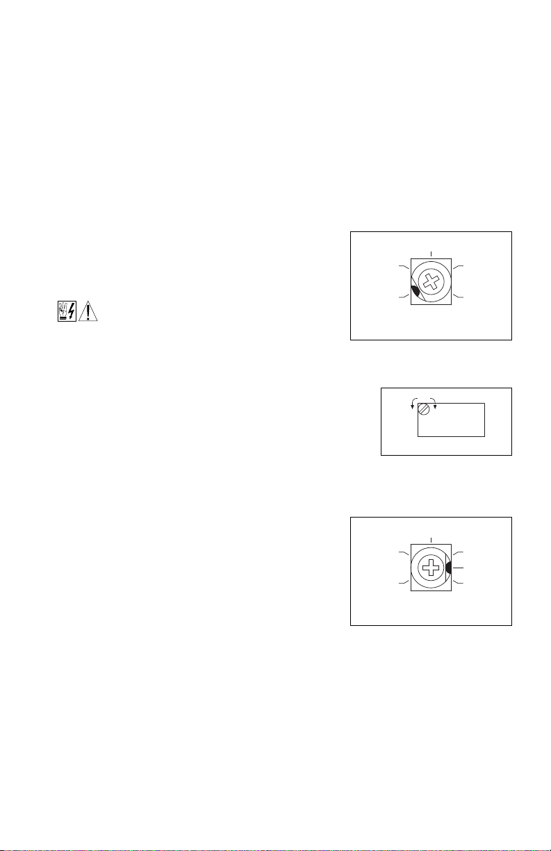
13.1 MINIMUM SPEED (MIN / OFFSET) – Sets the minimum speed of
the main power applied. If adjustments are made
the motor.
13.1.1 Models KBVF-27, 29 – The MIN Trimpot is factory set to
0% of frequency setting. For a
higher minimum speed setting, rotate the MIN
Trimpot clockwise. See Figure 28.
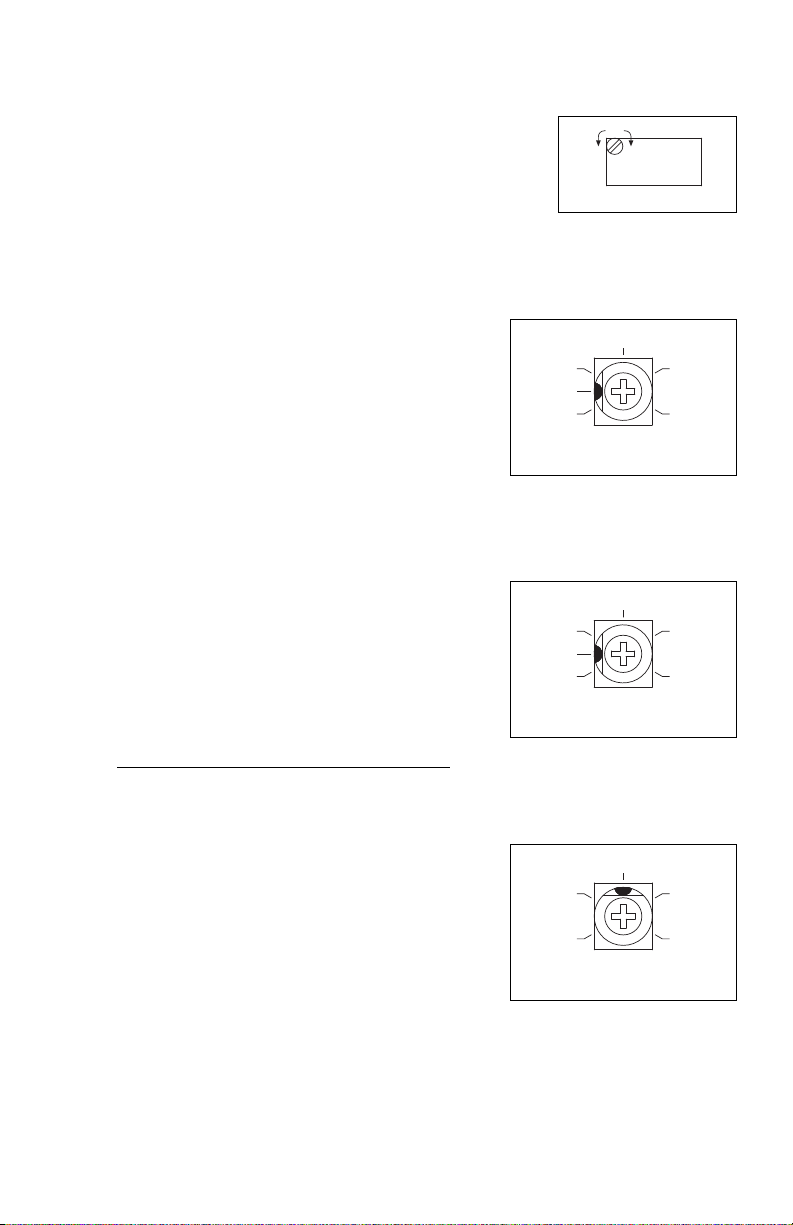
13.1.2 Models KBVF-45, 48 – The OFFSET Trimpot on the
SIVFR is a 10-turn trimpot which allows for accurate
setting of the minimum speed of the motor. The
OFFSET Trimpot is factory set to 0% of frequency
setting. For a higher minimum speed setting, rotate
the OFFSET Trimpot clockwise. See Figure 29.
FIGURE 28 – MINIMUM SPEED
TRIMPOT RANGE
MODELS KBVF-27, 29
FIGURE 29 – OFFSET TRIMPOT
MODELS KBVF-45, 48
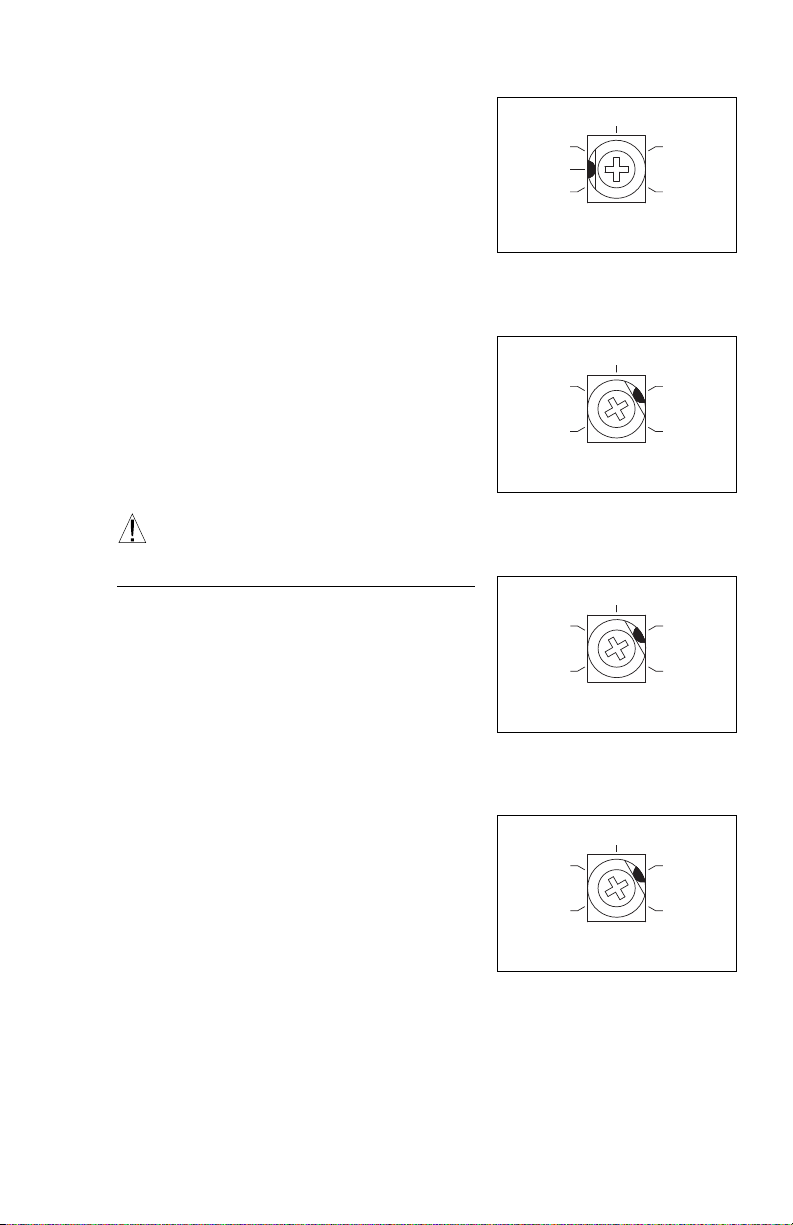
FIGURE 30 – MAXIMUM SPEED
TRIMPOT RANGE
MODELS KBVF-27, 29
Note: The MIN Trimpot on Models KBVF-45, 48 is
not functional.
13.2 MAXIMUM SPEED (MAX) – Sets the maximum speed
of the motor.
13.2.1 Models KBVF-27, 29 – The MAX Trimpot is factory
set to 100% of frequency setting. For a higher
maximum speed setting, rotate the MAX Trimpot clockwise. For a lower maximum speed setting, rotate the MAX Trimpot counterclockwise. See Figure 30.
13.2.2 Models KBVF-45, 48 – The MAX Trimpot on the SIVFR is a 10-turn trimpot which allows for
accurate setting of the maximum speed of the motor. The MAX trimpot is factory set to 100%
of frequency setting. For a higher maximum speed setting, rotate the MAX Trimpot clockwise.
For a lower maximum speed setting, rotate the MAX Trimpot counterclockwise. See Figure 31,
23
Page 24
on page 24.
MAX
-
+
ADJUST
(Shown Factory Set to 1.5 Seconds)
1.5
.3
3
ACC
20
10
17
(Shown Factory Set to 1.5 Seconds)
1.5
.3
3
DEC/B
20
10
17
(Shown Factory Set to 1.5 Volts/Hz)
COMP
0 3
.8
1.5
2.3
3.3 ACCELERATION (ACC) – Sets the amount of time for the motor to
1
ccelerate from zero speed to full speed. The ACC Trimpot is factory
a
set to 1.5 seconds. For longer acceleration time, rotate the ACC
Trimpot clockwise. For more rapid acceleration, rotate the ACC
rimpot counterclockwise. See Figure 32.
T
Note: Rapid acceleration settings may cause the current limit circuit
o activate, which will extend the acceleration time.
t
FIGURE 31 – MAXIMUM
SPEED TRIMPOT
ODELS KBVF-45, 48
M
13.4 DECELERATION (DEC/B) – Sets the amount of time for
he motor to decelerate from full speed to zero speed. The
t
DEC/B Trimpot is factory set to 1.5 seconds. For longer
deceleration time, rotate the DEC/B Trimpot clockwise. For
more rapid deceleration, rotate the DEC/B Trimpot counterclockwise. See Figure 33.
Application Note – On applications with high inertial loads,
the deceleration may automatically increase in time. This will
slow down the rate of speed of decrease to prevent the bus
voltage from rising to the Overvoltage Trip point. This function
is called Regeneration Protection. It is recommended that
for very high inertial loads that both the ACC and DEC/B
Trimpots should be set to greater than 10 seconds.
For rapid stopping, install the optional DBVF – Dynamic
Brake Module (Part No. 9598). See Section 3.5, on page 10.
13.5 SLIP COMPENSATION (COMP) – Sets the amount of
Volts/Hz to maintain set motor speed under varying loads.
The COMP Trimpot is factory set to 1.5 Volts/Hz, which
provides excellent speed regulation for most motors. To
increase the slip compensation, rotate the COMP Trimpot
clockwise. To decrease the slip compensation, rotate the
COMP Trimpot counterclockwise. See Figure 34.
The slip compensation may be adjusted as follows:
1. Wire an AC RMS ammeter in series with one motor
phase.
2. Run the motor and set the unloaded speed to approxi-
mately 50% (900 RPM on 4-pole 1500/1725 RPM
motors).
FIGURE 32 – ACCELERATION
TRIMPOT RANGE
ALL MODELS
FIGURE 33 – DECELERATION
TRIMPOT RANGE
ALL MODELS
FIGURE 34 – SLIP COMPENSATION
TRIMPOT RANGE
ALL MODELS
3. Using a tachometer, record the unloaded speed.
4. Load the motor to the nameplate rated current (AC
Amps).
5. Adjust the COMP Trimpot until the loaded RPM is equal to
the unloaded RPM.
6. The motor is now compensated to provide constant speed under varying loads.
24
Page 25
13.6 BOOST (DEC/B) – When the drive is set for 50 Hz Motor
(Shown Factory Set to 5 Volts/Hz)
5
D
EC/B
0 30
8
15
23
(Shown Factory Set to 10.7 Amps)
4.0
CL
12.5
6.1
8.3
10.7
(Shown Factory Set to 14.4 Amps)
17.05.5
CL
7.4
9.8
14.4
(Shown Factory Set to 7.4 Amps)
8.53.0
CL
4.4
5.8
7.4
peration (Jumper J1 installed in the “50Hz” position), the
O
DEC/B Trimpot automatically becomes the adjustable
BOOST Trimpot.
Most 60 Hz motors conforming to NEMA standards can
perate from a preset Volts/Hz curve. 50 Hz motors, how-
o
ever, generally differ widely in their characteristics.
Therefore, it is necessary to have adjustable Boost to
btain maximum motor performance.
o
To increase the boost, rotate the BOOST Trimpot clock-
ise. To decrease the boost, rotate the BOOST Trimpot
w
ounterclockwise. See Figure 35.
c
In order for the 50 Hz motor to run properly, the boost
must be adjusted. If the application does not require full
torque below 10 Hz, the Boost (DEC/B) Trimpot can be
conservatively set at 8% (9 o’clock position).
Note: In 50 Hz motor operation, the deceleration time is
automatically set to the same as the Acceleration Trimpot
(ACC) setting.
WARNING! To avoid motor winding heating and
failure, do not overboost the motor.
The Boost (DEC/B)Trimpot may be adjusted as follows:
1. Wire an AC RMS ammeter in series with one motor
phase.
FIGURE 35 – BOOST TRIMPOT RANGE
ALL MODELS
FIGURE 36 – CL TRIMPOT RANGE
MODEL KBVF-27
FIGURE 37 – CL TRIMPOT RANGE
MODEL KBVF-29
2. Run the motor unloaded at approximately 4 Hz
(or 120 RPM).
Note: An unloaded motor with excessive boost will
draw more current than a partially loaded motor.
3. Increase the boost until the ammeter reaches the
nameplate rated current (Amps AC).
4. Using the Main Speed Potentiometer, slowly adjust the
motor speed over a 0 – 15 Hz (0 – 450 RPM) range. If
the motor current exceeds the nameplate rating,
decrease the boost setting.
13.7 MOTOR OVERLOAD (I
(CL)* – Sets the current limit (overload), which limits the
maximum current to the motor, prevents motor burnout,
and eliminates nuisance trips. The CL Trimpot is factory set
to 160% of the drive rated current. To increase the current limit, rotate the CL Trimpot clockwise.
To decrease the current limit, rotate the CL Trimpot counterclockwise. See Figures 36 – 39,
on pages 25 and 26.
*UL approved as an electronic overload protector for motors.
In order to ensure that the motor is properly protected with the I
CL Trimpot be set for 160% of the motor nameplate rating. This is accomplished as follows:
2
t) WITH RMS CURRENT LIMIT
FIGURE 38 – CL TRIMPOT RANGE
MODEL KBVF-45
2
t feature, it is required that the
25
Page 26

Note: This adjustment must be made within 6 seconds or
(Shown Factory Set to 13.3 Amps)
15.55.0
CL
7.6
10.3
13.3
2
he I
Trip will occur.
t
t
. Connect an AC RMS ammeter in series with one motor
1
phase.
2. Set the CL Trimpot fully counterclockwise.
. Adjust the speed setting to 30% of full speed.
3
. Lock the motor shaft and adjust the CL Trimpot to 160%
4
of the motor nameplate rated current.
Example: A 2 HP motor has a full load current rating of 5.2 Amps. Set the CL Trimpot to 5.2 X
160% = 8.3 Amps
FIGURE 39 – CL TRIMPOT RANGE
MODEL KBVF-48
26
Page 27

– NOTES –
27
Page 28

For a period of 18 months from the date of original purchase, KB Electronics, Inc. will repair or replace
LIMITED WARRANTY
without charge, devices which our examination proves to be defective in material or workmanship. This
warranty is valid if the unit has not been tampered with by unauthorized persons, misused, abused, or
improperly installed and has been used in accordance with the instructions and/or ratings supplied. The
foregoing is in lieu of any other warranty or guarantee, expressed or implied. KB Electronics, Inc. is not
responsible for any expense, including installation and removal, inconvenience, or consequential damage,
including injury to any person, caused by items of our manufacture or sale. Some states do not allow certain exclusions or limitations found in this
warranty and therefore they may not apply to you. In any event, the total liability of KB Electronics, Inc.
under any circumstance, shall not exceed the full purchase price of this product. (rev 2/2000)
COPYRIGHT © 2005 KB Electronics, Inc.
All rights reserved. In accordance with the United States Copyright Act of 1976, no part of this publication
may be reproduced in any form or by any means without permission in writing from KB Electronics, Inc.
(8/2002)
KB ELECTRONICS, INC.
12095 NW 39th Street, Coral Springs, FL 33065-2516 • (954) 346-4900 • FAX (954) 346-3377
Outside Florida Call Toll Free (800) 221-6570 • info@kbelectronics.com
www.kbelectronics.com
(A40388) – Rev. B – 6/2006
Print Code
Page 29

RECONDITIONING THE BUS CAPACITORS
If this drive has been in storage for over one year it
is necessary to recondition the power supply bus
capacitors. To recondition the bus capacitors, apply
the AC Line, with the drive in the Stop Mode, for a
minimum of one hour. Not following this procedure
will cause the bus capacitors to fail.
(A40194) – Rev. A00 – 7/31/2013
 Loading...