

Page 1
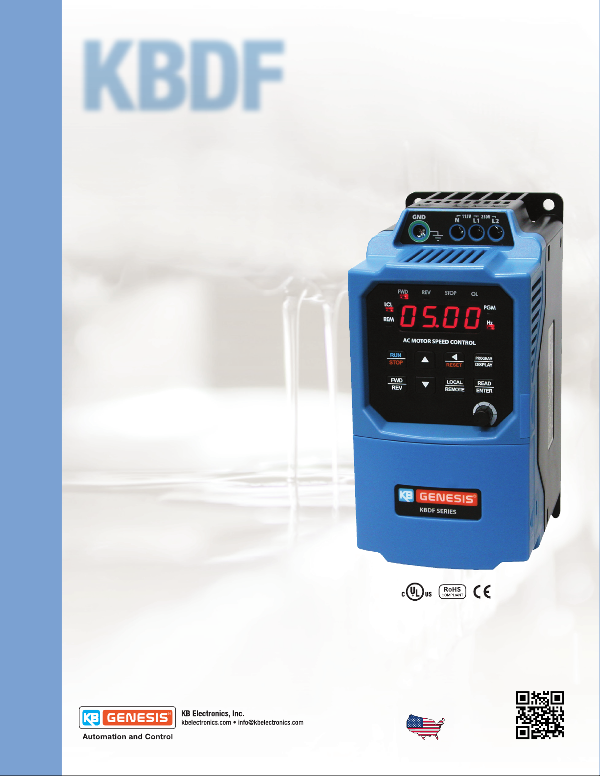
KBDF
Digital AC Drive with CSP
IP 20 Enclosure
Primary Features
Horsepower 1/8 to 5 HP, Programmable
115/230/460 VAC - 1ph & 3ph Input
Output 230/460 VAC - 3ph
Starting Torque 200%
Digital Display with LED Status Indicators
Class “A” (CE) RFI Filter**
Benefits
Saves Time
Easy to Install and Simple to Operate
Does not require commissioning
With CSP™ you are up and running in less than 10 minutes.
Motors Last Longer
Proprietary CL Software
Provides overload protection, prevents motor burnout
and eliminates nuisance tripping.
UL approved as electronic overload protector for motors.
™*
Energy Saving
Uses only the power the application requires
Replacing constant speed with variable speed will
significantly reduce energy cost.
Economical to Use
No need to derate drive for high starting torque applications.
Combines Soft Start with Variable Speed
Adjustable Soft Start.
Customization for OEM’s
When an off the shelf drive does not meet your needs, KB will work with you
to provide a custom drive solution, Ready to Use, “Out-of-the-Box.”
Customization includes: Pre-calibrating or programming of a stock control,
adding a custom label or branding, custom software, PLC functions or designing a new control.
GFCI Software allows the equipment to operate with Ground Fault
Circuit Interruption circuit breakers or outlets.
*CSP™ = Common Sense Programming. Parameters are organized into easy-to-understand intuitive groups.
**Order “F” suffix for built in filter. KBDF-24F.
Designed and
Assembled in USA
Page 2
2
Additional Features
Sensorless Flux Vector Control
Flux Vector Compensation with Static Auto-Tune provides excellent speed regulation
with high torque loads throughout the entire speed range. Auto energy saving at light
loads. Smooth motor torque.
Local/Remote Operation
When used with process control, the Local /Remote key can be used to switch from
process control to manual control if a process fault occurs.
Electronic Inrush Current Limit (EICL™) Protection
Eliminates harmful inrush AC line current during power up.
Inputs/Outputs
Seven isolated multi-function inputs with sink or source mode control logic, two
analog inputs, two multi-function output relays and one analog output.
Built-in Potentiometer
Sets motor speed in lieu of keypad.
Ride-Through
Provides smooth recovery to the previous set speed during a momentary power loss.
Holding Torque at Zero Speed
Resists motor shaft rotation when the drive is in “Stop” mode.
Regeneration Protection
Eliminates tripping due to high bus voltage caused by rapid deceleration of high
inertial loads.
Undervoltage and Overvoltage Protection
Shuts down the drive if the AC line input voltage goes above or below
the operating range.
Short Circuit Protection
Shuts down the drive if a short circuit occurs at the motor (phase-to-phase).
Drive Options
Memory Module
The Memory Module can store up to four programs for cloning and archiving.
The drive can also store up to four programs.
IODF Input/Output Multi-Function Expansion Module
Adds up to 5 points of additional I/O.
Drive-Link™ Programming Kit
Allows PC programming.
Modbus Serial Communication Module
See instruction manual for complete description.
D-1030
Applications
• Actuators • Air Cleaners • Amusement Rides
• Ball Pitching Machines • Blowers • Boat Lifts
• Bowling Alley Lane Cleaners • CNC • Conveyors
• Door and Gate Openers • Drilling • Duct Cleaners
• Dumbwaiters • Elevators and Hoists
• Exercise Equipment • Fabric Processing • Fans
• Feeders • Film Processing • Floor Cleaning
• Food Processing • Garment Cutting
• Grinding and Polishing • Hoppers • Horse Walkers
• HVAC • Indexers • Irrigation • Laminating
• Lift Station Pumps • Machine Tools
• Medical • Milling • Mixers • Oven Conveyors
• Packaging • Paint Blenders, Shakers, and Sprayers
• Paper Handling • Portable Equipment Used with GFCIs
• Pottery Wheels • Printing
• Pumps • Range Hoods • Sandblasting • Saws
• Sewing • Stretch Wrap • Textile • Treadmills
• Therapeutic Vibrators • Washing Machines
• Wave Soldering • Web Processing • Wheelchair Lifts
• Whole House Vacuums and Attic Fans
• Wire Feeders • Wood and Metal Lathes and Cut ters
• Winders and Unwinders
Visit kbelectronics.com
to learn about Build-A-Drive™ , KB’s New AC Inverter Program.
Page 3

Case “B” – (Inches/mm)
4.4
112
Maximum Depth:
6.1
155
Case “A” – (Inches/mm)
7.8
199
D-1030
Ratings
115 VAC 1-Phase Input • 230 VAC 3-Phase Output
Ratings
Model No. Part No.
KBDF-13 9623 0.5, (0.37) 2.4 2.8 1.27
KBDF-14 9624 1, (0.75) 4.0 2.8 1.27
KBDF-16 9625 1.5, (1.2) 5.5 2.8 1.27
HP, (kW) Amps
115/230 VAC 1-Phase Input • 230 VAC 3-Phase Output
Ratings Net Weight
Model No. Part No.
KBDF-23D 9673 0.5, (0.37) 2.4 2.8 1.27
KBDF-24D 9674 1, (0.75) 4.0 2.8 1.27
KBDF-27D* 9675 2, (1.5) 6.7 2.8 1.27
*115 VAC Rating: 1.5 HP, (1.2 kW), 5.5 Amps
HP, (kW) Amps
230 VAC 1-Phase Input • 230 VAC 3-Phase Output
Ratings Net Weight
Model No. Part No.
KBDF-23** 9688 0.5, (0.37) 2.4 2.8 1.27
KBDF-24** 9689 1, (0.75) 4 2.8 1.27
KBDF-27** 9690 2, (1.5) 6.7 2.8 1.27
KBDF-29 (1P) 9700 3, (2.25) 9 4.2 1.93 B
HP, (kW) Amps
230 VAC 3-Phase Input • 230 VAC 3-Phase Output
Ratings Net Weight
Model No. Part No.
KBDF-29** 9641 3, (2.25) 9 4.2 1.93 B
Net Weight
Lbs. kg
Lbs. kg
Lbs. kg
3
Case
A
Case
A
Case
A
CaseHP, (kW) Amps Lbs. kg
3.4
86.4
Maximum Depth:
5.1
130
7.25
184
460 VAC 3-Phase Input • 460 VAC 3-Phase Output
Ratings Net Weight
Model No. Part No.
KBDF-42** 9642 1, (0.75) 2.0 4.2 1.93
KBDF-45** 9643 3, (2.25) 5.5 4.2 1.93
KBDF-48** 9644 5, (3.75) 8.3 4.2 1.93
**Order “F” Suffix for Built-In Class “A” (CE) RFI (EMI) AC Line Filter. Ex. KBDF-24F
Specifications
Maximum Load (% of Current Overload for 2 Minutes) 150
Switching Frequency (kHz) 8, 10, 12, 14, 16
Output Frequency Resolution (Hz) 0.06
Minimum Output Frequency to Motor (Hz) 0.3
Acceleration Time (Seconds) 0.1 – 180.0
Deceleration Time (Seconds) 0.3 – 180.0
Speed Range (Ratio) 50:1
Speed Regulation (30:1 Speed Range, 0 – Full Load) (% Base Speed) 2.5
Stalled Motor Trip Time (Seconds) 6
Braking DC Injection
Operating Temperature Range (ºC / ºF) 0 – 40 / 32 – 104
Storage Temperature (ºC / ºF) -25 – +85 / -13 – +185
CaseHP, (kW) Amps Lbs. kg
B
Page 4

General Connection Diagram
D-1030
AC Line Input
(Varies by Model)
Ground (Earth)
Remote
Main Speed
Potentiometer
(5k Ohm Min.)
Multi-Function
Input Terminals
(MFIT 1 - 5)
1
L1
L2
L3 / N
GND
(Chassis)
TB1
-5 Volts DC
1
(1 mA Max.)
+5 Volts DC
2
(1 mA Max.)
Analog Signal Input
3
(0 - ±5 / ±10 Volts DC, 0 - 20 / 4 - 20 mA DC)
Common
4
5
MFIT 1
MFIT 2
6
MFIT 3
7
8
MFIT 4
9
MFIT 5
Signal Input
Scaling Trimpot
Multi-Function
Open Collector Output
U
V
W
GND
(Chassis)
TB2
N.O.
COM
N.C.
N.O.
COM
N.C.
TB3
TB1
13
Motor
Ground (Earth)
Ground (Earth)
Multi-Function
Output Relay
2
Contacts
Multi-Function
Output Relay
2
10
5 - 24 Volts DC Input
14MFIT 6
Multi-Function
Input Terminals
(MFIT 6 - 7)
3
Multi-Function Input
Type Selection
Signal Input
Type Selection
11 Common
Analog Output
12
(0 - 5 Volts DC)
N.O. / NPN
EXTCUR
J1
VOLT PNP
ANLG
PWM
10V
5V
J2
MFIT 7
Common
+5 Volts DC
(1 mA Max.)
0 - 25 Volts DC
Signal Input
Common
15
16
17
18
19
Optional
IODF Input/Output
Multi-Function Expansion Module
Shield (Connect to GND Terminal)
Not es : 1. Multi-Function Input Terminals (MFIT 1 – 5 on TB1of the drive) are factory set for N.O. Contacts or NPN Transistors (J1 set to the “N.O. / NPN” position), which use the internal
power supply. For NPN Transistors, which use an external power supply (5 – 24 Volts DC ), set Jumper J1 to the “EXT” position. For PNP Transistor circuits, which use the internal power
supply or an external power supply (5 – 24 Volts DC ), set Jumper J1 to the “PNP” position. 2. Multi-Function Output Relay Contact Ratings : 1 Amp at 30 Volts DC, 0.5 Amp at 125 Volts AC,
and 0.25 Amp at 250 Volts AC. 3. Multi-Function Input Terminals ( MFIT 6 – 7 on TB4 of the IODF) only accept N.O. Contacts or NPN Transistors (which use the internal power supply).
Represented by:
KB ELECTRONICS, INC.
(954) 346-4900 • Fax (954) 346-3377
Outside Florida Call Toll Free (800) 221-6570
info@kbelectronics.com • www.kbelectronics.com
A42046 – Rev. H – 05/2013
 Loading...