


ZZR1400 2016 - 2019
Table of contents
 Loading...
ZZR1400 ABS
Ninja ZX-14R
Ninja ZX-14R ABS


This quick reference guide will assist
you in locating a desired topic or pro-
cedure.
•Bend the pages back to match the
black tab of the desired chapter num-
ber with the black tab on the edge at
each table of contents page.
•Refer to the sectional table of contents
for the exact pages to locate the spe-
cific topic required.
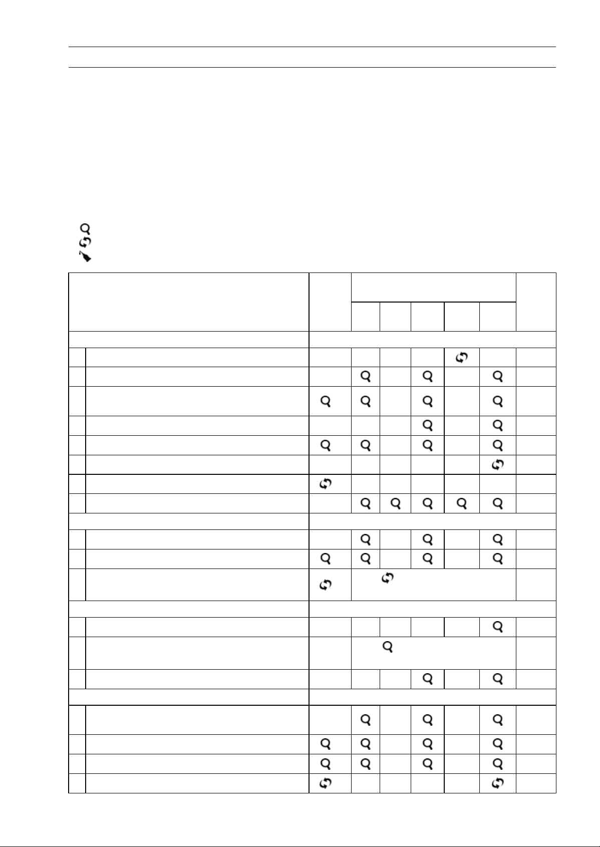
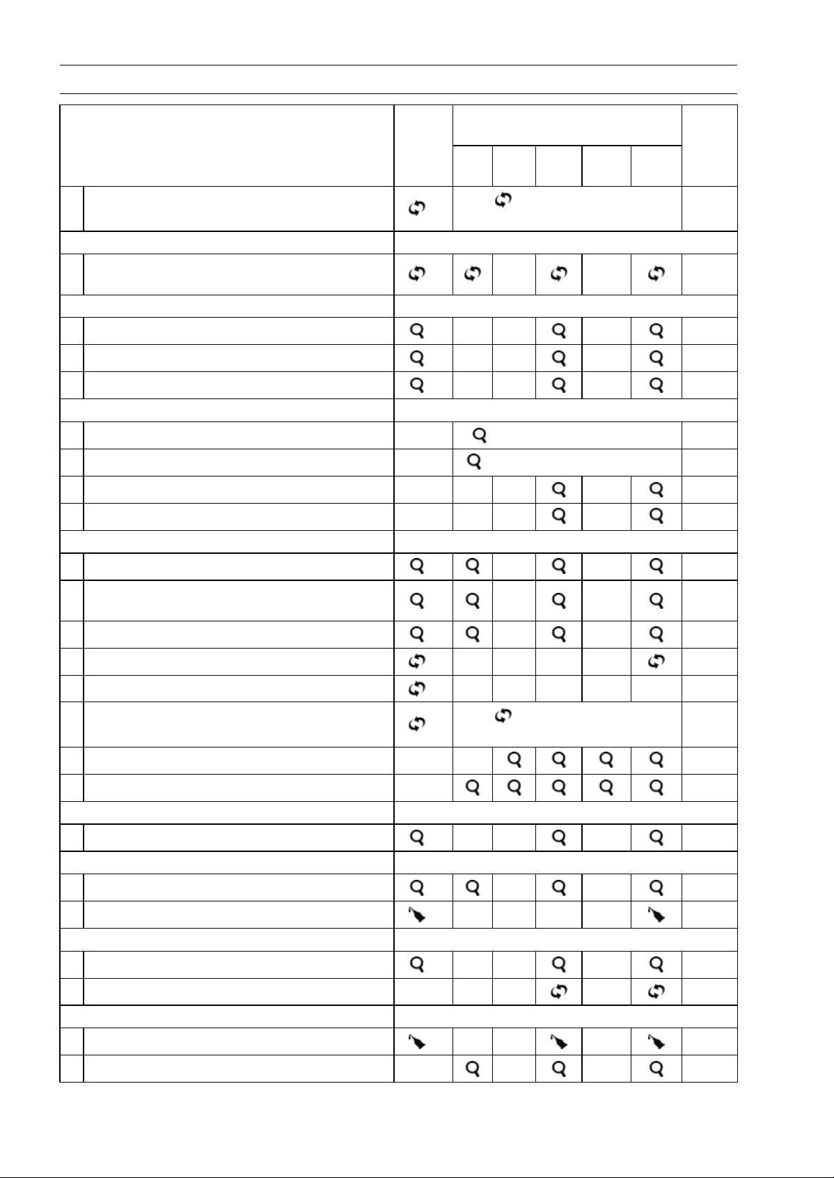
Quick Reference Guide
General Information 1 j
Periodic Maintenance 2 j
Fuel System (DFI) 3 j
Cooling System 4 j
Engine Top End 5 j
Clutch 6 j
Engine Lubrication System 7 j
Engine Removal/Installation 8 j
Crankshaft/Transmission 9 j
Wheels/Tires 10 j
Final Drive 11 j
Brakes 12 j
Suspension 13 j
Steering 14 j
Frame 15 j
Electrical System 16 j
Appendix 17 j


ZX1400H/J
Motorcycle
Service Manual
All rights reserved. No parts of this publication may be reproduced, stored in a retrieval system, or
transmitted in any form or by any means, electronic mechanical photocopying, recording or otherwise,
without the prior written permission of Quality Assurance Division/Motorcycle & Engine Company/Kawasaki
Heavy Industries, Ltd., Japan.
Copyright © 2015 Kawasaki Heavy Industries, Ltd. Fourth Edition (0) : May 17, 2018

LIST OF ABBREVIATIONS
A
ampere(s) in. inch(es)
ABDC after bottom dead center ISC
idle speed control
ABS antilock brake system
JASO Japanese Automotive Standards
Organization
AC alternating current km/h kilometers per hour
Ah ampere hour L liter(s)
API American Petroleum Institute lb pound(s)
ATDC after top dead center LCD liquid crystal display
BBDC before bottom dead center LED light emitting diode
BDC bottom dead center m meter(s)
BTDC before top dead center
min
minute(s)
°C degree(s) celsius
mmHg
millimeters of mercury
cmHg
centimeters of mer
cury
mph miles per hour
CPU central processing unit N newton(s)
cu in. cubic inch(es) oz ounce(s)
DC direct current Pa pascal(s)
DFI digital fuel injection PS horsepower
DOHC double overhead camshaft psi pound(s) per square inch
DOT Department of Transportation qt quart(s)
ECU electronic control unit r revolution
F farad(s) rpm revolution(s) per minute
°F degree(s) fahrenheit
s
second(s)
FI fuel injection SAE Society of Automotive Engineers
ft foot, feet TDC top dead center
g gram(s) TIR total indicator reading
gal gallon(s) V volt(s)
h hour(s) W watt(s)
HP horsepower(s) ohm(s)
IC
integrated circuit
COUNTRY AND AREA CODES
AT Austria IN India
AU Australia MY Malaysia
CA Canada PH Philippines
CAL California SEA-B1 Southeast Asia B1
CH Switzerland SEA-B3 Southeast Asia B3
CN China
TH Thailand
DE Germany US United States
EUR Europe
WVTA
(FULL)
WVTA Model (Full Power)
GB
United Kingdom
GB WVTA
(FULL)
GB WVTA Model (Full Power)
ID Indonesia

EMISSION CONTROL INFORMATION
To protect the environment in which we all live, Kawasaki has incorporated crankcase emis-
sion (1) and exhaust emission (2) control systems in compliance with applicable regulations of
the United States Environmental Protection Agency and California Air Resources Board. Addi-
tionally, Kawasaki has incorporated an evaporative emission control system (3) in compliance
with applicable regulations of the California Air Resources Board on vehicles sold in California
only.
1. Crankcase Emission Control System
This system eliminates the release of crankcase vapors into the atmosphere. Instead, the vapors
are routed through an oil separator to the intake side of the engine. While the engine is operating,
the vapors are drawn into combustion chamber, where they are burned along with the fuel and air
supplied by the fuel injection system.
2. Exhaust Emission Control System
This system reduces the amount of pollutants discharged into the atmosphere by the exhaust
of this motorcycle. The fuel, ignition, and exhaust systems of this motorcycle have been carefully
designed and constructed to ensure an efficient engine with low exhaust pollutant levels.
The exhaust system of this model motorcycle manufactured primarily for sale in California in-
cludes a catalytic converter system.
3. Evaporative Emission Control System
Vapors caused by fuel evaporation in the fuel system are not vented into the atmosphere. In-
stead, fuel vapors are routed into the running engine to be burned, or stored in a canister when
the engine is stopped.
The Clean Air Act, which is the Federal law covering motor vehicle pollution, contains what is
commonly referred to as the Act’s “tampering provisions”.
“Sec. 203(a) The following acts and the causing thereof are prohibited...
(3)(A) for any person to remove or render inoperative any device or element of design installed
on or in a motor vehicle or motor vehicle engine in compliance with regulations under this
title prior to its sale and delivery to the ultimate purchaser, or for any manufacturer or dealer
knowingly to remove or render inoperative any such device or element of design after such
sale and delivery to the ultimate purchaser.
(3)(B) for any person engaged in the business of repairing, servicing, selling, leasing, or trading
motor vehicles or motor vehicle engines, or who operates a fleet of motor vehicles know-
ingly to remove or render inoperative any device or element of design installed on or in a
motor vehicle or motor vehicle engine in compliance with regulations under this title follow-
ing its sale and delivery to the ultimate purchaser...”
NOTE
○
The phrase “remo ve or render inoperative any device or element of design” has been generally
interpreted as follows.
1. Tampering does not include the temporary removal or rendering inoperative of de-
vices or elements of design in order to perform maintenance.
2. Tampering could include.
a.Maladjustment of vehicle components such that the emission standards are ex-
ceeded.
b.Use of replacement p arts or accessories which adversely affect the performance
or durability of the motorcycle.
c.Addition of components or accessories that result in the vehicle exceeding the stan-
dards.
d.Permanently removing, disconnecting, or rendering inoperative any component or
element of design of the emission control systems.
WE RECOMMEND THAT ALL DEALERS OBSERVE THESE PROVISIONS OF FEDERAL
LAW, THE VIOLATION OF WHICH IS PUNISHABLE BY CIVIL PENALTIES NOT EXCEEDING
$10 000 PER VIOLATION.

TAMPERING WITH NOISE CONTROL SYSTEM PROHIBITED
Federal law prohibits the following acts or the causing thereof. (1) The removal or rendering
inoperative by any person other than for purposes of maintenance, repair, or replacement, of any
device or element of design incorporated into any new vehicle for the purpose of noise control
prior to its sale or delivery to the ultimate purchaser or while it is in use, or (2) the use of the
vehicle after such device or element of design has been removed or rendered inoperative by
any person.
Among those acts presumed to constitute tampering are the acts listed below.
•
Replacement of the original exhaust system or muffler with a component not in compliance
with Federal regulations.
•
Removal of the muffler(s) or any internal portion of the muffler(s).
•
Removal of the air box or air box cover.
•
Modifications to the muffler(s) or air intake system by cutting, drilling, or other means if such
modifications result in increased noise levels.
Foreword
(About this manual)
This service manual explains maintenance pro-
cedures for removing, installing, disassembling,
assembling, and adjusting, as necessary, in-
cluding periodic inspection and maintenance of
major parts of recording models.
(Disclaimer)
1. This book does not describe all the matters
concerning maintenance. This book is made
for people who have basic skills and knowl-
edge on maintenance of Kawasaki products
(authorized Kawasaki dealers or other re-
pairers). So those who do not have these
skills and knowledge do not do maintenance
or inspection with this manual. Skill short-
age and lack of knowledge may cause main-
tenance troubles, parts breakage, etc.
2. All information contained in this publication
is based on the latest product information
available at the time of publication. No liabil-
ity can be accepted for any inaccuracies or
omissions in this publication, although every
possible care has been taken to make it as
complete and accurate as possible.
3. Illustrations and photographs in this publi-
cation are intended for reference use only
and may not depict actual model component
parts.
4. The right is reserved to make changes at any
time without prior notice and without incur-
ring an obligation to make such changes to
products manufactured previously. Please
accept beforehand that the description con-
tent, illustration, photographs etc. may differ
from actual vehicle due to vehicle specifica-
tion change.
5. The content of the description may be
changed without prior notice for vehicle
specification change etc.
How to Use This Manual
In this manual, the product is divided into
its major systems and these systems make up
the manual’s chapters. The Quick Reference
Guide shows you all of the product’s system
and assists in locating their chapters. Each
chapter in turn has its own comprehensive Ta-
ble of Contents.
For example, if you want stick coil information,
use the Quick Reference Guide to locate the
Electrical System chapter. Then, use the Table
of Contents on the first page of the chapter to
find the Stick Coil section.
Whenever you see symbols, heed their in-
structions! Always follow safe operating and
maintenance practices.
DANGER
DANGER indicates a hazardous situa-
tion which, if not avoided, will result in
death or serious injury.
WARNING
WARNING indicates a hazardous situa-
tion which, if not avoided, could result
in death or serious injury.
NOTICE
NOTICE is used to address practices not
related to personal injury.
This manual contains four more symbols
which will help you distinguish different types
of information.
NOTE
○
NOTE indicates information that may help
or g uide you in the operation or service of
the vehicle.
•
Indicates a procedural step or work to be
done.
Indicates a procedural sub-step or how to do
the work of the procedural step it follows. It
also precedes the text of a NOTE.
Indicates a conditional step or what action to
take based on the results of the test or inspec-
tion in the procedural step or sub-step it fol-
lows.
In most chapters an exploded v iew illustration
of the system components follows the Table of
Contents. In these illustrations you will find the
instructions indicating which parts require spec-
ified tightening torque, oil, grease or a locking
agent during assembly.


GENERAL INFORMATION 1-1
1
General Information
Table of Contents
Before Servicing ..................................................................................................................... 1-2
Model Identification................................................................................................................. 1-7
General Specifications............................................................................................................ 1-9
Unit Conversion Table ............................................................................................................ 1-12

1-2 GENERAL INFORMATION
Before Servicing
Before starting to perform an inspection service or carry out a disassembly and reassembly opera-
tion on a motorcycle, read the precautions given below. To facilitate actual operations, notes, illustra-
tions, photographs, cautions, and detailed descriptions have been included in each chapter wherever
necessary. This section explains the items that require particular attention during the removal and
reinstallation or disassembly and reassembly of general parts.
Especially note the following.
Battery Ground
Before completing any service on the motorcycle, discon-
nect the battery cables from the battery to prevent the en-
gine from accidentally turning over. Disconnect the ground
cable (–) first and then the positive (+). When completed
with the service, first connect the positive (+) cable to the
positive (+) terminal of the battery then the negative (–) ca-
ble to the negative terminal.
Edges of Parts
Lift large or heavy parts wearing gloves to prevent injury
from possible sharp edges on the parts.
Solvent
Use a high flash-point solvent when cleaning parts. High
flash-point solvent should be used according to directions
of the solvent manufacturer.
Cleaning Vehicle before Disassembly
Clean the vehicle thoroughly before disassembly. Dirt or
other foreign materials entering into sealed areas during ve-
hicle disassembly can cause excessive wear and decrease
performance of the vehicle.
GENERAL INFORMATION 1-3
Before Servicing
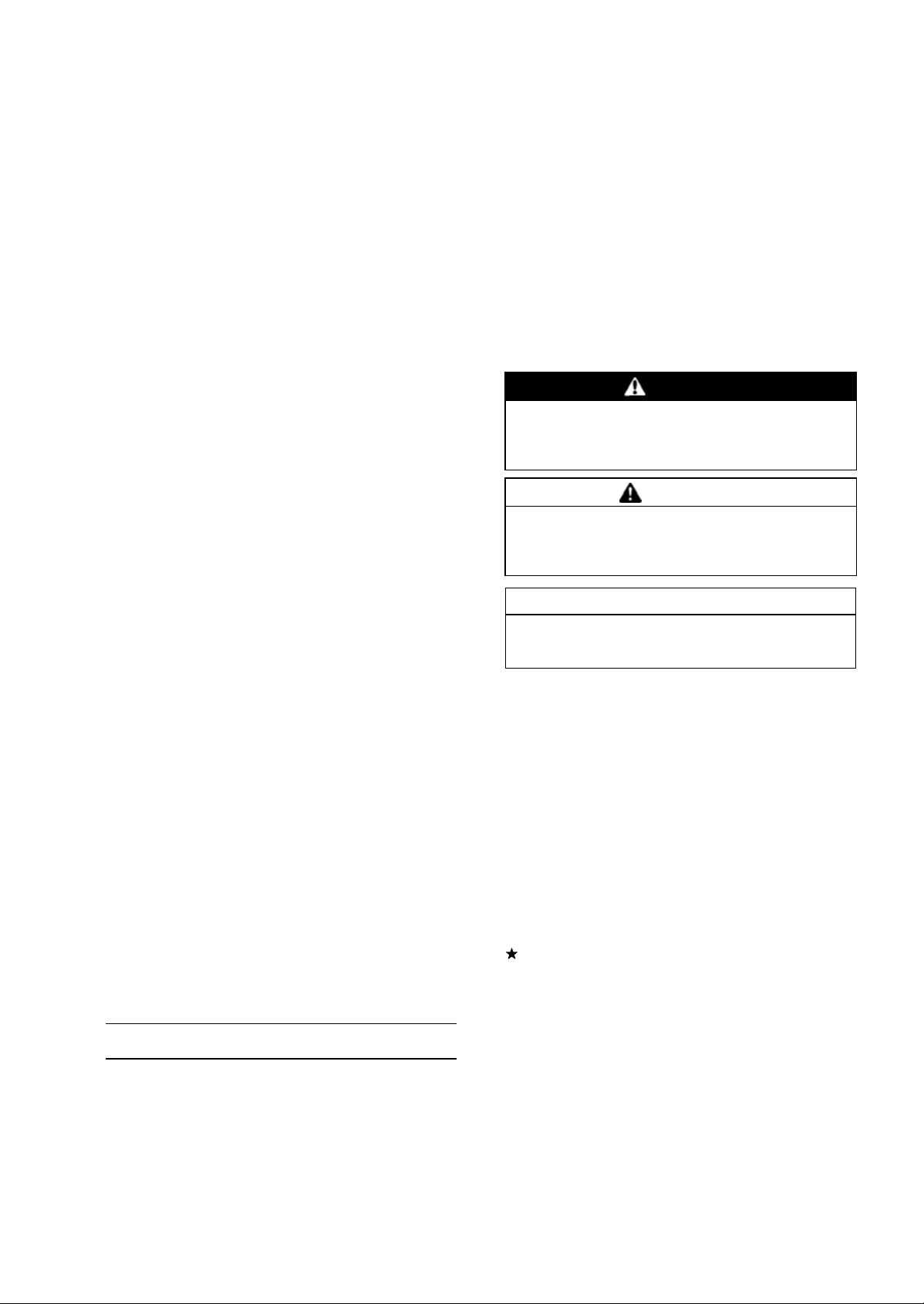
Arrangement and Cleaning of Removed Parts
Disassembled parts are easy to confuse. Arrange the
parts according to the order the parts were disassembled
and clean the parts in order prior to assembly.
Storage of Remov ed Parts
After all the parts including subassembly parts have been
cleaned, store the parts in a clean area. Put a clean cloth
or plastic sheet over the parts to protect from any foreign
materials that may collect before re-assembly.
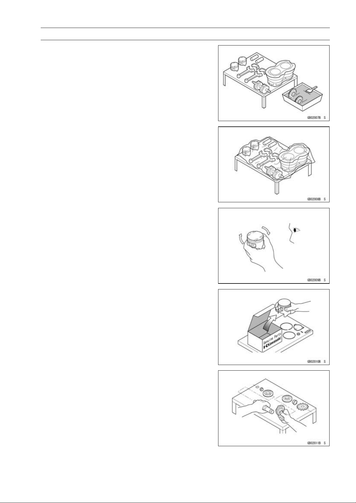
Inspection
Reuse of worn or damaged parts may lead to serious ac-
cident. Visually inspect removed parts for corrosion, discol-
oration, or other damage. Refer to the appropriate sections
of this manual for service limits on individual parts. Replace
the parts if any damage has been found or if the part is be-
yond its service limit.
Replacement Parts
Replacement parts must be KAWASAKI genuine or
recommended by KAWASAKI. Gaskets, O-rings, oil seals,
grease seals, circlips, cotter pins or self-locking nuts must
be replaced with new ones whenever disassembled.
Assembly Order
In most cases assembly order is the reverse of disassem-
bly, however, if assembly order is provided in this Service
Manual, follow the procedures given.
1-4 GENERAL INFORMATION
Before Servicing
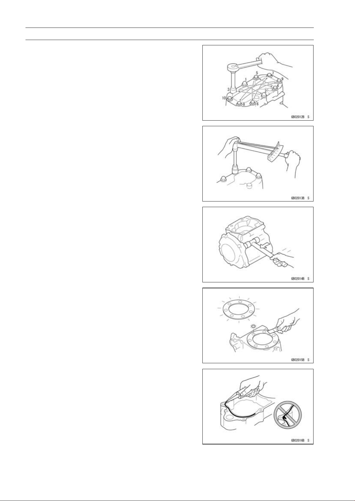
Tightening Sequence
Generally, when installing a part with several bolts, nuts,
or screws, start them all in their holes and tighten them to
a snug fit. Then tighten them according to the specified se-
quence to prevent case warpage or deformation which can
lead to malfunction. Conversely when loosening the bolts,
nuts, or screws, first loosen all of them by about a quar-
ter turn and then remove them. If the specified tightening
sequence is not indicated, tighten the fasteners alternating
diagonally.
Tightening Torque
Incorrect torque applied to a bolt, nut, or screw may
lead to serious damage. Tighten fasteners to the specified
torque using a good quality torque wrench.
All of the tightening torque values are for use with dry,
solvent - cleaned threads unless otherwise indicated. If a
fastener which should have dry, clean threads gets contami-
nated with lubricant, etc., applying even the specified torque
could damage it.
Force
Use common sense during disassembly and assembly,
excessive force can cause expensive or hard to repair dam-
age. When necessary, remove screws that have a non
-permanent locking agent applied using an impact driver.
Use a plastic-faced mallet whenever tapping is necessary.
Gasket, O-ring
Hardening, shrinkage, or damage of both gaskets and
O-rings after disassembly can reduce sealing performance.
Remove old gaskets and clean the sealing surfaces thor-
oughly so that no gasket material or other material remains.
Install the new gaskets and replace the used O-rings when
re-assembling.
Liquid Gasket, Non-permanent Locking Agent
For applications that require Liquid Gasket or a
Non-permanent Locking Agent, c lean the surfaces so
that no oil residue remains before applying liquid gasket or
non-permanent locking agent. Do not apply them exces-
sively. Excessive application can clog oil passages and
cause serious damage.
GENERAL INFORMATION 1-5
Before Servicing
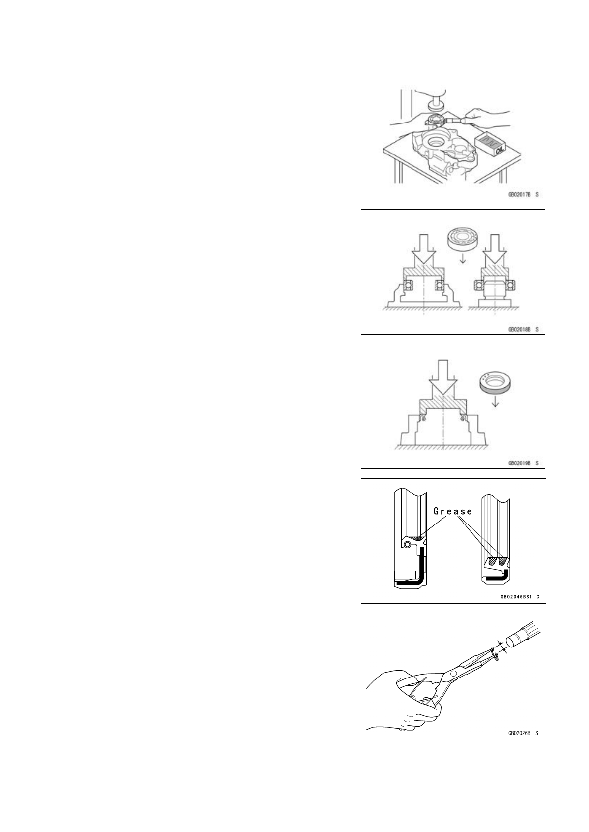
Press
For items such as bearings or oil seals that must be
pressed into place, apply small amount of oil to the con-
tact area. Be sure to maintain proper alignment and use
smooth movements when installing.
Ball Bearing and Needle Bearing
Do not remove pressed ball or needle unless removal is
absolutely necessary. Replace with new ones whenever
removed. Press bearings with the manufacturer and size
marks facing out. Press the bearing into place by putting
pressure on the correct bearing race as shown.
Pressing the incorrect race can cause pressure between
the i nner and outer race and result in bearing damage.
Oil Seal, Grease Seal
Do not remove pressed oil or grease seals unless removal
is necessary. Replace with new ones whenever removed.
Press new oil seals with manufacture and size marks facing
out. Make sure the seal is aligned properly when installing.
Apply specified grease to the lip of seal before installing
the seal.
Circlips, Cotter Pins
Replace the circlips or cotter pins that were removed with
new ones. Take care not to open the clip excessively when
installing to prevent deformation.
1-6 GENERAL INFORMATION
Before Servicing
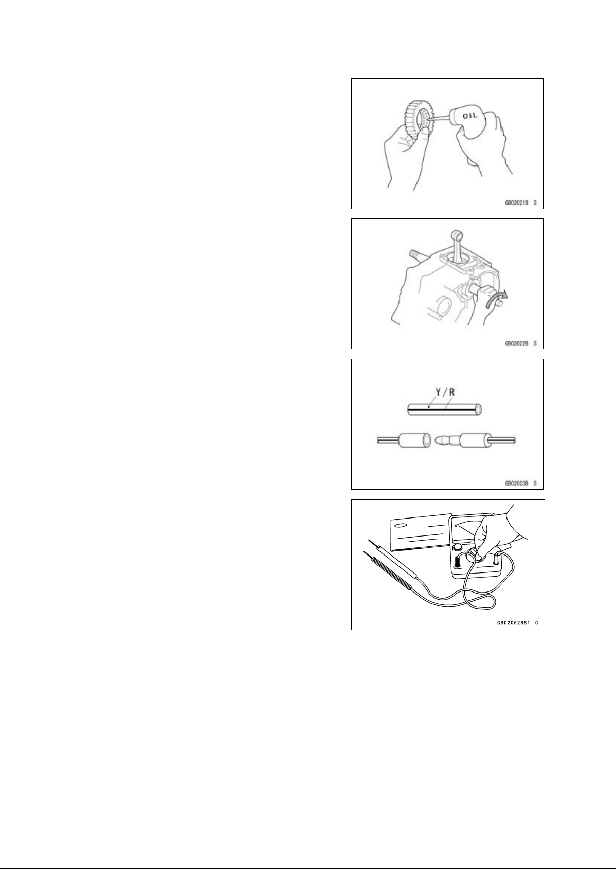
Lubrication
It is important to lubricate rotating or sliding parts during
assembly to minimize wear during initial operation. Lubri-
cation points are called out throughout this manual, apply
the specific oil or grease as specified.
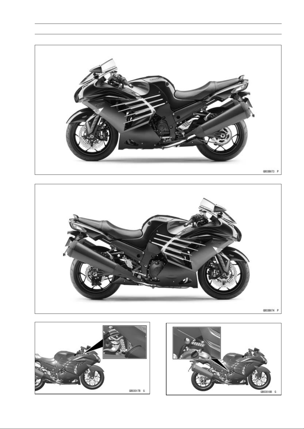
Direction of Engine Rotation
When rotating the crankshaft by hand, the free play
amount of rotating direction will affect the adjustment. Ro-
tate the crankshaft to positive direction (clockwise viewed
from output side).
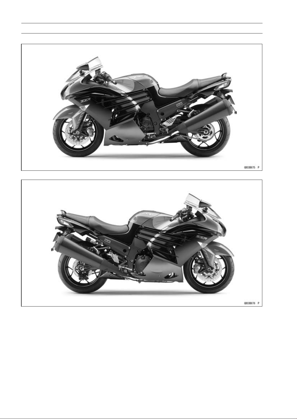
Electrical Wires
A two-color wire is identified first by the primary color and
then the stripe color. Unless instructed otherwise, electrical
wires must be connected to those of the same color.
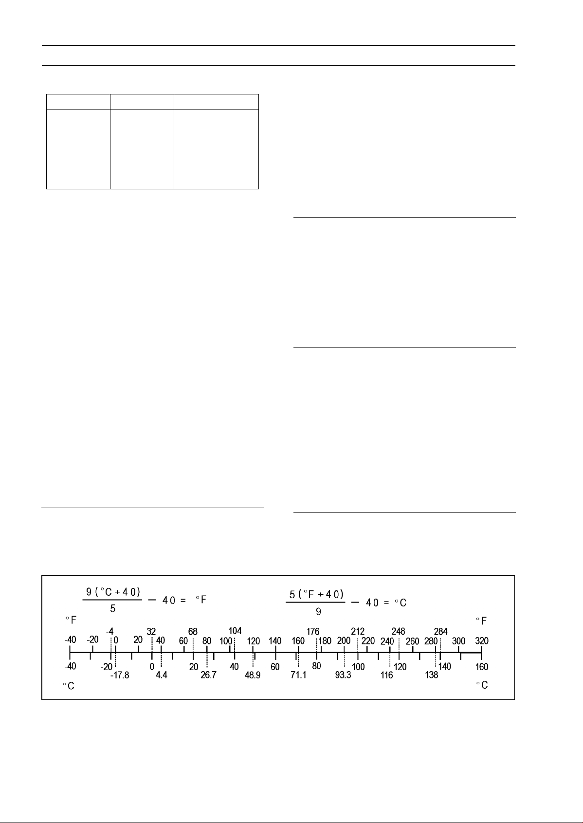
Instrument
Use a meter that has enough accuracy for an accurate
measurement. Read the manufacture’s instructions thor-
oughly before using the meter. Incorrect values may lead
to improper adjustments.
Handling Electronic Parts
Severe impacts to electronic parts such as the ECU, sen-
sor, and relay can damage them. If dropped on a hard sur-
face, replace such parts with new ones.
If a high voltage that is created by static electricity is ap-
plied to the electric parts, it could cause them to fail. To
avoid this, touch a non-painted metal surface to discharge
any static electricity that is accumulated on your body be-
fore inspecting or replacing electric parts.
Be careful not to touch the electrical terminals of the elec-
tronic parts. The static electricity discharged from your body
could damage them or deform the electrical terminals.
GENERAL INFORMATION 1-7
Model Identification
ZX1400HG Left Side View
ZX1400HG Right Side View
Frame Number Engine Number
1-8 GENERAL INFORMATION
Model Identification
ZX1400JG Left Side View
ZX1400JG Right Side View

GENERAL INFORMATION 1-9
General Specifications
Items ZX1400HG HK /JG JK
Dimensions
Overall Length 2 170 mm (85.43 in.)
Overall Width 770 mm (30.3 in.)
(ID, MY, PH, SEA-B1, TH) 780 mm (30.7 in.)
Overall Height 1 170 mm (46.06 in.)
Wheelbase 1 480 mm (58.27 in.)
Road Clearance 125 mm (4.92 in.)
Seat Height 800 mm (31.5 in.)
Curb Mass: 269 kg (593 lb)
Front 135 kg (298 lb)
Rear 134 kg (295 lb)
Fuel Tank Capacity 22 L (5.8 US gal.)
Performance
Minimum Turning Radius
3.1m(10.2ft)
Engine
Type
4-stroke, DOHC, 4-cylinder
Cooling System
Liquid-cooled
Bore and Stroke 84.0 × 65.0 mm (3.3 × 2.6 in.)
Displacement 1 441 cm³ (87.93 cu in.)
Compression Ratio 12.3:1
Maximum Horsepower 147.2 kW (200 PS) @10 000 r/min (rpm)
(ZX1400HG HH/JG JH AU) 147 kW (200 PS) @10 000 r/min
(rpm)
(CA, CAL, US) – – –
Maximum Torque
158.2 N·m (16.1 kgf·m, 117 ft·lb) @7 500 r/min (rpm)
(ZX1400HG HH/JG JH AU) 158 N·m (16.1 kgf·m, 117 ft·lb)
@7 500 r/min (rpm)
(CA, CAL, US) – – –
Fuel System FI (Fuel Injection), MIKUNI 44EIDW × 4
Fuel Type:
Minimum Octane Rating:
Research Octane
Number (RON)
95
Antiknock Index
(RON + MON)/2
90
Starting System Electric starter
Ignition System Battery and coil (transistorized)
Timing Advance Electronically advanced (IC igniter in ECU)
Ignition Timing 10° BTDC @1 100 r/min (rpm) to 40.1° BTDC @6 000 r/min (rpm)
Spark Plug NGK CR9EIA-9
Cylinder Numbering Method Left to right, 1-2-3-4
Firing Order 1-2-4-3

1-10 GENERAL INFORMATION
General Specifications
Items ZX1400HG HK/JG JK
Valve Timing:
Intake:
Open 34° BTDC
Close 72° ABDC
Duration 286°
Exhaust:
Open 66° BBDC
Close 36° ATDC
Duration 282°
Lubrication System Forced lubrication (wet sump)
Engine Oil:
Type
API SG, SH, SJ, SL or SM with JASO MA, MA1 or MA2
Viscosity SAE 10W-40
Capacity 4.6 L (4.9 US qt)
Drive Train
Primary Reduction System:
Type Gear
Reduction Ratio 1.556 (84/54)
Clutch Type
Wet multi disc
Transmission:
Type 6-speed, constant mesh, return shift
Gear Ratios:
1st 2.611 (47/18)
2nd 1.947 (37/19)
3rd 1.545 (34/22)
4th 1.333 (32/24)
5th 1.154 (30/26)
6th
1.036 (29/28)
Final Drive System:
Type Chain drive
Reduction Ratio 2.471 (42/17)
Overall Drive Ratio 3.980 @Top gear
Frame
Type Press backbone
Caster (Rake Angle) 23.0°
Trail 93 mm (3.7 in.)
Front Tire:
Type Tubeless
Size 120/70ZR17 M/C (58W)
Rim Size 17M/C × MT3.50
Rear Tire:
Type Tubeless
Size 190/50ZR17 M/C (73W)
Rim Size 17M/C × MT6.00

GENERAL INFORMATION 1-11
General Specifications
Items ZX1400HG HK /JG JK
Front Suspension:
Type Telescopic fork (upside-down)
Wheel Travel 117 mm (4.61 in.)
Rear Suspension:
Type
Swingarm (uni-trak)
Wheel Travel 124 mm (4.88 in.)
(Öhlins) 120 mm (4.72 in.)
Brake Type:
Front Dual discs
Rear Single disc
Electrical Equipment
Battery 12V12Ah(10HR)
Headlight:
Type Semi-sealed beam
High Beam 12 V (65 W + 55 W) × 2
Low Beam 12 V 55 W × 2
Brake/Tail Light LED
Alternator:
Type Three-phase AC
Maximum Output 14.0V–35.0A@5000r/min(rpm)
Specifications are subject to change without notice, and may not apply to every country.
1-12 GENERAL INFORMATION
Unit Conversion Table
Prefixes for Units:
Prefix Symbol Power
mega M × 1 000 000
kilo k × 1 000
centi c ×0.01
milli m × 0.001
micro × 0.000001
Units of Mass:
kg × 2.205 = lb
g × 0.03527 = oz
Units of Volume:
L × 0.2642 = gal (US)
L × 0.2200 = gal (IMP)
L×1.057=
qt (US)
L × 0.8799 =
qt (IMP)
L × 2.113 = pint (US)
L × 1.816 = pint (IMP)
mL × 0.03381 = oz (US)
mL × 0.02816 = oz (IMP)
mL × 0.06102 = cu in.
Units of Force:
N × 0.1020 = kg
N × 0.2248 = lb
kg × 9.807 = N
kg × 2.205 = lb
Units of Length:
km × 0.6214 = mile
m × 3.281 = ft
mm × 0.03937 = in.
Units of Torque:
N·m × 0.1020 = kgf·m
N·m × 0.7376 = ft·lb
N·m × 8.851 = in·lb
kgf·m × 9.807 = N·m
kgf·m × 7.233 = ft·lb
kgf·m × 86.80 = in·lb
Units of Pressure:
kPa × 0.01020 = kgf/cm²
kPa × 0.1450 = psi
kPa × 0.7501 = cmHg
kgf/cm² × 98.07 = kPa
kgf/cm² × 14.22 = psi
cmHg × 1.333 = kPa
Units of Speed:
km/h
× 0.6214 = mph
Units of Power:
kW × 1.360 = PS
kW × 1.341 = HP
PS
× 0.7355 = kW
PS × 0.9863 = HP
Units of Temperature:

PERIODIC MAINTENANCE 2-1
2
Periodic Maintenance
Table of Contents
Periodic Maintenance Chart ................................................................................................... 2-3
Torque and Locking Agent...................................................................................................... 2-5
Specifications ......................................................................................................................... 2-15
Special Tools and Sealant ...................................................................................................... 2-17
Periodic Maintenance Procedure ........................................................................................... 2-18
Fuel System (DFI)................................................................................................................ 2-18
Air Cleaner Element Replacement.................................................................................... 2-18
Idle Speed Inspection ....................................................................................................... 2-19
Idle Speed Adjustment...................................................................................................... 2-19
Throttle Control System Inspection................................................................................... 2-19
Engine Vacuum Synchronization Inspection..................................................................... 2-20
Fuel System Inspection..................................................................................................... 2-23
Fuel Filter Replacement.................................................................................................... 2-23
Fuel Hose Replacement ................................................................................................... 2-26
Evaporative Emission Control System Inspection (Other than US, CA, AU, ID, PH and
ZX1400JJ of SEA-B3 Models) ....................................................................................... 2-28
Cooling System.................................................................................................................... 2-29
Coolant Level Inspection................................................................................................... 2-29
Cooling System Inspection ............................................................................................... 2-29
Coolant Change ................................................................................................................ 2-29
Water Hose and O-ring Replacement ............................................................................... 2-32
Engine Top End ................................................................................................................... 2-32
Valve Clearance Inspection .............................................................................................. 2-32
Valve Clearance Adjustment............................................................................................. 2-34
Air Suction System Damage Inspection............................................................................ 2-36
Clutch................................................................................................................................... 2-36
Clutch System Inspection ................................................................................................. 2-36
Clutch Operation Inspection ............................................................................................. 2-37
Clutch Fluid Level Inspection............................................................................................ 2-37
Clutch Fluid Change ......................................................................................................... 2-38
Clutch Hose Replacement ................................................................................................ 2-39
Rubber Parts of Clutch Master Cylinder/Slave Cylinder Replacement............................. 2-40
Engine Lubrication...............................................................................................................2-41
Engine Oil Change............................................................................................................ 2-41
Oil Filter Replacement ...................................................................................................... 2-42
Wheels/Tires........................................................................................................................ 2-43
Air Pressure Inspection..................................................................................................... 2-43
Wheels and Tires .............................................................................................................. 2-43
Wheel Bearing Damage Inspection .................................................................................. 2-44
Final Drive............................................................................................................................ 2-45
Drive Chain Lubrication Condition Inspection ................................................................... 2-45
Drive Chain Slack Inspection............................................................................................ 2-45
Drive Chain Slack Adjustment .......................................................................................... 2-46
Wheel Alignment Inspection ............................................................................................. 2-47
Drive Chain Wear Inspection ............................................................................................ 2-47
Chain Guide Wear Inspection........................................................................................... 2-48
Brakes.................................................................................................................................. 2-49
Brake System Inspection .................................................................................................. 2-49
Brake Operation Inspection .............................................................................................. 2-50
Brake Fluid Level Inspection............................................................................................. 2-50

2-2 PERIODIC MAINTENANCE
Brake Fluid Change .......................................................................................................... 2-52
Brake Hose and Pipe Replacement.................................................................................. 2-54
Master Cylinder Rubber Parts Replacement .................................................................... 2-56
Caliper Rubber Parts Replacement .................................................................................. 2-58
Brake Pad Wear Inspection .............................................................................................. 2-62
Brake Light Switch Operation Inspection .......................................................................... 2-63
Suspension.......................................................................................................................... 2-63
Suspension System Inspection......................................................................................... 2-63
Steering ............................................................................................................................... 2-65
Steering Play Inspection ................................................................................................... 2-65
Steering Play Adjustment.................................................................................................. 2-65
Steering Stem Bearing Lubrication ................................................................................... 2-66
Electrical System ................................................................................................................. 2-67
Lights and Switches Operation Inspection........................................................................ 2-67
Headlight Aiming Inspection ............................................................................................. 2-69
Side Stand Switch Operation Inspection........................................................................... 2-71
Engine Stop Switch Operation Inspection......................................................................... 2-72
Spark Plug Replacement .................................................................................................. 2-72
Others.................................................................................................................................. 2-73
Chassis Parts Lubrication ................................................................................................ 2-73
Bolts, Nuts and Fasteners Tightness Inspection............................................................... 2-74
PERIODIC MAINTENANCE 2-3
Periodic Maintenance Chart
The scheduled maintenance must be done in accordance with this chart to keep the motorcycle in
good running condition.The initial maintenance is vitally important and must not be neglected.
Periodic Inspection
*A: Service at number of years shown or indicated odometer reading intervals, whichever comes
first.
*B: For higher odometer readings, repeat at the frequency interval established here.
*C: Service more frequently when operating in severe conditions: dusty, wet, muddy, high speed,
or frequent starting/stopping.
*D: Other than US, CA, AU, ID, PH and ZX1400JJ of SEA-B3 Models
: Emission Related Item
: Inspection
: Change or Replace
: Lubrication
Odometer Reading (*B)
× 1 000 km (× 1 000 mile)
Items
year
(*A)
1
(0.6)
6
(3.8)
12
(7.6)
18
(11.4)
24
(15.2)
See
Page
Fuel System
Air cleaner element (*C)
2-18
Idle speed 2-19
Throttle control system (play, smooth return,
no drag)
:1
2-19
Engine vacuum synchronization 2-20
Fuel system
:1
2-23
Fuel filter 2-23
Fuel hose
:5
2-26
Evaporative emission control system (*D) 2-28
Cooling System
Coolant level
2-29
Cooling system
:1
2-29
Coolant, water hose and O-ring
:3
: every 36 000 km
(22 500 mile)
2-29,
2-32
Engine Top End
Valve clearance (US and CA Models) 2-32
Valve clearance (Other than US and CA
Models)
: every 42 000 km
(26 250 mile)
2-32
Air suction system 2-36
Clutch
Clutch operation (play, engagement,
disengagement)
2-37
Clutch fluid level
:1
2-37
Clutch fluid, hose and pipe
:1
2-36
Clutch fluid
:2
2-38
2-4 PERIODIC MAINTENANCE
Periodic Maintenance Chart
Odometer Reading (*B)
× 1 000 km (× 1 000 mile)
Items
year
(*A)
1
(0.6)
6
(3.8)
12
(7.6)
18
(11.4)
24
(15.2)
See
Page
Clutch hose/rubber parts of clutch master
cylinder and slave cylinder
:4
: every 48 000 km
(30 000 mile)
2-39,
2-40
Engine Lubrication System
Engine oil and oil filter
(*C)
:1
2-41,
2-42
Wheels and Tires
Tire air pressure
:1
2-43
Wheel and tire
:1
2-43
Wheel bearing damage
:1
2-44
Final Drive
Drive chain lubricatio
n condition (*C)
: every 600 km (400 mile)
2-45
Drivechainslack(*C)
: every 1 000 km (600 mile)
2-45
Drive chain wear (*C)
2-47
Drive chain guide wear 2-48
Brakes
Brake system
:1
2-49
Brake operation (effectiveness, play, no
drag)
:1
2-50
Brake fluid level
:1
2-50
Brake fluid (front and rear)
:2
2-52
Brake hose
:4
2-54
Rubber parts of brake master cylinder and
caliper
:4
: every 48 000 km
(30 000 mile)
2-56,
2-58
Brake pad wear (*C)
2-62
Brake light switch operation 2-63
Suspension
Suspension system
:1
2-63
Steering
Steering play
:1
2-65
Steering stem bearing
:2
2-66
Electrical System
Electrical system
:1
2-67
Spark plug 2-72
Others
Chassis parts
:1
2-73
Condition of bolts, nuts and fasteners 2-74
PERIODIC MAINTENANCE 2-5
Torque and Locking Agent
The following tables list the tightening torque for the major fasteners requiring use of a
non-permanent locking agent or silicone sealant etc. All of the values are for use with dry solvent -
cleaned threads unless otherwise indicated.
Letters used in the “Remarks” column mean:
AL: Tighten the two clamp bolts alternately two times to ensure even tightening torque.
G: Apply grease.
L: Apply a non-permanent locking agent.
LG: Apply liquid gasket.
MO: Apply molybdenum disulfide oil solution.
(mixture of the engine oil and molybdenum disulfide grease in a weight ratio 10:1)
R: Replacement Parts
S: Follow the specified tightening sequence.
Si: Apply silicone grease.
Torque
Fastener
N·m kgf·m ft·lb
Remarks
Fuel System (DFI)
Front Air Intake Duct Mounting Bolts 8.0 0.82 71 in·lb
Idle Speed Control Valve Actuator Bracket Bolts
8.0 0.82 71 in·lb
Idle Speed Control Valve Actuator Mounting Bolts 6.0 0.61 53 in·lb
Intake Air Temperature Sensor Screw 0.50 0.05 4.4 in·lb
Air Cleaner Cap Bolts 8.0 0.82 71 in·lb
Rear Air Intake Duct Mounting Bolts 10 1.0 89 in·lb L
Air Intake Duct Clamp Bolts
7.0 0.71 62 in·lb
Air Cleaner Element Cover Bolts
8.0 0.82 71 in·lb
Duct Clamp Bolts 2.0 0.20 18 in·lb
DrainHoseFitting 20 2.0 15 L
Breather Pipe Bolt 8.0 0.82 71 in·lb L
Throttle Case Cover Screws (ZX1400H Model) 3.5 0.36 31 in·lb
Throttle Case Cover Screws (ZX1400J Model) 3.0 0.31 27 in·lb
Delivery Pipe M ounting Screws 5.0 0.51 44 in·lb
Throttle Cable Holder Screw 4.0 0.41 35 in·lb
Throttle Body Assy Holder Bolts 10 1.0 89 in·lb S
Throttle Body Assy Holder Clamp Bolts 2.0 0.20 18 in·lb
Vehicle-down Sensor Bracket Bolt
8.0 0.82 71 in·lb
Vehicle-down Sensor Mounting Bolts
6.0 0.61 53 in·lb
Spark Plugs
13 1.3 115 in·lb
Water Temperature Sensor 12 1.2 106 in·lb
Gear Position Sensor Bolt 10 1.0 89 in·lb L
Gear Position Sensor Holder Bolts (L = 20 mm) 5.0 0.51 44 in·lb L
Crankshaft Sensor Bolts 6.0 0.61 53 in·lb L
Oxygen Sensor 25 2.5 18
Fuel Tank Bolts 8.0 0.82 71 in·lb
Fuel Tank Cap Bolts 4.5 0.46 40 in·lb
Fuel Level Sensor Bolts 7.0 0.71 62 in·lb L
Bracket Bolts 8.0 0.82 71 in·lb
Fuel Pump Assembly Screws
0.98 0.10 8.7 in·lb R

2-6 PERIODIC MAINTENANCE
Torque and Locking Agent
Torque
Fastener
N·m kgf·m ft·lb
Remarks
Fuel Pump Bolts 10 1.0 89 in·lb L, S
Canister Bracket Screws
1.2 0.12 11 in·lb
Hose Bracket Bolt 8.0 0.82 71 in·lb
Purge Valve Bracket Bol
t
8.0 0.82 71 in·lb
Purge Valve Mounting Nut 8.0 0.82 71 in·lb
Cooling System
Radiator Upper Bolts 20 2.0 15
Water Hose Clamp Screws 3.0 0.31 27 in·lb
Coolant Fitting Bolts 9.0 0.92 80 in·lb L
Thermostat Housing Mo
unting Bolts
10 1.0 89 in·lb
Radiator Stay Bolt 8.0 0.82 71 in·lb
Radiator Lower Bolt 8.0 0.82 71 in·lb
Thermostat Housing Cover Bolts 6.0 0.61 53 in·lb
Cylinder Fitting Mounting Bolts
10 1.0 89 in·lb
Oil Cooler Mounting Bolts
12 1.2 106 in·lb
L, S
Water Pump Mounting Bolts 12 1.2 106 in·lb
Coolant Reserve Tank Cap – – – Hand-tighten
Water Pump Cover Bolts 12 1.2 106 in·lb
Coolant Drain Bolt 10 1.0 89 in·lb
Coolant Reserve Tank Bolts
8.0 0.82 71 in·lb L
Engine Top End
Air Suction Valve Cover Bolts 10 1.0 89 in·lb L
Cylinder Head Cover Bolts 10 1.0 89 in·lb S
Camshaft Sprocket Mounting Bolts 15 1.5 11 L
Throttle Body Assy
Holder Bolts
10 1.0 89 in·lb S
Throttle Body Assy Holder Clamp Bolts
2.0 0.20 18 in·lb
Camshaft Cap Bolts
12 1.2 106 in·lb
S
Water Passage Plugs 20 2.0 15 L
Front Camshaft Chain Guide Bolt (Upper) 25 2.5 18
Cylinder Head Bolts (M6) 12 1.2 106 in·lb S
Cylinder Head Bolts (M11)
see the
text
– – MO, S
Camshaft Chain Tensioner Mounting Bolts 10 1.0 89 in·lb
Front Camshaft Chain Guide Bolt (Lower) 12 1.2 106 in·lb
Engine Bracket Bolts 25 2.5 18
R, S
Front Engine Mounting Bolts 60 6.1 44
R, S
Muffler Cover
Bolts
10 1.0 89 in·lb
Muffler Guard Bolts 8.0 0.82 71 in·lb
Muffler Body Mounting Bolts 34 3.5 25
Muffler Body Cover Bolts 8.0 0.82 71 in·lb L
Exhaust Pipe Manifold Holder Nuts 17 1.7 13 S
Muffler Body Clamp Bolts 17 1.7 13
PERIODIC MAINTENANCE 2-7
Torque and Locking Agent
Torque
Fastener
N·m kgf·m ft·lb
Remarks
Clutch
Clutch Reservoir Cap Stopper Screw (ZX1400H
Model)
2.0 0.20 18 in·lb
Clutch Reservoir Cap Stopper Screw (ZX1400J
Model)
1.2 0.12 11 in·lb
Clutch Reservoir Bracket Bolt 9.0 0.92 80 in·lb
Clutch Cover Bolts 10 1.0 89 in·lb L(1),S
Oil Filler Plug – – – Hand-tighten
Clutch Hose Banjo Bolts 25 2.5 18
Clutch Reservoir Bolt 8.0 0.82 71 in·lb
Clutch Lever Pivot Bolt 1.0 0.10 8.9 in·lb Si
Clutch Master Cylinder Bleed Valve 8.0 0.82 71 in·lb
Clutch Lever Pivot Bolt Locknut
5.9 0.60 52 in·lb
Starter Lockout Switch Screw
0.70 0.07 6.2 in·lb L
Clutch Master Cylinder Clamp Bolts
10.3 1.05 91 in·lb
S
Clutch Hose Clamp Bolts 8.0 0.82 71 in·lb
Clutch Spring Bolts 11 1.1 97 in·lb
Sub Clutch Hub Bolts 25 2.5 18 L
Clutch Hub Nut 135 13.8 100 R
Clutch Slave Cylinder Bleed Valve 8.5 0.87 75 in·lb
Clutch Slave Cylinder Bolts 8.0 0.82 71 in·lb L
Engine Lubrication System
Oil Pipe Mounting Bolts 10 1.0 89 in lb L
Oil Pipe Bolts 10 1.0 89 in lb L
Oil Passage Plug (R1/4)
15 1.5 11 L
Oil Cooler Mounting Bolts
12 1.2 106 inlb
L, S
Oil Pump Cover Bolts
10 1.0 89 in lb
Oil Pan Plate Bolts 10 1.0 89 in lb L
Oil Filter 17 1.7 13 G, R
Oil Filter Holder Mounting Bolt 35 3.6 26 L
Oil Pressure Relief Valve 15 1.5 11 L
Oil Pan Bolts 10 1.0 89 in lb
Oil Pressure Switch Terminal Bolt 2.0 0.20 18 in lb G
Oil Pressure Switch 15 1.5 11 LG
Engine Oil Drain Bolt 29 3.0 21
Oil Passage Plug (R3/8) 20 2.0 15 L
Engine Removal/Installation
Engine Bracket Bolts 25 2.5 18
R, S
Front Engine Mounting Bolts 60 6.1 44
R, S
Adjusting Collars 15 1.5 11 M, S
Engine Mounting Nuts 60 6.1 44 R, S
Crankshaft/Transmission
Breather Cover Bolts (L = 25 mm) 10 1.0 89 in·lb L
2-8 PERIODIC MAINTENANCE
Torque and Locking Agent
Torque
Fastener
N·m kgf·m ft·lb
Remarks
Breather Cover Bolt (L = 35 mm) 10 1.0 89 in·lb
Breather Cover Plate Screws
10 1.0 89 in·lb L
Connecting Rod Big End Nuts
see the
text
MO, R
Oil Nozzle Pipe Mounting Bolts
25 2.5 18
Oil Passage Plugs (R3/8)
20 2.0 15 L
Bearing Position Pla
te Screws
10 1.0 89 in·lb L
Shift Drum Bearing Holder Screws 10 1.0 89 in·lb L
Drive Shaft Cover Bolts 25 2.5 18 L
Crankcase Bolts (M7, L = 60 mm) 20 2.0 15 S
Crankcase Bolt (M7, L = 110 mm) 20 2.0 15 S
Crankcase Bolts (M7, L = 45 mm) 20 2.0 15 S
Crankcase Bolts (M10, L = 90 mm) 49 5.0 36 MO, S
Crankcase Bolt (M7, L = 85 mm) 20 2.0 15 S
Crankcase Bolt (M7, L = 50 mm) 20 2.0 15 S
Crankcase Bolts (M10, L = 120 mm) 49 5.0 36 MO, S
Crankcase Bolts (M7, L = 65 mm)
20 2.0 15
S
Crankcase Bolts (M6, L = 40 mm)
12 1.2 106 in·lb
S
Crankcase Bolts
(M8, L = 70 mm)
27 2.8 20
S
Crankcase Bolt (M6, L = 50 mm) 12 1.2 106 in·lb S
Crankcase Bolts (M6, L = 25 mm) 12 1.2 106 in·lb S
Crankcase Bolts (M8, L = 80 mm) 27 2.8 20 S
Crankcase Bolt (M6, L = 65 mm) 12 1.2 106 in·lb S
Balancer Shaft Clamp Bolts 10 1.0 89 in·lb
Balancer Shaft Clamp Lever Bolts 25 2.5 18
Starter Clutch Shaft Bolt 10 1.0 89 in·lb L
Starter Clutch Shaft Plate Bolt 10 1.0 89 in·lb L
Shift Shaft Return Spring Pin 29 3.0 21 L
Torque Limiter Bolt 25 2.5 18 L
Gear Positioning Lever Bolt 12 1.2 106 in·lb
Shift Drum Cam Holder Bolt 12 1.2 106 in·lb L
Gear Position Sensor Holder Bolt (L = 14 mm) 6.0 0.61 53 in·lb L
Shift Pedal Bolt 8.0 0.82 71 in·lb
Gear Position Sensor Holder Bolts (L = 20 mm) 5.0 0.51 44 in·lb L
Wheels/Tires
Front Axle Clamp Bolts
20 2.0 15 AL
Front Axle Nut 130 13.3 95.9
Rear Axle Nut 130 13.3 95.9
Final Drive
Engine Sprocket Cover Bolts 10 1.0 89 in·lb L(1)
Plate Mounting Bolts 10 1.0 89 in·lb L
Chain Guide Bolts (M6) 10 1.0 89 in·lb L
Chain Guide Bolt (M8) 12 1.2 106 in·lb L
Loading...