


AUDIO/VIDEO CONTROL RECEIVER
RX-DP20VSL
|
|
DVD |
AUDIO |
LEARN |
TRANSMIT |
|
|
|
|
TV/DBS |
VCR 1 |
|
|
LEARN |
|
DVD |
DVD MULTI |
PHONO |
CD |
VCR 1 |
VCR 2 |
TAPE/MD |
CDR |
TV/DBS |
VIDEO |
FM/AM |
EXT 7.1CH |
ANALOG/DIGITAL |
|
EFFECT |
|
|
|
|
|
|
INPUT |
|
|
3 |
|
|
|
|
|
SOUND |
|
|
|
|
|
|
|
|
|
|
|
6 |
|
|
|
|
|
TEST |
|
|
|
|
|
|
|
|
|
|
|
9 |
|
|
|
|
|
CC |
|
|
|
|
|
|
MASTER |
VOLUME |
|
|
+10 |
|
|
|
|
|
|
|
|
|
100+ |
|
|
|
|
|
THX |
SURROUND |
DSP |
SURR/DSP |
STANDBY |
CC CONVERTER |
DIM MER |
|
|
|
|
|
OFF |
|
|
|
EX/ES/7.1 |
|
DIRECT |
|||
STANDBY/ ON |
|
|
|
|
|
|
|
TV |
|
DOOR |
|
|
|
|
|
CATV/ |
|
|
|
|
|
|
|
|
DBS |
|
|
|
UP |
|
|
|
|
|
|
|
RX-DP20V |
|
|
|
REW |
PLAY |
|
|
|
|
|
|
( |
PTY SEARCH |
|
||
|
|
DOOR |
|
|
|
STOP |
|
PAUSE |
|
|
DOWN |
|
|
|
|
|
|
|
|
|
|
|
|
DISPLAY MODE |
TA/NEWS/INFO |
|
|
|
|
|
|
|
TV/VIDEO |
|
|
|
|
|
|
|
CHANNEL |
|
VOLUME |
|
|
|
|
|
|
|
MUTING |
|
|
|
AUDIO/VIDEO |
RECEIVER |
|
|
|
|
|
|
|
|
|
|
|
SETUP |
|
|
ADJUST |
|
|
|
|
|
MENU |
|
|
MENU |
|
|
|
|
|
TEXT |
SET |
|
|
|
|
|
|
|
DISPLAY |
|
|
|
|
|
|
|
|
DVD |
|
|
EXIT |
|
|
|
|
|
MENU |
|
|
|
PHONES |
|
|
|
|
|
|
|
|
|
|
DIGITAL |
S-VIDEO |
VIDEO |
L—AUDIO—R |
|
|
|
|
|
|
|
VIDEO |
|
|
|
|
|
|
|
|
|
RM- |
|
CONTROL |
|
|
|
|
|
|
|
A/V |
|
|
|
|
|
|
INSTRUCTIONS |
|
|
|
|
|
|
|
|
|
|
|
|
|
|
|
|
|
|
|
|
|
|
|
|
|
|
|
|
|
|
|
|
|
|
|
|
|
|
|
|
Enter below the Model No. and Serial |
||
|
|
|
|
|
For Customer Use: |
||
|
|
|
|
|
|
No. which are located either on the rear, |
|
|
|
|
|
|
|
bottom or side of the cabinet. Retain this |
|
|
|
|
|
|
|
information for future reference. |
|
|
|
|
|
|
|
Model No. |
|
|
|
|
|
|
|
|
|
|
|
|
|
|
|
Serial No. |
|
|
|
|
|
|
|
|
|
|
|
|
|
|
|
|
|
LVT0965-003A
[B]
Warnings, Cautions and Others
IMPORTANT for the U.K.
DO NOT cut off the mains plug from this equipment. If the plug fitted is not suitable for the power points in your home or the cable is too short to reach a power point, then obtain an appropriate safety approved extension lead or consult your dealer.
BE SURE to replace the fuse only with an identical approved type, as originally fitted.
If nonetheless the mains plug is cut off ensure to remove the fuse and dispose of the plug immediately, to avoid a possible shock hazard by inadvertent connection to the mains supply.
If this product is not supplied fitted with a mains plug then follow the instructions given below:
IMPORTANT.
DO NOT make any connection to the terminal which is marked with the letter E or by the safety earth symbol or coloured green or green-and-yellow.
The wires in the mains lead on this product are coloured in accordance with the following code:
Blue : Neutral Brown : Live
As these colours may not correspond with the coloured markings identifying the terminals in your plug proceed as follows:
The wire which is coloured blue must be connected to the terminal which is marked with the letter N or coloured black.
The wire which is coloured brown must be connected to the terminal which is marked with the letter L or coloured red.
IF IN DOUBT - CONSULT A COMPETENT ELECTRICIAN.
CAUTION
To reduce the risk of electrical shocks, fire, etc.:
1.Do not remove screws, covers or cabinet.
2.Do not expose this appliance to rain or moisture.
Caution ––  (STANDBY/ON) switch!
Disconnect the mains plug to shut the power off completely. The  (STANDBY/ON) switch in any position does not disconnect the mains line. The power can be remote controlled.
CAUTION
•Do not block the ventilation openings or holes.
(If the ventilation openings or holes are blocked by a newspaper or cloth, etc., the heat may not be able to get out.)
•Do not place any naked flame sources, such as lighted candles, on the apparatus.
•When discarding batteries, environmental problems must be considered and local rules or laws governing the disposal of these batteries must be followed strictly.
•Do not use this apparatus in a bathroom or places with water.
Also do not place any containers filled with water or liquids (such as cosmetics or medicines, flower vases, potted plants, cups, etc.) on top of this apparatus.
CAUTION!
To avoid personal injury or accidentally dropping the unit, have two persons unpack, carry, and install the unit.
24 kg
G-1
SAFETY INSTRUCTIONS
“SOME DOS AND DON’TS ON THE SAFE USE OF EQUIPMENT”
This equipment has been designed and manufactured to meet international safety standards but, like any electrical equipment, care must be taken if you are to obtain the best results and safety is to be assured.
Do read the operating instructions before you attempt to use the equipment.
Do ensure that all electrical connections (including the mains plug, extension leads and interconnections between pieces of equipment) are properly made and in accordance with the manufacturer’s instructions. Switch off and withdraw the mains plug when making or changing connections.
Do consult your dealer if you are ever in doubt about the installation, operation or safety of your equipment.
Do be careful with glass panels or doors on equipment.
DON’T continue to operate the equipment if you are in any doubt about it working normally, or if it is damaged in any way–switch off, withdraw the mains plug and consult your dealer.
DON’T remove any fixed cover as this may expose dangerous voltages.
DON’T leave equipment switched on when it is unattended unless it is specifically stated that it is designed for unattended operation or has a standby mode.
Switch off using the switch on the equipment and make sure that your family know how to do this.
Special arrangements may need to be made for infirm or handicapped people.
DON’T use equipment such as personal stereos or radios so that you are distracted from the requirements of traffic safety. It is illegal to watch television whilst driving.
DON’T listen to headphones at high volume as such use can permanently damage your hearing.
DON’T obstruct the ventilation of the equipment, for example with curtains or soft furnishings.
Overheating will cause damage and shorten the life of the equipment.
DON’T use makeshift stands and NEVER fix legs with wood screws — to ensure complete safety always fit the manufacturer’s approved stand or legs with the fixings provided according to the instructions.
DON’T allow electrical equipment to be exposed to rain or moisture.
ABOVE ALL
—NEVER let anyone, especially children, push anything into holes, slots or any other opening in the case -this could result in a fatal electrical shock.;
—NEVER guess or take chances with electrical equipment of any kind — it is better to be safe than sorry!
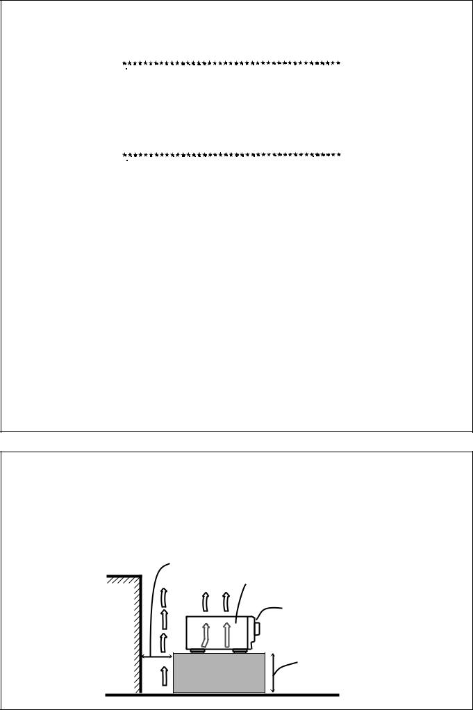
Caution: Proper Ventilation
To avoid risk of electric shock and fire and to protect from damage.
Locate the apparatus as follows:
Front: |
No obstructions open spacing. |
Sides: |
No obstructions in 10 cm from the sides. |
Top: |
No obstructions in 10 cm from the top. |
Back: |
No obstructions in 15 cm from the back |
Bottom: |
No obstructions, place on the level surface. |
In addition, maintain the best possible air circulation as illustrated.
Spacing 15 cm or more
RX-DP20VSL
Front
Wall or obstructions
Stand height 15 cm or more
Floor
G-2


 Introduction
We would like to thank you for purchasing one of our JVC products.
Before operating this unit, read this manual carefully and thoroughly to obtain the best possible performance from your unit, and retain this manual for future reference.
Features
THX Ultra2 certified
The newly introduced THX Ultra2 standard ensures the highest sound and picture quality and the most reliable performance by using seven-channel amplification to reproduce multi-channel software. In newly developed THX Ultra2 Cinema Mode and THX Music Mode, all multi-channel software (5.1 channels or more) is automatically detected and proper processing is applied to improve directional and ambient surround information through four surround speakers—two at the side and two at the back.
Compatible with various audio formats including DTS 96/24
RX-DP20VSL allows you to enjoy newly introduced audio formats such as Dolby Digital EX, Dolby Pro Logic II, DTS-ES, DTS NEO:6, and DTS 96/24.
•This unit is also compatible with Dual Mono signals recorded in Dolby Digital and DTS discs.
7.1 channel DAP (Digital Acoustic Processor)
Sound field simulation technology allows precise ambience recreation of existing theaters and halls. Thanks to the highperformance DSP (Digital Signal Processor) and high-capacity memory, you can enjoy 7.1-channel surround by playing 2- channel or multi-channel software.
Multi-channel headphone virtual surround sound—3D HEADPHONE
The built-in headphone virtual surround system is compatible with multi-channel software. You can enjoy a natural surround sound through the headphones.
192 kHz/24 bit PEM DD audio DA converter
The JVC-exclusive converter is now upgraded to be fully compatible with DVD Audio’s high specifications. Subtle nuances are accurately reproduced.
K2 Technology
K2 technology has been designed to enable natural audio reproduction, achieving a drastic reduction in digital distortion and creating original sound ambience with high precision.
CC(Compensative Compression) Converter
CC Converter eliminates jitter and ripples, achieving a drastic reduction in digital distortion by processing the digital music data in 24 bit–quantization and by expanding the sampling frequency to 128 kHz (for fs 32 kHz signals)/176.4 kHz (for fs 44.1 kHz signals)/192 kHz (for fs 48 kHz signals). By using the CC Converter, you can obtain a natural sound field from any source.
ZIST (Zero Interference audio Signal Transmission) circuit
The ZIST circuit incorporated for the EXT 7.1 CH IN (input) jacks successfully eliminates the video signal interference to the audio signals by making the cold side of the audio signals completely independent from the ground.
COMPU LINK remote control system
The COMPU LINK remote control system allows you to operate other JVC audio/video components from this receiver.
TEXT COMPU LINK remote control system
The TEXT COMPU LINK remote control system has been developed to deal with the disc information recorded on the CD Text and MDs. Using this information on the discs, you can operate the CD player or MD recorder through the receiver.
Precautions
Power sources
•When unplugging the receiver from the wall outlet, always pull the plug, not the AC power cord.
•Do not handle the AC power cord with wet hands.
•If you are not going to operate the receiver for an extended period of time, unplug the AC power cord from the wall outlet.
Ventilation
The seven high power amplifiers built in this receiver will generate heat inside the cabinet.
For safety, observe the following carefully:
•Make sure there is good ventilation around the receiver. Poor ventilation could overheat and damage the receiver.
•Do not block the ventilation openings or holes. (If the ventilation openings or holes are blocked by a newspaper or cloth, etc., the heat may not be able to get out.)
Others
•Should any metallic object or liquid fall onto the unit, unplug the unit and consult your dealer before operating any further.
•Do not use this receiver in a bathroom or places with water.
•Do not place any containers filled with water or liquids (such as cosmetics or medicines, flower vases, potted plants, cups, etc.) on top of this receiver.
•Do not disassemble the unit since there are no user serviceable parts inside.
If anything goes wrong, unplug the AC power cord and consult your JVC dealer.
1

Table of Contents |
|
Parts Identification ...................................... |
3 |
Getting Started ........................................... |
7 |
Before Installation ...................................................................... |
7 |
Checking the Supplied Accessories ........................................... |
7 |
Connecting the FM and AM (MW/LW) Antennas ..................... |
7 |
Connecting the Speakers ............................................................ |
8 |
Connecting Audio/Video Components ..................................... |
11 |
7 Analog Connections ............................................................. |
11 |
7 Digital Connections .............................................................. |
16 |
Connecting the Power Cord ..................................................... |
17 |
Putting Batteries in the Remote Control .................................. |
17 |
Basic Operations ....................................... |
18 |
Simple Operating Procedure .................................................... |
18 |
Turning the Power On and Off (Standby) ................................ |
19 |
Selecting the Source to Play ..................................................... |
19 |
Adjusting the Volume ............................................................... |
21 |
Activating the Front Speakers .................................................. |
21 |
Selecting the Analog or Digital Input Mode ............................ |
21 |
Attenuating the Input Signal .................................................... |
22 |
Muting the Sound ..................................................................... |
23 |
Turning Analog Direct On and Off .......................................... |
23 |
Making Sounds Natural ............................................................ |
23 |
Changing the Display Brightness ............................................. |
23 |
Changing the Source Name ...................................................... |
23 |
Using the Sleep Timer .............................................................. |
24 |
Receiving Radio Broadcasts ........................ |
25 |
Tuning in to Stations Manually ................................................ |
25 |
Using Preset Tuning ................................................................. |
25 |
Selecting the FM Reception Mode ........................................... |
26 |
Receiving FM Stations with RDS ............................................ |
26 |
Searching for a Program by PTY Codes .................................. |
27 |
Switching to a Program of Your Choice Automatically ........... |
28 |
Basic Settings ........................................... |
29 |
Setup Menu Configuration ....................................................... |
29 |
Operation through On-Screen Display Menus ......................... |
30 |
Menu Operating Procedure ...................................................... |
31 |
1 Setting the Speakers—SPEAKER SETTING ..................... |
32 |
2 Adjusting the Speaker Channel Output Levels |
|
—CHANNEL LEVEL ........................................................ |
32 |
3 Setting the Speaker Distance—SPEAKER DISTANCE ... |
34 |
4 Setting the Bass Sounds—SUBWOOFER .......................... |
34 |
5 Setting the THX Audio—THX AUDIO SETUP ................... |
35 |
6 Setting the Surround Channel Output Speakers |
|
—SURR CH OUT ............................................................... |
36 |
7 Setting the Audio Delay Level—AUDIO DELAY................ |
36 |
8 Selecting the Dual Mono Sound—DUAL MONO ............... |
36 |
9 Setting the Digital Input/Output Terminals |
|
—DIGITAL IN/OUT .......................................................... |
36 |
p Setting the Video Input Terminals—VIDEO INPUT .......... |
37 |
q Turning On and Off the Video Output—VIDEO POWER ........ |
37 |
w Setting the Speakers 2 Usage—SPEAKER 2 .................... |
37 |
e Superimposing the Menus—SUPERIMPOSE .................... |
38 |
r Showing the Text Information on the Display |
|
—FL DISPLAY ................................................................... |
38 |
t Memorizing the Volume Level for Each Source |
|
—ONE TOUCH OPE ......................................................... |
38 |
Sound Adjustments.................................... |
39 |
Adjustment Menu Configuration ............................................. |
39 |
Operation through On-Screen Display Menus ......................... |
40 |
Menu Operating Procedure ...................................................... |
41 |
1 Adjusting the Parametric Equalizer for Each Channel |
|
—PEQ FRONT/CENTER/SURROUND/SURR BACK .......... |
42 |
2 Setting the Midnight Mode—MIDNIGHT MODE ............ |
43 |
3 Adjusting the Various Effects—EFFECT ADJUST ............ |
43 |
Using the Surround and THX Modes ................... |
45 |
Reproducing Theater Ambience ............................................... |
45 |
Introducing the Surround and THX Modes .............................. |
45 |
Surround and THX Modes Applicable to the Various Software ..... |
47 |
Activating the Surround and THX Modes ............................... |
49 |
7 Activating the 7.1-channel reproduction ............................. |
49 |
7 Activating the Surround Modes ........................................... |
50 |
7 Activating the THX Modes .................................................. |
51 |
Using the DSP Modes ....................................... |
52 |
Reproducing the Sound Field ................................................... |
52 |
Introducing the DSP Modes ..................................................... |
52 |
Activating the DSP Modes ....................................................... |
53 |
Using the Analog Multi-channel Playback Mode ..... |
54 |
Activating the Analog Multi-channel Playback Modes .............. |
54 |
COMPU LINK Remote Control System ......... |
55 |
TEXT COMPU LINK Remote Control System ..... |
56 |
7 Showing the Disc Information on the TV Screen ................. |
57 |
7 Searching for a Disc (Only for the CD player) ..................... |
58 |
7 Entering the Disc Information .............................................. |
59 |
Operating JVC’s Audio/Video Components ... |
61 |
Operating Audio Components .................................................. |
61 |
Operating Video Components .................................................. |
63 |
Operating Other Manufacturers’ Equipment... |
64 |
Changing the Preset Signal Codes ........................................... |
64 |
Storing the Remote Signals Manually ...................................... |
68 |
Troubleshooting ......................................... |
71 |
Additional Information ................................ |
72 |
Specifications............................................ |
73 |
2

 Parts Identification
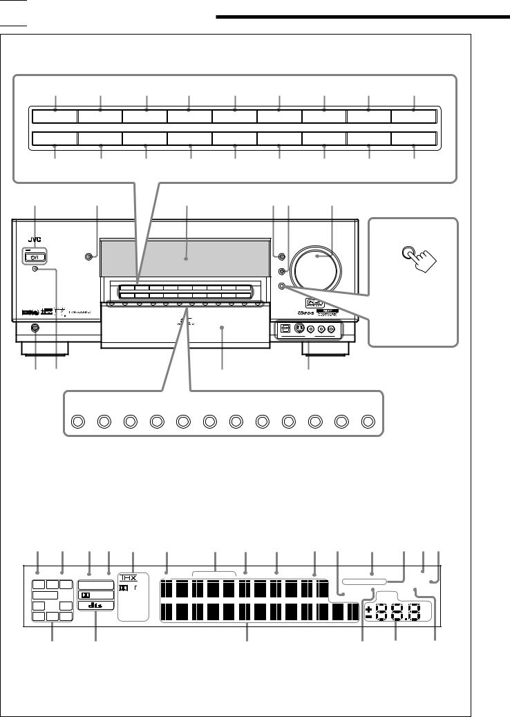
Front Panel
|
1 |
2 |
|
3 |
|
|
4 |
|
|
5 |
|
6 |
7 |
|
8 |
9 |
|
SPEAKERS 1 |
INPUT MODE |
|
THX |
|
|
SURROUND |
|
SURR/DSP |
ADJUST MENU |
DOWN |
|
UP |
SET |
||||
|
|
|
|
OFF |
/ TUNING ∞ |
/ TUNING 5 |
/ MEMORY |
||||||||||
|
|
|
|
|
|
|
|
|
|
|
|
||||||
SPEAKERS 2 |
INPUT ATT |
EX/ES/7.1 |
|
DSP |
|
ANALOG |
SETUP MENU |
LEFT |
|
RIGHT |
EXIT |
||||||
|
|
DIRECT |
/ PRESET ∞ |
/ PRESET 5 |
/ FM MODE |
||||||||||||
|
|
|
|
|
|
|
|
|
|
|
|
||||||
|
p |
q |
|
w |
|
|
e |
|
r |
|
t |
y |
|
u |
i |
||
|
|
|
|
|
|
|
|
|
|
|
|
|
|
|
|
g |
|
|
|
|
|
|
|
|
|
|
|
|
|
|
|
|
|
|
DOOR |
|
|
|
|
|
|
|
|
|
|
|
|
|
|
|
|
|
DOWN |
|
|
|
SPEAKERS 1 |
INPUT MODE |
THX |
SURROUND |
SURR/DSP |
ADJUST MENU |
DOWN |
UP |
SET |
|
|
|
|
To open the front door, |
|
|
|
|
|
|
|
|
OFF |
|
/ TUNING ∞ |
/ TUNING 5 |
/ MEMORY |
|
|
|
|
||
|
|
|
SPEAKERS 2 |
INPUT ATT |
EX/ES/7.1 |
DSP |
ANALOG |
SETUP MENU |
LEFT |
RIGHT |
EXIT |
|
|
|
|
||
|
|
|
DIRECT |
/ PRESET ∞ |
/ PRESET 5 |
/ FM MODE |
|
|
|
|
press DOOR DOWN. |
||||||
|
|
|
|
|
|
|
|
|
|
|
|
|
|
|
|
||
|
|
|
|
|
|
|
|
|
|
|
|
|
|
|
|
(For more details, see |
|
|
|
|
|
|
|
|
|
|
|
|
|
|
|
|
|
page 18.) |
|
|
PHONES |
|
|
|
|
|
|
|
|
|
|
|
|
|
|
|
|
h |
j |
|
|
|
|
|
|
|
|
|
|
|
|
/ |
|
|
|
|
k |
|
|
|
|
|
|
|
|
|
|
|
|
|
|
|
|
|
DVD |
DVD MULTI |
VCR 1 |
VCR 2 |
TV/DBS |
VIDEO |
|
CD |
PHONO |
TAPE/MD |
CDR |
FM/AM |
EXT 7.1CH |
|
|||
Display Window
1 2 3 4 5 6 |
|
7 8 9 0 - = ~ ! @ |
||||||||||
DUAL |
ANALOG |
DGTL AUTO 96/24 |
RDS |
TA |
NEWS INFO TUNED |
STEREO |
AUTO MUTING |
ONE TOUCH OPERATION |
SLEEP |
|||
L |
C |
R |
LINEAR PCM |
PL |
|
|
|
|
SPEAKERS |
1 2 |
|
BI-AMP |
|
|
|
|
PARAMETRIC EQ |
MIDNIGHT MODE |
|||||||
|
|
|
|
|
|
|
|
|||||
SUBWFR |
LFE |
DIGITAL |
Neo:6 |
|
|
|
|
INPUT ATT |
VOLUME |
|
||
LS |
S |
RS |
|
DSP |
|
|
|
|
|
|
|
|
|
3D-PHONIC |
|
|
|
|
|
|
|
|
|||
|
|
|
|
|
|
|
|
|
|
|
|
|
|
SB |
|
|
HEADPHONE |
|
|
|
|
|
|
|
dB |
# |
$ |
% |
^ & |
* |
3

Refer to the pages in parentheses for details.
Front Panel
1 SPEAKERS 1 button (18, 21)
2 INPUT MODE button (22)
3 THX button (51, 54)
4 SURROUND button (50, 51)
5 SURR/DSP OFF button (50, 51, 53, 54)
6 ADJUST MENU button (40)
7DOWN button (30, 40) TUNING ∞ button (25)
8UP button (30, 40) TUNING 5 button (25)
9SET button (30, 40) MEMORY button (25)
p SPEAKERS 2 button (18, 21) q INPUT ATT button (22)
w EX/ES/7.1 button (49) e DSP button (53)
r ANALOG DIRECT button (23) t SETUP MENU button (30)
yLEFT button (30, 40) PRESET ∞ button (25)
uRIGHT button (30, 40) PRESET 5 button (25)
iEXIT button (30, 40) FM MODE button (26)
o (STANDBY/ON) button and STANDBY lamp (18, 19)
•STANDBY lamp lights up in red when the unit is turned off.
; CC CONVERTER button and lamp (23)
•CC CONVERTER lamp lights up in blue when CC Converter is turned on.
a Display
s DIMMER button (23) d DOOR UP button (18)
f MASTER VOLUME control (18, 21) g DOOR DOWN button (18)
h PHONES jack (21) j Remote sensor
kSource selecting buttons (18–21)
•DVD, DVD MULTI, VCR 1, VCR 2, TV/DBS, VIDEO, CD, PHONO, TAPE/MD, CDR, FM/AM, EXT 7.1CH
l Front door
/ VIDEO input terminals (12)
Display Window
1DUAL indicator (20)
•Lights up when Dual Mono signals are detected.
2 ANALOG indicator (22)
•Lights up when an analog input (source) is selected.
3 DGTL AUTO indicator (22)
•Lights up when auto digital input (DIGITAL AUTO) is selected.
496/24 indicator (46)
•Lights up when DTS 96/24 signals are detected.
5 Surround/THX/DSP mode indicators
•Indicate the current Surround/THX/DSP mode setting.
6 RDS indicator (26)
7 Program type (TA/NEWS/INFO) indicators (28)
8 TUNED indicator (25)
•Lights up when a station is received.
9STEREO indicator (25)
•Lights up when an FM stereo station is received.
0 AUTO MUTING indicator (26)
•Lights up when the FM station reception mode is set to Auto Reception mode (AUTO MUTING).
-INPUT ATT indicator (22)
•Lights up when Input Attenuator is in use.
= ONE TOUCH OPERATION indicator (38)
•Lights up when One Touch Operation is in use.
~ SPEAKERS 1/2 indicators (21)
•Lights up to indicate the activated front speakers.
! SLEEP indicator (24)
•Lights up when Sleep Timer is in use.
@BI-AMP indicator (37)
•Lights up when “SPEAKER 2” is set to “BI-AMP OUT.”
# Speaker and signal indicators (20)
•Speaker indicators : Indicate the activated speakers.
• Signal indicators : Indicate the incoming channel signals.
$Digital signal format indicators (22)
•Indicates the digital signal format of incoming signals.
% Main display
•Shows the source name, station frequency, Surround/THX/ DSP mode, etc.
^PARAMETRIC EQ indicator (42)
•Lights up when Parametric Equalizer is in use.
& VOLUME level indicator
•Indicates the volume level.
•Goes off while muting sounds.
*MIDNIGHT MODE indicator (43)
• Lights up when Midnight Mode is in use.
4
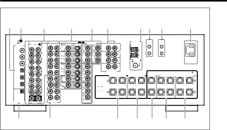
Rear Panel
1 |
2 |
3 |
4 |
5 |
6 |
7 |
8 |
9 |
p |
|
RIGHT |
LEFT |
AUDIO |
|
DIGITAL IN |
MM |
MC |
RIGHT |
LEFT |
|
|
|
TV SOUND |
|
|
|
|
|
|
|
|
|
|
DBS |
1 (DVD) |
IN |
|
PHONO |
IN |
|
|
|
||
|
|
|
|
OUT |
|
IN |
|
CD |
(REC) |
2 (CD) |
|
VCR 1 |
||
|
|
|
||
|
|
|
|
IN |
|
OUT |
|
|
(PLAY) |
3 (TV |
(REC) |
|
TAPE |
|
/DBS) |
|
|
MD |
OUT |
|
|
|
||
|
IN |
|
|
(REC) |
|
|
|
VCR 2 |
|
|
(PLAY) |
|
|
|
4 (CDR) |
|
|
|
IN |
|
OUT |
|
|
(PLAY) |
|
(REC) |
|
CDR |
|
|
|
|
DVD |
|
|
IN |
|
FRONT |
|
5 (MD) |
|
IN |
||
|
(PLAY) |
|
|
|
|
|
|
SUB |
MONITOR |
6 (VCR 1) |
FRONT |
|
WOOFER |
OUT |
|
|
CENTER |
||
|
|
|
SURR |
|
PCM |
SUB |
|
|
|
/ DOLBY DIGITAL |
WOOFER |
|
CENTER |
|
/ DTS |
SURR |
|
SURR |
|
(REAR) |
BACK |
|
DIGITAL OUT |
R |
DVD IN |
L |
R |
L |
|
PREOUT |
||||
|
|
|
|
|
VIDEO |
COMPONENT |
AUDIO |
|
ANTENNA |
VIDEO |
S-VIDEO |
RIGHT |
LEFT |
AM |
|
|
EXT |
||||
|
Y |
Y |
FRONT |
|
|
|
|
|
|
||
|
|
|
|
CENTER |
AM |
|
PB |
PB |
|
|
LOOP |
|
SUB |
|
|
||
|
1 IN |
2 |
|
|
|
|
WOOFER |
|
|
||
|
(DVD) |
IN |
|
|
|
|
|
|
|
PR |
PR |
|
|
|
|
FM 75 |
|
|
SURR |
|
|
|
COAXIAL |
Y |
|
|
|
|
|
|
|
|
SURR |
|
|
|
|
|
|
BACK |
R |
L |
|
|
PB |
|
|
EXT 7.1CH IN |
|
|
|
|
|
|
|
|
|
|
3 IN |
|
|
FRONT 1 SPEAKERS |
FRONT 2 SPEAKERS |
||
PR |
CAUTION : |
|
|
|
|
|
SPEAKER |
+ |
|
|
|
||
|
|
|
|
|||
|
IMPEDANCE |
|
|
|
||
|
|
|
|
|
||
Y |
FRONT 1 AND 2: |
|
|
|
|
|
|
8 |
16 |
|
|
|
|
PB |
FRONT 1 OR 2: |
|
|
|
|
|
4 |
16 |
– |
|
|
|
|
|
|
|
|
|||
PR |
|
|
RIGHT |
LEFT |
RIGHT |
LEFT |
|
|
|
|
|
|
|
MONITOR OUT |
|
|
|
|
|
|
COMPU |
LINK-4 |
(SYNCHRO) |
CENTER SPEAKER
TEXT |
COMPU |
LINK |
 AC IN
AC IN
CAUTION : SPEAKER IMPEDANCE 8 16
SURROUND |
|
SURROUND BACK |
SPEAKERS |
|
SPEAKERS |
+
–
RIGHT |
LEFT |
RIGHT |
LEFT |
q |
w |
e |
r t y |
u |
1DIGITAL IN terminals (16)
•Coaxial: 1 (DVD), 2 (CD), 3 (TV/DBS)
•Optical: 4 (CDR), 5 (MD), 6 (VCR 1)
2 Earth (ground) terminal (11)
3 Audio input/output jacks (13–15)
• Input: PHONO IN, CD IN, TAPE/MD IN, CDR IN
TV SOUND/DBS IN, VCR 1 IN, VCR 2 IN, DVD IN (5.1 ch)
• Output: TAPE/MD OUT, CDR OUT VCR 1 OUT, VCR 2 OUT
4S-video/composite video input/output jacks (13–15)
•Input: TV SOUND/DBS IN, VCR 1 IN, VCR 2 IN, DVD IN
•Output: VCR 1 OUT, VCR 2 OUT, MONITOR OUT
5 Component video input/output jacks (13–15)
• Input: |
1 IN (DVD), 2 IN, 3 IN |
• Output: |
MONITOR OUT |
6 EXT 7.1CH IN (audio input) jacks (12)
7 FM/AM ANTENNA terminals (7, 8)
8 COMPU LINK-4 (SYNCHRO) terminals (55, 56)
9 TEXT COMPU LINK terminals (56) p  AC IN socket (17)
q DIGITAL OUT terminal (16)
wPREOUT jacks (10)
•FRONT, SUBWOOFER, CENTER, SURR, SURR BACK e FRONT 1 SPEAKERS terminals (9)
r FRONT 2 SPEAKERS terminals (9) t CENTER SPEAKER terminals (9)
y SURROUND SPEAKERS terminals (9)
u SURROUND BACK SPEAKERS terminals (9)
5
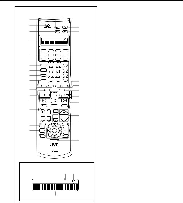
Remote Control
1 |
|
|
|
|
|
2 |
|
|
DVD |
AUDIO |
i |
|
LEARN |
TRANSMIT |
|
|
|
3 |
|
|
TV/DBS |
VCR 1 |
o |
|
|
|
|
||
4 |
|
|
LEARN |
|
|
|
|
|
|
|
|
|
DVD |
DVD MULTI |
PHONO |
CD |
|
5 |
VCR 1 |
VCR 2 |
TAPE/MD |
CDR |
|
|
TV/DBS |
VIDEO |
FM/AM |
EXT 7.1CH |
|
6 |
ANALOG/DIGITAL |
2 |
EFFECT |
|
|
INPUT |
1 |
3 |
|
||
7 |
SOUND |
|
|
LIVENESS |
|
|
4 |
5 |
6 |
; |
|
8 |
TEST |
|
|
|
|
|
7/P |
8 |
9 |
|
|
|
CC CONVERTER |
|
|
|
|
9 |
|
10 |
0 |
+10 |
a |
|
RETURN |
FM MODE |
100+ |
||
p |
THX |
SURROUND |
DSP |
SURR / DSP |
s |
q |
|
|
|
OFF |
|
EX / ES / 7.1 |
ANALOG DIRECT |
d |
|||
w |
SLEEP |
DIMMER TV |
f |
||
|
|
|
DBS |
||
|
|
|
|
CATV/ |
|
e |
/ REW |
PLAY |
|
FF/ |
g |
|
PTY( |
PTY SEARCH |
PTY9 |
||
|
REC |
STOP |
|
PAUSE |
|
r |
|
DISPLAY MODE TA/NEWS/INFO |
|
||
|
|
|
|
|
|
|
|
TV/VIDEO |
|
h |
|
|
TV VOL CHANNEL |
|
VOLUME |
||
|
|
MUTING |
|
|
|
t |
|
|
|
|
j |
SETUP |
|
|
ADJUST |
|
|
MENU |
|
|
MENU |
|
|
y |
TEXT |
SET |
|
|
|
DISPLAY |
|
|
|
||
|
|
|
|
||
u |
DVD |
|
|
EXIT |
|
MENU |
|
|
|
||
|
|
|
|
||
LIGHT |
k |
RM-SRXDP20R REMOTE CONTROL
A/V CONTROL RECEIVER
Remote’s display window
1 2
LEARN
3
1 DVD  button (63, 66, 69, 70) 2 LEARN/TRANSMIT selector
3 TV/DBS button (63–65, 69, 70)
4 Display window
5Source selecting buttons (18–21, 61–66, 68–70)
•DVD, DVD MULTI, PHONO, CD, VCR 1, VCR 2, TAPE/MD, CDR, TV/DBS, VIDEO, FM/AM, EXT 7.1CH
6 ANALOG/DIGITAL INPUT button (22, 61)
7 SOUND button (33, 44, 50, 53, 61)
8 TEST button (33, 61)
9 CC CONVERTER button (23, 61) p THX button (51, 54, 61)
q SURROUND button (50, 51, 61) w EX/ES/7.1 button (49, 61)
e SLEEP button (24)
r• Operating buttons for audio/video components (61–66, 69, 70)
•RDS operation buttons (26–28)
tOn-screen operation buttons (30, 40, 57)
• SETUP MENU, ADJUST MENU, SET, EXIT, % (UP), fi (DOWN), @ (LEFT), # (RIGHT)
y TEXT DISPLAY button (57) u DVD MENU button (63, 66) i AUDIO button (18, 19, 66)
o VCR 1  button (63, 65, 69, 70)
;• 10 keys for selecting preset channels (26, 61)
•10 keys for adjusting sound (33, 50, 61)
•10 keys for adjusting DSP effects (44, 53, 61)
•10 keys for operating audio/video components (61–70) a SURR/DSP OFF button (50, 51, 53, 54, 61)
s DSP button (53, 61)
d ANALOG DIRECT button (23, 61)
f TV operation mode selector (63–65, 69) g DIMMER button (23)
h VOLUME +/– buttons (18, 21) j MUTING button (23)
k LIGHT button (17)
Remote’s display window
1LEARN indicator
•Lights up when the LEARN/TRANSMIT selector is set to “LEARN.” This remote control cannot operate the receiver or other components, but can memorize remote control signals. (See page 68.)
2Signal transmission indicator
•Lights up when transmitting the remote control signals.
3 Remote control operation mode display
•Remote control operation mode such as “DVD,” “CD,” “SOUND,” etc. appears.
When the remote control operation mode changes, it is shown on this display for about 10 seconds.
(When showing the remote control operation mode just for confirmation, it is shown only for about 5 seconds—e.g. when pressing Number button 1 while the remote control operation mode is “CD,” “CD” appears for about 5 seconds.)
6

 Getting Started
This section explains how to connect audio/video components and speakers to the receiver, and how to connect the power supply.
Before Installation
General
•Be sure your hands are dry.
•Turn the power off on all components.
•Read the manuals supplied with the components you are going to connect.
Location
•Install the receiver in a location that is level, well-ventilated and free from moisture.
•The temperature around the receiver must be between –5˚C and 35˚C.
•Make sure there is good ventilation around the receiver. Poor ventilation could overheat and damage the receiver.
Handling the receiver
•Do not insert any metal object into the receiver.
•Do not disassemble the receiver or remove screws, covers, or cabinet.
•Do not expose the receiver to rain or moisture.
Checking the Supplied Accessories
Check to be sure you have all of the following items, which are supplied for the receiver.
The number in parentheses indicates the quantity of each piece supplied.
•Remote Control (1)
•Batteries (2)
•AM (MW/LW) Loop Antenna (1)
•FM Antenna (1)
•Front Terminal Cover (1)
•AC Power Cord (1)
If any item is missing, contact your dealer immediately.
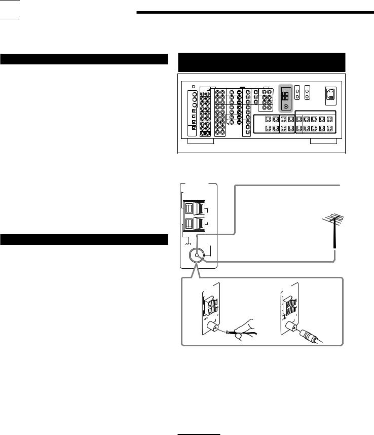
Connecting the FM and AM (MW/LW)
Antennas
Rear view
FM Antenna Connections
ANTENNA
AM
EXT
AM
LOOP
FM 75
COAXIAL
Extend the supplied FM antenna horizontally.
FM Antenna (supplied)
Outdoor FM Antenna Cable (not supplied)
A |
ANTENNA |
B |
ANTENNA |
|
AM |
AM |
|
|
EXT |
|
EXT |
|
75 |
|
75 |
|
FM |
|
FM |
|
COAXIAL |
|
COAXIAL |
A.Using the Supplied FM Antenna
The FM antenna provided can be connected to the FM 75Ω COAXIAL terminal as a temporary measure.
B.Using the Standard Type Connector with an Outdoor FM Antenna (not supplied)
A standard type connector (IEC or DIN45325) should be connected to the FM 75Ω COAXIAL terminal.
Note:
If reception is poor, connect an outdoor antenna.
Before attaching a 75Ω coaxial cable (the kind with a round wire going to an outdoor antenna), disconnect the supplied FM antenna.
7
AM (MW/LW) Antenna Connections
1 |
2 |
3 |
AM
LOOP
Turn the loop until you the best reception.
FM 75
COAXIAL
AM (MW/LW) Loop
Antenna (supplied)
Snap the tabs on the loop into the slots of the base to assemble the AM (MW/LW) loop.
Outdoor single vinyl-covered wire (not supplied)
Notes:
• If the AM (MW/LW) loop antenna wire is covered with vinyl, remove the vinyl by twisting it as shown in the diagram.
•Make sure the antenna conductors do not touch any
other terminals, connecting cords and power cord. This could cause poor reception.
•If reception is poor, connect an outdoor single vinyl-covered wire to the AM EXT terminal. Keep the AM (MW/LW) loop antenna connected.
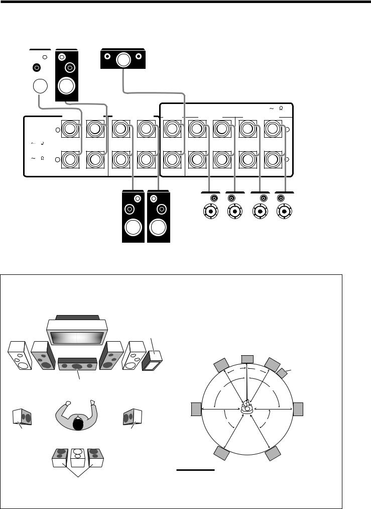
Connecting the Speakers
For full enjoyment of the THX modes (see page 45), it is recommended to use THX-certified speakers.
You can connect the following speakers:
•Two pairs of front speakers to produce normal stereo sound.
•One pair of surround speakers to produce a three-dimensional sound movement and environmental background-effect sounds.
•One or one pair of surround back speakers to enjoy 6.1-channel or 7.1-channel sound reproduction. A pair of the speakers is required to use THX Ultra2 Cinema and THX Music modes.
•One center speaker to produce a rich sound image by stabilizing the sound localization (also used to emphasize human voices).
•One powered subwoofer to enhance the bass and to reproduce the LFE channel recorded in multi-channel software.
For each speaker (except for a subwoofer), connect the (+) and (–) terminals on the rear panel to the (+) and (–) terminals marked on the speakers. For connecting a subwoofer, see page 10.
CAUTIONS:
Use only the speakers of the SPEAKER IMPEDANCE indicated by the speaker terminals.
•When connecting to both of the FRONT 1 and FRONT 2
SPEAKERS terminals, use speakers with an impedance of 8 Ω to 16 Ω.
•When connecting to either the FRONT 1 or FRONT 2
SPEAKERS terminals, use speakers with an impedance of 4 Ω to 16 Ω.
Rear view
Basic connecting procedure
1 |
2 |
3 |
4 |
1Cut, twist, and remove the insulation at the end of each speaker signal cable (not supplied).
2Turn the knob counterclockwise.
3Insert the speaker signal cable.
4Turn the knob clockwise.
Continued on the next page.
8
|
|
|
IMPORTANT: |
|
|
|
After connecting the speakers, set the speaker setting |
Front speakers 1 |
|
information properly: |
|
Right / Left |
Center speaker |
• To obtain the best possible Surround/THX/DSP effect, see “Basic |
|
|
|
|
Settings” on pages 29 to 38. |
|
|
|
• To connect the speakers to the FRONT 2 SPEAKERS terminal, |
|
|
|
set the speaker terminal usage correctly. (See “w Setting the |
|
|
|
Speakers 2 Usage—SPEAKER 2” on page 37.) |
|
|
|
|
|
|
|
|
|
|
|
|
|
|
CENTER |
CAUTION : SPEAKER IMPEDANCE 8 |
16 |
||
|
|
|
|
|
|
SURROUND |
SURROUND BACK |
|||
|
|
FRONT 1 SPEAKERS |
FRONT 2 SPEAKERS |
SPEAKER |
||||||
CAUTION : |
SPEAKERS |
SPEAKERS |
||||||||
|
|
|
|
|
|
|
|
|
||
SPEAKER |
+ |
|
|
|
|
|
|
|
+ |
|
IMPEDANCE |
|
|
|
|
|
|
|
|||
FRONT 1 AND 2: |
|
|
|
|
|
|
|
|
||
8 |
16 |
|
|
|
|
|
|
|
|
|
FRONT 1 OR 2 |
|
|
|
|
|
|
|
|
|
|
4 |
16 |
– |
|
|
|
|
|
|
|
– |
|
|
RIGHT |
LEFT |
RIGHT |
LEFT |
|
RIGHT |
LEFT |
RIGHT |
LEFT |
|
|
|
|
|
|
|
|
|
Right / Left |
Right / Left |
|||||
Surround speakers |
Surround back |
||||||
|
speakers* |
|
Right / Left |
* When using only one surround back speaker, |
|
Front speakers 2 |
||
connect it to the LEFT terminals. |
||
|
Speaker layout
Ideal speaker layout varies depending on the conditions of your listening room. The diagram below is a recommended typical example.
Subwoofer
Left front speaker(s) |
Right front speaker(s) |
||
(L) |
Center speaker |
(R) |
|
|
|
(C) |
|
Left surround |
Right surround |
speaker (LS) |
speaker (RS) |
Surround back speakers (LSB/RSB)
Front speakers and center speaker
•Place these speakers (position of the mid-range speaker units) at the same height from the floor.
•Place these speakers aiming at the listener’s ears.
Surround and surround back speakers
•Place these speakers at a position which is 1 meter higher than the listener’s ears.
•Point these speakers down aiming at the listener’s ears.
L |
C |
R |
|
||
30˚ |
30˚ |
Subwoofer |
90˚ |
|
90˚ |
LS |
|
RS |
60˚ |
|
60˚ |
LSB |
RSB |
Note:
Ideal speaker layout requires that all speakers be placed at the same distance from the listener. However, since in some places it may be difficult to fulfil this requirement, this unit can adjust the delay time so that the sounds through all the speakers reach the listener with the same timing. (See page 34.)
9
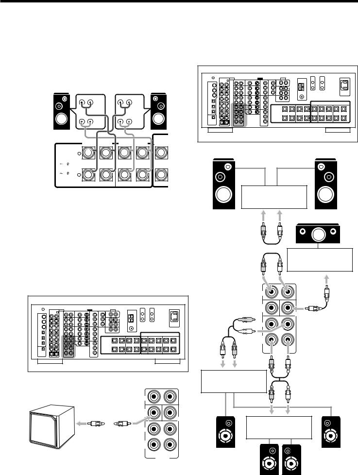
About the FRONT 2 SPEAKERS terminals
The FRONT 2 SPEAKERS terminals can be used as follows:
•To connect another pair of the front speakers.
•To connect only one pairs of the speakers and to drive them using two amplifiers built in this receiver.
If the speakers connected are of the bi-wiring connection type, you can connect the speakers as illustrated below. (You can use either front speaker terminals for high frequency or for low frequency terminals.)
Left Front speaker |
Rear view |
|
Right Front speaker |
||
|
|
|
|
|
|
|
|
|
HIGH |
|
HIGH |
|
|
|
LOW |
|
LOW |
|
|
|
|
|
CENTER |
CAUTION : |
FRONT 1 SPEAKERS |
FRONT 2 SPEAKERS SPEAKER |
|||
|
|
|
|
||
SPEAKER |
+ |
|
|
|
|
IMPEDANCE |
|
|
|
||
FRONT 1 AND 2: |
|
|
|
||
8 |
16 |
|
|
|
|
FRONT 1 OR 2: |
|
|
|
|
|
4 |
16 |
– |
|
|
|
|
|
RIGHT |
LEFT |
RIGHT |
LEFT |
To use the speaker with the above connection, see “w Setting the Speakers 2 Usage—SPEAKER 2” on page 37.
•When this connection is used, you cannot use the surround back speakers. (In this case, no sounds come out of the SURR BACK PREOUT jacks.)
Connecting a subwoofer
You can enhance the bass by connecting a subwoofer. Connect the input jack of a powered subwoofer to the
SUBWOOFER PREOUT jack on the rear panel, using a cable with RCA pin plugs (not supplied).
Rear view
Enhance your audio system
You can use this receiver as the pre-amplifier (control amplifier) when you connect power amplifiers to the PREOUT jacks on the rear panel, using cables with RCA pin plugs (not supplied).
•Connect the white plug to the audio left jack, and the red plug to the audio right jack.
Rear view
Left front speaker |
Right front speaker |
Power amplifier
Center speaker
R L
Power amplifier
R L
FRONT
SUB
WOOFER
CENTER


 R
R 


 L
L 

SURR
BACK
L |
R |
PREOUT |
R L
Power amplifier
|
FRONT |
|
|
SUB |
|
|
|
CENTER |
|
SURR |
|
|
SURR |
|
|
BACK |
|
Powered |
R |
L |
|
PREOUT |
|
|
|
subwoofer
R L
Power amplifier
Left surround |
Right surround |
speaker |
speaker |
Left |
/ Right |
surround back speakers
10
Connecting Audio/Video Components
When connecting individual components, refer also to the manuals supplied with them.

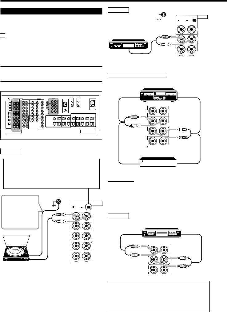
 Analog Connections
Audio component connections
Use the cables with RCA pin plugs (not supplied).
•Connect the white plug to the audio left jack, and the red plug to the audio right jack.
CAUTION:
If you connect a sound-enhancing device such as a graphic equalizer between the source components and this receiver, the sound output through this receiver may be distorted.
Rear view
Turntable
Set the MM/MC selector correctly to match it to the turntable connected.
•If an MM (moving-magnet) type cartridge is used by your turntable, push out the selector (— MM).
•If an MC (moving-coil) type cartridge is used by your turntable, push in the selector (_ MC).
If an earth cable is |
|
|
AUDIO |
|
provided for your |
RIGHT |
LEFT |
||
MM |
MC |
|
||
turntable, connect |
|
|||
|
|
|
||
the cable to the |
|
R |
|
PHONO |
screw marked (H) |
IN |
|
||
L |
|
|
||
on the rear panel. |
|
|
||
IN |
|
CD |
||
|
|
|
||
|
|
OUT |
|
|
|
|
(REC) |
|
TAPE |
|
|
|
|
|
|
|
|
|
MD |
|
|
IN |
|
|
|
|
(PLAY) |
|
|
|
|
OUT |
|
|
|
|
(REC) |
|
CDR |
Turntable |
To audio output |
|
|
|
|
|
|
||
|
|
|
|
|
CD player
|
RIGHT |
LEFT AUDIO |
|
MM |
MC |
|
IN |
PHONO |
CD player |
R |
|
|
CD |
|
|
|
|
|
L |
|
|
OUT |
|
|
(REC) |
TAPE |
|
|
|
To audio output |
|
MD |
|
|
|
Cassette deck or MD recorder |
|
|
Cassette deck |
|
|
To audio input |
To audio output |
|
IN |
CD |
|
R |
|
|
L |
TAPE |
|
MD |
|
|
|
|
|
IN |
L |
|
|
|
|
(PLAY) |
|
|
|
R |
|
OUT (REC)
CDR
MD recorder
To audio input |
|
|
To audio output |
|
|
||
|
|
Note:
You can connect either a cassette deck or an MD recorder to the
TAPE/MD jacks. When connecting an MD recorder to the TAPE/MD jacks, change the source name to “MD,” which will be shown on the display when selected as the source. See “Changing the Source
Name” on page 23 for details.
CD recorder |
|
|
|
|
CD recorder |
To audio input |
(REC) |
To audio output |
|
|
TAPE |
|
|
MD |
IN (PLAY)


 R
R 

L |
CDR |
IN |
L |
(PLAY) |
|
|
R |
FRONT |
|
If your audio components have a COMPU LINK or TEXT COMPU LINK jack
•See page 55 for detailed information about the connection and the COMPU LINK remote control system.
•See page 56 for detailed information about the connection and the TEXT COMPU LINK remote control system.
11
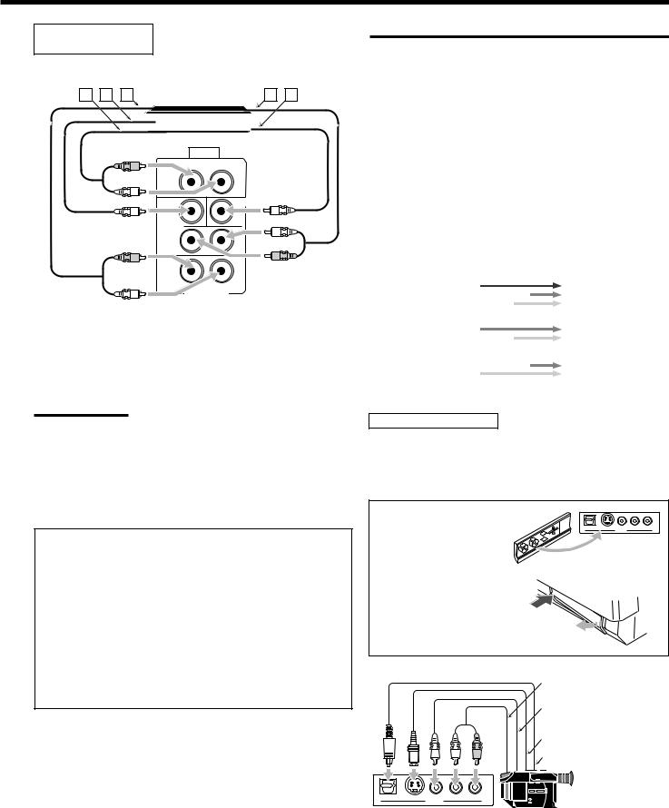
External 7.1-channel
output component
|
Decoder |
|
A B C |
(or DVD player) |
D E |
|
|
|
|
|
|
|
AUDIO |
R |
LEFT |
L |
|
|
CENTER |
|
WOOFER |
|
L |
|
SURR |
R |
R |
|
L |
L |
IN |
Å To left/right front channel output
ı To LFE channel (subwoofer) output
Ç To left/right surround back channel output Î To left/right surround channel output
‰ To center channel output
Note:
The ZIST circuit (see page 1) is incorporated for the EXT 7.1CH IN jacks to clarify the audio signals independently from the video input circuit.
However, if the external component connected to the EXT 7.1CH IN jacks and this receiver are not connected using video cords (composite, S- video, or component), noise may happen to be generated when listening to this external component.
In this case, connect the video output jacks on the external component and unused video input jacks on this receiver.
How to view the pictures through an external component connected to the EXT 7.1CH IN (audio input) jacks
The EXT 7.1CH IN jacks do not have any corresponding video input jack on the rear. You have to use one of the following methods to view the pictures through the external component.
•Connect the video output jack on the external component directly to the TV, and select the connected input on the TV.
•Connect the video output jack on the external component to any one of unused video input jacks on the rear, then...
1.Select that video input as the video source.
2.Select “EXT 7.1CH” as the audio source.
(See “Selecting different sources for picture and sound” on page 20).
Video component connections
Use cables with RCA pin plugs (not supplied).
Connect the white plug to the audio left jack, the red plug to the audio right jack, and the yellow plug to the video jack.
•If your video components have S-video (Y/C-separation) and/or component video (Y, PB, PR) jacks, connect them using an S-video cable (not supplied) and/or component video cable (not supplied). By using these jacks, you can get better picture quality—in the order: Component video > S-video > Composite video.
IMPORTANT:
This receiver is equipped with the following video jacks—composite video, S-video and component video jacks. You can use any of the three to connect a video component.
However, observe the following points when make connections:
•Composite video signals and S-video signals can be converted into each other, and can be also converted into component signals. So incoming signals of both types can be emitted through all video output jacks. (If both signals are used, the unit automatically gives priority to S-video signals.)
—Pictures may be distorted if the signals are converted. If this happens, connect the playback source component and TV using the cords of the same type.
•When the recording components and this unit are connected using the video cords or S-video cords, playback components and this unit need to be connected using the cords of the same type.
•Component signals cannot be converted. So incoming signals of this type can be emitted only through the component output jacks.
|
Video Input |
|
Converted |
|
Video Output |
|
|||
|
|
|
|
|
|
|
|
|
|
|
Component |
|
|
|
|
|
|
Component |
|
|
|
|
|
|
|
|
|
||
|
|
|
|
|
|
|
|
|
|
|
|
|
|
|
|
|
|
|
|
|
S-video |
|
|
|
|
|
|
S-video |
|
|
|
|
|
|
|
|
|
|
|
|
|
|
|
|
|
|
|
|
|
|
Video (composite) |
|
|
|
|
|
|
Video (composite) |
|
|
|
|
|
|
|
|
|
||
|
|
|
|
|
|
|
|
|
|
|
|
|
|
|
|
|
|
|
|
Video camera
The VIDEO input terminals on the front panel are convenient when connecting and disconnecting the component frequently.
•When you do not use the VIDEO input terminals, attach the front terminal cover (supplied) to these jacks to protect them from dust.
• When attaching the front |
|
|
terminal cover |
DIGITAL |
VIDEO |
|
S-VIDEO VIDEO L—AUDIO—R |
• When removing the cover
To audio output
To composite video output
|
To S-video output |
L R |
To optical digital output |
|
DIGITAL S-VIDEO VIDEO L—AUDIO—R
VIDEO
Video camera
When using the digital input terminal
Select the digital input mode correctly.
For details, see “Selecting the Analog or Digital Input Mode” on page 21.
12

NOTICE: If you play back an NTSC tape on a VCR, the picture may be distorted and may not be displayed correctly.
Rear view
VCR(s)
A B |
|
D-VHS/S-VHS/VHS |
C |
D E F G |
||
|
VCR |
|||||
|
|
|
|
|||
|
|
|
|
|
|
|
|
|
|
|
|
|
|
|
|
|
|
|
|
|
|
|
|
|
|
|
|
|
|
|
|
|
|
|
|
|
|
|
|
|
|
AUDIO |
|
|
VIDEO |
COMPONENT |
|
RIGHT |
LEFT |
VIDEO |
S-VIDEO |
||
|
|||||
|
|
TV SOUND |
|
|
|
|
|
DBS |
Y |
Y |
|
|
|
IN |
|
|
|
R |
|
OUT |
|
|
|
|
|
(REC) |
|
|
|
L |
|
VCR 1 |
1 IN |
2 |
|
|
|
|
|
||
R |
|
IN |
|
|
|
|
|
(PLAY) |
|
|
|
L |
|
|
|
|
|
|
|
OUT |
Y |
|
|
|
|
(REC) |
|
||
|
|
|
|
||
|
|
VCR 2 |
|
|
|
|
|
IN |
PB |
|
|
|
|
(PLAY) |
|
|
|
|
|
|
3 IN |
|
|
FRONT |
|
DVD |
PR |
|
|
|
IN |
|
|||
|
|
|
|
AUDIO |
|
|
|
VIDEO |
COMPONENT |
|
RIGHT |
LEFT |
VIDEO |
S-VIDEO |
|||
|
||||||
|
|
TV SOUND |
|
|
|
|
|
|
DBS |
|
Y |
Y |
|
|
|
IN |
|
|
|
|
|
|
OUT |
|
PB |
PB |
|
|
|
(REC) |
|
|||
|
|
VCR 1 |
|
1 IN |
2 |
|
|
|
|
(DVD) |
IN |
||
|
|
IN |
|
PR |
PR |
|
|
|
(PLAY) |
|
|
|
|
R |
|
OUT |
|
|
|
|
|
|
(REC) |
|
|
|
|
L |
|
VCR 2 |
|
|
|
|
|
|
|
|
|
||
R |
|
IN |
|
|
|
|
|
|
(PLAY) |
|
|
|
|
L |
|
|
|
3 IN |
|
|
FRONT |
|
DVD |
|
PR |
|
|
|
IN |
|
|
|||
|
|
|
|
|
||
SUB |
|
MONITOR |
|
|
|
|
S-VHS/VHS VCR |
Y |
|
||||
WOOFER |
|
|||||
|
|
OUT |
|
|
|
|
CENTER
SURR |
PB |
SURR |
|
PR |
|
BACK |
|
C D E F |
|
A B |
|
|
|
R |
L |
MONITOR OUT |
|
|
PREOUT |
|
|
13
Å To audio input ı To audio output
Ç To component video output Î To S-video output
‰ To composite video output Ï To S-video input
Ì To composite video input
Notes:
If the VCR has component video output jacks, you can connect it to either the COMPONENT 1 IN (DVD), 2 IN, or 3 IN jacks. When connecting the VCR to either one of the component input jacks, make the video input terminal setting correctly. For details, see “ p Setting the Video Input Terminals—VIDEO INPUT” on page 37.
Å To audio output ı To audio input
Ç To composite video input Î To S-video input
‰ To composite video output Ï To S-video output
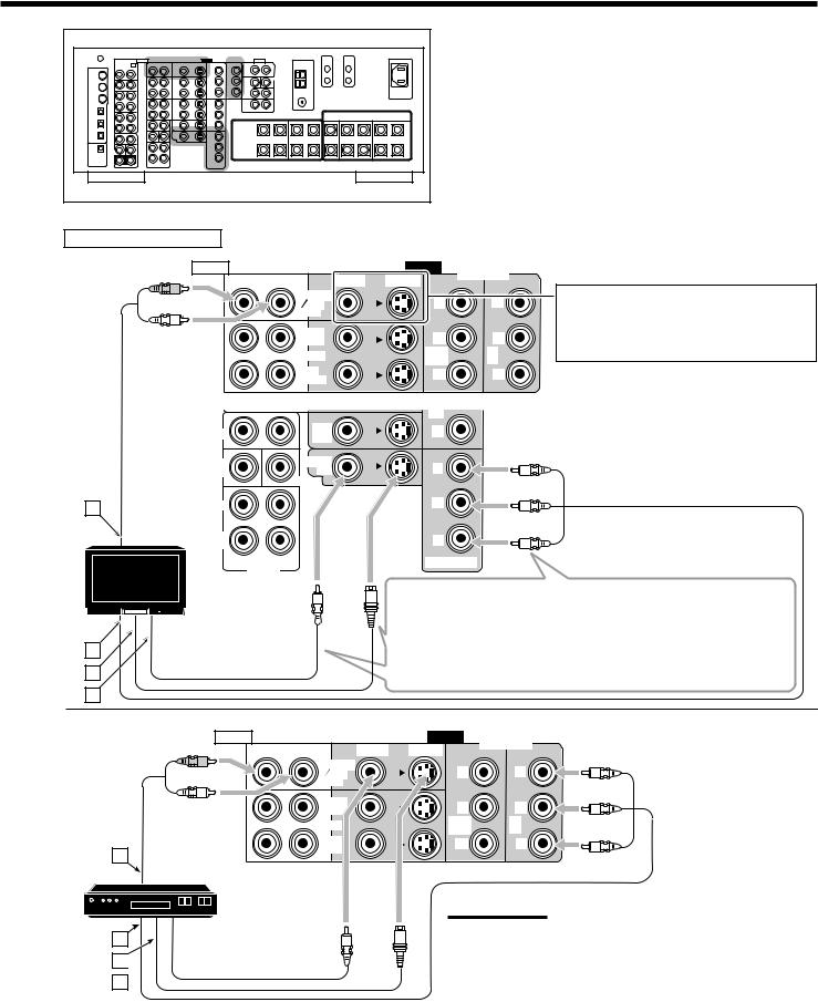
Rear view
TV and/or DBS tuner
AUDIO |
|
|
VIDEO |
COMPONENT |
|
RIGHT |
LEFT |
VIDEO |
S-VIDEO |
||
|
|||||
R |
|
TV SOUND |
|
|
|
|
|
|
|
||
|
|
DBS |
Y |
Y |
|
L |
|
IN |
|
|
|
|
|
|
|
||
|
|
OUT |
PB |
PB |
|
|
|
(REC) |
|||
|
|
VCR 1 |
1 IN |
2 |
|
|
|
(DVD) |
IN |
||
|
|
IN |
PR |
PR |
|
|
|
(PLAY) |
|
|
|
|
|
|
3 IN |
|
|
FRONT |
|
DVD |
PR |
|
|
|
IN |
|
|||
|
|
|
|
|
SUB |
MONITOR |
Y |
|
WOOFER |
OUT |
|
|
|
CENTER |
|
A |
SURR |
|
PB |
|
|
||
|
TV |
|
|
When connecting the TV to the AUDIO jacks (TV SOUND/DBS IN), DO NOT connect the TV’s video output to these video input jacks.
Å To audio output
ı To component video input Ç To S-video input
Î To composite video input
SURR |
PR |
|
BACK |
||
|
||
R |
L |
|
|
PREOUT |
B
C
D
Connect the TV to appropriate MONITOR OUT jacks to view the playback picture from the connected video components.
•Using the component cords allows you to view the playback picture from any other connected video components without using S-video or composite video connections.
AUDIO |
|
|
VIDEO |
COMPONENT |
|
RIGHT |
LEFT |
VIDEO |
S-VIDEO |
||
|
|||||
R |
|
TV SOUND |
|
|
|
|
|
DBS |
Y |
Y |
|
|
|
IN |
|
|
|
L |
|
OUT |
|
|
|
|
|
PB |
PB |
||
|
|
(REC) |
|||
|
|
VCR |
1 IN |
2 |
|
|
|
(DVD) |
IN |
||
|
|
IN |
PR |
PR |
|
A |
|
(PLAY) |
|
|
|
|
|
|
|
DBS tuner
DBS
B
C 
D
Å To audio output
ı To component video output Ç To S-video output
Î To composite video output
Notes:
•When connecting the DBS tuner to the TV SOUND/DBS IN jacks, change the source name to “DBS,” which will be shown on the display when selected as the source. See “Changing the Source
Name” on page 23 for details.
•If the DBS tuner has component video output jacks, you can connect it to either the COMPONENT 1 IN (DVD), 2 IN, or 3 IN jacks. When connecting the DBS tuner to either one of the component input jacks, make the video input terminal setting correctly. For details, see
“ p Setting the Video Input Terminals—VIDEO INPUT” on page 37.
14
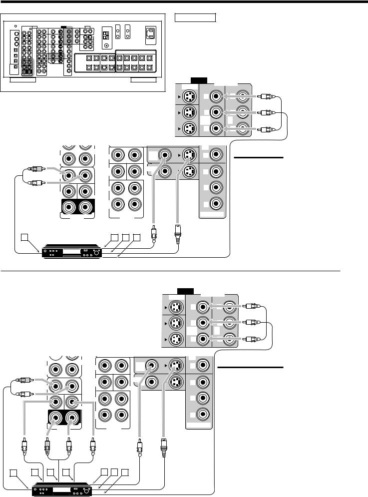
Rear view
ÅTo front left/right channel audio output (or to audiomixed output if necessary)
ı To composite video output Ç To S-video output
Î To component video output
(REC) |
|
CDR |
|
|
|
|
|
DVD |
|
IN |
|
FRONT |
|
|
|
|
|
||
(PLAY) |
|
|
|
|
R |
|
SUB |
|
|
|
|
WOOFER |
|
CENTER |
|
|
|
|
|
L |
|
|
|
|
|
|
SURR |
|
|
SUB |
|
|
|
|
WOOFER |
|
CENTER |
|
|
SURR |
|
SURR |
|
|
|
BACK |
|
|
|
(REAR) |
|
|
|
|
|
|
|
|
|
R |
DVD IN |
L |
R |
L |
|
PREOUT |
|||
|
|
|
A |
DVD player |
B C D |
DVD |
DVD player
• When you connect the DVD player with stereo output jacks:
VIDEO
S-VIDEO |
COMPONENT |
|
|
Y |
|
PB |
|
1 IN |
2 |
(DVD) |
IN |
PR |
|
3 IN |
|
PR
Y
PB
PR
MONITOR OUT
Note:
If the DVD player has component video output jacks, you can connect it to either the
COMPONENT 1 IN (DVD), 2 IN, or 3 IN jacks. When connecting the DVD player to either one of the component input jacks, make video input terminal setting correctly.
For details, see “ p Setting the Video Input Terminals—VIDEO INPUT” on page 37.
•When you connect the DVD player with its analog discrete output (5.1-channel reproduction) jacks:
Å To left/right front channel audio output ı To subwoofer (LFE) output
Ç To left/right surround channel audio output Î To center channel audio output
‰ To composite video output Ï To S-video output
Ì To component video output
(REC) 
|
CDR |
|
IN |
FRONT |
|
(PLAY) |
|
|
R |
SUB |
|
|
WOOFER |
CENTER |
|
|
|
L |
|
|
DVD |
R |
L |
|
PREOUT |
VIDEO
S-VIDEO
Y
PB
1 IN (DVD)
PR
3 IN
PR
Y
PB
PR
COMPONENT
2 IN
Note:
If the DVD player has component video output jacks, you can connect it to either the
COMPONENT 1 IN (DVD), 2 IN, or 3 IN jacks.
When connecting the DVD player to either one of the component input jacks, make video input terminal setting correctly. For details, see “ p
Setting the Video Input Terminals—VIDEO INPUT” on page 37.
MONITOR OUT
|
R |
L |
A |
B C D |
E F G |
DVD |
DVD player
15
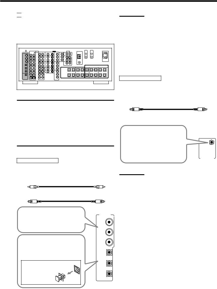

 Digital Connections
This receiver is equipped with six DIGITAL IN terminals—three digital coaxial terminals and three digital optical terminals—and one DIGITAL OUT (optical) terminal on the rear.
•Another digital optical input terminal is located on the front panel (see page 12).
Rear view
IMPORTANT:
•When connecting the DVD player, digital TV broadcast tuner, digital VCR, or DBS tuner using the digital terminals, you also need to connect it to the video terminal on the rear. Without connecting it to the video terminal, you cannot view any playback picture.
•After connecting the components using the DIGITAL IN terminals, set the following correctly if necessary:
–Set the digital input (DIGITAL IN) terminal setting correctly. For details, see “9 Setting the Digital Input/Output Terminals— DIGITAL IN/OUT” on page 36.
–Select the digital input mode correctly. For details, see “Selecting the Analog or Digital Input Mode” on page 21.
Digital input terminals
You can connect any digital components having a coaxial or optical digital output terminal.
Digital coaxial cable (not supplied) between digital coaxial terminals
Digital optical cable (not supplied) between digital optical terminals
When the component has a digital
coaxial output terminal, connect it to the DIGITAL IN 1 (DVD), 2 (CD), or 3 (TV/DBS) terminal,
(DVD)
using a digital coaxial cable (not supplied).
|
(CD) |
|
When the component has a digital |
(TV |
|
optical output terminal, connect it to the |
||
/DBS) |
||
4 (CDR), 5 (MD), or 6 (VCR 1) terminal, |
|
|
using a digital optical cable (not |
|
|
supplied). |
(CDR) |
|
Before connecting a digital |
(MD) |
|
optical cable, unplug the |
||
|
||
protective plug. |
|
|
|
(VCR 1) |
Notes:
•When shipped from the factory, the DIGITAL IN terminals have been set for use with the following components:
– 1 (coaxial) |
: For DVD player |
|
– 2 (coaxial) |
: For CD player |
|
– 3 |
(coaxial) |
: For digital TV broadcast tuner |
– 4 |
(optical) |
: For CD recorder |
– 5 |
(optical) |
: For MD recorder |
– 6 |
(optical) |
: For VCR 1 (VCR connected to the VCR 1 jacks) |
•When you want to operate the CD player, CD recorder, or MD recorder using the COMPU LINK or TEXT COMPU LINK remote control system, connect the target component also as described in “Analog Connections” (see page 11).
Digital output terminal
You can connect any digital component which have an optical digital input terminal.
Digital optical cable (not supplied) between digital optical terminals
When digital recording equipment |
|
|
such as an MD recorder and a CD |
|
|
recorder has a digital optical input |
|
|
|
|
|
terminal, connecting it to the |
|
|
DIGITAL OUT terminal enables you |
DIGITAL |
|
to perform digital-to-digital |
|
|
recording. |
|
|
|
OUT |
|
|
|
|
Note:
The format of the digital signals transmitted through the DIGITAL OUT terminal can be determined using the Setup Menu.
For details, see “ 9 Setting the Digital Input/Output Terminals—
DIGITAL IN/OUT” on pages 36 and 37.
16
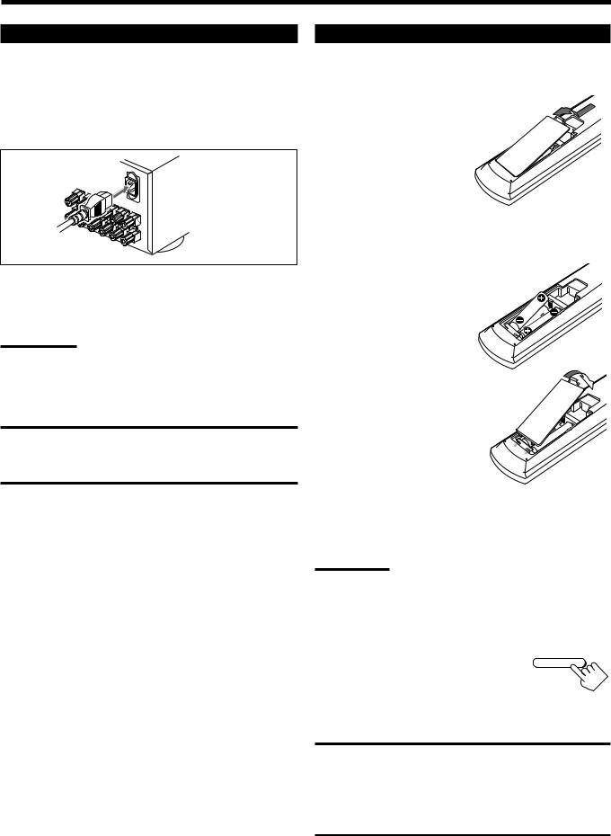
Connecting the Power Cord
Before plugging the receiver into an AC outlet, make sure that all connections have been made.
Connect one end of the power cord to the  AC IN socket on the rear and the other end into an AC outlet.
Keep the power cord away from the connecting cables and the antenna. The power cord may cause noise or screen interference.
Note:
The preset settings such as preset channels and sound adjustment may be erased in a few days in the following cases:
–When you unplug the power cord.
–When a power failure occurs.
CAUTIONS:
•Do not touch the power cord with wet hands.
•Do not pull on the power cord to unplug the cord.
When unplugging the cord, always grasp the plug so as not to damage the cord.
Putting Batteries in the Remote Control
Before using the remote control, insert the two supplied batteries first.
1. On the back of the remote control, remove the battery cover.
2.Insert the batteries.
• Make sure to match the polarity:
(+) to (+) and (–) to (–).
LR6(AM3)/L40(15A)
3. Replace the cover.
If the remote control cannot transmit signals or operate the receiver correctly, replace the batteries. Use two LR6(AM3)/L40(15A) type (alkaline) dry-cell batteries.
Notes:
•If you aim the remote control directly at the remote sensor on the receiver, you can operate the receiver at a distance of up to 7 m.
•When replacing the batteries, finish changing them without delay; otherwise, the stored signals are all erased (see pages 64 to 70).
When using the remote control in the dark
Press LIGHT.
LIGHT
The buttons on the remote control are backlit while you are using the remote control.
If you do not press any button for about 5 seconds, the backlight will turn off.
CAUTIONS:
Follow these precautions to avoid leaking or cracking cells:
•Place batteries in the remote control so they match the polarity:
(+) to (+) and (–) to (–).
•Use the correct type of batteries. Batteries that look similar may differ in voltage.
•Always replace both batteries at the same time.
•Do not expose batteries to heat or flame.
17

 Basic Operations
This section explains only the operations commonly used when you play any sound source.
•Before performing basic operations, it is recommended to finish the basic settings on pages 29 to 38.
IMPORTANT:
• When using the unit:
Press DOOR DOWN to use the buttons inside the |
DOOR |
DOWN |
|
front door. |
|
To close the front door, press DOOR UP. |
|
•When using the remote control:
Check the indication shown on the remote’s display when you press a button—this indicates the remote control operation mode for a while.
DVD AUDIO
TRANSMIT
TV/DBS |
VCR 1 |
LEARN TRANSMIT
Ex. When you press FM/AM.
Simple Operating Procedure
4. |
If no sound comes out of the front |
SPEAKERS 1 |
|
speakers, press SPEAKERS 1 |
|
and/or SPEAKERS 2 which you |
SPEAKERS 2 |
|
|
want to use. |
|
The selected front speaker indicator(s) light(s) up on the display.
•For more details, see “Activating the Front Speakers” on page 21.
5. Turn MASTER VOLUME to |
MASTER VOLUME |
|
|
adjust the volume level of the |
|
sound through the speakers. |
|
Down |
Up |
From the remote control:
1. Set LEARN/TRANSMIT selector to
“TRANSMIT.”
LEARN TRANSMIT
On the unit:
1. Press  (STANDBY/ON).
The STANDBY lamp goes off, and the front door moves down so that the source selecting buttons appear.
•For more details, see “Turning the Power On and Off (Standby)” on page 19.
 STANDBY
STANDBY/ |
|
The last source is activated. |
|
ANALOG |
SPEAKERS 1 |
L R |
|
SUBWFR |
VOLUME |
|
dB |
The last Surround/THX/DSP |
The volume |
mode appears. |
level appears. |
2. Press AUDIO . |
AUDIO |
The STANDBY lamp goes off, and the front door moves down.
•For more details, see “Turning the Power On and Off (Standby)” on page 19.
The last source is activated.
ANALOG
L R |
SPEAKERS 1 |
SUBWFR |
VOLUME |
|
dB |
The last Surround/THX/DSP |
The volume |
mode appears. |
level appears. |
3. Select and play a source.
DVD |
DVD MULTI |
PHONO |
CD |
VCR 1 |
VCR 2 |
TAPE/MD |
CDR |
TV/DBS |
VIDEO |
FM/AM |
EXT 7.1CH |
2. Select and play a source.
DVD DVD MULTI VCR 1 |
VCR 2 |
TV/DBS |
VIDEO |
CD |
PHONO TAPE/MD |
CDR |
FM/AM EXT 7.1CH |
3. Press DOOR DOWN so that you can use the other buttons inside the front door.
DOOR
DOWN
To close the front door, press DOOR UP once or twice.
The front door moves up in two steps.
The sound comes out of the front speakers.
•If no sound comes out of the front speakers, press SPEAKERS 1 and/or SPEAKERS 2 on the unit (inside the front door).
The selected front speaker indicator(s) light(s) up on the display. For more details, see “Activating the Front Speakers” on page 21.
4. Press VOLUME +/– to adjust the
volume level of the sound through |
VOLUME |
|
the speakers. |
||
|
18
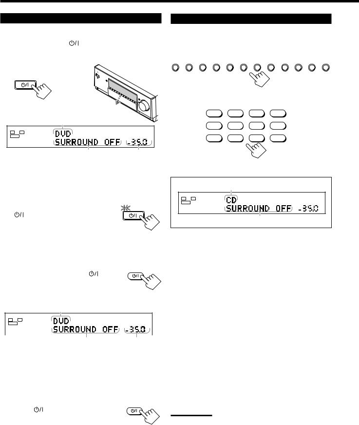
Turning the Power On and Off (Standby)
On the unit: |
|
To turn on the power, press |
(STANDBY/ON). |
The STANDBY lamp goes off, and the front door moves down (so that the source selecting buttons appear).
 STANDBY
STANDBY/
The last source is activated.
ANALOG |
SPEAKERS 1 |
L R |
|
SUBWFR |
VOLUME |
|
dB |
The last Surround/THX/DSP mode |
The volume |
appears. |
level appears. |
The currently selected speakers 1 and/or 2 indicator(s) also light(s) up on the display.
•If neither speakers 1 nor 2 indicator is lit on the display, see “Activating the Front Speakers” on page 21.
To turn off the power (into standby mode),
press |
(STANDBY/ON) again. |
The STANDBY lamp lights up, and the front door automatically closes.
•A small amount of power is consumed in standby mode. To turn the power off completely, unplug the AC power cord.
From the remote control:
AUDIO
To turn on the power, press AUDIO .
The STANDBY lamp goes off, and the front door moves down (so that the source selecting buttons appear).
The last source is activated.
|
ANALOG |
SPEAKERS |
1 |
|
L |
R |
|||
|
|
|||
SUBWFR |
|
VOLUME |
||
|
dB |
|
|
The last Surround/THX/DSP |
The volume |
mode appears. |
level appears. |
The currently selected speakers 1 and/or 2 indicator(s) also light(s) up on the display.
•If neither speakers 1 nor 2 indicator is lit on the display, see “Activating the Front Speakers” on page 21.
To turn off the power (into standby mode),
press AUDIO |
AUDIO |
again. |
The STANDBY lamp lights up, and the front door automatically closes.
Selecting the Source to Play
Press one of the source selecting buttons.
•The selected source name and Surround/THX/DSP mode also appear on the display.
DVD DVD MULTI VCR 1 |
VCR 2 |
TV/DBS |
VIDEO |
CD |
PHONO TAPE/MD |
CDR |
FM/AM EXT 7.1CH |
On the unit
DVD |
DVD MULTI |
PHONO |
CD |
VCR 1 |
VCR 2 |
TAPE/MD |
CDR |
TV/DBS |
VIDEO |
FM/AM |
EXT 7.1CH |
|
|
From the remote control |
|
|
Selected source name |
ANALOG |
SPEAKERS 1 |
|
L |
R |
|
SUBWFR |
|
VOLUME |

 dB
dB
The current Surround/THX/DSP mode appears.
DVD : Selects the DVD player.
DVD MULTI : Selects the DVD player for viewing a digital video
|
disc using the analog discrete output mode (5.1- |
|
channel reproduction). |
|
To use the DVD MULTI playback mode, see page 54. |
VCR 1 |
: Selects the video component connected to the VCR 1 |
|
IN jacks. |
VCR 2 |
: Selects the video component connected to the VCR 2 |
|
IN jacks. |
TV/DBS |
: Selects TV sound (or the DBS tuner). |
VIDEO |
: Selects the video component connected to the VIDEO |
|
jacks. |
CD* |
: Selects the CD player. |
PHONO* |
: Selects the turntable. |
TAPE/MD* |
: Selects the cassette deck (or the MD recorder). |
CDR* |
: Selects the CD recorder. |
FM/AM* |
: Selects the tuner. |
|
Each time you press the button, the band alternates |
|
between FM and AM (MW/LW). |
EXT 7.1CH |
: Selects the external component connected to the EXT |
|
7.1CH IN jacks. |
|
To use the EXT 7.1CH playback mode, see page 54. |
Notes:
•When connecting an MD recorder (to the TAPE/MD IN jacks), and a DBS tuner (to the TV SOUND/DBS IN jacks), change the source names shown on the display. For details, see “Changing the Source Name” on page 23.
•When you press one of the audio source selecting buttons on the remote control marked with an asterisk (*), the receiver automatically turns on.
19
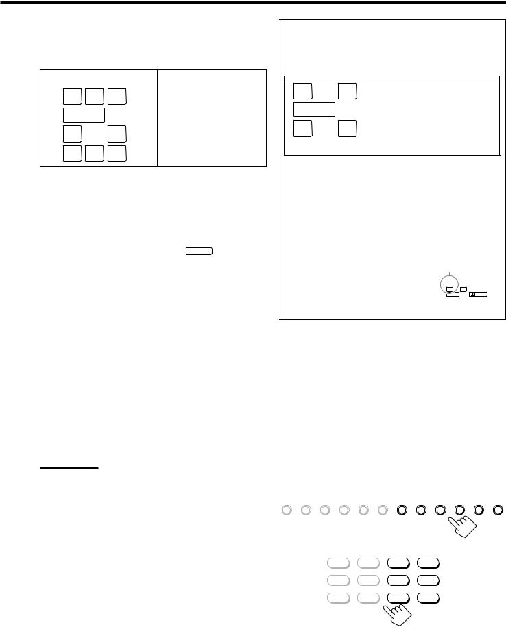
Speaker and signal indicators on the display
By checking the following indicators, you can easily confirm which speakers you are activating and which signals are coming into this receiver from the source.
Speaker indicators |
Signal indicators |
L C |
R |
L |
C |
R |
SUBWFR |
|
|
|
LFE |
LS |
RS |
LS |
S |
RS |
SB |
|
|
SB |
|
What speaker indicators light depends on the speaker setting (for details, see “1 Setting the Speakers—SPEAKER
SETTING” on page 32).
•The frames of “L,” “C,” “R,” “LS,” “RS, ” and “SB” light up, when the corresponding speakers are set to “LARGE” or “SMALL” and when the speaker is required for the Surround/
THX/DSP mode currently selected.
• When “SUBWOOFER” is set to “YES,” SUBWFR lights up.
•All three frames on the row of “SB” are not used at the same time. When “SURR BACK OUT” is set to “2SPK,” the left and the right ones are used. When it is set to “1SPK,” the middle one is used.
The signal indicators light up to show the incoming signals.
L : • When digital input is selected: Lights up when the left channel signal comes in.
• When analog input is selected: Always lights up.
R : • When digital input is selected: Lights up when the right channel signal comes in.
• When analog input is selected: Always lights up.
C : Lights up when the center channel signal comes in. LFE : Lights up when the LFE channel signal comes in.
LS : Lights up when the left surround channel signal comes in. RS : Lights up when the right surround channel signal comes in. S : Lights up when the monaural surround channel signal
comes in.
SB : Lights up when the surround back channel signal comes in.
Notes:
•When “DVD MULTI” is selected as the source, “L,” “C,” “R,” “LFE,”
“LS” and “RS” light up.
•When “EXT 7.1CH” is selected as the source, “L,” “C,” “R,” “LFE,”
“LS,” “RS,” and “SB (left/right)” light up.
However, “SB” will not light if the THX mode or the DSP mode is activated or if “SPEAKER 2” is set to “BI-AMP OUT” (see page 37).
How to use the speaker and signal indicators
To obtain the best performance of this receiver while using the Surround/THX/DSP modes, check the speaker and signal indicators on the display carefully and set the speakers correctly.
L |
C R |
Ex. No sound comes out of the |
SUBWFR LFE |
center speaker and surround |
|
back speakers though center |
||
LS |
RS |
channel and surround back |
channel signals are coming |
||
into this receiver.
SB
About Dual Mono
Dual Mono can be easily understood when you think of the bilingual broadcast used for TV programs (however, the Dual Mono format is not identical with those analog formats).
This format is now adopted in Dolby Digital, DTS, and so on. It allows two independent channels (called main channel and subchannel) to be recorded separately.
• When Dual Mono signals are detected, the
DUAL indicator lights up. |
DUAL indicator |
|
You can select either channel you want to |
|
|
listen to (see page 36). |
DUAL |
DGTL AUTO |
|
L |
R |
|
SUBWFR |
DIGITAL |
|
|
|
Selecting different sources for picture and sound
While watching pictures from a video source (DVD player, VCR, or DBS tuner), you can listen to sound of an audio source.
•Once you have selected a video source, pictures of the selected source are sent to the TV until you select another video source.
Press one of the audio source selecting buttons— PHONO, CD, TAPE/MD, CDR, FM/AM,
EXT 7.1CH—while viewing the picture from a video component such as the VCR or DVD player, etc.
DVD DVD MULTI VCR 1 VCR 2 TV/DBS VIDEO CD PHONO TAPE/MD CDR FM/AM EXT 7.1CH
On the unit
DVD |
DVD MULTI |
PHONO |
CD |
VCR 1 |
VCR 2 |
TAPE/MD |
CDR |
TV/DBS |
VIDEO |
FM/AM |
EXT 7.1CH |
From the remote control
20
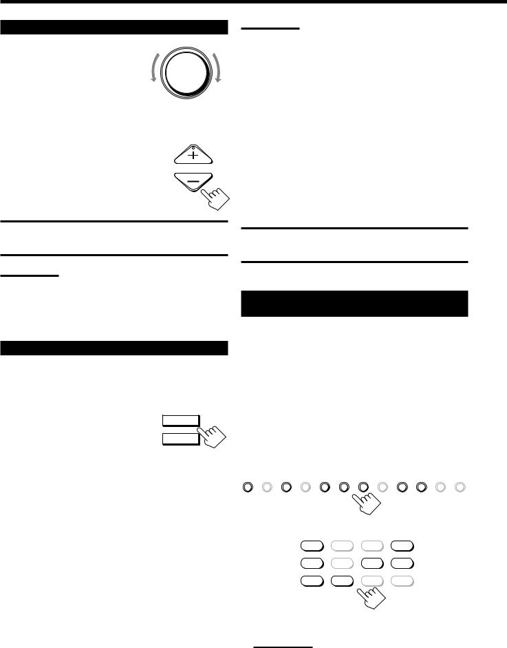
Adjusting the Volume
On the unit: |
|
MASTER VOLUME |
|
|
|
To increase the volume, turn MASTER |
|
|
VOLUME clockwise. |
|
|
To decrease the volume, turn it |
Down |
Up |
counterclockwise. |
•When you turn MASTER VOLUME rapidly, the volume level also changes rapidly.
•When you turn MASTER VOLUME slowly, the volume level also changes slowly.
From the remote control:
To increase the volume, press VOLUME +. |
VOLUME |
|
To decrease the volume, press VOLUME –. |
||
|
CAUTION:
Always set the volume to the minimum before starting any source. If the volume is set at a high level, the sudden blast of sound energy can permanently damage your hearing and/or ruin your speakers.
Notes:
•The volume level can be adjusted within the range of “– – – dB” (minimum), “–71.0 dB” to “+18.0 dB” (maximum).
•If you set One Touch Operation to “ON” (see page 38), you do not have to adjust the volume level each time you change the source. It is automatically set to the stored level.
Activating the Front Speakers
When you have connected two pairs of the front speakers, you can select which to use.
On the unit ONLY: |
|
To use the speakers connected to the FRONT |
SPEAKERS 1 |
1 SPEAKERS terminals, press SPEAKERS 1 |
|
(inside the front door) so that the speakers 1 |
SPEAKERS 2 |
indicator lights up on the display. (Make sure |
|
that the speakers 2 indicator is not lit on the display.)
To use the speakers connected to the FRONT 2 SPEAKERS terminals, press SPEAKERS 2 (inside the front door) so that the speakers 2 indicator lights up on the display. (Make sure that the speakers 1 indicator is not lit on the display.)
To use both sets of the speakers, press SPEAKERS 1 and SPEAKERS 2 so that the speakers 1 and 2 indicators light up on the display.
To use neither set of the speakers, press SPEAKERS 1 and SPEAKERS 2 so that the speakers 1 and 2 indicators disappear from the display.
(“HEADPHONE” appears on the unit’s display.)
Notes:
•In the following cases, the speakers connected to the FRONT 2
SPEAKERS terminals are deactivated even if both pairs of the front speakers are activated.
–If you select “DVD MULTI” or “EXT 7.1CH” as the source, or
–If you select one of the Surround/THX/DSP modes.
•The SPEAKERS 2 button will not work if “SPEAKER 2” is set to “BIAMP OUT” (see page 37).
Listening with headphones only:
Sounds through the front speakers and the subwoofer shut off when connecting a pair of headphones to the PHONES jack. (“HEADPHONE” appears on the unit’s display.)
You can enjoy the following sound effects through the headphones:
•If the Surround/THX mode is activated, you can enjoy surround effect. (For details, see “3D HEADPHONE Mode” on page 51.)
•If a DSP mode is activated, you can enjoy the DSP effect. (For details, see “HEADPHONE Mode” on page 52.)
CAUTION:
Be sure to turn down the volume before connecting or putting on headphones, as high volume can damage both the headphones and your hearing.
Selecting the Analog or Digital Input Mode
When you have connected digital source components using the digital terminals (see pages 12 and 16), you need to select the digital input mode.
Before you start, remember...
The digital input (DIGITAL IN) terminal setting should be properly done (see “9 Setting the Digital Input/Output
Terminals—DIGITAL IN/OUT” on page 36).
1.Press one of the source selecting buttons (DVD, VCR 1, TV/DBS, VIDEO, CD, CDR, or TAPE/ MD*) for which you want to change the input mode.
DVD DVD MULTI VCR 1 |
VCR 2 |
TV/DBS |
VIDEO |
CD |
PHONO TAPE/MD |
CDR |
FM/AM EXT 7.1CH |
On the unit
DVD |
DVD MULTI |
PHONO |
CD |
VCR 1 |
VCR 2 |
TAPE/MD |
CDR |
TV/DBS |
VIDEO |
FM/AM |
EXT 7.1CH |
From the remote control
Note:
*If “TAPE” has been assigned to the TAPE/MD button, it does not work in this step.
To change the source name, see “Changing the Source Name” on page 23.
21
 Loading...