


AUDIO/VIDEO CONTROL RECEIVER
RX-D411S/RX-D412B
INSTRUCTIONS
For Customer Use:
Enter below the Model No. and Serial No. which are located either on the rear, bottom or side of the cabinet. Retain this information for future reference.
Model No.
Serial No.
LVT1572-001A
[J]
Warnings, Cautions, and Others
Mises en garde, précautions et indications diverses
|
|
CAUTION |
|
|
|
RISK OF ELECTRIC SHOCK |
|
|
|
DO NOT OPEN |
|
|
|
|
|
|
|
|
|
CAUTION: |
TO REDUCE THE RISK OF ELECTRIC SHOCK, |
||
|
DO NOT REMOVE COVER (OR BACK). |
||
|
NO USER SERVICEABLE PARTS INSIDE. |
||
REFER SERVICING TO QUALIFIED SERVICE PERSONNEL.
The lightning flash with arrowhead symbol, within an equilateral triangle is intended to alert the user to the presence of uninsulated "dangerous voltage" within the product's enclosure that may be of sufficient magnitude to constitute a risk of electric shock to persons.
The exclamation point within an equilateral triangle is intended to alert the user to the presence of important operating and maintenance (servicing) instructions in the literature accompanying the appliance.
WARNING: TO REDUCE THE RISK OF FIRE OR ELECTRIC SHOCK, DO NOT EXPOSE THIS APPLIANCE TO RAIN OR MOISTURE.
CAUTION
To reduce the risk of electrical shocks, fire, etc.:
1.Do not remove screws, covers or cabinet.
2.Do not expose this appliance to rain or moisture.
ATTENTION
Afin d’éviter tout risque d’électrocution, d’incendie, etc.:
1.Ne pas enlever les vis ni les panneaux et ne pas ouvrir le coffret de l’appareil.
2.Ne pas exposer l’appareil à la pluie ni à l’humidité.
Caution––  STANDBY/ON button!
Disconnect the mains plug to shut the power off completely (the standby lamp goes off). When installing the apparatus, ensure that the plug is easily accessible. The  STANDBY/ON button in any position does not disconnect the mains line.
•When the unit is on standby, the standby lamp lights red.
•When the unit is turned on, the standby lamp goes off. The power can be remote controlled.
Attention—Touche  STANDBY/ON!
Déconnectez la fiche secteur pour mettre l’appareil complètement hors tension (le témoin d’attente s’éteint). Lors de l’installation de l’appareil, assurez-vous que la fiche soit facilement accessible. La touche  STANDBY/ON dans n’importe quelle position ne déconnecte pas l’appareil du secteur.
•Quand l’appareil est en mode d’attente, le témoin d’attente s’allume en rouge.
•Quand l’appareil est sous tension, le témoin d’attente s’éteint.
L’alimentation ne peut pas être commandée à distance.
Note to CATV system installer:
This reminder is provided to call the CATV system installer’s attention to Section 820-40 of the NEC which provides guidelines for proper grounding and, in particular, specifies that the cable ground shall be connected to the grounding system of the building, as close to the point of cable entry as practical.
CAUTION
Changes or modifications not approved by JVC could void the user’s authority to operate the equipment.
ATTENTION
Des changements ou modifications non approuvés par JVC pourront invalider l’autorité de l’utilisateur à opérer cet appareil.
For U.S.A
This equipment has been tested and found to comply with the limits for a Class B digital device, pursuant to part 15 of the FCC Rules. These limits are designed to provide reasonable protection against harmful interference in a residential installation.
This equipment generates, uses and can radiate radio frequency energy and, if not installed and used in accordance with the instructions, may cause harmful interference to radio communications. However, there is no guarantee that interference will not occur in a particular installation. If this equipment does cause harmful interference to radio or television reception, which can be determined by turning the equipment off and on, the user is encouraged to try to correct the interference by one or more of the following measures:
-Reorient or relocate the receiving antenna.
-Increase the separation between the equipment and receiver.
-Connect the equipment into an outlet on a circuit different from that to which the receiver is connected.
-Consult the dealer or an experienced radio/TV technician for help.
Declaration of Conformity:
Trade Name: JVC
Model Number: RX-D411S/RX-D412B
Responsible Party: JVC Americas Corp.
Address: 1700 Valley Road, Wayne New Jersey 07470 Telephone Number: 973-317-5000
This device complies with Part 15 of the FCC Rules. Operation is subject to the following two conditions:
(1)This device may not cause harmful interference.
(2)This device must accept any interference received, including interference that may cause undesired operation.
For Canada/pour Le Canada
THIS DIGITAL APPARATUS DOES NOT EXCEED THE CLASS B LIMITS FOR RADIO NOISE EMISSIONS FROM DIGITAL APPARATUS AS SET OUT IN THE INTERFERENCECAUSING EQUIPMENT STANDARD ENTITLED “DIGITAL APPARATUS,” ICES-003 OF THE DEPARTMENT OF COMMUNICATIONS.
CET APPAREIL NUMERIQUE RESPECTE LES LIMITES DE BRUITS RADIOELECTRIQUES APPLICABLES AUX APPAREILS NUMERIQUES DE CLASSE B PRESCRITES DANS LA NORME SUR LE MATERIEL BROUILLEUR; “APPAREILS NUMERIQUES”, NMB-003 EDICTEE PAR LE MINISTRE DES COMMUNICATIONS.
[European Union Only]
[Union européenne seulement]
G-1

Introduction
We would like to thank you for purchasing one of our JVC products.
Before operating this unit, read this manual carefully and thoroughly to obtain the best possible performance from your unit, and retain this manual for future reference.
Features
Hybrid Feedback Digital Amplifier
RX-D411S/RX-D412B features the JVC-exclusive Hybrid Feedback Digital Amplifier. Premium-grade parts and devices, and special internal construction assure you will enjoy superior sound.
Compatible with HDMI*
The HDMI (High-Definition Multimedia Interface) is the standard interface for the next-generation TV. By connecting the source components, this receiver, and TV with the HDMI cables, digital video signals and audio signals (including Dolby Digital, DTS) are transmitted through the cables. You can transmit digital video signal and audio signal without AD/DA conversion with easy connection.
As RX-D411S/RX-D412B supports up to HDMI version 1.1, this receiver can digitally receive 5.1-channel PCM with fs 96 kHz and 2-channel PCM with fs 192 kHz. (These PCM signals are referred to as “multi-channel PCM” in this instructions.) You can enjoy digital sound without deterioration. In addition, this receiver is compatible with HDCP** (High-bandwidth Digital Content Protection), and HDCP contents can be viewed if you connect an HDCP-compatible TV to this receiver.
*HDMI, the HDMI logo and High-Definition Multimedia Interface are trademarks or registered trademarks of HDMI Licensing LLC.
**HDCP is the abbreviation of “High-bandwidth Digital Content Protection,” and is the high-reliable copy control technology licensed by Digital Content Protection, LLC.
7.1 channel DAP (Digital Acoustic Processor)
Sound field simulation technology allows precise ambience recreation of existing theatres and halls. Thanks to the highperformance DSP (Digital Signal Processor) and high-capacity memory, you can enjoy 7.1-channel surround by playing 2-channel or multi-channel software.
Precise Surround Setup
Precise Surround Setup is a newly-developed JVC solution for quick, easy and systematic optimization of surround sound. By using Precise Surround Setup, you can enjoy the best possible surround performance. Precise Surround Setup measures the listening environment accurately with the dedicated earphone-type microphones and adjusts the speaker settings automatically.
CC (Compression Compensative) Converter
CC Converter eliminates jitter and ripples, achieving a drastic reduction in digital distortion by processing the digital music data in 24 bit–quantization and by expanding the sampling frequency to 128 kHz (for fs 32 kHz signals)/176.4 kHz (for fs 44.1 kHz signals)/192 kHz (for fs 48 kHz signals). By using the CC Converter, you can obtain a natural sound field from any source.
DCDi technology
DCDi (Directional Correlational Deinterlacing) technology, developed by Faroudja, eliminates jagged edges generated in progressive scanning conversion. With DCDi, you can enjoy clear and smooth video images on your display. For RX- D411S/RX-D412B, this function is applied only when the NTSC analog video signals are transmitted to the receiver.
K2 technology
K2 technology has been designed to enable natural audio reproduction, achieving a drastic reduction in digital distortion and creating original sound ambience with high precision.
Precautions
Power sources
•When unplugging the receiver from the wall outlet, always pull the plug, not the AC power cord.
•Do not handle the AC power cord with wet hands.
•If you are not going to operate the receiver for an extended period of time, unplug the AC power cord from the wall outlet.
Ventilation
The seven high power amplifiers built in this receiver will generate heat inside the cabinet.
For safety, observe the following carefully:
•Make sure there is good ventilation around the receiver. Poor ventilation could overheat and damage the receiver.
•Do not block the ventilation openings or holes. (If the ventilation openings or holes are blocked by a newspaper or cloth, etc., the heat may not be able to get out.)
Others
•Should any metallic object or liquid fall into the receiver, unplug the receiver and consult your dealer before operating any further.
•Do not use this receiver in a bathroom or places with water.
•Do not place any containers filled with water or liquids (such as cosmetics or medicines, flower vases, potted plants, cups, etc.) on the top of this receiver.
•Do not disassemble the receiver since there are no user serviceable parts inside.
If anything goes wrong, unplug the AC power cord and consult your JVC dealer.
1

Table of Contents
Parts identification...................................................... |
3 |
Getting started ............................................................ |
6 |
Before installation ............................................................................. |
6 |
Checking the supplied accessories ............................................. |
6 |
Putting the batteries in the remote control............................. |
6 |
Connecting the antennas............................................................... |
7 |
Connecting the speakers ................................................................ |
8 |
Connecting video components.................................................... |
9 |
Connecting the power cord........................................................ |
14 |
USB connection............................................................................... |
15 |
Precise Surround Setup ............................................ |
16 |
Setting the speakers automatically.......................................... |
16 |
Troubleshooting for Precise Surround Setup....................... |
19 |
Basic operations ........................................................ |
20 |
1 Turn on the power.................................................................. |
20 |
2 Select the source to play ...................................................... |
20 |
3 Adjust the volume .................................................................. |
21 |
Selecting the video and audio input settings ...................... |
21 |
Selecting the digital decode mode.......................................... |
22 |
Turning off the sounds temporarily......................................... |
22 |
Changing the display brightness.............................................. |
22 |
Turning off the power with the Sleep Timer ........................ |
23 |
Making sounds natural................................................................. |
23 |
FM/AM tuner operations........................................... |
24 |
Tuning in to stations manually .................................................. |
24 |
Using preset tuning ....................................................................... |
24 |
Selecting the FM reception mode............................................ |
25 |
XM Satellite Radio operations.................................. |
26 |
Preparation ....................................................................................... |
26 |
Listening to the XM Satellite Radio .......................................... |
26 |
Using preset tuning ....................................................................... |
27 |
Changing the channel information ......................................... |
28 |
Basic settings ............................................................. |
29 |
Basic setting items.......................................................................... |
29 |
Operating procedure .................................................................... |
30 |
Setting the speakers ...................................................................... |
30 |
Activating the EX/ES/PLIIx setting—EX/ES/PLIIx ................ |
32 |
Selecting the main or sub channel—DUAL MONO ........... |
32 |
Setting bass sound......................................................................... |
33 |
Using the Midnight mode—MIDNIGHT MODE ................... |
33 |
Setting the digital input (DIGITAL IN) terminals—DIGITAL |
|
IN 1/2/3 ....................................................................................... |
34 |
Setting the Audio delay level—AUDIO DELAY .................... |
34 |
Selecting the source for HDMI terminal and COMPONENT |
|
VIDEO jacks—HDMI SELECT/CMPNT SELECT................ |
34 |
Selecting the output video signals—VIDEO OUTPUT....... |
34 |
Sound adjustments ................................................... |
35 |
Basic adjustment items ................................................................ |
35 |
Operating procedure .................................................................... |
35 |
Adjusting the speaker output levels........................................ |
36 |
Adjusting the equalization patterns—D EQ 63Hz/250Hz/ |
|
1kHz/4kHz/16kHz.................................................................... |
36 |
Adjusting the bass sounds .......................................................... |
37 |
Adjusting the sound parameters for the Surround/DSP |
|
modes.......................................................................................... |
37 |
Creating realistic sound fields.................................. |
39 |
Reproducing theater ambience ................................................ |
39 |
Introducing the Surround modes............................................. |
39 |
Introducing the DSP modes ....................................................... |
41 |
Using the Surround/DSP modes ............................................... |
42 |
Activating the Surround/DSP modes...................................... |
43 |
AV COMPU LINK remote control system ................. |
45 |
Operating other JVC products.................................. |
47 |
Operating other manufacturers’ products.............. |
49 |
Troubleshooting........................................................ |
52 |
Specifications............................................................. |
54 |
2
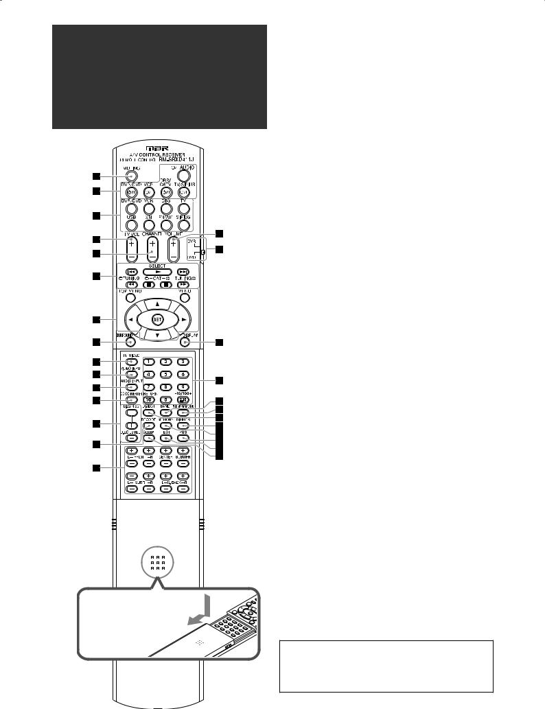
Parts identification
To open the cover of the remote control, push here then slide downward.
7 Remote control
See pages in parentheses for details.
1 MUTING button (22)
2Standby/on buttons (16, 20, 47 – 51)
 AUDIO, TV/SIRIUS
  , DBS/CATV
  , VCR
, VCR  , DVR/DVD
3Source selecting buttons (20, 24, 26, 47 – 51) TV, DBS, VCR, DVR/DVD, SIRIUS, FM/AM, XM, USB
4 TV VOL (volume) +/– button (47, 49)
5 CHANNEL +/– button (27, 47 – 51)
6• Operating buttons for video components (47 – 51)
4, 3, ¢, 1, 7, 8, ¡
•Operating buttons for FM/AM tuner (24) ( TUNING, TUNING 9
•Operating buttons for XM Satellite Radio or SIRIUS Satellite Radio (27, 47)
SELECT*, ( CAT, CAT 9
7Operating buttons for DVD recorder or DVD player** (48, 51)
TOP MENU, MENU, cursor buttons (3, 2, 5, ∞), SET
8 SURROUND button (44)
9 TV/VIDEO button (47, 49) p VIDEO INPUT button (21) q AUDIO INPUT button (21) w CC CONVERTER button (23)
eAdjusting buttons for Digital Equalizer (36) D.EQ FREQ, D.EQ LEVEL +/–
r DECODE button (22)
tAdjusting buttons for speaker and subwoofer output levels (36)
FRONT L +/–, FRONT R +/–, CENTER +/–, SUBWFR +/–, SURR L +/–, SURR R +/–, S.BACK L +/–, S.BACK R +/–
y VOLUME +/– button (21) u Mode selector (48, 51) i DISPLAY button (28, 47)
o• Numeric buttons (25, 27, 47 – 51) 1 – 10, 0, h10, +10/100+
• RETURN button (47)
; BAND* button (47)
a PREV*/FM MODE button (25 ,47) s DIRECT button (27)
d DIMMER button (22)
f MEMORY button (24, 27)
g PSS (Precise Surround Setup) button (17) h TEST button (18, 36)
j SLEEP button (23)
* For SIRIUS Satellite Radio only
**These buttons can be used for operating a DVD recorder (JVC products only) or DVD player, with the mode selector set to “DVR” or “DVD” (see page 48).
If these buttons do not function normally, use the remote control supplied with your DVD recorder or DVD player. Refer also to the manual supplied with the DVD recorder or DVD player for details.
•When operating a DVD recorder (for JVC products only), set the mode selector (u) to “DVR.”
•When operating a DVD player, set the mode selector (u) to “DVD.”
3
See pages in parentheses for details.
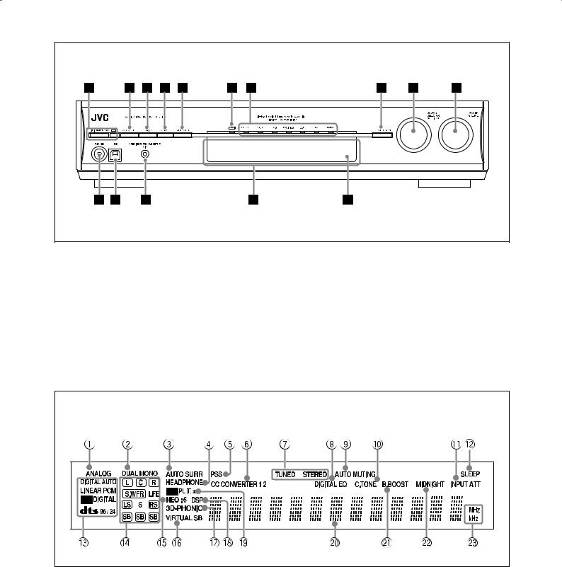
Front Panel |
1  STANDBY/ON button and standby lamp (16, 20)
2 CC CONVERTER button (23)
3 SETTING button (30)
4 ADJUST button (35)
5 SURROUND button (44)
6 HDMI lamp (9, 21)
7Source lamps
DVR/DVD, VCR, DBS, TV/SIRIUS, USB, XM, FM/AM
8• SET button (20, 30, 35)
• TUNER PRESET button (25, 28)
9• SOURCE SELECTOR (20, 25, 26)
• MULTI JOG (25, 28, 30, 35, 44)
p MASTER VOLUME control (21) q PHONES jack (21)
w USB terminal (15)
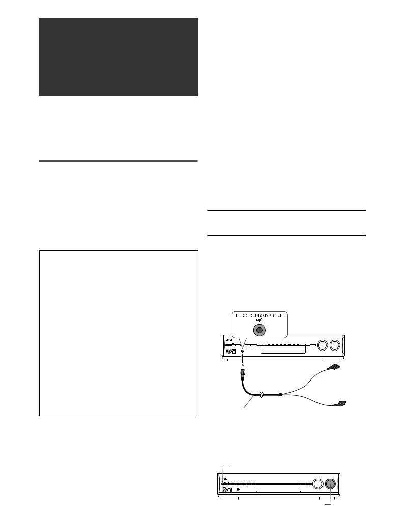
e PRECISE SURROUND SETUP MIC jack (16) r Display window (see below)
t Remote sensor (6)
Display window
1 ANALOG indicator (21)
2 DUAL MONO indicator (32)
3 AUTO SURR (surround) indicator (43)
4 HEADPHONE indicator (21, 42)
5 PSS (Precise Surround Setup) indicator (17)
6 CC CONVERTER 1 and CC CONVERTER 2 indicators (23)
7FM/AM tuner operation indicators (24) TUNED, STEREO
8 DIGITAL EQ indicator (36)
9 AUTO MUTING indicator (25)
0 C (center).TONE indicator (38)
- INPUT ATT (attenuate) indicator (37)
= SLEEP indicator (23)
~Digital signal format indicators (21, 22, 40, 41) DIGITAL AUTO, LINEAR PCM, 


 ,
,  ,
,  96/24
96/24
! Signal and speaker indicators (23)
@ NEO:6 indicator (40)
# VIRTUAL SB (surround back) indicator (43) $ 3D-PHONIC indicator (40, 41)
% DSP indicator (41)
^ 

 and
and 

 indicators (39 – 41) & Main display
* B (bass).BOOST indicator (37)
( MIDNIGHT indicator (33)
)Frequency unit indicators
MHz (for FM stations), kHz (for AM stations)
4
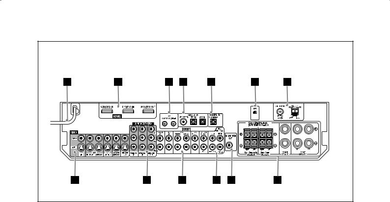
See pages in parentheses for details.
Rear Panel |
1 Power cord (14)
2HDMI terminals (9)
VCR(DBS) IN, DVR/DVD IN, MONITOR OUT
3 AV COMPU LINK-III terminals (45)
4DIGITAL IN terminals (14)
•Coaxial: 1(DVR/DVD)
•Optical: 2(DBS)
•Optical: 3(VCR)
5 DIGITAL OUT terminal (14)
6 XM jack (7)
7 FM/AM ANTENNA terminals (7)
8VIDEO jacks (10 – 13)
VIDEO (composite video) jacks, S-VIDEO jacks
•Input: DBS IN, VCR IN(PLAY), DVR/DVD IN(PLAY)
•Output: VCR OUT(REC), DVR OUT(REC), MONITOR OUT
9COMPONENT VIDEO (Y, PB, PR) jacks (10 – 13) VCR(DBS) IN, DVR/DVD IN, MONITOR OUT
pAUDIO jacks (10 – 13)
•Input: TV/SIRIUS IN, DBS IN, VCR IN(PLAY), DVR/DVD IN(PLAY)
•Output: VCR OUT(REC), DVR OUT(REC)
qDVD MULTI IN jacks (11)
CENTER, SUBWOOFER, SURR–L, SURR–R
w SUBWOOFER OUT jack (8)
eSpeaker terminals (8)
SURROUND BACK SPEAKERS, SURROUND SPEAKERS, CENTER SPEAKER, FRONT SPEAKERS
5
Getting started
Before installation
7 General precautions
•Be sure your hands are dry.
•Turn the power off to all components.
•Read the manuals supplied with the components you are going to connect.
7 Locations
•Install the receiver in a location that is level and protected from moisture and dust.
•The temperature around the receiver must be between –5 °C and 35 °C (23 °F and 95 °F).
•Make sure there is good ventilation around the receiver. Poor ventilation could cause overheating and damage the receiver.
•Leave sufficient distance between the receiver and the TV.
7 Handling the receiver
•Do not insert any metal object into the receiver.
•Do not disassemble the receiver or remove screws, covers, or cabinet.
•Do not expose the receiver to rain or moisture.
•Do not pull on the power cord to unplug the cord. When unplugging the cord, always grasp the plug so as not to damage the cord.
•When you are away on travel or otherwise for an extended period or time, remove the plug from the wall outlet. A small amount of power is always consumed while the power cord is connected to the wall outlet.
The receiver has a built-in cooling fan which operates while the receiver is turned on. Be sure to leave enough ventilation to obtain sufficient cooling effect.
CAUTION:
Do not connect the AC power cord until all other connections have been made.
Checking the supplied accessories
Check to be sure you have all of the following supplied accessories. If anything is missing, contact your dealer immediately.
•Remote control (× 1)
•Batteries (× 2)
•AM loop antenna (× 1)
•FM antenna (× 1)
•Dedicated earphone-type microphones (× 1)
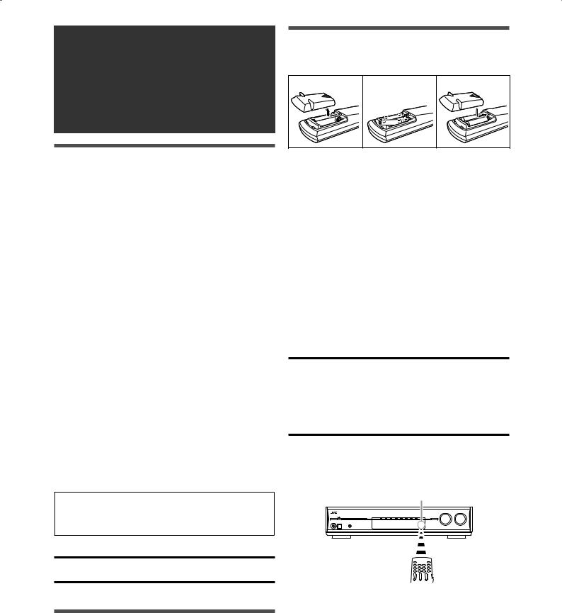
Putting the batteries in the remote control
1 |
2 |
3 |
Before using the remote control, put two supplied batteries first.
1Press and slide the battery cover on the back of the remote control.
2Insert the batteries.
Make sure to match the polarity: (+) to (+) and (–) to (–).
3 Replace the cover.
If the range or effectiveness of the remote control decreases, replace the batteries. Use two R6(SUM-3)/AA(15F) type dry-cell batteries.
•Supplied butteries are for initial setup. Replace for continued use.
CAUTION:
Follow these precautions to avoid leaking or cracking cells:
•Place batteries in the remote control so they match the polarity: (+) to (+) and (–) to (–).
•Use the correct type of batteries. Batteries that look similar may differ in voltage.
•Always replace both batteries at the same time.
•Do not expose batteries to heat or flame.
When using the remote control, aim the remote control directly at the remote sensor on the front panel.
Remote sensor
6
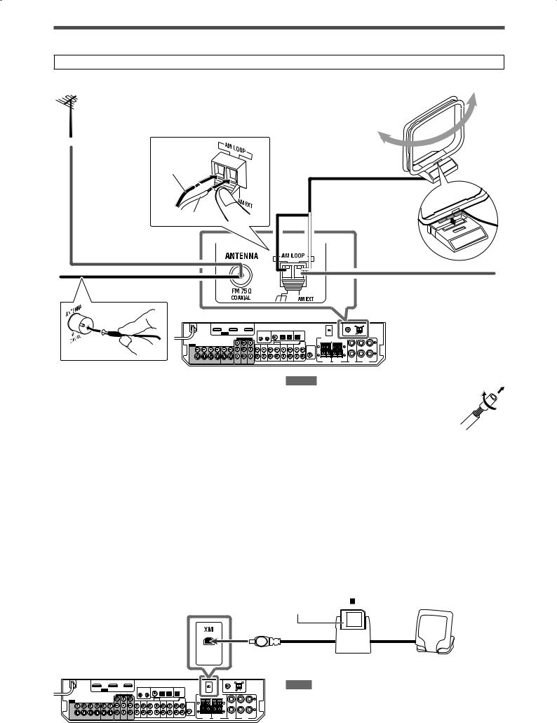
Connecting the antennas
Do not connect the AC power cord until all other connections have been made.
7 Connecting FM and AM antennas
If FM reception is poor, connect an outdoor FM antenna (not supplied).
Black
 White
White
AM loop antenna (supplied)
Snap the tabs on the loop into the slots of the base to assemble the AM loop antenna.
FM antenna (supplied) |
If AM reception is poor, connect an |
|
outdoor single vinyl-covered wire |
|
(not supplied). |
AM antenna connection
Connect the AM loop antenna (supplied) to the AM LOOP terminals: Connect the white cord to the AM EXT terminal, and connect the black cord to the H terminal.
Turn the loop until you have the best reception.
•If the reception is poor, connect an outdoor single vinylcovered wire (not supplied) to the AM EXT terminal. Keep the AM loop antenna connected.
FM antenna connection
Connect the supplied FM antenna to the FM 75 Ω COAXIAL terminal as a temporary measure.
Extend the supplied FM antenna horizontally.
•If the reception is poor, connect an outdoor FM antenna (not supplied). Before attaching a 75 Ω coaxial cable with a connector, disconnect the supplied FM antenna.
NOTES
•If the AM loop antenna wire is covered with vinyl, remove the vinyl while twisting it as shown on the right.
•Make sure the antenna conductors do not touch any other terminals, connecting cords and power cord. This could cause poor reception.
7 Connecting the XM Passport System (XM Passport and XM Passport Home Dock)*
To enjoy XM Satellite Radio, connect the XM Passport System (not supplied) to the receiver.
* You can also use the conventional XM Connect and Play Digital Antenna (not supplied) for the receiver.
XM Passport (not supplied)
XM Passport Home Dock (not supplied)
NOTE
For the best reception:
– Place the XM Passport Home Dock antenna near a south-facing window or where “Channel 1” can be heard clearly (see page 26).
– Make sure there is no obstruction between the XM Passport Home Dock antenna and the sky.
7
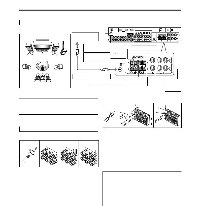
Connecting the speakers |
|
|
|
||
|
|
Do not connect the AC power cord until all other connections have been made. |
|
||
7 Speaker Layout Diagram |
|
|
|
||
|
|
|
Powered |
|
|
|
|
SW |
subwoofer (SW) |
|
|
|
|
|
Left surround back |
Center speaker (C) |
|
|
|
|
speaker (SBL)* |
|
|
|
|
|
|
|
|
FL |
C |
FR |
Right surround |
|
|
back speaker (SBR) |
|
|
|||
|
|
|
|
|
|
SL |
|
SR |
|
|
|
|
|
|
Right surround speaker (SR) |
Right front |
|
|
|
|
Left surround speaker (SL) |
Left front |
|
SBL |
(SB*) |
SBR |
speaker (R) |
||
|
|
speaker |
|||
|
|
|
|
|
(L) |
CAUTIONS: |
|
|
To connect the surround speakers and the surround back |
||
•Use speakers with the SPEAKER IMPEDANCE indicated by the speaker terminals (6 Ω – 16 Ω).
•DO NOT connect more than one speaker to one speaker terminal.
7 Connecting the speakers
Turn off all components before making connections.
To connect the center speaker and the front speakers
speakers |
|
|
1 |
2 |
3 |
1Cut, twist and remove the insulation at the end of each speaker cord.
1 |
2 |
3 |
4 |
2 Open the terminal (1), then insert the |
|
|
|
|
speaker cord (2). |
|
|
|
|
• For each speaker, connect the (+) and (–) terminals on |
|
|
|
|
the rear panel to the (+) and (–) terminals marked on the |
|
|
|
|
speakers. |
|
|
|
|
3 Close the terminal. |
1Cut, twist and remove the insulation at the end of each speaker cord.
2Turn the knob counterclockwise.
3Insert the speaker cord.
•For each speaker, connect the (+) and (–) terminals on the rear panel to the (+) and (–) terminals marked on the speakers.
*When using a single speaker for the surround back speaker
You can enjoy the surround sound by one surround back speaker. When using one surround back speaker,
–set “S BACK OUT” to “1SPK” (see page 31) and
–connect the surround back speaker to the left surround back speaker terminal. (No sound comes from the speaker if you connect it to the right surround back speaker terminal.)
4 Turn the knob clockwise. |
7 Connecting the powered subwoofer |
|
|
||
|
By connecting a subwoofer, you can enhance the bass or |
|
|
reproduce the original LFE signals recorded in digital software. |
|
|
Connect the input jack of a powered subwoofer to the |
|
|
SUBWOOFER OUT jack on the rear panel, using a cord with |
|
|
RCA pin plugs (not supplied). |
|
|
• Refer also to the manual supplied with your subwoofer. |
|
|
After connecting all the speakers and/or subwoofer, perform |
|
|
Precise Surround Setup to adjust the speaker settings |
|
|
automatically (see pages 16 to 19). |
|
|
|
|
|
NOTE |
|
|
You can place a subwoofer wherever you like since bass sound is non- |
|
|
directional. Normally place it in front of you. |
|
8
Connecting video components
Do not connect the AC power cord until all other connections have been made.
7 HDMI connection
IMPORTANT:
The HDMI video signals from the HDMI terminals are transmitted only through the HDMI MONITOR OUT terminal.
Therefore, you cannot view the playback picture on the TV:
–when the TV is connected to the receiver through the VIDEO jack (MONITOR OUT), S-VIDEO jack (MONITOR OUT), or COMPONENT VIDEO jacks (MONITOR OUT) and
–when a playing video component is connected to the receiver through the HDMI terminal—VCR(DBS) IN or DVR/DVD IN as well.
Turn off all components before making connections.
• When you connect the components, refer also to their manuals.  DVD recorder or DVD player
HDMI cables (not supplied)
TV
VCR (or DBS)
Converting video signals into HDMI signals
This receiver can convert composite video, S-video, and component video signals into HDMI signals and transmit the converted signals through the HDMI MONITOR OUT terminal. To use this function, you need to make the following procedure beforehand:
1 Connect your TV and this receiver with the HDMI cable. 2 Set the video output setting (see page 34) to “HDMI.”
3 Set the video input setting (see page 21) according to the connection method for each video component.
NOTES
•When playing back audio and video with the HDMI connection, the HDMI lamp on the front panel is lit.
•Select “HDMI” for the audio input setting (see page 21) when you enjoy sound with the HDMI connection.
•With input video signals converted into HDMI signals, the playback picture may be distorted when you change the playback mode (fastforward, rewind, or pause, for example).
•When connecting a VCR or DBS to the HDMI VCR(DBS) IN terminal, set the HDMI select setting (see page 34) correctly according to the equipment you connect. If you do not, you cannot view the playback picture on the TV.
•By using an HDMI-DVI conversion cable, you can connect the source components or the TV with DVI output. When connecting those components or TV, change the audio input setting to other than “HDMI.” (See page 21.)
•This receiver is compatible with standard video formats. If non-standard video formats are coming in, the picture may not appear properly on TV.
•The picture on the TV may not be the same aspect ratio as the ratio set on the source components.
•HDMI (High-Definition Multimedia Interface) is an interface which makes it possible to transmit digital audio and video signals with one cable. However, when connecting a TV to this receiver with an HDMI cable, the sound coming into this receiver is not transmitted to the speakers of the TV. You can enjoy sound only from the speakers connected to this receiver.
•When connecting a TV to the receiver with an HDMI cable, the following may cause noise or interrupt the sound and picture:
–Turning a source component on or off
–Changing the audio or video input setting of this receiver frequently
In this case, turn the receiver off, then turn it on again.
•When enjoying multi-channel PCM sound and selecting “HDMI” for the audio input setting (see page 21), some functions are not available. See page 11 for details.
•When you enjoy HDCP contents, sound and picture may not be transmitted to the speakers and TV for a few seconds in the beginning for confirmation.
9
7 Audio/video connection
In addition to the HDMI terminals, this receiver is equipped with three video terminals—composite video, S-video, and component video terminals, and two audio jacks—analog discrete 5.1 channel audio input jacks (DVD MULTI IN) and stereo audio jacks.
•If your video components have S-video (Y/C-separation) and/or component video (Y, PB, PR) jacks, connect them using an S-video cable (not supplied) or component video cable (not supplied). By using these terminals, you can get a better picture quality in the order:
Component > S-video > Composite
IMPORTANT:
The video signals from one type of these input jacks are transmitted only through the video output jacks of the same type. Therefore, if a recording video component and a playing video component are connected to the receiver through the video terminals of different type, you cannot record the picture. In addition, if the TV and a playing video component are connected to the receiver through the video terminals of different type, you cannot view the playback picture on the TV.*
DO NOT use a TV through a VCR or a TV with a built-in VCR; otherwise, the picture may be distorted.
CAUTION:
If you connect a sound-enhancing device such as a graphic equalizer between the source components and this receiver, the sound output through this receiver may be distorted.
If your video components have AV COMPU LINK terminals
See also page 45 for detailed information about the connection and the AV COMPU LINK remote control system.
*When connecting the TV to the receiver through the HDMI MONITOR OUT terminal and selecting “HDMI” for the video output setting, you can view the playback picture on the TV.
Do not connect the AC power cord until all other connections have been made.
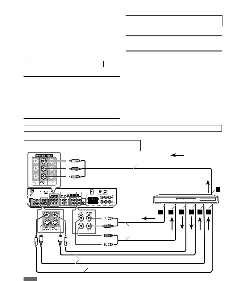
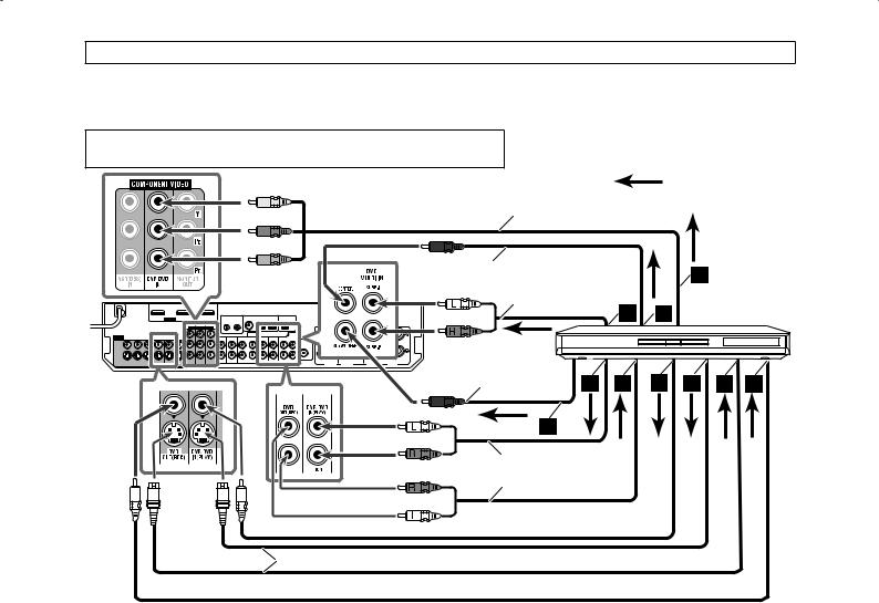
Connecting a DVD recorder or DVD player with its stereo output jacks:
Turn off all components before making connections.
• When you connect the components, refer also to their manuals.
Green |
: signal flow |
|
|
Blue |
Component video cable (not supplied) |
Red |
|
|
DVD recorder or DVD player |
White |
|
|
Red |
|
|
Red |
Stereo audio cable |
|
(not supplied) |
||
|
White
Composite video cable  (not supplied)
S-video cable (not supplied)
Composite video cable (not supplied)
NOTES
•Select the audio and video input setting according to the connection method. See page 21 for details.
•You can enjoy digital sound if using a digital coaxial or optical cable. When shipped from the factory, the digital coaxial terminal— DIGITAL IN 1(DVR/DVD) on the rear of the receiver is set for a DVD recorder and DVD player. For details of digital audio connection, see page 14.
ÅTo component video output
• Connect Y, PB, and PR correctly.
ı To left/right audio channel output
Ç Only for DVD recorder: To left/right audio channel input
Î To composite video output
‰ To S-video output
Ï Only for DVD recorder: To S-video input
Ì Only for DVD recorder: To composite video input
10
Do not connect the AC power cord until all other connections have been made.
Connecting a DVD recorder or DVD player with its analog discrete output jacks (DVD MULTI IN):
If your DVD recorder or DVD player has analog 5.1 channel output jacks, use the connection below. When a DVD-Audio disc is played back, the original high-quality multi-channel sounds can be reproduced by using this connection.
Turn off all components before making connections.
• When you connect the components, refer also to their manuals.
Green |
|
: signal flow |
|
|
|
||
Component video cable (not supplied) |
|
||
Blue |
|
|
|
Red |
|
|
|
Monaural audio cable (not supplied) |
|
||
White |
Stereo audio cable |
DVD recorder or |
|
|
(not supplied) |
||
Red |
DVD player |
||
|
|||
Monaural audio cable |
|
||
(not supplied) |
|
||
White |
|
|
|
Red |
|
|
|
Red |
Stereo audio cable |
|
|
(not supplied) |
|
||
White
Composite video cable  (not supplied)
S-video cable (not supplied)
 Composite video cable (not supplied)
Å To left/right surround channel audio output
ı To center channel audio output
ÇTo component video output
• Connect Y, PB, and PR correctly.
Î To subwoofer output
‰ To left/right front channel audio output
ÏOnly for DVD recorder: To left/right front channel audio input
Ì To composite video output
Ó To S-video output
È Only for DVD recorder: To S-video input
Ô Only for DVD recorder: To composite video input
|
|
|
|
When you enjoy the sound recorded in DVD-Audio... |
|
NOTES |
|
You can enjoy the sound recorded in DVD-Audio with either |
• When selecting “A MULTI” for the audio input setting and using |
||
analog or digital methods. |
|
the headphones, you can listen to the front channel sounds (left |
|
– With analog method: |
|
and right) only. The 3D HEADPHONE mode (see page 42) is not |
|
1.Connect your DVD recorder or DVD player to this |
|
available. |
|
receiver according to the diagram above. |
• When selecting “A MULTI” for the audio input setting or when |
||
2.Select “A MULTI” for the audio input setting. (See page |
|
multi-channel PCM signals (see page 41) are coming in with |
|
21.) |
|
selecting “HDMI” for the audio input setting, the following items |
|
|
are not available: |
||
– With digital method: |
|
||
|
– Precise Surround Setup (see pages 16 to 19) |
||
1.Connect your DVD recorder or DVD player and TV to this |
|
||
|
– Decode mode (see page 22) |
||
receiver with the HDMI cables. (See page 9.) |
|
||
|
– CC Converter (see page 23) |
||
2.Select “HDMI” for the audio input setting. (See page 21.) |
|
||
|
– EX/ES/PLllx (see page 32) |
||
|
|
– Dual Mono (see page 32) |
|
|
|
– Subwoofer output (see page 33) |
|
|
|
– Crossover frequency (see page 33) |
|
|
|
– Low frequency effect attenuator (see page 33) |
|
|
|
– Midnight mode (see page 33) |
|
|
|
– Digital equalization patterns (see page 36) |
|
|
|
– Bass Boost (see page 37) |
|
|
|
– Input attenuator mode (see page 37) |
|
|
|
– Sound parameters for Surround/DSP modes (see pages 37 and |
|
|
38) |
|
|
|
|
– Surround/DSP mode selection (see page 44) |
|
|
• The audio delay level setting (see page 34) does not take effect |
||
|
|
when selecting “A MULTI” for the audio input setting. |
|
|
• When you enjoy the sound recorded in DVD-Audio through the |
||
|
|
HDMI connection, use a DVD recorder or DVD player compatible |
|
|
|
with HDMI version 1.1. |
|
|
|
|
|
11
Do not connect the AC power cord until all other connections have been made.
Turn off all components before making connections.
• When you connect the components, refer also to their manuals.
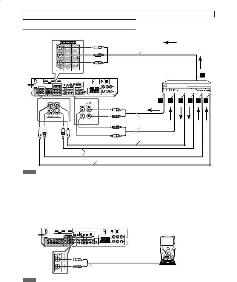
Connecting a VCR:
Green |
: signal flow |
|
|
Blue |
Component video cable (not supplied) |
|
Red |
|
|
VCR |
White |
|
Red |
|
Red |
Stereo audio cable |
(not supplied) |
|
White |
|
|
Composite video cable |
|
(not supplied) |
S-video cable (not supplied)
Composite video cable (not supplied)
NOTES
•Select the audio and video input settings according to the connection method. See page 21 for details.
•When connecting a VCR to the COMPONENT VIDEO jacks, select “VCR” for the COMPONENT select setting (see page 34); otherwise, the following occurs:
–You cannot view the playback picture on the TV.
–The AV COMPU LINK remote control system (see pages 45 and 46) cannot operate properly.
•You can enjoy digital audio if using a digital coaxial or optical cable. When shipped from the factory, the digital optical terminal—DIGITAL IN 3(VCR) on the rear of the receiver is set for a VCR. For details of the digital audio connection, see page 14.
ÅTo component video output
• Connect Y, PB, and PR correctly.
ı To left/right audio channel output
Ç To left/right audio channel input
Î To composite video output
‰ To S-video output
Ï To S-video input
Ì To composite video input
Connecting a SIRIUS Satellite Radio
White
Red
Stereo audio cable (not supplied) |
SIRIUS Satellite Radio |
NOTES
•To connect KT-SR2000 (JVC SIRIUS Satellite Radio) to this receiver, it is required to separately purchase KS-K6013 Home Docking Kit.
•You cannot use a digital audio cable (coaxial or optical) to connect a SIRIUS Satellite Radio to this receiver.
•After connecting a SIRIUS Satellite Radio to the TV/SIRIUS IN jacks, change the source name to “SIRIUS.” See page 20 for details.
12

Do not connect the AC power cord until all other connections have been made.
Turn off all components before making connections.
• When you connect the components, refer also to their manuals.
Connecting a DBS tuner: |
|
: signal flow |
Green |
Component video cable (not supplied) |
|
|
|
|
Blue |
White |
Stereo audio cable (not supplied) |
|
||
Red |
Red |
|
|
|
|
|
|
DBS tuner |
|
|
|
|
|
|
|
|
|
|
|
|
|
|
|
|
|
|
|
|
|
|
|
|
|
|
|
|
|
|
|
|
|
|
|
|
|
|
|
|
|
|
|
|
|
|
|
|
|
|
|
|
|
|
|
|
|
|
|
|
|
|
|
|
|
|
|
|
|
|
|
|
|
|
|
|
|
|
|
|
|
Composite video cable |
|
|
|
|
|
|
|
|
|
|
||
|
|
|
|
|
|
|
|
|
|
|
|
|
|
|
|
|
|
|
|
|
|
|
|
|
|
|
|
|
|
|
|
|
|
|
|
|
|
|
|
|
|
|
|
|||
|
|
|
|
|
|
|
|
|
|
|
|
|
|
|
|
|
|
|
|
|
|
|
|
|
|
|
|
|
|
|
|
|
|
|
|
|
|
|
|
|
|
|
|
|||
|
|
|
|
|
|
|
|
|
|
|
|
|
|
|
|
|
|
|
|
|
|
|
|
|
|
|
|
|
|
|
|
|
|
(not supplied) |
|
|
|
|
|
|
|
|
|
|
||
|
|
|
|
|
|
|
|
|
|
|
|
|
|
|
|
|
|
|
|
|
|
|
|
|
|
|
|
|
|
|
|
|
|
|
|
|
|
|
|
|
|
|
||||
|
|
|
|
|
|
|
|
|
|
|
|
|
|
|
|
|
|
|
|
|
|
|
|
|
|
|
|
|
|
|
|
|
|
|
|
S-video cable (not supplied) |
|
|
|
|
|
|
|
|
|
|
|
|
|
|
|
|
|
|
|
|
|
|
|
|
|
|
|
|
|
|
|
|
|
|
|
|
|
|
|
|
|
|
|
|
|
|
|
|
|
|
|
|
|
|
|
|
|
|
|
|
|
|
|
|
|
|
|
|
|
|
|
|
|
|
|
|
|
|
|
|
|
|
|
|
|
|
|
|
|
|
|
|
|
|
|
|
|
|
|
|
|
|
|
|
|
|
|
|
|
|
|
|
|
|
|
|
|
|
|
|
|
|
|
|
|
|
|
|
|
|
|
|
|
|
|
|
|
|
|
|
|
|
|
|
|
|
|
|
|
|
|
|
|
|
|
|
|
|
|
|
|
|
|
|
|
|
|
|
|
|
|
|
|
|
|
|
|
|
|
|
|
|
|
|
|
|
|
|
|
|
|
|
|
|
|
|
|
|
|
|
|
|
|
|
|
|
|
|
|
|
|
|
|
|
|
|
|
|
|
|
|
|
|
|
|
|
|
|
|
|
|
|
|
|
|
|
|
|
|
|
|
|
|
|
|
|
|
|
|
|
|
|
|
|
|
|
|
|
|
|
|
|
|
|
|
|
|
|
|
|
|
|
|
|
|
|
|
|
|
|
|
|
|
|
|
|
|
|
|
|
|
|
|
|
|
|
|
|
|
|
|
|
|
|
|
|
|
|
|
|
|||||||||||||||||||||||||||||
NOTES |
Å To left/right audio channel |
|
||||||||||||||||||||||||||||||||||||||||||||
|
|
|||||||||||||||||||||||||||||||||||||||||||||
• Select the audio and video input setting according to the connection method. See page 21 for |
output |
|
||||||||||||||||||||||||||||||||||||||||||||
details. |
ı To component video output |
|
||||||||||||||||||||||||||||||||||||||||||||
• When connecting a DBS tuner to the COMPONENT VIDEO jacks, select “DBS” for the COMPONENT |
• Connect Y, PB, and PR |
|
||||||||||||||||||||||||||||||||||||||||||||
select setting (see page 34); otherwise, you cannot view the playback picture on the TV. |
|
|||||||||||||||||||||||||||||||||||||||||||||
|
|
|
correctly. |
|
||||||||||||||||||||||||||||||||||||||||||
• You can enjoy digital sound if using a digital coaxial or optical cable. When shipped from the |
|
|
|
|
||||||||||||||||||||||||||||||||||||||||||
Ç To composite video output |
|
|||||||||||||||||||||||||||||||||||||||||||||
factory, the digital optical terminal—DIGITAL IN 2(DBS) on the rear of the receiver is set for a DBS |
|
|||||||||||||||||||||||||||||||||||||||||||||
tuner. For details of digital audio connection, see page 14. |
Î To S-video output |
|
||||||||||||||||||||||||||||||||||||||||||||
Connecting a TV:
Connect the TV to the appropriate MONITOR OUT jacks to view the playback picture from any other connected video components.
: signal flow
Green


 Component video cable (not supplied)
  Blue
Blue
Red
TV
White |
Stereo audio cable |
|
(not supplied) |
||
|
||
Red |
|
S-video cable (not supplied)
 Composite video cable (not supplied)
NOTES
•Select the audio input setting according to the connection method. See page 21 for details.
•You can enjoy digital sound if using a digital coaxial or optical cable. For details of the digital audio connection, see page 14.
•Select “OTHER” for the video output setting (see page 34).
ÅTo component video input
• Connect Y, PB, and PR correctly.
ı To left/right audio channel output
Ç To S-video input
Î To composite video input
13
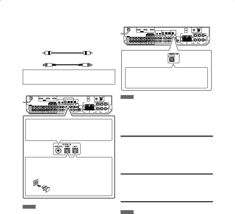
7 Digital audio connection
This receiver is equipped with three DIGITAL IN terminals— one digital coaxial terminal and two digital optical terminals— and one DIGITAL OUT terminal.
To reproduce the digital sound, use the digital audio connection in addition to the analog audio connection methods described on pages 10 to 13.
Digital coaxial cable (not supplied)
Digital optical cable (not supplied)
Turn off all components before making connections.
•When you connect the components, refer also to their manuals.
Digital input terminals:
When the component has a digital coaxial output terminal, connect it to the 1(DVR/DVD) terminal, using a digital coaxial cable (not supplied).
Digital output terminal:
You can connect any digital components which have an optical digital input terminal.
Connecting digital recording equipment to the DIGITAL OUT terminal enables you to perform digital-to-digital recording.
NOTES
•The digital signal format transmitted through the DIGITAL OUT terminal is the same as that of the input signal. For example, when the DTS signals are input, the DTS signals are transmitted.
•The digital signal coming through the USB terminal, HDMI input terminal and XM jack cannot be output from the DIGITAL OUT terminal.
When the component has a digital optical output terminal, connect it to the 2(DBS) or 3(VCR) terminal, using a digital optical cable (not supplied).
Before connecting a digital optical cable, unplug the protective plug.
NOTES
•When shipped from the factory, the DIGITAL IN terminals have been set for use with the following components:
–1(DVR/DVD): For DVD recorder or DVD player
–2(DBS): For DBS tuner
–3(VCR): For VCR
If you connect the components, change the digital input (DIGITAL IN) terminal setting correctly. See “Setting the digital input (DIGITAL IN) terminals—DIGITAL IN 1/2/3” on page 34.
• Select “DIGITAL” for the audio input setting (see page 21).
Connecting the power cord
When all the audio/video connections have been made, connect the AC power plug to the wall outlet. Make sure that the plugs are inserted firmly.
• The standby lamp lights in red.
CAUTIONS:
•Do not touch the power cord with wet hands.
•Do not alter, twist or pull the power cord, or put anything heavy on it, which may cause fire, electric shock, or other accidents.
•If the cord is damaged, consult a dealer and have the power cord replaced with a new one.
NOTES
•Keep the power cord away from the connecting cables and the antennas. The power cord may cause noise or screen interference.
•The preset settings such as preset channels and sound adjustment may be erased in a few days in the following cases:
–When you unplug the power cord.
–When a power failure occurs.
•When you unplug the power cord with the receiver on and connect the power cord again, the receiver enters standby mode.
14
USB connection
This receiver is equipped with a USB terminal on the front panel. You can connect your PC to this terminal and enjoy sound reproduced through your PC.
When you connect your PC for the first time, follow the procedure below.
•Remember you cannot send any signal or data to your PC from this receiver.
IMPORTANT:
Check if your PC equipped with the CD-ROM drive is running on Windows® 98 SE*, Windows® Me*, Windows® 2000*, or Windows® XP* and prepare its CD-ROM.
7 How to install the USB drivers
The following procedure is described using the English version of Windows® XP*. If your PC is running on a different version or language of operating system, the windows shown on your PC monitor will differ from the ones used in the following procedure.
See pages 20 and 21 for the operations of the receiver.
1Turn on your PC.
•If the PC has been turned on, quit all the applications now running.
2Turn on the receiver, and select the source as “USB.”
3Set the volume to minimum.
IMPORTANT:
Always set the volume to “0” when connecting or disconnecting the other equipment.
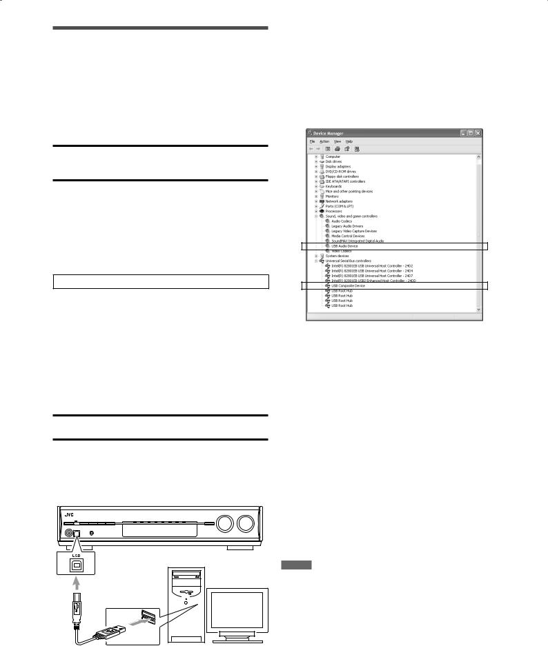
4Connect the receiver to the PC using a USB cable (not supplied).
•Use “USB series A plug to B plug” cable when connecting.
PC
USB cable (not supplied)
The USB drivers are installed automatically.
•If the USB drivers are not installed automatically, install the USB drivers by following the instructions on the PC monitor.
5Check if the drivers are correctly installed.
1.Open the Control Panel on your PC:
Select [Start] = [Control Panel].
2.Select [System] = [Hardware] = [Device Manager] = [Sound, video and game controllers] and [Universal Serial Bus controllers].
•The following window appears, and you can check if the drivers are installed.
Now your PC is ready for playback through the USB connection.
After installation is completed, you can use your PC as the playback source. The PC automatically recognizes the receiver whenever the receiver is connected by a USB cable and turned on.
•When not using the PC as the playback source, disconnect the USB cable from the receiver.
To play back sounds on the PC, refer to the manual supplied with the sound reproduction application installed in the PC.
If no sound comes from the speakers, check the following:
–Select “USB” as the source.
–Connect the USB cable correctly.
–Check the receiver is recognized by the PC properly (see above).
–Check the playback software is compatible with the PC.
–Open the Control Panel on your PC, select [Sounds and Audio Devices] = [Audio] tab = [Sound playback] = [Default device], and check [Default device] is set to [USB Audio DAC].
NOTES
•DO NOT turn off the receiver or disconnect the USB cable while installing the drivers and while your PC is recognizing the receiver.
•Use a USB cable (version 1.1 or later). Recommended cord length is less than 1.5 m.
•If your PC does not recognize the receiver, disconnect the USB cable and connect it again. If it does not work yet, restart Windows®*.
•The installed drivers can be recognized only when the USB cable is connected between the receiver and your PC.
•The sound may not be played back correctly—interrupted or degraded—due to your PC settings and PC specifications.
*Microsoft®, Windows® 98 SE, Windows® Me, Windows® 2000, and Windows® XP are registered trademarks of Microsoft corporation.
15
Precise Surround
Setup
By using Precise Surround Setup, you can optimize the speaker settings easily, quickly and systematically without troublesome adjustments.
To obtain the best possible sound effect from the Surround/ DSP modes, set up the speaker and subwoofer information after all the connections are completed.
Setting the speakers automatically
Precise Surround Setup detects the sound from the speakers to measure your listening environment with dedicated earphone-type microphones (supplied), and automatically adjusts the following in less than 1 minute:
•Speaker size*
•Speaker distance*
•Speaker output level*
•Crossover frequency*
•Frequency response
The receiver generates test tones from each speaker and picks them up with dedicated earphone-type microphones.
The microphones feedback the test tones to the receiver.
*You can also adjust the settings manually. (See pages 29 to 31, and 33.)
7 Before starting Precise Surround Setup
•Connect all of your speakers and subwoofer correctly and confirm their position.
•When subwoofer has a built-in volume and crossover frequency controls, adjust them as follows:
–Set the volume level to the medium.
–Set the crossover frequency to the highest level.
•Precise Surround Setup is not available in the following cases:
–While headphones are connected
–When selecting “A MULTI” for the audio input setting (see page 11)
–When multi-channel PCM signals (see page 41) are coming in with selecting “HDMI” for the audio input setting (see page 11)
•Do not block between the earphone-type microphones and speakers while the microphones are picking up test tones from the speakers.
•If the microphone cord is not long enough to make a connection between the receiver and your listening position, use a stereo extension cord (not supplied).
–You cannot get correct results with a monaural extension cord.
CAUTION:
Be sure that loud test tones will be generated from speakers during Precise Surround Setup.
• The volume of test tones is not adjustable.
7 Operating procedure
1Plug the dedicated earphone-type microphones into the PRECISE SURROUND SETUP MIC jack.
•Keep the connection until Precise Surround Setup is completed.
Dedicated earphone-type microphones (supplied)
2Press  STANDBY/ON (or
  AUDIO on the remote control) to turn the power on.
•Set the volume level to the medium or lower turning the MASTER VOLUME control (see page 21).
 STANDBY/ON button
MASTER VOLUME control
16
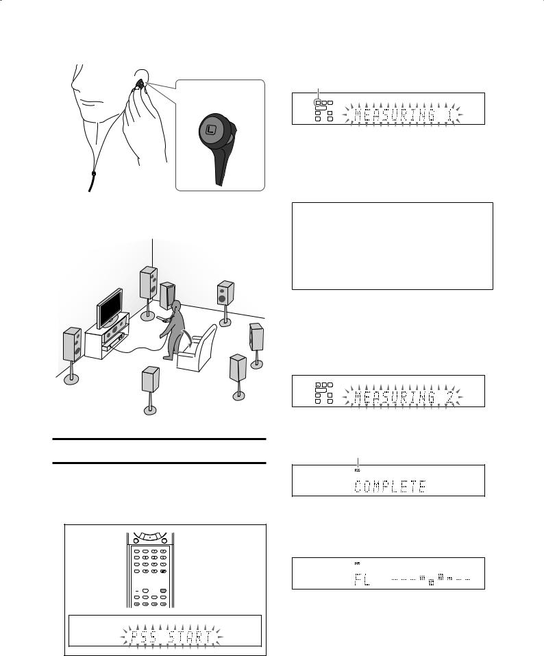
3Put on the microphones.
•Insert the microphone with “L” into your left ear, the microphone with “R” your right ear.
Example:
Microphone with “L”
4Take your usual listening position with the microphones and the remote control.
CAUTION:
Keep quiet so that Precise Surround Setup can detect test tones properly.
Precise Surround Setup starts detecting the speaker and subwoofer information.
•When starting Precise Surround Setup, the muting mode and Dimmer are automatically canceled.
•“MEASURING 1” flashes on the display.
Current speaker*1
*1 When the current speaker is the right or left surround back speaker, two surround back speaker indicators ( ) light up at a time.
A test tone comes out of each speaker in the following order, then the microphones pick up the test tones and feedback it to the receiver:
FL (Left front speaker) = C (Center speaker) = FR (Right front speaker) = SR (Right surround speaker)
=SBR (Right surround back speaker)*2 = SBL (Left surround back speaker)*2 = SL (Left surround speaker)
=SW (Subwoofer)
*2 When using a single speaker for the surround back speaker, the test tone comes out of “SB (Surround back speaker)” instead of “SBR” and “SBL.”
•Do not touch the microphones while the microphones are picking up the test tones.
‘
The receiver generates test tones again.
Precise Surround Setup starts detecting, adjusts the sound output level from each speaker, and corrects the frequency response of each speaker.
• “MEASURING 2” flashes on the display.
‘
When Precise Surround Setup is completed, “COMPLETE” appears and the PSS indicator lights up on the display.
PSS indicator
5Press and hold PSS on the remote control for about 4 seconds until “PSS START” starts flashing on the display.
 PSS
PSS
•If Precise Surround Setup is not completed properly...
An error message will appear on the display. In such a case, see “Troubleshooting for Precise Surround Setup“ on page 19.
‘
An optimized test tone comes out of each speaker so that you can confirm the results of Precise Surround Setup, and the corrected frequency response of each speaker appears on the display at the same time.
•See “Checking the frequency responses corrected by Precise Surround Setup” on page 18 about the frequency responses on the display.
‘
The receiver automatically returns to the normal operation mode after all the test tones have been output from the speakers.
Continued on the next page
17
6Unplug the earphone-type microphones.
•When unplugging the microphones, pull on the plug, not the cord itself.
NOTES
•Do not press any buttons on the remote control or the front panel of the receiver during Precise Surround Setup; otherwise, the receiver stops setting and returns to the normal operation mode.
–After “COMPLETE” is displayed, the Precise Surround Setup results are applied to the speaker settings.
•The speaker size measured by Precise Surround Setup may be different from that of the manual setting recommendation (see page 30). Precise Surround Setup measures the speaker size not only by the cone speaker size but also by the other speaker features.
•There may be a case that the receiver fails to detect subwoofer and does not activate it (no optimized test tone comes out of the subwoofer).
In such a case, set the volume level of the subwoofer higher and perform Precise Surround Setup again.
•When you change your listening environment, such as speakers, speaker position, your listening position or so, perform Precise Surround Setup again to optimize the speaker settings.
•Depending on the listening environment, Precise Surround Setup may not measure the speaker settings accurately. In such a case, adjust the settings manually. See pages 29 to 31, and 33.
•The supplied earphone-type microphones cannot be used as headphones.
•When the AV COMPU LINK remote control system works during Precise Surround Setup, this receiver stops setting and returns to the normal operation mode.
7 Turning the frequency optimizing function off
7 Checking the frequency responses corrected by Precise Surround Setup
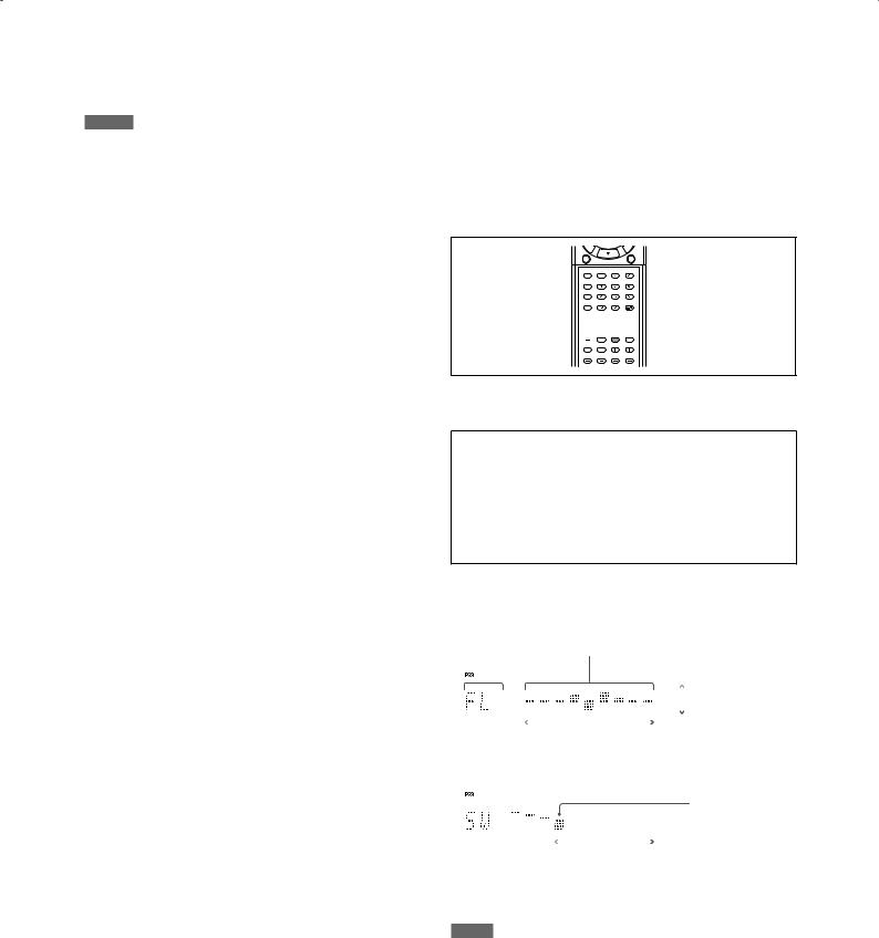
You can check the current settings of the frequency responses with test tones from speakers and the indications on the display when the frequency optimizing function is activated.
From the remote control ONLY:
1Press TEST to check the frequency response of each speaker on the display.
 TEST
TEST
•A test tone also comes from each speaker in the following order:
FL (Left front speaker) = C (Center speaker) = FR (Right front speaker) = SR (Right surround speaker) = SBR (Right surround back speaker)* = SBL (Left surround back speaker)* = SL (Left surround speaker) = SW (Subwoofer) * When using a single speaker for the surround back
speaker, the test tone comes out of “SB (Surround back speaker)” instead of “SBR” and “SBL.”
After performing Precise Surround Setup, the receiver |
• The frequency response of each speaker appears on the |
||||||||||||
optimizes the frequency response for each speaker. |
display as follows: |
|
|
|
|
|
|
||||||
You can turn the frequency optimizing function off. |
EX. 1: When a test tone comes from the left front speaker |
||||||||||||
|
|
||||||||||||
Press PSS to turn the frequency optimizing |
Current speaker |
|
Frequency response |
||||||||||
|
|
|
|
|
|
|
|
|
|
|
|||
|
|
|
|
|
|
|
|
|
|
|
|||
function off. |
|
|
|
|
|
|
|
|
|
+ 9 dB |
|||
|
|
|
|
|
|
|
|
|
|||||
• Each time you press the button, the frequency optimizing |
|
|
|
|
|
|
|
|
|
|
Optimizing level |
||
|
|
|
|
|
|
|
|
|
|
||||
function alternates between on and off. |
|
|
|
|
|
|
|
|
|
|
|||
|
|
|
|
|
|
|
|
|
– 9 dB |
||||
When the function is activated, the PSS indicator is lit. |
|
|
|
|
|
|
|
|
|
||||
|
|
|
|
|
|
|
|
|
|||||
|
|
Low |
Frequency |
High |
|||||||||
|
|
|
|
||||||||||
|
|
|
|
|
|
|
|
|
|
|
|
|
|
NOTE |
EX. 2: When a test tone comes from the subwoofer |
||||||||||||
This function is not available: |
|||||||||||||
|
|
|
|
|
|
|
|
|
|
|
|||
– Until Precise Surround Setup has been completed at least once; |
|
|
|
|
|
|
|
|
|
|
Crossover |
||
otherwise, “NO PSS” appears on the display. |
|
|
|
|
|
|
|
|
|
|
|||
|
|
|
|
|
|
|
|
|
|
frequency |
|||
– When selecting “A MULTI” for the audio input setting (see page 11). |
|
|
|
|
|
|
|
|
|
|
|||
– When multi-channel PCM signals (see page 41) are coming in with |
|
|
|
|
|
|
|
|
|
|
|
||
selecting “HDMI” for the audio input setting (see page 11). |
|
|
|
|
|
|
|
|
|
|
|
||
|
|
|
80 Hz |
|
200 Hz |
||||||||
|
|
|
|
|
|
||||||||
2 Press TEST again to stop the test tone.
NOTE
While the PSS indicator is off, pressing TEST generates test tones without showing frequency responses. See page 36.
18
Troubleshooting for Precise Surround Setup
When problems occur, a message appears on the display during Precise Surround Setup. In this case, refer to the following solution, then perform Precise Surround Setup again.
• To restart Precise Surround Setup, press PSS on the remote control; however, when you have turned the receiver off for the
Error message |
Possible cause |
Solution |
|
Headphones are connected to the PHONES jack. |
Unplug the headphones. |
|
The dedicated earphone-type microphones are |
Plug the microphones into the PRECISE SURROUND |
|
not connected correctly. |
SETUP MIC jack on the front panel firmly. |
|
There is some background noise. |
• Restart in a quiet environment. |
|
|
• If some electronic equipment is used near the |
|
|
listening position, turn off the equipment such as |
|
|
air conditioners, etc. |
|
The speaker is too close to the listening position. |
Place the speakers farther from the listening position. |
|
• Any of the front speakers is not connected or its |
• Check the left and right front speakers connections. |
|
connection is loose. |
|
|
• The microphone connection is loose. |
• Plug the microphones into the PRECISE SURROUND |
|
|
SETUP MIC jack on the front panel firmly. |
|
The built-in volume control of the powered |
Set the volume level of the subwoofer lower. |
|
subwoofer is set to too high. |
|
* |
The speaker is too far from the listening position |
Adjust the speaker position and angle. |
|
or the speaker angle is inappropriate. |
|
* |
The speaker is too far from the listening position. |
The speaker distance is adjustable up to 9 m (30 ft). |
|
|
Place the speaker within the adjustable range from |
|
|
the listening position. |
* |
• When the size of the front speakers is small, no |
• Check the connection of the subwoofer and turn it |
|
subwoofer is detected. |
on, or replace the front speakers with larger ones. |
|
• The receiver might have failed to detect |
• Set the volume level of the subwoofer higher. |
|
subwoofer. |
|
* |
The front speakers are smaller than the surround |
• Change the front speakers with the larger ones |
|
speakers. |
than the surround speakers. |
|
|
• Change the surround speakers with the smaller |
|
|
ones than the front speakers. |
* |
The surround speakers are smaller than the |
• Change the surround speakers with the larger ones |
|
surround back speakers. |
than the surround back speakers. |
|
|
• Change the surround back speakers with the |
|
|
smaller ones than the surround speakers. |
* |
The right-and-left front speaker size is |
Rearrange the front speakers as their size is |
|
unproportioned. |
proportioned. |
* |
• Any of the surround speakers is not connected |
• Check the connection of the surround speakers. |
|
or its connection is loose. |
|
|
• The right-and-left surround speaker size is |
• Rearrange the surround speakers as their size is |
|
unproportioned. |
proportioned. |
* |
• The left surround back speaker is not connected |
• Check the connection of the left surround back |
|
or its connection is loose even though the right |
speaker. |
|
surround back speaker is detected. |
• When using a single speaker as the surround |
|
|
back speaker, connect it to the left surround back |
|
|
speaker terminal (see page 8). |
|
• The right-and-left surround back speaker size is |
• Rearrange the surround back speakers as their size |
|
unproportioned. |
is proportioned. |
Warning message |
Possible cause |
Solution |
* |
The polarity of the speaker connection is wrong. |
Match the polarity of the speaker terminals (see page |
|
|
8). |
* The signal indicator of the corresponding speaker lights up with the error/warning message.
NOTES
•Before making speaker connections, turn the receiver off and unplug the power cord.
•If you press the source selecting button for the current source on the remote control while an error message is displayed, the receiver cancels Precise Surround Setup and returns to the normal operation mode.
•If multiple errors are detected during Precise Surround Setup, only the most serious error will be shown on the display.
•The warning message is displayed for about 10 seconds and the receiver automatically returns to Precise Surround Setup.
•Depending on the speaker performance or the listening position, there may be a case that the warning message appears even though speaker connections are correct. In such a case, there is no effect on the results of Precise Surround Setup.
19
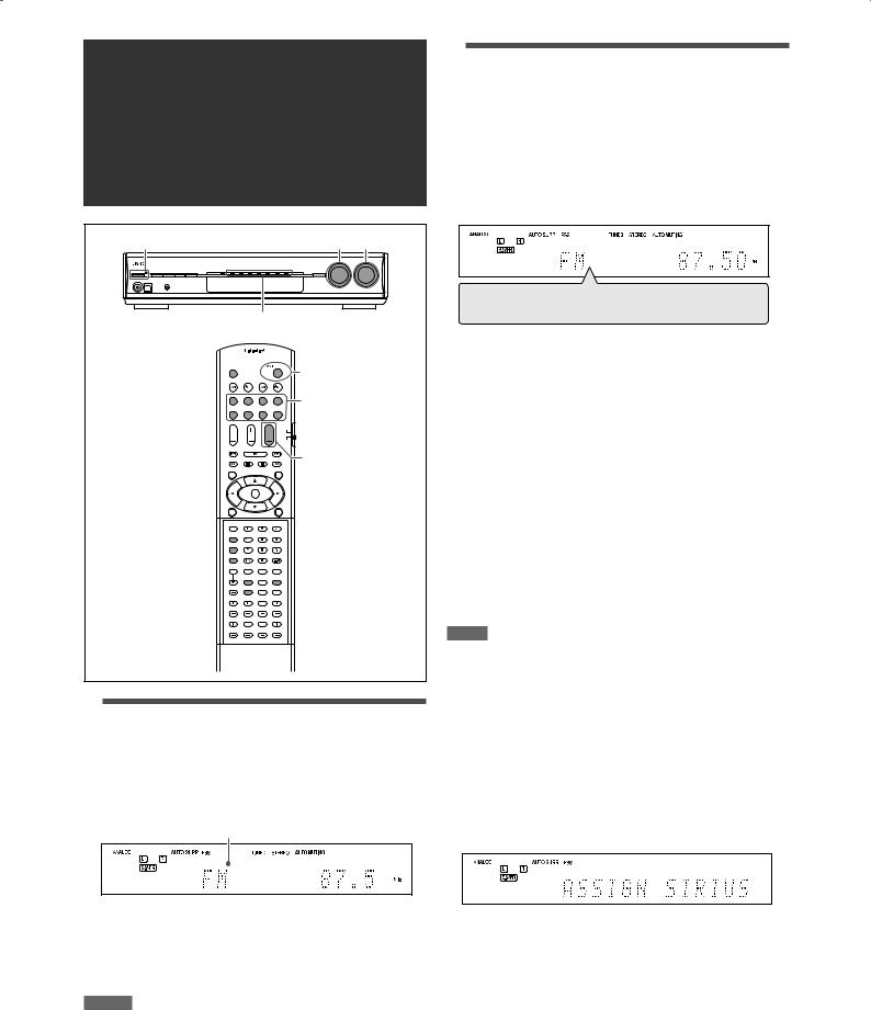
Basic operations
1 |
2 |
3 |
|
Source lamps |
|
|
1 |
|
|
2 |
|
|
3 |
|
1Turn on the power
Press  STANDBY/ON (or
  AUDIO on the remote control).
The standby lamp goes off and the current source lamp lights in red.
Current source name appears.
To turn off the power (into standby):
Press  STANDBY/ON (or
  AUDIO on the remote control) again.
The standby lamp lights in red.
NOTES
•A small amount of power is consumed in standby mode. To turn the power off completely, unplug the AC power cord.
•Turning a source component on before turning the receiver on may cause a noise or interrupt the sound and picture. In this case, turn both the source component and the receiver off, then turn the receiver on before turning the source component on.
2Select the source to play
On the front panel:
Turn SOURCE SELECTOR until the source name you want appears on the display.
The source lamp corresponding to the selected source lights in red.
•As you turn SOURCE SELECTOR, the source changes as follows:
DVR/DVD Ô VCR Ô DBS Ô TV(SIRIUS)* Ô USB Ô XM Ô FM Ô AM Ô (Back to the beginning)
DVR/DVD: |
Select this for the DVD recorder or DVD player. |
VCR: |
Select this for the VCR. |
DBS: |
Select this for the DBS tuner. |
TV*: |
Select this for the TV. |
SIRIUS*: |
Select this for the SIRIUS Satellite Radio. |
USB: |
Select this for the PC component. |
XM: |
Select this for the XM Satellite Radio. |
FM: |
Select this for the FM broadcast. |
AM: |
Select this for the AM broadcast. |
From the remote control:
Press one of the source selecting buttons.
•For “FM” and “AM,” press FM/AM.
Each time you press the button, the band alternates between “FM” and “AM.”
NOTE
When you connect a VCR or DBS to the HDMI VCR(DBS) IN terminal or COMPONENT VIDEO jacks on the rear of the receiver, you need to select either “VCR” or “DBS” for each terminal according to the component you connect (see page 34).
* Changing the source name of TV/SIRIUS input
On the front panel ONLY:
Press SET when “TV” is selected as the source.
•“ASSIGN SIRIUS” appears on the display for a while.
•To change the source name to “TV,” press SET when “SIRIUS” is selected as the source. “ASSIGN TV” appears on the display for a while.
20
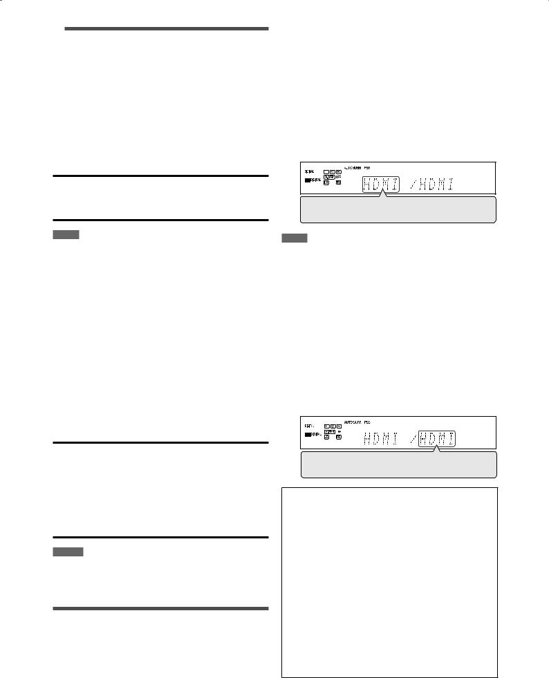
3Adjust the volume
To increase the volume, turn MASTER VOLUME control clockwise (or press VOLUME + on the remote control).
To decrease the volume, turn MASTER VOLUME control counterclockwise (or press VOLUME – on the remote control).
•When you adjust the volume, the volume level indication appears on the display for a while.
CAUTION:
Always set the volume to the minimum before starting any sources. If the volume is set at its high level, the sudden blast of sound energy can permanently damage your hearing and/ or ruin your speakers.
NOTE
The volume level can be adjusted within the range between “0” (minimum) and “50” (maximum).
7 Selecting the video input setting
From the remote control ONLY:
1Press one of the source selecting buttons to select the source you want.
2Press VIDEO INPUT to select the video input setting.
•Each time you press the button, the input setting changes as follows. This setting is memorized for each source.
HDMI = CMPNT (Component) = S (S-Video) = C (Composite) = (Back to the beginning)
NOTE
For “VCR” and “DBS,” set the HDMI select and COMPONENT select settings correctly if necessary (see page 34).
7 Listening with headphones
You can enjoy not only stereo software but also multi-channel software through the headphones. (Sounds are down-mixed to the front channels while playing multi-channel software.)
Connect a pair of headphones to the PHONES jack on the front panel to activate the HEADPHONE mode.
The HEADPHONE indicator lights up on the display.
•You can also enjoy the Surround/DSP mode through the headphones—3D HEADPHONE mode (see page 42).
•Disconnecting a pair of headphones from the PHONES jack cancels the HEADPHONE (or 3D HEADPHONE) mode and activates the speakers.
CAUTIONS:
•Be sure to turn down the volume:
–Before connecting or putting on headphones, as high volume can damage both the headphones and your hearing.
–Before removing headphones, as high volume may output from the speakers.
•Do not plug headphones into the PRECISE SURROUND SETUP MIC jack; otherwise, loud tones may come out of the headphones.
NOTES
•When using the headphones, the speaker settings does not take effect temporarily.
•The supplied earphone-type microphones cannot be used as headphones.
Selecting the video and audio input settings
You need to select the proper video and audio input settings for each source according to the connection methods on pages 9 to 14.
•In case of digital audio connection using the DIGITAL IN terminals on the rear of the receiver, you also need to select the correct digital input terminal (see page 34).
•Once you have made an adjustment, it is memorized for each source.
7 Selecting the audio input setting
From the remote control ONLY:
1Press one of the source selecting buttons to select the source you want.
2Press AUDIO INPUT to select the audio input setting.
•Each time you press the button, the audio input setting changes as follows. This setting is memorized for each source.
HDMI = DIGITAL = ANALOG = A MULTI = (Back to the beginning)
HDMI (for “DVR/DVD,” “VCR” and “DBS”):
Select for the source with HDMI connection. The receiver automatically detects the incoming signal format, then the digital signal format indicator (LINEAR PCM, 


 ,
,  , or
, or  96/24) for the detected signal lights up, and the HDMI lamp on the front panel lights up.
DIGITAL*: Select for the digital input setting. The receiver automatically detects the incoming signal format, then the digital signal format indicator (LINEAR PCM, 


 ,
,  , or
, or  96/24) for the detected signal lights up.
ANALOG*: Select for the analog input setting. The ANALOG indicator lights up on the display.
A MULTI (Only for “DVR/DVD”):
Select when connecting a DVD recorder or DVD player to DVD MULTI IN jacks (see page 11). The ANALOG indicator lights up on the display.
*When “TV” is selected as the source, only “DIGITAL” and “ANALOG” are available.
Continued on the next page
21
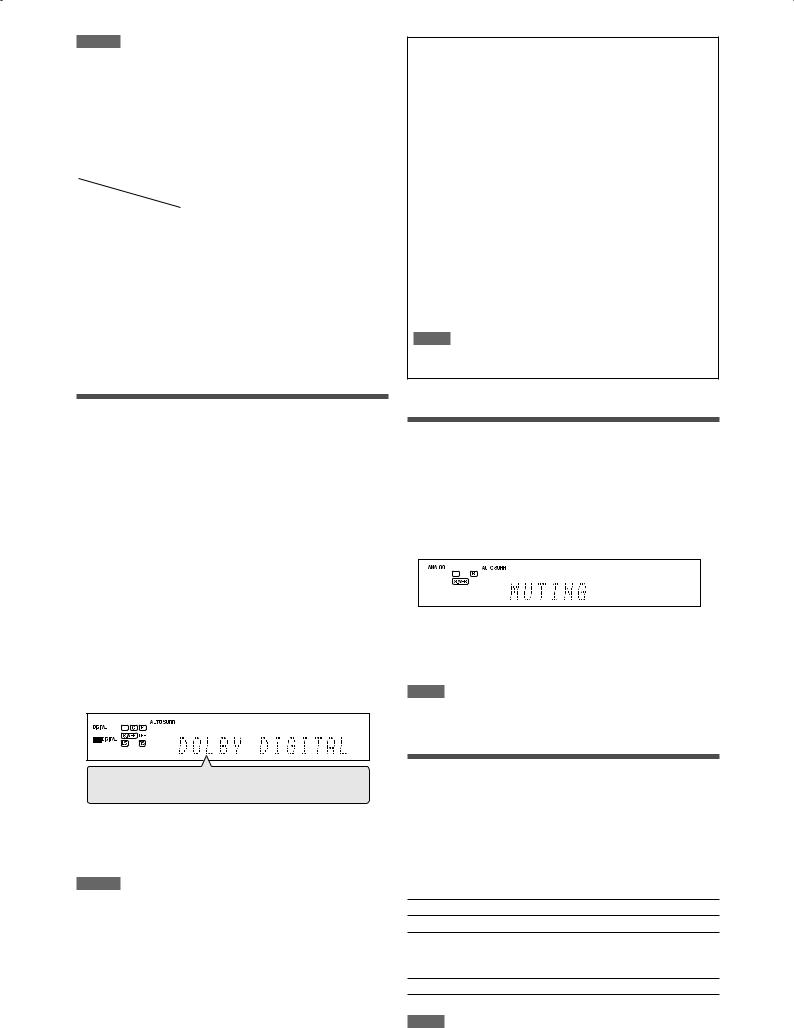
NOTES
•“HDMI” is selectable only when the video input setting is also to “HDMI” (see page 21).
The audio input setting may automatically change if you change the video input setting to or from “HDMI.” In such a case, make sure that the appropriate setting is selected.
•“DIGITAL” is available for the source which is assigned for “DIGITAL IN 1,” “DIGITAL IN 2,” or “DIGITAL IN 3.” See page 34 for details.
Initial setting of the video and audio input for each source:
Setting |
Video input |
Audio input |
|
Source |
|||
|
|
||
DVR/DVD |
HDMI |
HDMI |
|
VCR |
HDMI |
HDMI |
|
DBS |
S |
DIGITAL |
|
TV |
— |
ANALOG |
|
SIRIUS |
— |
ANALOG (fixed) |
|
USB |
— |
DIGITAL (fixed) |
|
XM |
— |
DIGITAL (fixed) |
|
FM |
— |
ANALOG (fixed) |
|
AM |
— |
ANALOG (fixed) |
The following digital signal format indicators on the display indicate what type of signal comes into the receiver. See pages 39 to 41 for the details of each digital signal format.
LINEAR PCM:


 :
:
 :
:
 96/24:
NOTE
•Lights up when Linear PCM signal comes in.
•When the multi-channel PCM signal comes in, “MULTI CH PCM” appears on the display for a while.
Lights up when Dolby Digital signal comes in.
•Flashes when “DOLBY DIGITAL” is selected for any software other than Dolby Digital.
Lights up when conventional DTS signal comes in.
•Flashes when “DTS” is selected for any software other than DTS.
Lights up when DTS 96/24 signal comes in.
When “DGTL AUTO” cannot recognize the incoming signal, no digital signal format indicator lights up on the display.
Selecting the digital decode mode
When “HDMI” or “DIGITAL” is selected for the audio input setting (see page 21), this receiver automatically detects the incoming digital signal format and sets the digital decode mode to “DGTL AUTO.”
• The DIGITAL AUTO indicator lights up on the display.
If the following symptoms occur while playing Dolby Digital or DTS software with “DGTL AUTO” selected, follow the procedure below:
•Sound does not come out at the beginning of playback.
•Noise comes out while searching for or skipping chapters or tracks.
From the remote control ONLY:
Press DECODE to select “DOLBY DIGITAL” or “DTS.”
•Each time you press DECODE, the digital decode mode changes as follows:
DGTL AUTO = DOLBY DIGITAL = DTS = (Back to the beginning)
•To play back software encoded with Dolby Digital, select “DOLBY DIGITAL.”
•To play back software encoded with DTS, select “DTS.”
NOTES
•The digital decode mode is fixed to “DGTL AUTO” when selecting
“USB” or “XM” as the source.
•“DOLBY DIGITAL” or “DTS” is automatically reset to “DGTL AUTO” in the following cases:
–When you turn off the receiver.
–When you select another source.
–When you change the audio input setting (see page 21).
Turning off the sounds temporarily
From the remote control ONLY:
Press MUTING to turn off the sound through all connected speakers and headphones.
“MUTING” appears on the display and the volume turns off.
To restore the sound, press MUTING again.
•Pressing VOLUME +/– (or turning MASTER VOLUME control on the front panel) also restores the sound.
NOTE
When performing Precise Surround Setup or turning the power off, muting is automatically canceled.
Changing the display brightness
You can dim the display—Dimmer.
From the remote control ONLY:
Press DIMMER repeatedly.
•Each time you press the button, the display brightness changes as follows:
DIMMER 1 Dims the display.
DIMMER 2 Dims the display more than DIMMER 1.
DIMMER 3 Turns off the display.
(Temporarily canceled when you operate the receiver.)
DIMMER OFF Cancels the Dimmer (normal display).
NOTE
When performing Precise Surround Setup, Dimmer is automatically canceled.
22
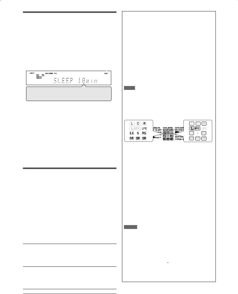
Turning off the power with the Sleep Timer
You can fall asleep while listening to music—Sleep Timer.
From the remote control ONLY:
Press SLEEP repeatedly.
•Each time you press the button, the shut-off time changes in 10-minute intervals. The SLEEP indicator lights up on the display.
SLEEP indicator 
10min = 20min = 30min = 40min =50min = 60min = 70min = 80min =90min = OFF (Canceled) = (Back to the beginning)
When the shut-off time comes:
The receiver turns off automatically.
To check the remaining time until the shut-off time:
Press SLEEP once.
The remaining time (in minutes) until the shut-off time appears.
• To change the shut-off time, press SLEEP repeatedly.
To cancel the Sleep Timer:
Press SLEEP repeatedly so that “SLEEP OFF” appears on the display. (The SLEEP indicator goes off.)
•The Sleep Timer is also canceled when you turn off the receiver.
Making sounds natural
JVC’s CC (Compression Compensative) Converter eliminates jitter and ripples, achieving a drastic reduction in digital distortion by processing the digital music data in 24 bitquantization and by expanding the sampling frequency
to 176.4 kHz (for fs 44.1 kHz signals)/192 kHz (for fs 48 kHz signals) on the front speakers.
By using the CC Converter, you can obtain a natural sound field from both digital and analog sources.
•Once you have made an adjustment, it is memorized for each source.
Press CC CONVERTER repeatedly.
•Each time you press the button, the mode changes as follows:
CC CNVRTR 1 Select when playing back an analog source or a digital source with non compressed digital sound signal (Linear PCM).
The CC CONVERTER 1 indicator lights up on the display.
CC CNVRTR 2 Select when playing back a source with compressed digital sound signal (Dolby Digital or DTS).
The CC CONVERTER 2 indicator lights up on the display.
CC CNVRTR OFF Select when not using the CC Converter.
Basic adjustment of auto memory
This receiver memorizes sound settings for each source:
•When you turn off the power
•When you change the source
When you change the source, the memorized settings for the newly selected source are automatically recalled. The following can be stored for each source:
•Video input setting (see page 21)
•Audio input setting (see page 21)
•CC Converter (see the left column)
•Midnight mode (see page 33)
•Digital equalization patterns (see page 36)
•Bass Boost (see page 37)
•Input attenuator mode (see page 37)
•Surround/DSP mode selection (see page 44)
NOTE
If the source is “FM” or “AM,” you can assign a different setting for each band.
Signal and speaker indicators on the display
Signal indicators |
|
|
|
|
Speaker indicators |
|||||||
|
|
|
|
|
|
|
|
|
|
|
|
|
|
|
|
|
|
|
|
|
|
|
|
|
|
|
|
|
|
|
|
|
|
|
|
|
|
|
|
|
|
|
|
|
|
|
|
|
|
|
|
|
|
|
|
|
|
|
|
|
|
|
|
|
|
|
|
|
|
|
|
|
|
|
|
|
|
|
|
|
|
|
|
|
|
|
|
|
|
|
|
|
|
|
|
|
|
|
|
|
|
|
|
|
|
|
|
|
|
|
|
|
|
|
|
|
|
|
|
|
|
|
|
|
|
|
|
|
|
The signal indicators light up as follows:
L:• When digital input is selected: Lights up when the left channel signal comes in.
•When analog input is selected: Always lights up.
R:• When digital input is selected: Lights up when the right channel signal comes in.
•When analog input is selected: Always lights up.
C:Lights up when the center channel signal comes in.
LS: |
Lights up when the left surround channel signal |
|
comes in. |
RS: |
Lights up when the right surround channel signal |
|
comes in. |
S:Lights up when monaural surround signal comes in.
SB: |
Lights up when the surround back channel signal |
|
comes in. |
LFE: |
Lights up when the LFE channel signal comes in. |
NOTES
•When “A MULTI” is selected for the audio input setting (see page 21), all the signal indicators except “SB” and “S” light up.
•When playing back multi-channel digital sound recorded in DVDAudio with HDMI connection (see pages 9 and 21), the signal indicators may not light up correctly.
The speaker indicators light up as follows:
•The subwoofer indicator ( ) lights up when “SUBWOOFER” is set to “YES.” For details, see page 30.
•The other speaker indicators light up only when the corresponding speaker is set to “SML (small)” or “LRG (large),” and also required for the current playback.
23
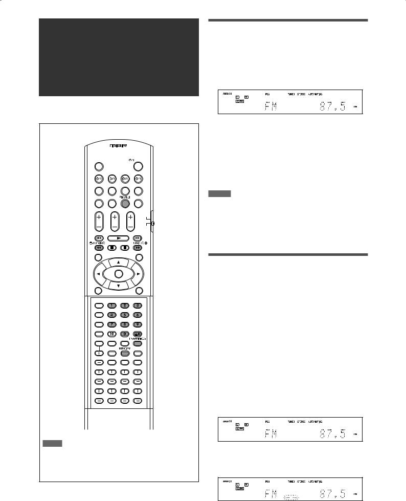
FM/AM tuner operations
FM/AM tuner operations are mainly done from the remote control.
NOTE
When you have selected “FM” or “AM” by using SOURCE SELECTOR on the front panel, the remote control may not work for tuner operations. To use the remote control for tuner operations, select “FM” or “AM” by using the FM/AM button on the remote control.
Tuning in to stations manually
From the remote control ONLY:
1 Press FM/AM to select the band.
The last received station of the selected band is tuned in.
•Each time you press the button, the band alternates between “FM” and “AM.”
2Press repeatedly or hold TUNING 9 or ( TUNING until the station you want is tuned in.
•Pressing (or holding) TUNING 9 increases the frequency.
•Pressing (or holding) ( TUNING decreases the frequency.
NOTES
•When you hold and release TUNING 9 or ( TUNING, the frequency keeps changing until a station is tuned in.
•When a station of sufficient signal strength is tuned in, the TUNED indicator lights up on the display.
•When an FM stereo program is received, the STEREO indicator also lights up.
Using preset tuning
Once a channel number is assigned to a station, the station can be quickly tuned in by selecting the number. You can preset up to 30 FM and 15 AM stations.
7 To store the preset stations
Before you start, remember...
There is a time limit in doing the following steps. If the setting is canceled before you finish, start from step 2 again.
From the remote control ONLY:
1Tune in to the station you want to preset (see “Tuning in to stations manually” above).
•If you want to store the FM reception mode for this station, select the FM reception mode you want. See “Selecting the FM reception mode” on page 25.
2Press MEMORY.
The channel number position starts flashing on the display for about 5 seconds.
24
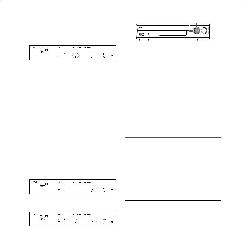
3Press the numeric buttons (0 – 9, h10) to select a channel number while the channel number position is flashing.
•For channel number 5, press 5.
•For channel number 10, press h10, 1, then 0.
•For channel number 25, press h10, 2, then 5.
4Press MEMORY again while the selected channel number is flashing on the
display.
The selected channel number stops flashing. The channel number is assigned to the station.
5Repeat steps 1 to 4 until you store all the stations you want.
To erase a stored preset station:
Storing a new station on a used channel number erases the previously stored one.
On the front panel:
2 1, 3
Before you start, remember...
There is a time limit in doing the following steps. If the setting is canceled before you finish, start from step 2 again.
1 Turn SOURCE SELECTOR to select “FM” or “AM.”
The last received station of the selected band is tuned in.
2 Press TUNER PRESET.
“P” appears on the display, and MULTI JOG now works for selecting preset channels.
3Turn MULTI JOG to select a preset channel number.
•To increase the preset channel numbers, turn MULTI JOG clockwise.
•To decrease the preset channel numbers, turn MULTI JOG counterclockwise.
7 To tune in a preset station
From the remote control:
1 Press FM/AM to select the band.
The last received station of the selected band is tuned in and the numeric buttons now work for selecting preset channels.
•Each time you press FM/AM, the band alternate between “FM” and “AM.”
2Press the numeric buttons (0 – 9, h10) to select a preset channel number.
•For channel number 5, press 5.
•For channel number 10, press h10, 1, then 0.
•For channel number 25, press h10, 2, then 5.
Selecting the FM reception mode
When an FM stereo broadcast is hard to receive or noisy, you can change the FM reception mode.
•You can store the FM reception mode for each preset station (see page 24).
From the remote control ONLY:
While listening to an FM station, press FM MODE.
•Each time you press the button, the FM reception mode alternates between “AUTO MUTING” and “MONO.”
AUTO MUTING |
Normally select this. |
|
When a program is broadcast in stereo, you |
|
will hear stereo sound; when in monaural, |
|
you will hear monaural sound. This mode is |
|
also useful to suppress static noise between |
|
stations. The AUTO MUTING indicator lights |
|
up on the display. |
|
|
MONO |
Select this to improve the reception (but |
|
stereo effect will be lost). |
|
In this mode, you will hear noise while |
|
tuning in to the stations. The AUTO MUTING |
|
indicator goes off from the display. (The |
|
STEREO indicator also goes off.) |
|
|
Initial setting: |
AUTO MUTING |
25
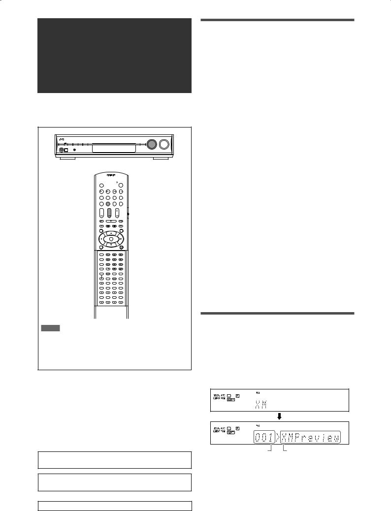
XM Satellite Radio operations
This is an XM Ready® receiver.
•Before operating, refer also to the manual of your XM Passport System (not supplied).
NOTE
When you have selected “XM” by using SOURCE SELECTOR on the front panel, the remote control may not work for XM Satellite Radio operations. To use the remote control for the XM Satellite Radio operations, select “XM” by using the XM button on the remote control.
7 About XM Satellite Radio
XM Satellite Radio is a satellite radio service with digitalquality sound and over 170 digital channels, the most commercial-free music in satellite radio services, live concerts plus exclusive original programming, the biggest names in news, talk, and entertainment, the most sports play-by-play including Major League Baseball®. For the latest channel listings and programming information, or to sign up, visit <http://www.xmradio.com>.
XM Ready® is a registered trademark of XM Satellite Radio Inc. All rights reserved.
Major League Baseball® is a registered trademark of Major League Baseball Properties, Inc.
For SIRIUS Satellite Radio operations, see page 47.
Preparation
To listening to XM Satellite Radio, you need the following:
–The XM Passport System*1 (not supplied)—XM Passport and XM Passport Home Dock
–Subscription to XM Satellite Radio*2
*1 To connect the XM Passport System with this receiver, see page 7.
*2 The following channels are available without subscription:
– Channel 0: This channel is for checking the XM Satellite Radio ID code.
– Channel 1: This is “XM Preview” channel.
How to subscribe
XM Satellite radio is a subscription service.
To subscribe to the XM Satellite Radio, visit the XM Satellite Radio’s web site at <http://xmradio.com/activation/>, or you can call 1-800-XM-RADIO (1-800-967-2346).
For subscription, you need to have the XM Satellite radio ID code. To check the ID code, follow the procedure below:
How to check the XM Satellite Radio ID code
After connection:
1Press XM on the remote control or turn SOURCE SELECTOR on the front panel to select “XM” as the source.
2Tune in to “Channel 0” (see “To tune in to channels” on page 27) to check your XM
Satellite Radio ID code.
The display alternately shows “RADIO ID” and the 8-digit (alphanumeric) ID code.
To cancel the ID code display
Select any channel other than “Channel 0.”
Listening to the XM Satellite Radio
1Press XM on the remote control or turn SOURCE SELECTOR on the front panel to
select “XM” as the source.
The last received channel is tuned in.
“XM” appears and then the channel name appears on the display.
Channel number |
Channel name |
2 Tune in to the desired channel.
You can tune in to channels with one of the following methods:
–Channel Search
–Category Search
–Direct Channel Access
For details, see “To tune in to channels” on page 27.
26
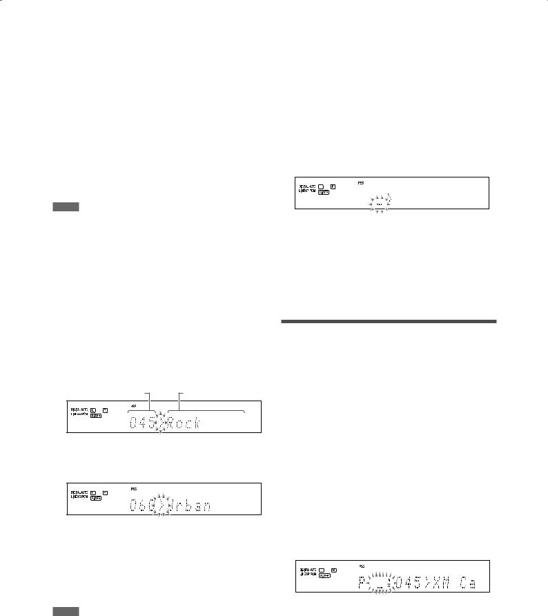
7 To tune in to channels
From the remote control ONLY:
Channel Search
You can search and tune in to all channels.
1Press XM to select “XM” as the source.
2Press repeatedly or hold CHANNEL +/– until the desired channel number appears on the display.
•Pressing (or holding) CHANNEL + increases the channel number.
•Pressing (or holding) CHANNEL – decreases the channel number.
NOTE
While searching, the invalid and unsubscribed channels are skipped.
Category Search
You can select the channel category and tune in to only the channels included in the selected category.
Before you start, remember...
There is a time limit in doing the following steps. If the setting is canceled before you finish, start from step 2 again.
1Press XM to select “XM” as the source.
2Press CAT 9 or ( CAT.
The receiver enters the Category Search mode.
The category name of the currently selected channel appears and “>” starts flashing on the display for about 15 seconds.
Channel number |
Category name |
3Press CAT 9 or ( CAT repeatedly to display the desired category name on the display while “>” is flashing.
4Press repeatedly or hold CHANNEL
+/– until the desired channel is tuned in.
•Pressing (or holding) CHANNEL + increases the channel number included in the selected category.
•Pressing (or holding) CHANNEL – decreases the channel number included in the selected category.
NOTE
While searching, the invalid and unsubscribed channels are skipped.
Direct Channel Access
You can tune in to the desired channel directly by entering the channel number.
Before you start, remember...
There is a time limit in doing the following steps. If the setting is canceled before you finish, start from step 2 again.
1Press XM to select “XM” as the source.
2Press the DIRECT button.
The receiver enters the Direct Access mode and the numeric buttons now work for entering channel numbers. The channel number position starts flashing on the display for about 5 seconds.
3Press the numeric buttons (0 – 9, h10) to enter the desired channel number while the channel number position is flashing.
•For channel number 005, press 5.
•For channel number 010, press h10, 1, then 0.
•For channel number 025, press h10, 2, then 5.
•For channel number 115, press h10, h10, 1, 1, then 5.
Using preset tuning
Once a preset number is assigned to a channel, the channel can be quickly tuned in by selecting the number. You can preset up to 30 channels.
7 To store the preset channels
Before you start, remember...
There is a time limit in doing the following steps. If the setting is canceled before you finish, start from step 2 again.
From the remote control ONLY:
1Tune in to the channel you want to preset (see “To tune in to channels” on the left column).
2Press MEMORY.
The preset number position starts flashing on the display for about 5 seconds.
3Press the numeric buttons (0 – 9, h10) to select a preset number while the preset number position is flashing.
•For preset number 5, press 5.
•For preset number 10, press h10, 1, then 0.
•For preset number 25, press h10, 2, then 5.
Continued on the next page
27
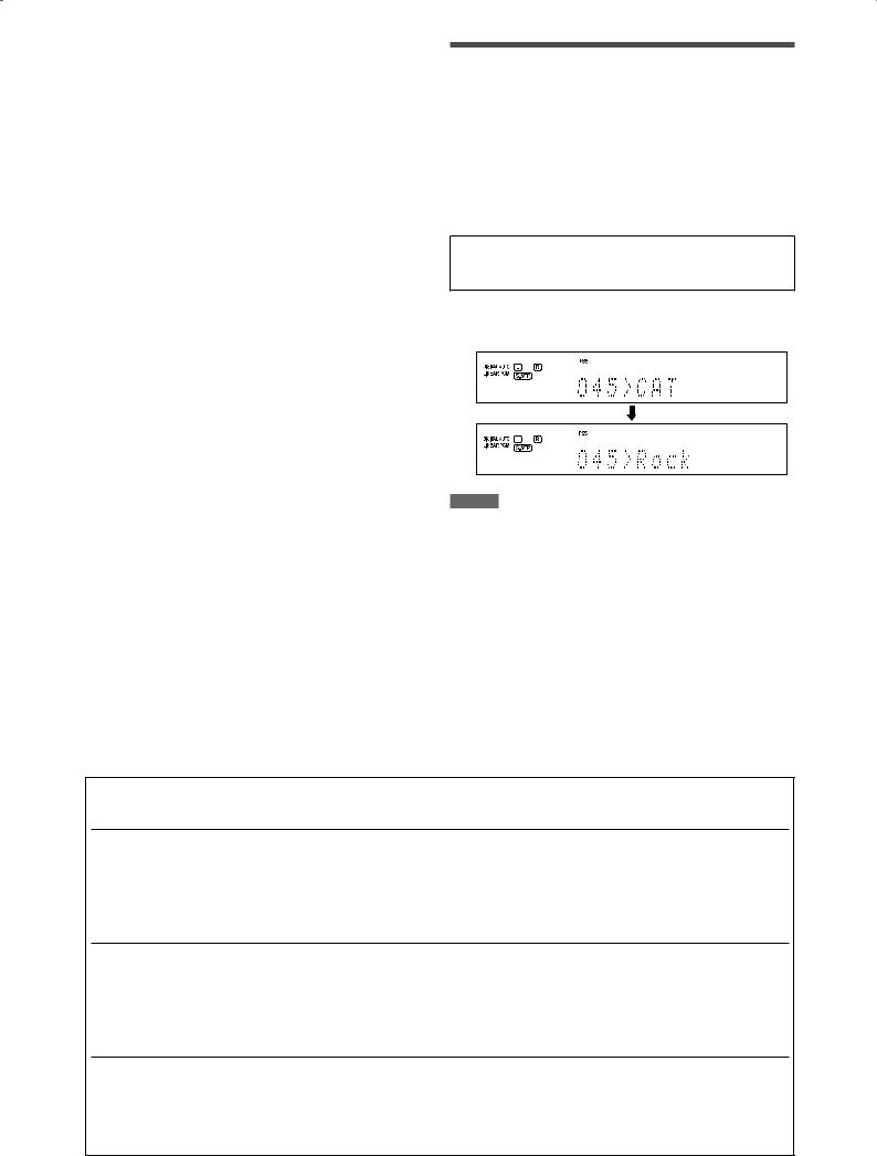
4Press MEMORY again while the selected preset number is flashing on the display.
5Repeat steps 1 to 4 until you store all the desired channels.
To erase a stored preset channel
Storing a new channel on a used preset number erases the previously stored one.
7 To tune in a preset channel
From the remote control:
1 Press XM.
The last received channel is tuned in.
2Press the numeric buttons (0 – 9, h10) to select a preset channel number.
•For preset number 5, press 5.
•For preset number 10, press h10, 1, then 0.
•For preset number 25, press h10, 2, then 5.
Changing the channel information
While listening to the XM Satellite Radio, the currently selected channel information appears on the display. You can change the type of channel information.
From the remote control ONLY:
Press DISPLAY.
Each time you press the button, the channel information changes as follows:
CHAN (channel name)* = NAME (artist name/feature) = TITLE (song/program title) = CAT (category name) = (Back to the beginning)
* CHAN (channel name) is the initial setting.
EX.: When the category name is selected:
After 1 second
On the front panel:
Before you start, remember...
There is a time limit in doing the following steps. If the setting is canceled before you finish, start from step 2 again.
1 Turn SOURCE SELECTOR to select “XM.”
The last received channel is tuned in.
2 Press TUNER PRESET.
“P” flashes on the display, and MULTI JOG now works for selecting preset channels.
3Turn MULTI JOG to select a preset number.
•To increase the preset numbers, turn MULTI JOG clockwise.
•To decrease the preset numbers, turn MULTI JOG counterclockwise.
NOTES
•If you turn off the power or select another source, the display is changed back to the initial setting.
•When you tune in to another channel, the channel name appears on the display and then the channel information you have selected appears.
•When all the text information cannot be shown on the display at a time, the text scrolls.
•Some characters cannot be displayed correctly.
7 Messages on the display
When problems occur, a message appears on the display. In this case, refer to the following solution.
Message |
Possible cause |
Solution |
NO SIGNAL |
Signals are too weak. |
Move the XM Passport Home Dock antenna |
|
|
near a south-facing window or where |
|
|
“Channel 1” can be heard clearly. |
|
|
|
CHECK ANTENNA |
The XM Passport Home Dock antenna is |
|
not connected properly. |
Check the connection (see page 7).
LOADING |
This receiver is loading the channel |
It takes a few minutes to complete. Wait until |
|
information and audio data. |
loading is finished. |
|
|
|
OFF AIR |
Selected channel is not currently |
Select another channel. |
|
broadcasting any signal. |
|
|
|
|
UPDATING |
The latest encryption code is being |
|
updated. |
Wait until updating is finished.
• |
Channel number and “ |
----- ” |
|
No text information for the selected |
|
|
• |
Preset number, channel |
|
channel is available. |
— |
||
|
number, and “-----” |
|
|
|
|
|
|
|
|
|
|
||
• |
Channel number and “CH--- |
” |
Selected channel does not exist or is not |
— |
||
• |
Preset number and “ |
<CH |
” |
subscribed yet. |
||
|
||||||
|
|
|
|
|
|
|
28
 Loading...