


SERVICE MANUAL
STANDBY/ON |
CD/ |
TUNER/ |
|
|
RANDOM |
BAND |
TAPE |
|
1 |
2 |
3 |
DISPLAY |
|
|
|
|
4 |
5 |
6 |
HBS/ |
|
|
|
PRESET EQ |
|
|
|
|
7 |
8 |
9 |
FM MODE |
|
|
OVER |
/BEAT CUT |
|
|
|
|
0 |
|
|
UP |
PROGRAM/ |
INTRO |
+ |
CLOCK SET |
|||
PRESET |
REPEAT |
MUTING |
GROUP |
DOWN |
|
|
– |
VOLUME
RM-SRCEX30J REMOTE CONTROL
CD PORTABLE SYSTEM
RC-EX30B
SERVICE POLICY
No service part is available for this model. Exchange only.
TAPE
RANDOM CD
GROUP
TUNER
BAND
REMOTE SENSOR
|
PROGRAM/ |
|
CLOCK SET |
PRESET |
|
DOWN |
UP |
|
PRESET |
|
HBS/ |
|
PRESET EQ |
PUSH
OP
ST
SE
AU
Y/P
PLA
DISPLAY
|
Area suffix |
A ------------------------ |
Australia |
B ------------------------------ |
U.K. |
E ---------- |
Continental Europe |
EN ----------- |
Northern Europe |
EV ------------- |
Eastern Europe |
TABLE OF CONTENTS
1 PRECAUTION. . . . . . . . . . . . . . . . . . . . . . . . . . . . . . . . . . . . . . . . . . . . . . . . . . . . . . . . . . . . . . . . . . . . . . . . . 1-3 2 SPECIFIC SERVICE INSTRUCTIONS . . . . . . . . . . . . . . . . . . . . . . . . . . . . . . . . . . . . . . . . . . . . . . . . . . . . . . 1-4 3 DISASSEMBLY . . . . . . . . . . . . . . . . . . . . . . . . . . . . . . . . . . . . . . . . . . . . . . . . . . . . . . . . . . . . . . . . . . . . . . . 1-5 4 ADJUSTMENT . . . . . . . . . . . . . . . . . . . . . . . . . . . . . . . . . . . . . . . . . . . . . . . . . . . . . . . . . . . . . . . . . . . . . . . 1-14 5 TROUBLESHOOTING . . . . . . . . . . . . . . . . . . . . . . . . . . . . . . . . . . . . . . . . . . . . . . . . . . . . . . . . . . . . . . . . . 1-15
COPYRIGHT © 2004 Victor Company of Japan, Limited
No.MB279
2004/6
|
|
SPECIFICATION |
|
|
|
CD player |
CD capacity |
1 CD |
|
|
|
|
Signal-to-noise ratio |
75 dB |
|
|
|
|
Dynamic range |
60 dB |
|
|
|
Tuner |
Frequency range |
FM 87.5 - 108.0 MHz |
|
|
AM 522 - 1 629 kHz |
|
Antennas |
Telescopic antenna for FM |
|
|
Ferrite core antenna for AM |
|
|
|
Cassette deck |
Frequency response |
60 Hz - 10 000 Hz |
|
|
|
|
Wow & flutter |
0.15% (WRMS) |
|
|
|
|
Fast wind time |
Approx. 150 sec. (C-60 cassette) |
|
|
|
General |
Speakers |
9 cm cone × 2 |
|
|
|
|
Speaker impedance |
4 Ω |
|
|
|
|
Output power |
4 W (2 W + 2 W) at 4 Ω (10% THD) |
|
|
|
|
Output terminals |
PHONES × 1 |
|
|
|
|
Power supply |
AC 230 V , 50 Hz DC 9 V (R20 (SUM-1)/D (13D)-size batteries × 6) |
|
|
|
|
Power consumption |
18 W (at operation) 3 W (on standby) |
|
|
|
|
Dimensions |
420 mm × 178 mm × 250 mm (W/H/D) |
|
|
|
|
Mass |
Approx. 3.2 kg (without batteries) |
|
|
|
Design and specifications are subject to change without notice.
1-2 (No.MB279)
SECTION 1
PRECAUTION
This service manual does not describe PRECAUTION.
(No.MB279)1-3
SECTION 2
SPECIFIC SERVICE INSTRUCTIONS
This service manual does not describe SPECIFIC SERVICE INSTRUCTIONS.
1-4 (No.MB279)
SECTION 3
DISASSEMBLY
3.1Main body
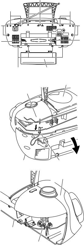
3.1.1Removing the rear cover assembly section (See Fig.1 to 3)
(1)Remove the eight screws A, the three screws B and the four screws C attaching the rear cover assembly on the back of the body.
(2)Remove the battery cover on the back of the body and remove the two screws D attaching the rear cover assembly.
(3)Move the rear cover assembly in the direction of the arrow and remove. At this time, disconnect the wire from connector CN406 and FM-ANT on the main board.
|
B |
C |
C |
A |
A |
D |
D |
A |
Battery cover |
|
|
|
Fig.1 |
Top cover assembly
Tuner board
Rear cover assembly |
FM-ANT |
|
Fig.2
Front panel assembly
Main board
CN406
Fig.3
(No.MB279)1-5

3.1.2 Removing the top cover assembly section and the front panel assembly section (See Fig.4 to 8)
• Prior to performing the following procedure, remove the rear cover assembly.
(1) Release the tab a of the handle using a screwdriver. Return E E the handle below and pull out in the direction of the arrow.
(2)Disconnect the wire from connector CN404 and 4pin connector on the main board.
(3) Remove the six screws E and the two screws F attaching the top cover.
(4)Draw out the top cover assembly from the front panel assembly section backward.
(5)Disconnect the wire from connector CN501 and CN506 on the main board, and disconnect the card wire from connector CN507 and CN508.
(6)Disconnect the wire from board connector CON301 of the cassette mechanism assembly.
tab a |
tab a |
|
Handle
Fig.4
Top cover assembly |
Front panel assembly |
Main board
CN404
4pin connector
Fig.5
E E
Fig.6
CD door
F
Fig.7
Main board CN508,CN507 Main board
Cassette mechanism board CN501,CN506 CON301
Fig.8
1-6 (No.MB279)

3.1.3Removing the main body (See Fig.9, 10)
Caution:
Make sure to solder the short-circuit point on the CD servo board before disconnecting the card wire from connector CN201 on the main board and from the CD servo board. If you don't observe this instruction, the pickup may be damaged.
(1)Remove the eight screws G attaching the main board on the top cover assembly.
(2)Disconnect the wire from connector CN501, CN502, CN511, CN202, CN401 and CN504 on the main board.
(3)Disconnect the card wire from connector CN201 on the main board.
Caution:
If necessary, cut the band.
G |
|
G |
Band |
|
CN502 |
|
|
|
|
|
|
|
|
|
CN511 |
CN501
CN504 |
CN202 CN401 |
CN201
G G G
Fig.9
CD servo board
Short-circuit point
Unsolder
Fig.10
(No.MB279)1-7

3.1.4 Tuner board (See Fig.11)
•Prior to performing the following procedure, remove the main board.
(1) Remove the three screws H attaching the tuner board.
H |
3.1.5 Removing the top switch board (See Fig.12)
•Prior to performing the following procedure, remove the main board and the tuner board.
(1) Remove the four screws J attaching the top switch board.
Tuner board
H
Fig.11
Top switch board
J
J |
Fig.12
1-8 (No.MB279)

3.1.6Removing the volume board and the power switch board (See Fig.13 to 16)
• Prior to performing the following procedure, remove the main |
Tab b |
|
board. |
||
|
||
(1) Remove the three screws K attaching the volume board. |
|
(2)Pull out the volume board from the volume knob.
(3)Remove the four screws L attaching the cover on the side of the power switch.
(4)Release the three tabs b of the cover on the side of the
power switch. |
|
|
(5) Remove the three screws M attaching the power switch |
|
|
board to the cover. |
|
|
Caution: |
|
|
If necessary, unsolder the solder points. |
|
|
Volume board |
K |
Side top cover |
|
|
|
|
|
L |
|
|
Fig.15 |
|
|
M |
Switch board
Solder point
K |
M
Solder point
Fig.13
Volume knob |
Switch board |
Side top cover |
Power switch board |
|
|
Fig.16
Top cover assembly
Solder point

 K
K
Volume board
K
Fig.14
(No.MB279)1-9
 Loading...