


RC-BX33SL
SERVICE MANUAL
PORTABLE CD SYSTEM
RC-BX33SL
Area Suffix
UX---Saudi and relative
U---Except ux
IMPORTANT
PLEASE TAKE NOTE BEFORE ORDERING
1.Order all service parts through JVC Asia Pte Ltd.- Customer Satisfaction Dept.
2.Two orders are available: Initial order and last order (Before End Of Line)
3.Minimum order quantity: 100pcs
4.Delivery term: Minimum 2 months upon confirmation of order.
Contents
Safety precautions ............................................................ |
1-2 |
Preventing static electricity ............................................... |
1-3 |
Disassembly method ......................................................... |
1-4 |
Adjustment method............................................................ |
1-7 |
Description of major IC .................................................. |
1-13 |
COPYRIGHT 2001 JVC ASIA PTE LTD |
No: 28208 |
|
DEC. 2001 |
RC-BX33SL
Safety precautions
1.This design of this product contains special hardware and many circuits and components specially for safety purposes. For continued protection, no changes should be made to the original design unless authorised in writing by the manufacturer. Replacement parts must be identical to those used in the original circuits. Services should be performed by qualified personnel only.
2.Alterations of the design or circuitry of the product should not be made. Any design alterations of the product should not be made. Any design alterations or additions will void the manufacturer’s warranty and will further relieve the manufacture of responsibility for personal injury or property damage resulting therefrom.
3.Many electrical and mechanical parts in the products have special safety-related characteristics. These characteristics are often not evident from visual inspection nor can the protection afforded by them necessarily be obtained by using replacement components rated for higher voltage, the Parts List of Service Manual. Electrical components having such features are identified by shading on the
schematics and by ( ) on the Parts List in the Service Manual. The use of a substitute replacement which does not have the same safety characteristics as the recommended replacement parts shown in the Parts List of Service Manual may create shock, fire, or other hazards.
4.The leads in the products are routed and dressed with ties, clamps, tubing’s, barriers and the like to be separated from live parts, high temperature parts, moving parts and/or sharp edges for the prevention of electric shock and fire hazard. When service is required, the original lead routing and dress should be observed, and it should be confirmed that they have been returned to normal, after re-assembling.
5.Leakage current check (Electrical Shock hazard testing)
After re-assembling the product, always perform an isolation check on the exposed metal parts of the product (antenna terminals, knobs, metal cabinet, screw heads, headphone jack, control shafts, etc.) to be sure the product is safe to operate without danger of electrical shock.
Do not use a line isolation transformer during this check.
•Plug the AC line cord directly into the AC outlet. Using a “Leakage Current Tester”, measure the leakage current from each exposed metal parts of the cabinet, particularly and exposed metal part having a return path to the chassis, to a known good earth ground. Any leakage current must not exceed 0.5mA AC (r.m.s.)
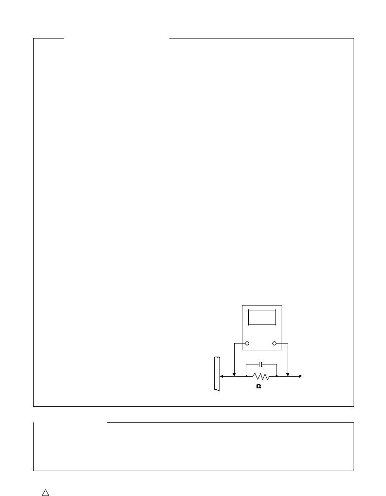
•Alternate check method
Plug the AC line cord directly into the AC outlet. Use an AC voltmeter having, 1,000 ohms per volt or more sensitivity in the following manner. Connect a 1,500 10W resistor paralleled by a
0.15µF AC-type capacitor between an exposed metal part and a known good earth ground. Measure the AC voltage across the resistor with the AC voltmeter.
Move the resistor connection to each exposed metal part, particularly any exposed metal part having a return path to the chassis, and measure the AC voltage across the resistor. Now, reverse the plug in the AC outlet and repeat each measurement. voltage measured Any must not exceed 0.75 V AC (r.m.s.). This corresponds to 0.5 mA AC (r.m.s.).
AC Voltmeter (Having 1000 ohms/volts,
or more sensitivity
0.15µF AC TYPE |
Place this |
|
|
|
probe on |
1500 10W |
each exposed |
metal part. |
Good earth ground
 Warning
1.This equipment has been designed and manufactured to meet international safety standards.
2.It is the legal responsibility of the repairer to ensure that these safety standards are maintained.
3.Repairs must be made in accordance with the relevant safety standards.
4.It is essential that safety critical components are replaced by approved parts.
5.If mains voltage selector is provided, check setting for local voltage.
! CAUTION Burrs formed during moulding may be left over on some parts of the chassis. Therefore, pay attention to such burrs in the case of performing repair of this system.
1-2
RC-BX33SL
Preventing static electricity
Electrostatic discharge (ESD), which occurs when static electricity stored in the body, fabric, etc. is discharged, can destroy the laser diode in the traverse unit (optical pickup). Take care to prevent this when performing repairs.
1.1. Grounding to prevent damage by static electricity
Static electricity in the work area can destroy the optical pickup (laser diode) in devices such as DVD players. Be careful to use proper grounding in the area where repairs are being performed.
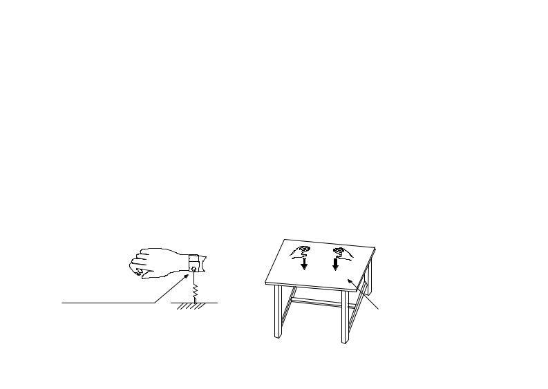
1.1.1. Ground the workbench
1. Ground the workbench by laying conductive material (such as a conductive sheet) or an iron plate over it before placing the traverse unit (optical pickup) on it.
1.1.2. Ground yourself
1. Use an anti-static wrist strap to release any static electricity built up in your body.
(caption)
Anti-static wrist strap
Conductive material (conductive sheet) or iron plate
1.1.3. Handling the optical pickup
1.In order to maintain quality during transport and before installation, both sides of the laser diode on the replacement optical pickup are shorted. After replacement, return the shorted parts to their original condition. (Refer to the text.)
2.Do not use a tester to check the condition of the laser diode in the optical pickup. The tester’s internal power source can easily destroy the laser diode.
1.2. Handling the traverse unit (optical pickup)
1.Do not subject the traverse unit (optical pickup) to strong shocks, as it is a sensitive, complex unit.
2.Cut off the shorted part of the flexible cable using nippers, etc. after replacing the optical pickup. For specific details, refer to the replacement procedure in the text. Remove the anti-static pin when replacing the traverse unit. Be careful not to take too long a time when attaching it to the connector.
3.Handle the flexible cable carefully as it may break when subjected to strong force.
4.It is not possible to adjust the semi-fixed resistor that adjusts the laser power. Do not turn it.
1-3
RC-BX33SL
Disassembly method
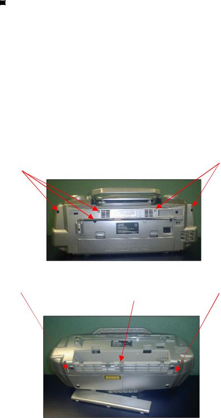
Removing the rear panel
1.From behind the body, remove the Five screws A retaining the rear panel.
2.Open the Battery door, then remove One Screw B retaining in the battery compartment bottom side.
3Then remove the Two screws C retaining the bottom of rear panel.
4Take out the rear panel from the body. And disconnect the CN302 on the main board right side.
Note:
Be careful of the FM antenna white wire, it is connection with the tuner PCB up side. You can directly take out from the tuner PCB.
When you re-assembly the product, plug the FM antenna white wire into the Tuner
PCB'S "FM ANT" position.
Screw A.
Screw A.
Screw C. |
Screw C. |
|
Screw B. |
1-4
RC-BX33SL
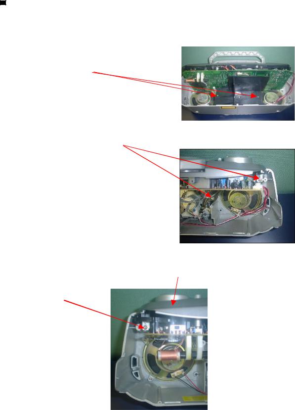
Removing the Main Board PCB (1)
1.Open & remove the rear panel
2.Remove the Two Screws D on the Black Backet, then take out the black backet on the
front panel.
Screws D.
3Remove the Two Screws E retaining on the left of front panel.
Screws E.
4Remove the One Screw F retaining on the right of front panel.
Top panel
Screw F.
1-5

RC-BX33SL
Removing the Main Board PCB (2)
5Disconnect the CN201, CN202 & C301 on the top of the
Main Board PCB.
Front Panel |
CN 201 |
Main PCB |
CN 202 |
CN 301 |
Top Panel
6Then, take out the top panel from the front panel.
7Remove the nine screws G from the Main Board PCB.
Screw G. |
Screw G. |
Screw G.
8Take out the Main Board PCB from the front panel, & disconnect the CN901 & CN903 on the Main Board PCB.
1-6
Adjustment method
Measurement instruments required for adjustment
1Low frequency oscillator
This oscillator should have a capacity to output 0dB to 600 at an oscillation frequency of 50Hz-20KHz
2Electronic voltmeter
3Distortion meter
4Frequency counter
5Wow & flutter meter
6Test tape
TCC-112: Tape speed and running unevenness (3KHz) TCC-140: Reference level (1KHz)
TCC-182A: Head angle (8KHz), playback frequency characteristics (1KHz) and dubbing frequency
characteristics (125Hz and 8KHz)
7Blank tape
TYPE I : TDK-D60
8Torque gauge : For play and back tension FWD(CT-120m), and FF/REW(CT-F)
Measurement conditions
|
Power supply voltage |
-------------- |
AC120V (60Hz) |
|||
|
Reference output -------------- |
Speaker : 0.63V/8 |
||||
|
|
|
|
Headphone : 0.245V/32 |
||
|
Input for |
confirming |
recording |
and |
------- CD : -10dB |
|
|
playback |
characteristics |
|
|
||
|
Measurement output terminal ------- |
|
Speaker CN301 |
|||
|
* Load |
resistance -------------------------------------- |
|
|
8 |
|
|
Radio |
Input signal |
|
|
|
|
|
|
|
|
|||
|
|
|
|
|||
|
AM frequency -------------------------------- |
|
|
400Hz |
||
|
AM modulation ---------------------------------- |
|
|
30% |
||
|
FM frequency --------------------------------- |
|
|
1 KHz |
||
|
FM frequency deviation ------------------ |
|
22.5KHz |
|||
RC-BX33SL
Tuner section
Reference measurement ----- 26.1mV(0.63/8 ) output
Input positions ----- AM : Standard loop antenna FM : TP1 (hot) and TP2 (GND)
Precautions for measurement
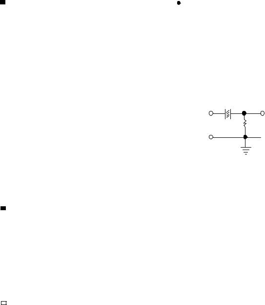
1Direct connect to the IF sweeper output side and 1UF and 22 Kohm connect to the sweeper input side. Same as FIG1.
1 U
IC101 |
TP16 |
PIN18 |
22 K |
 TP8
TP8
2The IF sweeper output level should be made as low as possible within the adjustable range.
3Since the IF sweeper is a fixed device, there is no to adjust this sweeper.
4Since a ceramic oscillator is used, there is no need to perform any MIX adjustment.
5Since a fixed coil is used, there is no need to adjustment the FM tracking.
6The input and output earth systems are separated.
In case of simultaneously measuring the voltage in both of the input and output systmes with and electronic voltmeter for two channels, therefore, the earth should be connected particularly carefully.
7For connecting a dummy resistor when measuring the output, use the wire with a greater code size.
8Whenever any mixed tape is used, use the band pass filter (DV-12V).
1-7
 Loading...