


HOME CINEMA CONTROL CENTER DVD VIDEO PLAYER
RX-ES1SL
XV-N55SL
INSTRUCTIONS
For Customer Use:
Enter below the Model No. and Serial No. which are located either on the rear, bottom or side of the cabinet. Retain this information for future reference.
Model No.
Serial No.
LVT1002-001E
[B]

Warnings, Cautions and Others
IMPORTANT for the U.K.
DO NOT cut off the mains plug from this equipment. If the plug fitted is not suitable for the power points in your home or the cable is too short to reach a power point, then obtain an appropriate safety approved extension lead or consult your dealer.
BE SURE to replace the fuse only with an identical approved type, as originally fitted.
If nonetheless the mains plug is cut off ensure to remove the fuse and dispose of the plug immediately, to avoid a possible shock hazard by inadvertent connection to the mains supply.
If this product is not supplied fitted with a mains plug then follow the instructions given below:
IMPORTANT
DO NOT make any connection to the terminal which is marked with the letter E or by the safety earth symbol or coloured green or green-and- yellow.
The wires in the mains lead on this product are coloured in accordance with the following code:
Blue : Neutral
Brown : Live
As these colours may not correspond with the coloured markings identifying the terminals in your plug proceed as follows:
The wire which is coloured blue must be connected to the terminal which is marked with the letter N or coloured black.
The wire which is coloured brown must be connected to the terminal which is marked with the letter L or coloured red.
IF IN DOUBT - CONSULT A COMPETENT ELECTRICIAN.
CAUTION
To reduce the risk of electrical shocks, fire, etc.:
1.Do not remove screws, covers or cabinet.
2.Do not expose this appliance to rain or moisture.
Caution––STANDBY/ON  switch!
Disconnect the mains plug to shut the power off completely. The STANDBY/ON  switch in any position does not disconnect the mains line. The power can be remote controlled.
G-1
IMPORTANT FOR LASER PRODUCTS
1.CLASS 1 LASER PRODUCT
2.CAUTION: Do not open the top cover. There are no user serviceable parts inside the Unit; leave all servicing to qualified service personnel.
3.CAUTION: Visible and invisible laser radiation when open and interlock failed or defeated. Avoid direct exposure to beam.
4.REPRODUCTION OF LABEL: CAUTION LABEL, PLACED INSIDE THE UNIT.
CAUTION
•Do not block the ventilation openings or holes.
(If the ventilation openings or holes are blocked by a newspaper or cloth, etc., the heat may not be able to get out.)
•Do not place any naked flame sources, such as lighted candles, on the apparatus.
•When discarding batteries, environmental problems must be considered and local rules or laws governing the disposal of these batteries must be followed strictly.
•Do not expose this apparatus to rain, moisture, dripping or splashing and that no objects filled with liquids such as vases, shall be placed on the apparatus.
G-2
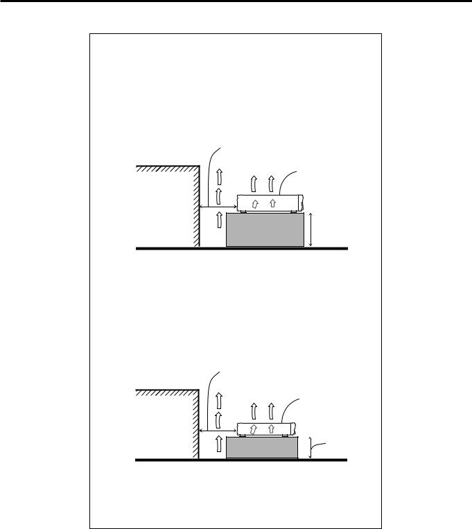
Caution: Proper Ventilation for RX-ES1SL
To avoid risk of electric shock and fire and to protect from damage.
Locate the apparatus as follows:
Front: |
No obstructions open spacing. |
Sides: |
No obstructions in 10 cm from the sides. |
Top: |
No obstructions in 10 cm from the top. |
Back: |
No obstructions in 15 cm from the back |
Bottom: |
No obstructions, place on the level surface. |
In addition, maintain the best possible air circulation as illustrated.
Spacing 15 cm or more
RX-ES1SL
Wall or obstructions
Stand height
 15 cm or more
Floor
Caution: Proper Ventilation for XV-N55SL
To avoid risk of electric shock and fire and to protect from damage. Locate the apparatus as follows:
Front: |
No obstructions open spacing. |
Sides: |
No obstructions in 3 cm from the sides. |
Top: |
No obstructions in 5 cm from the top. |
Back: |
No obstructions in 15 cm from the back |
Bottom: |
No obstructions, place on the level surface. |
In addition, maintain the best possible air circulation as illustrated.
Spacing 15 cm or more
XV-N55SL
Wall or obstructions
Stand height 5 cm or more
Floor
*Do not stack XV-N55SL and RX-ES1SL.
G-3

SAFETY INSTRUCTIONS
“SOME DOS AND DON’TS ON THE SAFE USE OF EQUIPMENT”
This equipment has been designed and manufactured to meet international safety standards but, like any electrical equipment, care must be taken if you are to obtain the best results and safety is to be assured.
Do read the operating instructions before you attempt to use the equipment.
Do ensure that all electrical connections (including the mains plug, extension leads and interconnections between pieces of equipment) are properly made and in accordance with the manufacturer’s instructions. Switch off and withdraw the mains plug when making or changing connections.
Do consult your dealer if you are ever in doubt about the installation, operation or safety of your equipment.
Do be careful with glass panels or doors on equipment.
DON’T continue to operate the equipment if you are in any doubt about it working normally, or if it is damaged in any way – switch off, withdraw the mains plug and consult your dealer.
DON’T remove any fixed cover as this may expose dangerous voltages.
DON’T leave equipment switched on when it is unattended unless it is specifically stated that it is designed for unattended operation or has a standby mode.
Switch off using the switch on the equipment and make sure that your family know how to do this.
Special arrangements may need to be made for infirm or handicapped people.
DON’T use equipment such as personal stereos or radios so that you are distracted from the requirements of traffic safety. It is illegal to watch television whilst driving.
DON’T listen to headphones at high volume as such use can permanently damage your hearing.
DON’T obstruct the ventilation of the equipment, for example with curtains or soft furnishings.
Overheating will cause damage and shorten the life of the equipment.
DON’T use makeshift stands and NEVER fix legs with wood screws — to ensure complete safety always fit the manufacturer’s approved stand or legs with the fixings provided according to the instructions.
DON’T allow electrical equipment to be exposed to rain or moisture.
ABOVE ALL
—NEVER let anyone, especially children, push anything into holes, slots or any other opening in the case -this could result in a fatal electrical shock.;
—NEVER guess or take chances with electrical equipment of any kind — it is better to be safe than sorry!
G-4

Table of Contents
Parts identification ................................................ |
2 |
Getting started ...................................................... |
5 |
Precautions ................................................................................. |
5 |
Checking the supplied accessories ............................................ |
5 |
Putting batteries in the remote control ........................................ |
5 |
Connecting the FM and AM (MW) antennas .............................. |
6 |
Connecting the speakers and DVD player ................................. |
7 |
Connecting other video components .......................................... |
8 |
Connecting the power cord ....................................................... |
10 |
RX-ES1SL |
|
Basic operations ................................................ |
11 |
1 Turn on the power .................................................................. |
11 |
2 Select the source to play ....................................................... |
11 |
3 Adjust the volume ................................................................. |
12 |
Selecting the digital decode mode ............................................ |
12 |
Activating TV Direct .................................................................. |
13 |
Turning off the sounds temporarily—Muting ............................. |
13 |
Turning off the power with the Sleep Timer .............................. |
14 |
Changing the display brightness .............................................. |
14 |
Speaker settings ................................................. |
15 |
Setting the speakers information automatically |
|
—Smart Surround Setup .................................................... |
15 |
Setting the speakers and subwoofer information quickly |
|
—Quick Setup .................................................................... |
16 |
Setting the speakers and subwoofer information manually |
|
—Manual Setup .................................................................. |
17 |
Basic settings ..................................................... |
19 |
Operating procedure ................................................................. |
19 |
Setting the digital Input (DIGITAL IN) terminals |
|
—DIGITAL IN ...................................................................... |
19 |
Setting Auto Surround—AUTO SR ........................................... |
20 |
Setting the Auto Function Mode—MODE ................................. |
20 |
Sound adjustments ............................................ |
21 |
Operating procedure ................................................................. |
21 |
Adjusting the tone—BASS, TREBLE ........................................ |
21 |
Adjusting the subwoofer output level—SUBWFR ..................... |
21 |
Adjusting the front speakers output balance—BAL .................. |
22 |
Reinforcing the bass—B.BOOST ............................................. |
22 |
Attenuating the input signal—ATT ............................................ |
22 |
Tuner operations ................................................ |
23 |
Tuning in to stations manually .................................................. |
23 |
Using preset tuning ................................................................... |
23 |
Selecting the FM reception mode ............................................. |
24 |
Using the RDS (Radio Data System) to |
|
receive FM stations ............................................................ |
25 |
Searching for a program by PTY codes .................................... |
26 |
Switching to broadcast program of your choice temporarily ..... |
27 |
Creating realistic sound fields ............................ |
28 |
Reproducing theater ambience ................................................. |
28 |
Introducing the Surround/DSP modes ....................................... |
28 |
About relations between speaker layout |
|
and Surround/DSP modes .................................................. |
30 |
Using Surround modes ............................................................. |
30 |
Using DSP modes .................................................................... |
32 |
Using the DVD MULTI playback mode ................. |
34 |
Activating the DVD MULTI playback mode ................................ |
34 |
Adjusting the speaker output level ............................................. |
34 |
XV-N55SL |
|
Before operation ................................................. |
35 |
About this manual ..................................................................... |
35 |
About discs ............................................................................... |
35 |
Basic operations ................................................ |
36 |
Turning on/off the player ........................................................... |
36 |
Initial setup ............................................................................... |
36 |
Basic playback .......................................................................... |
37 |
Resuming playback .................................................................. |
38 |
Various speed playback ............................................................ |
39 |
Locating the beginning of a scene or song ............................... |
40 |
Advanced operations ......................................... |
41 |
Playing from a specific position ................................................ |
41 |
Changing the playback order .................................................... |
42 |
Repeat playback ....................................................................... |
44 |
Changing the language, sound and scene angle ..................... |
45 |
Special picture/sound effect ...................................................... |
46 |
Menu bar functions ................................................................... |
47 |
MP3/WMA disc pla yback .................................... |
49 |
Operations ................................................................................ |
49 |
JPEG disc pla yback ............................................ |
51 |
About JPEG discs ..................................................................... |
51 |
Basic operations ....................................................................... |
51 |
Viewing pictures continuously (slide show mode) .................... |
52 |
Changing the initial settings ............................... |
54 |
Selecting preferences ............................................................... |
54 |
Limiting playback by children .................................................... |
57 |
Additional information ........................................ |
59 |
Appendix A: Country/Area code list for Parental Lock ............ |
59 |
Appendix B: Table of languages and their abbreviations ........ |
60 |
Appendix C: Digital output signal chart .................................... |
60 |
Appendix D: Glossary .............................................................. |
61 |
Operating other JVC pr oducts ............................. |
62 |
Operating other manufacturers’ equipment ............ |
63 |
Troubleshooting .................................................. |
65 |
Specifications ...................................................... |
68 |
1

Parts identification |
|
|
|
|
|
|
|
|
Remote control |
|
See pages in parentheses for details. |
|
|||||
|
1 |
TV DIRECT button (13) |
|
|
||||
When operating the receiver (RX-ES1SL), set the mode |
2 |
Standby/on buttons (11, 36, 62 – 64) |
|
|||||
|
|
AUDIO, DVD |
, VCR |
, STB |
, TV |
|||
selector (h) to “AUDIO/TV/VCR/STB.” |
|
|
|
|||||
|
3 |
Source selecting buttons (11) |
|
|
||||
When operating the player (XV-N55SL), set the mode |
|
|
||||||
|
DVD, VCR, STB, TV, DVD MULTI, FM/AM |
|||||||
selector (h) to “DVD.” |
|
|
||||||
|
4 |
CHANNEL +/– buttons (62 – 64) |
|
|||||
|
|
|
||||||
|
|
5 |
TV VOL (volume) +/– buttons (62, 64) |
|
||||
|
|
6 |
• |
Operating buttons for video components (62, 64) |
||||
|
|
|
|
4, 3, ¢, 1, 7, 8, ¡ |
|
|
||
|
|
|
• |
Operating buttons for tuner (23, 24) |
|
|||
|
|
|
|
TUNING 9, TUNING (, FM MODE, MEMORY |
||||
|
|
7 |
• |
Operating buttons for DVD |
|
|
||
1 |
|
|
|
TOP MENU, MENU, CHOICE, ON SCREEN, ENTER, |
||||
|
|
|
|
3, 2, 5, ∞ |
|
|
|
|
2 |
|
|
• |
Operating buttons for RDS (25 – 27) |
|
|||
|
|
|
|
PTY 9, PTY (, PTY SEARCH, TA/NEWS/INFO, DISPLAY |
||||
3 |
|
8 |
SUBTITLE button (45) |
|
|
|||
|
9 |
AUDIO button (45) |
|
|
|
|||
|
d |
p ZOOM button (46, 52) |
|
|
||||
|
f |
q VFP button (46) |
|
|
|
|||
4 |
w |
|
button (40) |
|
|
|
||
|
|
|
|
|
||||
g |
e ANGLE button (45) |
|
|
|
||||
5 |
|
|
|
|||||
h |
r 3D button (47) |
|
|
|
||||
|
t REPEAT button (44, 50, 53) |
|
|
|||||
|
|
y SLEEP button (14) |
|
|
|
|||
|
|
u DIMMER button (14, 37) |
|
|
||||
6 |
|
i BASS BOOST button (22) |
|
|
||||
|
o SMART S (surround). SETUP button (15) |
|||||||
|
|
|||||||
|
|
; EFFECT button (33) |
|
|
|
|||
|
|
a TEST button (31) |
|
|
|
|||
|
|
s Adjusting buttons for speaker and subwoofer output levels |
||||||
|
|
|
(22, 31, 32, 34) |
|
|
|
||
7 |
|
|
SUBWFR (subwoofer) +/–, CENTER +/–, SURR L (Left |
|||||
|
|
surround) +/–, SURR R (right surround) +/– |
||||||
|
|
|
||||||
|
|
d TV/VIDEO button (62, 64) |
|
|
||||
|
|
f MUTING button (13) |
|
|
|
|||
|
|
g VOLUME +/– buttons (12) |
|
|
||||
|
|
h Mode selector |
|
|
|
|||
8 |
j |
|
DVD, AUDIO/TV/VCR/STB |
|
|
|||
|
j TITLE/GROUP button (41, 50, 52) |
|
||||||
9 |
k |
|
||||||
k RETURN button (41) |
|
|
|
|||||
p |
|
l • |
Numeric buttons for adjusting tone (21) |
|||||
|
|
|
BASS 9/(, TREBLE 9/( |
|
|
|||
|
|
|
|
|
|
|||
q |
|
|
• |
Numeric buttons for selecting preset channels (24) |
||||
l |
|
• |
Numeric buttons for operating video components (62 – 64) |
|||||
|
|
|||||||
w |
/ ANALOG/DIGITAL INPUT button (11, 12) |
|||||||
|
||||||||
e |
|
z CANCEL button (43) |
|
|
|
|||
|
x TONE button (21) |
|
|
|
||||
r |
/ |
c A (audio).POSITION button (22) |
|
|||||
t y |
v DECODE button (12) |
|
|
|||||
|
|
|
|
|||||
u i |
x z |
b SURROUND button (30) |
|
|
||||
|
|
|
|
|
|
|||
o ; |
v c |
|
|
|
|
|
|
|
a |
b |
|
|
|
|
|
|
|
s |
|
|
|
|
|
|
|
|
DVD-
AUD
To open the cover of the remote control, push here then slide downward.
RM
REMOTE-SQPES1R
 CONTROL
2
Parts identification
RX-ES1SL
See pages in parentheses for details.
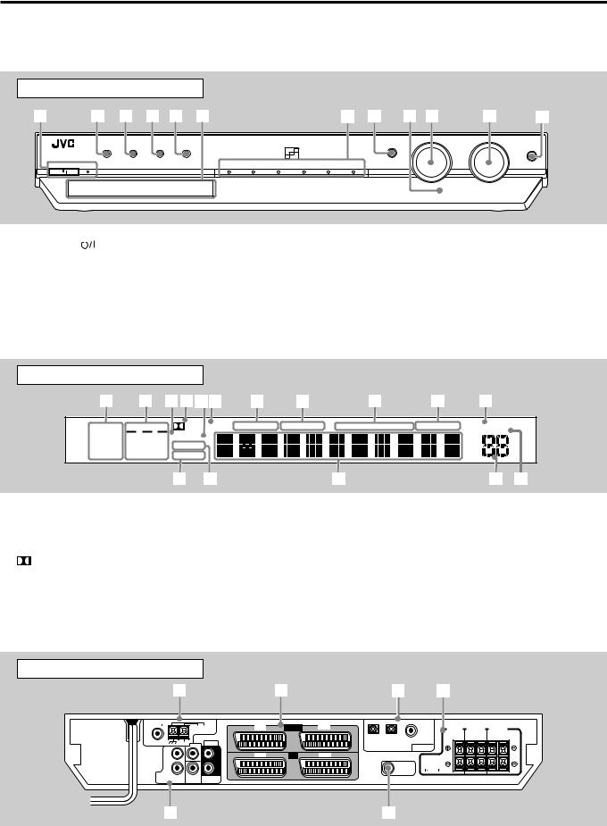
Front panel
1 |
2 3 4 5 6 |
7 8 9 p |
q |
w |
|
|
|
|
|
|
|
|
|
|
SOURCE SELECTOR |
MASTER VOLUME |
|
TV DIRECT |
SETTING |
ADJUST |
SURROUND |
|
|
|
|
SET / TUNER PRESET |
MULTI JOG |
|
|
|
|
|
|
|
PHONES |
|||||
|
|
|
|
|
|
|
|
|
|
|
|
STANDBY / ON |
STANDBY |
|
|
DVD MULTI |
DVD |
STB |
VCR |
TV |
FM / AM |
|
|
1 |
STANDBY/ON |
|
button and STANDBY lamp (11) |
8 |
• |
SET button (16, 17, 19, 21, 31, 33, 34) |
2 |
TV DIRECT button (13) |
|
• |
TUNER PRESET button (24) |
||
3 |
SETTING button (16, 17, 19) |
9 |
Remote sensor (5) |
|||
4 |
ADJUST button (21, 31, 33, 34) |
p SOURCE SELECTOR (11) |
||||
5 |
SURROUND button (31, 33) |
|
MULTI JOG (16, 17, 19, 21, 31 – 34) |
|||
6 |
Display window (see below) |
q MASTER VOLUME control (12) |
||||
7 |
Source indicators |
w PHONES jack (12) |
||||
|
DVD MULTI, DVD, STB, VCR, TV, FM/AM |
|
|
|
||
Display window |
|
|
|
|
|
|
|
|
|
|
|
1 |
2 3456 |
7 |
8 |
|
9 |
p |
|
q |
|||
ANALOG |
L C |
R |
PLΙΙ |
SLEEP AUTO MODE BASS BOOST |
TA |
NEWS INFO RDS TUNED |
ST |
AUTO MUTING |
|||
LPCM |
SUBWFR LFE DSP HP |
|
|
|
|
|
|
|
A.POSITION |
||
|
|
|
|
|
|
|
MHZ |
||||
DOLBY D |
LS S |
RS |
AUTO SR |
|
|
|
|
|
|
|
kHZ |
DTS |
INPUT ATT |
|
|
|
|
|
|
VOL |
|||
|
|
|
w |
e |
|
|
r |
|
|
|
t y |
1 |
Signal format indicators (11, 13) |
p Tuner operation indicators (23) |
|
ANALOG, LPCM (Linear PCM), DOLBY D (Dolby Digital), DTS |
TUNED, ST (stereo) |
2 |
Signal and speaker indicators (14) |
q AUTO MUTING indicator (24) |
3 |
DSP indicator (29, 32, 33) |
w INPUT ATT (attenuator) indicator (22) |
4 |
PL II indicator (28) |
e AUTO SR (surround) indicator (20) |
5 |
HP (headphone) indicator (12) |
r Main display |
6 |
SLEEP indicator (14) |
t Volume level indicator (11) |
7 |
AUTO MODE indicator (20) |
y A (audio).POSITION indicator (22) |
8 |
BASS BOOST indicator (22) |
|
9RDS operation indicators (25, 27)
TA, NEWS, INFO, RDS
Rear panel
1 |
2 |
3 |
4 |
FM 75 |
AM LOOP |
VCR |
IN / OUT |
TV |
DIGITAL 1 |
CENTER |
|
||||||
|
ANTENNA |
|
|
|
(DVD) |
SPEAKER |
SURROUND FRONT SPEAKERS SPEAKERS
RIGHT LEFT RIGHT LEFT
COAXIAL |
AM EXT |
AUDIO |
DIGITAL 3 |
DIGITAL 2 |
|
|
CENTER |
|
DIGITAL IN |
||
|
|
|
(TV) |
(STB) |
|
L |
|
|
|
|
R |
|
|
|
DVD |
|
SUB |
SURR |
|
IN |
FRONT |
|||
WOOFER |
(REAR) |
|||
|
5
L |
DVD |
AV IN |
STB |
CAUTION: |
|
|
|||||
|
|
|
|
||
|
|
|
|
SPEAKER |
|
R |
|
|
SUBWOOFER |
IMPEDANCE |
|
|
|
OUT |
8 |
~ 16 |
|
|
|
|
|||
6
1 |
ANTENNA terminals (6) |
4 |
Speaker terminals (7) |
|
2 |
SCART terminals (9) |
|
FRONT SPEAKERS, SURROUND SPEAKERS, CENTER |
|
|
AV IN/OUT (VCR, TV), AV IN (DVD, STB) |
|
SPEAKER |
|
3 |
DIGITAL IN terminals (8) |
5 |
DVD IN jacks (10) |
|
|
DIGITAL 1 (DVD) , DIGITAL 2 (STB), DIGITAL 3 (TV) |
|
FRONT, CENTER, SURR (REAR), SUBWOOFER |
3 |
|
|
6 |
SUBWOOFER OUT jack (7) |
|
|
|
|

Parts identification |
|
|
|
|
|
|
XV-N55SL |
|
|
|
|
|
|
See pages in parentheses for details. |
|
|
|
|
|
|
|
Front panel |
|
|
|
|
|
1 |
2 3 |
4 |
5 |
6 7 8 |
9 0 |
- |
|
/ ON |
|
|
|
|
|
1 |
|
|
button (36) |
|
|
|
|
7 |
4 button (39, 40) |
|
|
|
|||||
2 |
STANDBY/ON indicator (36) |
|
|
|
|
8 |
¢ button (39, 40) |
|
|
|
|||||||
3 |
Display window |
|
|
|
|
9 |
7 button (37, 38) |
|
|
|
|||||||
4 |
Remote sensor (5) |
|
|
|
|
0 |
3 button (37, 39) |
|
|
|
|||||||
5 |
Disc tray (37) |
|
|
|
|
|
- 8 button (38, 39) |
|
|
|
|||||||
6 |
0 button (37) |
|
|
|
|
|
|
|
|
|
|
|
|
|
|||
|
|
|
|
|
|
|
|
|
|
|
|
|
|
|
|
|
|
|
|
|
Display window |
|
|
|
|
|
|
|
|
|
|
|
|
|
|
|
1 |
2 |
|
|
3 |
4 |
5 |
6 |
|
||||||||
|
|
|
|
|
|
|
|
|
|
|
|
|
|
|
|
|
|
|
|
|
|
|
|
|
|
|
|
|
|
|
|
|
|
|
|
|
|
|
|
|
|
|
|
|
|
|
|
|
|
|
|
|
|
|
|
|
|
|
|
|
|
|
|
|
|
|
|
|
|
|
|
|
|
|
|
|
|
|
|
|
|
|
|
|
|
|
|
|
|
|
|
|
|
|
|
|
|
|
|
|
|
|
|
|
|
|
|
|
|
|
|
|
|
|
|
|
|
|
|
|
|
|
|
|
|
|
7 |
8 9 |
|
|
|
|
|
0 |
|||
1 |
Audio format indicators |
|
6 |
Total time/remaining time indicators |
|
2 |
Disc indicator |
|
7 |
3D indicator |
|
3 |
Group/title/track/chapter indicators |
|
8 |
3 (play)/8 (pause) indicators |
|
4 |
Repeat mode indicator |
|
9 |
Resume indicator |
|
5 |
Program/random indicators |
|
0 |
Multi-information window |
|
Rear panel
1 2 3
LEFT |
COAXIAL |
VIDEO |
PCM/ STREAM
RIGHT |
OPTICAL |
S-VIDEO |
AUDIO OUT |
DIGITAL OUT |
VIDEO OUT |
4 5 6
|
VIDEO SIGNAL |
AV OUT |
SELECTOR |
|
RGB/ COMP. |
|
Y/ C |
|
AV COMPU |
1 AUDIO OUT LEFT/RIGHT jacks*1
2DIGITAL OUT jacks (9) COAXIAL, OPTICAL
3VIDEO OUT jacks*2
VIDEO, S-VIDEO
4 SCART terminal (9)
AV OUT
5 VIDEO SIGNAL SELECTOR (9)
6 AV COMPU LINK (for future use)
NOTES
*1 This jack is not used with this unit. They are used when the player is connected directly to a TV and the like.
*2 These jacks are not used with this unit. They are used when the player is connected directly to a TV and the like.
Use only one type of video jack—composite video, S-video, SCART —when connecting the DVD player. Using multiple jacks will make color and brightness show incorrectly on the display.
4
Getting started
Precautions
General precautions
•DO NOT disassemble the unit or remove screws, covers, or cabinet.
•DO NOT expose the unit to rain or moisture.
•DO NOT expose the unit to direct sunlight or place it near a heating device.
Locations
•Install the receiver in a location that is level and protected from moisture and dust.
If water gets inside the unit, turn off the power and remove the plug from the outlet, then consult your dealer. Using the unit in this state may cause a fire or electrical shock.
•Select a place which is level, dry and neither too hot nor too cold between 5˚C and 35˚C
•Make sure there is good ventilation around the receiver. Poor ventilation could cause overheating and damage the receiver.
•Leave sufficient distance between the unit and the TV.
•Do not install the unit in a place subject to vibrations.
Handling the receiver
•DO NOT touch the power cord with wet hands.
•DO NOT pull on the power cord to unplug the cord. When unplugging the cord, always grasp the plug so as not to damage the cord.
•Keep the power cord away from the connecting cords and the antenna. The power cord may cause noise or screen interference. It is recommended to use a coaxial cable for antenna connection, since it is well-shielded against interference.
•When a power failure occurs, or when you unplug the power cord, the preset settings such as preset FM or AM (MW) channels and sound adjustments may be erased in a few days.
•When you are away on travel or otherwise for an extended period or time, remove the plug from the wall outlet. A small amount of power is always consumed while the power cord is connected to the wall outlet.
To prevent the malfunction
•There are no user-servicable parts inside. If anything goes wrong, unplug the power cord and consult your dealer.
•Do not insert any metallic objects, such as wires, hairpins, coins, etc, into the unit.
•Do not block the vents. Blocking the vents may damage the unit.
To clean the cabinet
•Use a soft cloth. Follow the relevant instructions on the use of chemically-coated cloths.
•Do not use benzene, thinner or other organic solvents and disinfectants. These may cause deformation or discoloring.
Checking the supplied accessories
Check to be sure you have all of the following supplied accessories. The number in parentheses indicates the quantity of each piece supplied.
•Remote control (1)
•Batteries (2)
•AM (MW) loop antenna (1)
•FM antenna (1)
•SCART cable (1)
•Digital coaxial cord (1)
If anything is missing, contact your dealer immediately.
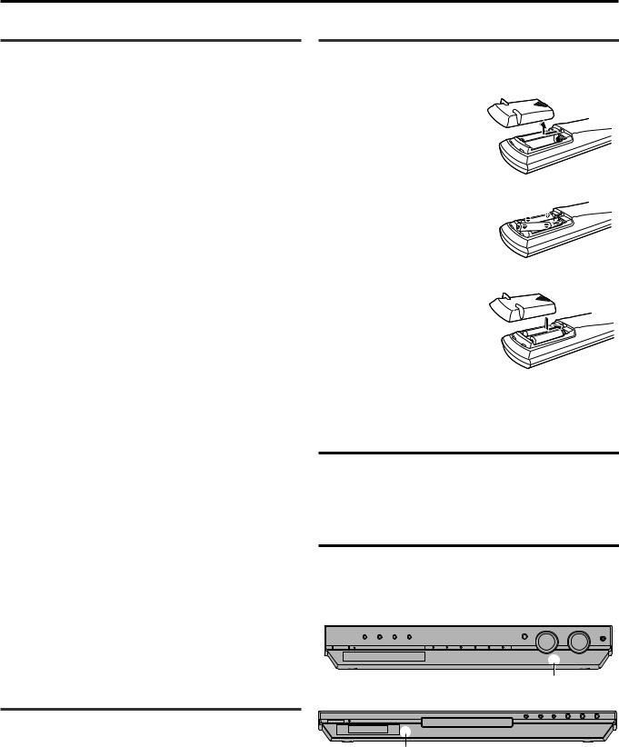
Putting batteries in the remote control
Before using the remote control, put two supplied batteries first.
1 Press and slide the buttery cover on the bac k of the remote control.
2 Insert batteries.
Make sure to match the polarity:
(+) to (+) and (–) to (–).
3 Replace the co ver.
If the range or effectiveness of the remote control decreases, replace the batteries. Use two R6P(SUM-3)/AA(15F) type dry-cell batteries.
• Supplied butteries are for initial setup. Replace for continued use.
CAUTION:
Follow these precautions to avoid leaking or cracking cells:
•Place batteries in the remote control so they match the polarity:
(+) to (+) and (–) to (–).
•Use the correct type of batteries. Batteries that look similar may differ in voltage.
•Always replace both batteries at the same time.
•Do not expose batteries to heat or flame.
When using the remote control, aim the remote control directly at the remote sensor on the front panel.
RX-ES1SL
Remote sensor
XV-N55SL
Remote sensor
5
Getting started
Connecting the FM and AM (MW) antennas
If FM reception is poor, connect outdoor FM antenna (not supplied).
If AM (MW) reception is poor, connect an outdoor single vinyl-covered wire (not supplied).
1 |
2 |
3 |
AM (MW) loop antenna (supplied)
Snap the tabs on the loop into the slots of the base to assemble the AM (MW) loop antenna.
FM antenna (supplied)
FM 75 |
AM LOOP |
|
ANTENNA
COAXIAL
75 FM
COAXIAL
FM 75 |
|
AM LOOP |
VCR |
AV IN / OUT |
TV |
|
DIGITAL 1 |
CENTER |
SURROUND |
FRONT |
|
|
|
||||||||
|
|
ANTENNA |
|
|
|
|
(DVD) |
SPEAKER |
SPEAKERS |
SPEAKERS |
|
|
|
|
|
|
|
|
|
RIGHT LEFT |
RIGHT LEFT |
COAXIAL |
AM EXT |
AUDIO |
|
|
DIGITAL 3 |
DIGITAL 2 |
|
|
|
|
|
|
CENTER |
|
|
DIGITAL IN |
|
|
|
||
|
|
|
|
|
(TV) |
(STB) |
|
|
|
L
R
DVD |
|
SUB |
SURR |
|
IN |
FRONT |
|||
WOOFER |
(REAR) |
L |
DVD |
AV IN |
STB |
CAUTION: |
|
|
|||||
|
|
|
|
||
|
|
|
|
SPEAKER |
|
R |
|
|
SUBWOOFER |
IMPEDANCE |
|
|
|
OUT |
8 |
~ 16 |
|
|
|
|
|||
RX-ES1SL
AM (MW) antenna connection |
NOTES |
Connect the AM (MW) loop antenna supplied to the AM LOOP terminals.
Connect the white cord to the AM EXT terminal, and the black cord to H terminal.
Turn the loop until you have the best reception.
•If the reception is poor, connect an outdoor single vinyl-covered wire (not supplied) to the AM EXT terminal. Keep the AM (MW) loop antenna connected.
•If the AM (MW) loop antenna wire is covered with vinyl, remove the vinyl while twisting it as shown on the right.
•Make sure the antenna conductors do not touch any other terminals, connecting cords and power cord.
This could cause poor reception.
FM antenna connection
Connect the FM antenna supplied to the FM 75 Ω COAXIAL terminal as temporary measure.
Extend the supplied FM antenna horizontally.
•If the reception is poor, connect an outdoor FM antenna (not supplied). Before attaching a 75 Ω coaxial cable with a connector (IEC or DIN 45325), disconnect the supplied FM antenna.
6
Getting Started
Connecting the speakers and DVD player
Turn off all components before connections.
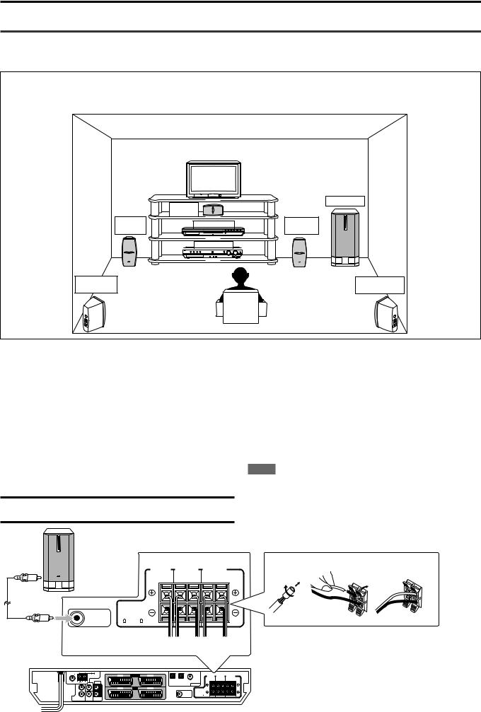
Speaker Layout Diagram
After connecting the front, center and surround speakers, and/or a subwoofer, set the speaker setting information properly to obtain the best possible surround effect. For details, see pages 15 to 18.
|
Center |
Subwoofer |
|
|
|
||
|
speaker |
|
|
Left front |
XV-N55SL |
Right front |
|
speaker |
speaker |
||
|
|||
|
RX-ES1SL |
|
|
Left surround |
|
Right surround |
|
speaker |
|
speaker |
Connecting the front, center, and surround speakers
For each speaker, connect the (+) and (–) terminals on the rear panel to the (+) and (–) terminals marked on the speakers respectively.
1Twist and remove the insulation at the end of each speaker cord (not supplied).
2Press and hold the clamp of the speaker terminal (1), then insert the speaker cord (2).
3Release the finger from the clamp.
CAUTION:
Use speakers with the SPEAKER IMPEDANCE indicated by the speaker terminals.
Powered subwoofer |
|
|
|
|
CENTER |
SURROUND |
FRONT |
|
SPEAKER |
SPEAKERS |
SPEAKERS |
|
|
RIGHT LEFT |
RIGHT LEFT |
|
CAUTION: |
|
|
|
SPEAKER |
|
|
SUBWOOFER |
IMPEDANCE |
|
|
OUT |
8 ~ 16 |
|
|
Connecting the subwoofer
By connecting a subwoofer, you can enhance the bass or reproduce the original LFE signals recorded in the digital software.
Connect the input jack of a powered subwoofer to the SUBWOOFER OUT jack on the rear panel, using a cord with RCA pin plugs (not supplied).
• Refer also to the manual supplied with your subwoofer.
NOTE
You can place a subwoofer wherever you like since bass sound is non-directional. Normally place it in front of you.
1 |
2 |
3 |
|
2 |
1 |
AB CD E
|
AM LOOP |
VCR |
AV IN / OUT |
TV |
|
DIGITAL 1 |
CENTER |
SURROUND |
FRONT |
|
|
ANTENNA |
|
|
|
|
(DVD) |
SPEAKER |
SPEAKERS |
SPEAKERS |
|
|
|
|
|
|
|
|
|
|
RIGHT LEFT |
RIGHT LEFT |
COAXIAL |
AM EXT CENTER |
AUDIO |
|
|
DIGITAL 3 |
DIGITAL 2 |
|
|
|
|
|
|
|
DIGITAL IN |
|
|
|
||||
|
|
|
|
|
(TV) |
(STB) |
|
|
|
|
L |
L |
DVD |
AV IN |
STB |
|
|
|
|
|
|
|
CAUTION: |
|
|
|
|
|
|
SPEAKER |
|
R |
R |
|
|
SUBWOOFER |
IMPEDANCE |
|
|
|
|
|
OUT |
8 |
~ 16 |
DVD |
|
SUB |
SURR |
IN |
FRONT |
||
|
WOOFER |
(REAR) |
RX-ES1SL
A To center speaker
B To right surround speaker
C To left surround speaker
D To right front speaker
E To left front speaker
CONTINUED ON THE NEXT PAGE
7

Getting started
FM 75 |
AM LOOP |
VCR |
AV IN / OUT |
TV |
|
DIGITAL 1 |
CENTER |
SURROUND |
FRONT |
|
|
ANTENNA |
|
|
|
|
(DVD) |
SPEAKER |
SPEAKERS |
SPEAKERS |
|
|
|
|
|
|
|
|
|
|
RIGHT LEFT |
RIGHT LEFT |
COAXIAL |
AM EXT CENTER |
AUDIO |
|
|
DIGITAL 3 |
DIGITAL 2 |
|
|
|
|
|
|
|
DIGITAL IN |
|
|
|
||||
|
|
|
|
|
(TV) |
(STB) |
|
|
|
|
L |
L |
DVD |
AV IN |
STB |
|
|
|
CAUTION: |
|||
|
|
|
|
|
SPEAKER |
|
|
|
|
SUBWOOFER |
IMPEDANCE |
Connecting the DVD player (XV-N55SL)
Connect the DVD player by using a SCART cable and/or a digital cord.
•To enjoy the digital sound, digital connection is required—Digital optical connection or Digital coaxial connection.
|
|
|
|
DIGITAL 1 |
DVD |
AV IN |
STB |
|
(DVD) |
|
|
|||
|
|
DIGITAL 3 |
DIGITAL 2 |
DIGITAL IN |
|
|
(TV) |
(STB) |
Before connecting an optical digital cord, unplug the protective plug.
Digital |
|
Digital |
|
||
optical cord |
|
coaxial cord |
|
||
(not supplied) |
|
(supplied: 1 |
|
||
SCART |
|
|
|
cable) |
|
|
|
|
|
|
|
cable |
|
COAXIAL |
|
|
|
(supplied: |
|
PCM/ |
STREAM |
AV OUT |
|
1 cable) |
|
OPTICAL |
|
|
|
|
DIGITAL OUT |
|
|
||
|
|
|
|
||
|
|
|
|
|
VIDEO SIGNAL |
LEFT |
|
|
|
AV OUT |
SELECTOR |
|
|
|
|
|
RGB/ COMP. |
|
PCM/ STREAM |
|
|
|
Y/ C |
RIGHT |
OPTICAL |
S-VIDEO |
|
|
AV COMPU LINK |
AUDIO OUT |
DIGITAL OUT |
VIDEO OUT |
|
|
|
XV-N55SL
NOTES
•When shipped from the factory, the DIGITAL IN terminals have been set for use with the following components:
–DIGITAL 1 (coaxial): For DVD player
–DIGITAL 2 (optical): For STB (Set Top Box)
–DIGITAL 3 (optical): For TV tuner
If you connect other components, change the digital input (DIGITAL IN) terminal setting correctly. See “Setting the digital input (DIGITAL IN) terminals—DIGITAL IN” on page 19.
•Select the correct digital input mode.
See “Selecting the analogue or digital input mode” on page 11.
Set the VIDEO SIGNAL SELECTOR correctly according to your TV.
• If your TV only accomodates the composite video signal, set the VIDEO SIGNAL SELECTOR to “RGB/COMP.”
•If your TV only accomodates the Y/C signal, set the selector to “Y/C,” so that you can enjoy better-quality picture.
•If your TV accomodates the RGB signal, set the VIDEO SIGNAL SELECTOR to “RGB/COMP.”
Connecting other video components
Turn off all components before making connections.
•Illustrations of the input/output terminals are typical examples.
When you connect other components, refer also to their manuals since the terminal names actually printed on the rear vary among different components.
CAUTION:
If you connect a sound-enhancing device such as a graphic equalizer between the source components and this receiver, the sound output through this receiver may be distorted.
Digital connection
|
|
DIGITAL 1 |
|
|
(DVD) |
DIGITAL 3 |
DIGITAL 2 |
DIGITAL IN |
(TV) |
(STB) |
RX-ES1SL
VCR |
AV IN /OUT |
TV |
|
|
DIGITAL 1 |
CENTER |
SURROUND |
FRONT |
|
|
|
|
|
(DVD) |
SPEAKER |
SPEAKERS |
SPEAKERS |
|
|
|
|
|
|
|
RIGHT LEFT |
RIGHT LEFT |
|
|
DIGITAL 3 |
DIGITAL 2 |
DIGITAL IN |
|
|
|
|
|
|
(TV) |
(STB) |
|
|
|
||
DVD |
AV IN |
STB |
|
|
CAUTION: |
|
|
|
|
|
|
|
|
SPEAKER |
|
|
|
|
|
|
SUBWOOFER |
IMPEDANCE |
|
|
|
|
|
|
|
|
OUT |
8 ~ 16 |
|
|
|
Before connecting an optical digital cord, unplug the protective plug.
TV
OPTICAL
DIGITAL OUT
Digital optical cord (not supplied)
Digital coaxial cord
(supplied: 1 cable) COAXIAL STB (Set Top Box)
DIGITAL OUT
NOTES
•When shipped from the factory, the DIGITAL IN terminals have been set for use with the following components:
–DIGITAL 1 (coaxial): For DVD player
–DIGITAL 2 (optical): For STB (Set Top Box)
–DIGITAL 3 (optical): For TV tuner
If you connect other components, change the digital input (DIGITAL IN) terminal setting correctly. See “Setting the digital input (DIGITAL IN) terminals—DIGITAL IN” on page 19.
•Select the correct digital input mode.
See “Selecting the analogue or digital input mode” on page 11.
8
Getting started
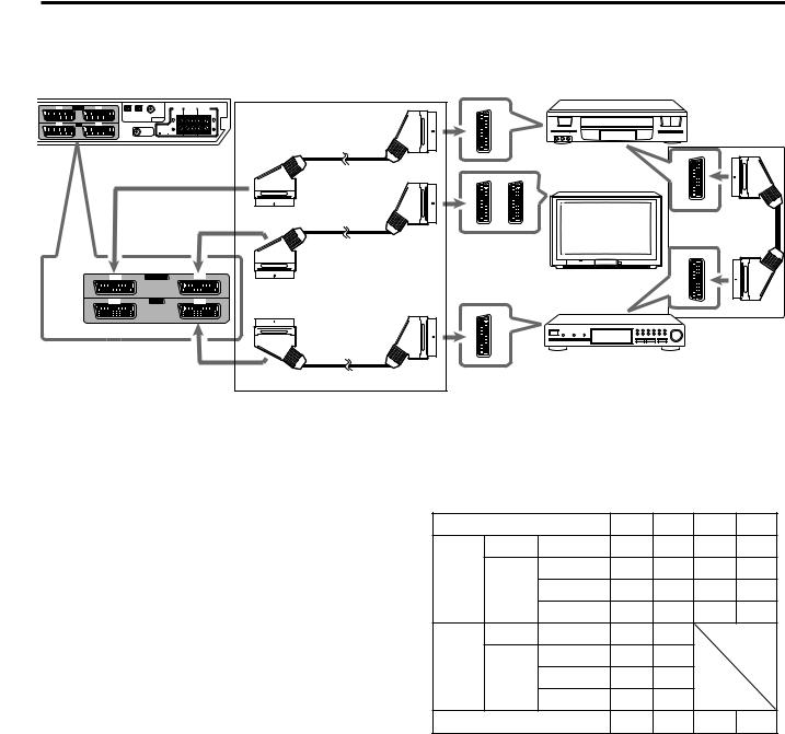
SCART connection
|
|
|
|
|
|
|
|
|
|
|
|
SCART cable (supplied: 1 cable) |
VCR |
|
AM LOOP |
|
VCR |
AV IN / OUT |
TV |
|
|
DIGITAL 1 |
CENTER |
SURROUND |
FRONT |
|
|
|
ANTENNA |
|
|
|
|
|
|
(DVD) |
SPEAKER |
SPEAKERS |
SPEAKERS |
|
|
|
|
|
|
|
|
|
|
|
|
|
RIGHT LEFT RIGHT LEFT |
|
|
AM EXT |
CENTER |
AUDIO |
|
|
|
DIGITAL 3 |
DIGITAL 2 |
DIGITAL IN |
|
|
|
|
|
|
|
|
|
|
|
(TV) |
(STB) |
|
|
|
|
||
L |
|
|
L |
DVD |
AV IN |
STB |
|
|
|
|
|
|
|
|
|
|
|
|
|
|
|
|
CAUTION: |
|
|
|
|
|
|
|
|
|
|
|
|
|
SPEAKER |
|
|
|
|
R |
|
|
R |
|
|
|
SUBWOOFER |
IMPEDANCE |
|
|
|
|
|
D |
|
|
|
|
|
|
|
OUT |
8 ~ 16 |
|
|
|
|
SUB |
SURR |
|
|
|
|
|
|
|
|
|
|
|
|
FRONT |
|
|
|
|
|
|
|
|
|
|
|
||
WOOFER |
(REAR) |
|
|
|
|
|
|
|
|
|
|
|
|
RX-ES1SL
TV
VCR |
AV IN/OUT |
TV |
DVD |
AV IN |
STB |
STB |
*
See below.
For TV and video format
•When the TV is equipped with the multiple SCART terminals, refer to the TV manual to check the available video signals for each terminal, then connect SCART cable correctly.
•This receiver cannot convert the video signals (S-video or
Composite). When the video signal of one video component is different from that of the other (for example, one is S-video, the other is Composite), you may not see the pictures appropriately. In this case, unify the video signals of all the video components into
S-video or Composite, or you need to switch the video signal of TV each time you change the source.
For T-V LINK
•You can use the T-V LINK function if you connect a T-V LINK compatible TV and VCR to this receiver with a fully wired SCART cables. For details on T-V LINK, refer also to the manuals supplied with the TV and the VCR.
•Connect a SCART cable to EXT-2 terminal on your JVC’s T-V LINK compatible TV for the T-V LINK function.
•Some TV, VCR, STB and DVD players’ support the data communication like T-V LINK. For complete details, refer also to the manuals supplied with these components.
* For an analogue decoder
To watch or record a scrambled program on your VCR, connect the analogue decoder to your VCR and select the scrambled channel on your VCR.
If there is not an appropriate terminal for the decoder connection on your VCR, connect the decoder to your TV.
Refer also to the manuals supplied with these components.
* For recording pictures from STB
When you connect a STB and a VCR directly with a SCART cable, you can record the pictures from the STB onto VCR without using the STB menu screens. For details, refer also to the manuals supplied with the STB.
For digital sounds
To reproduce the digital sound, use both the digital connection and the SCART cable connection (see pages 8 and 9).
SCART Terminal Specifications
|
|
TV |
VCR |
STB |
DVD |
AUDIO |
L/R |
|
|
|
|
IN |
Composite |
|
|
|
|
|
− |
|
|
|
|
VIDEO |
S-video |
|
|
|
|
|
RGB |
− |
|
|
|
AUDIO |
L/R |
*1 |
*1 |
|
|
OUT |
Composite *1*2 *1*2 |
|
|
||
|
|
− |
|
|
|
VIDEO |
S-video |
*2 |
|
|
|
|
RGB |
*2 |
− |
|
|
T-V LINK |
|
*3 |
*3 |
*3 |
*3 |
*1 The signals input from a SCART terminal cannot be output through the same SCART terminal.
*2 The video format of the output video signals are consistent with that of the input video signals. For example, if S-video signals are input to this receiver, no signals other than S-video signals can be output from this receiver.
Refer to the manuals supplied with the video components to check the setting of the input/output video signals.
*3 The signals for the T-V LINK function are always going through the receiver.
CONTINUED ON THE NEXT PAGE
9

Getting started
Analogue connection for DVD MULTI playback (see page 34)
• DVD MULTI playback is not available for XV-N55SL.
RX-ES1SL
FM 75 |
AM LOOP |
VCR |
AV IN / OUT |
TV |
|
DIGITAL 1 |
CENTER |
SURROUND |
FRONT |
|
|
|
|||||||||
|
ANTENNA |
|
|
|
|
(DVD) |
SPEAKER |
SPEAKERS |
SPEAKERS |
|
|
|
|
|
|
|
|
|
|
RIGHT LEFT |
RIGHT LEFT |
COAXIAL |
AM EXT CENTER |
AUDIO |
|
|
DIGITAL 3 |
DIGITAL 2 |
|
|
|
|
|
|
|
DIGITAL IN |
|
|
|
||||
|
|
|
|
|
(TV) |
(STB) |
|
|
|
|
L |
L |
DVD |
AV IN |
STB |
|
|
|
|
CAUTION: |
||||
|
|
|
|
|
SPEAKER |
|
R |
R |
|
|
SUBWOOFER |
IMPEDANCE |
|
|
|
|
|
OUT |
8 |
~ 16 |
DVD |
|
SUB |
SURR |
IN |
FRONT |
||
|
WOOFER |
(REAR) |
DVD Player (ex. XV-NA7SL)
Monaural audio cord
(not supplied)
 To center channel audio output
|
|
CENTER |
AUDIO |
|
|
L |
|
L |
|
|
|
|
||
|
R |
|
R |
|
DVD |
|
SUB |
SURR |
|
IN |
FRONT |
|||
WOOFER |
(REAR) |
|||
|
Stereo audio cord (not supplied)
To surround left channel audio output

 To surround right channel audio Monaural audio cord output
(not supplied)
 To subwoofer output
To front right channel audio output


 To front left channel audio output Stereo audio cord (not supplied)
NOTE
When using the DVD MULTI playback, use the same DVD player connected to this receiver by a SCART cable. If you connect a different DVD player, the mixed sound from front left and right channels are reproduced.
Connecting the power cord
When all the audio/video connections have been made, connect the AC power plug to the wall outlet. Make sure that the plugs are inserted firmly. The STANDBY lamp on the receiver and indicator on the DVD player light in red.
• Keep the power cord away from the connecting cables and the antenna. The power cord may cause noise or screen interference.
NOTES
•The preset settings such as preset channels and sound adjustment may be erased in a few days in the following cases:
–when you unplug the power cord.
–when a power failure occurs.
•Disconnect the power cord:
–if you are not going to use the player for a long period of time.
–before cleaning the player.
–before moving the player.
•Do not:
–connect or disconnect the power cord with wet hands.
–pull the power cord when disconnecting it, as this may damage the cord and cause fire, electric shock, or other accidents.
CAUTIONS:
•Do not touch the power cord with wet hands.
•Do not alter, twist or pull the power cord, or put anything heavy on it, which may cause fire, electric shock, or other accidents.
•If the cord is damaged, consult a dealer and have the power cord replaced with a new one.
10

RX-ES1SL
Basic operations
|
|
|
|
|
|
|
|
|
|
|
SOURCE SELECTOR |
MASTER VOLUME |
|
TV DIRECT SETTING |
ADJUST |
SURROUND |
|
|
|
|
SET / TUNER PRESET |
MULTI JOG |
|
||
|
|
|
|
|
|
|
|
|
|
|
|
PHONES |
STANDBY / ON |
STANDBY |
|
|
|
DVD MULTI |
DVD |
STB |
VCB |
TV |
FM / AM |
|
|
|
HOME CINEMA CONTROL CENTER |
|
|
|
|
|
|
|
||||
|
TV DIRECT |
|
|
|
AUDIO |
|
|
|
|
|
|
|
|
DVD |
|
VCR |
STB |
TV |
|
|
|
|
|
|
|
|
DVD |
|
VCR |
STB |
TV |
|
|
|
|
|
|
|
|
DVD MULTI |
FM/AM |
TV/VIDEO MUTING |
|
|
|
|
|
|
|
||
|
TV VOL |
CHANNEL |
VOLUME |
|
When operating the receiver |
|||||||
|
|
|
|
|
DVD |
|
using the remote control, |
|
||||
|
|
|
|
|
AUDIO/TV |
|
|
|||||
|
|
|
|
|
/VCR/STB |
|
always set the mode selector |
|||||
|
TUNING |
FM MODE |
TUNING |
|
||||||||
|
|
to AUDIO/TV/VCR/STB. |
|
|||||||||
|
|
MEMORY |
|
|
|
|
||||||
|
TOP MENU |
|
TA/NEWS/INFO |
MENU |
|
|
|
|
|
|
|
|
|
PTY |
|
ENTER |
PTY |
|
|
|
|
|
|
|
|
|
CHOICE |
|
|
|
ON |
|
|
|
|
|
|
|
|
|
|
|
SCREEN |
|
|
|
|
|
|
|
|
|
|
|
PTY SEARCH |
DISPLAY |
|
|
|
|
|
|
|
|
|
|
|
|
|
|
|
|
|
|
|
||
|
AUDIO |
SUBTITLE TITLE/GROUP RETURN |
|
|
|
|
|
|
|
|||
|
ZOOM |
|
|
BASS |
TREBLE |
|
|
|
|
|
|
|
|
|
|
1 |
2 |
3 |
|
|
|
|
|
|
|
|
|
|
|
BASS |
TREBLE |
|
|
|
|
|
|
|
|
VFP |
|
4 |
5 |
6 |
|
|
|
|
|
|
|
|
|
|
7 |
8 |
9 |
|
|
|
|
|
|
|
|
ANGLE |
TV RETURN |
|
100+ |
|
|
|
|
|
|
|
|
|
|
|
10 |
0 |
+10 |
|
|
|
|
|
|
|
|
REPEAT |
|
|
|
|
|
|
|
|
|
|
|
|
|
|
3D |
|
|
|
|
|
|
|
|
|
|
DIMMER |
|
SLEEP ANALOG/DIGITAL CANCEL |
|
|
|
|
|
|
|
||
|
|
|
|
INPUT |
|
|
|
|
|
|
|
|
|
SMART S. SETUP BASS BOOST |
|
.POSITION |
|
|
|
|
|
|
|
||
|
|
|
|
TONE |
|
|
|
|
|
|
|
|
|
|
|
|
|
SURROUND |
|
|
|
|
|
|
|
|
TEST |
|
EFFECT |
DECODE |
|
|
|
|
|
|
|
|
|
SUBWFR |
CENTER |
L SURR R |
|
|
|
|
|
|
|
||
2 Select the source to play
On the front panel:
Turn SOURCE SELECTOR until the source name you want appears on the display.
The source indicator corresponding to the selected source lights in red.
• As you turn SOURCE SELECTOR, the source changes as follow:
ANALOG L C |
|
R |
|
||||
|
|
|
|
|
|
|
|
SUBWFR LFE |
|
||||||
|
LS |
|
RS |
VOL |
|||
|
|
|
|
|
|
|
|
DVD MULTI
 DVD (DVD DIGITAL)

STB (STB DIGITAL) VCR
VCR TV (TV DIGITAL)
 FM
FM
 AM
AM 
 (Back to the beginning)
From the remote control:
Press one of the source selecting buttons.
•Each time you press FM/AM, FM and AM (MW) changes alternately.
DVD MULTI: |
Select the DVD player using the analogue |
|
discrete output mode (5.1 channel reproduction). |
DVD (DIGITAL)*: |
To enjoy the DVD MULTI playback see page 34. |
Select the DVD player. |
|
STB (DIGITAL)*: |
Select the STB. |
VCR: |
Select the VCR. |
TV (DIGITAL)*: |
Select the TV tuner. |
FM: |
Select an FM broadcast. |
AM: |
Select an AM (MW) broadcast. |
1 Turn on the power
Press STANDBY/ON  (or
(or  AUDIO on the remote control).
The STANDBY lamp goes off. The current source indicator lights in red. The name of the current source (or station frequency) appears on the display.
|
|
|
|
|
|
|
Current volume level is shown here. |
||
|
|
|
|
|
|
|
|
|
|
ANALOG L C |
|
R |
|
|
|
||||
|
|
|
|
|
|
|
|
|
|
SUBWFR LFE |
|
|
|
||||||
|
LS |
|
RS |
VOL |
|
||||
|
|
|
|
|
|
|
|
|
|
Current source name appears.
To turn off the power (into standby)
Press STANDBY/ON  again (or
  AUDIO on the remote control). The STANDBY lamp lights up.
NOTE
A small amount of power is consumed in standby mode. To turn the power off completely, unplug the AC power cord.
* Selecting the analogue or digital input mode
When you have connected the DVD player, STB, or TV tuner using both the analogue connection and the digital connection methods (see pages 8 and 9), you need to select the correct input mode.
•You can select the digital input only for sources which you have selected digital input terminals for. (See “Setting the digital input
(DIGITAL IN) terminals—DIGITAL IN” on page 19.)
From the remote control ONLY:
Press ANALOG/DIGITAL INPUT to select the analogue or digital input mode.
•Each time you press the button, the input mode alternates between the analogue input (“ANALOGUE”) and the digital input (“DGTL
AUTO”).
DGTL AUTO: Select for the digital input mode. The receiver automatically detects the incoming signal format, then the digital signal format indicator (DOLBY D,
DTS or LPCM) for the detected signals lights up.
ANALOGUE*: Select for the analogue input mode.
* Initial setting
NOTE
You cannot select the digital input mode when selecting “DVD MULTI” as the playing source.
11

Basic operations
|
|
|
|
|
|
|
|
|
|
|
SOURCE SELECTOR |
MASTER VOLUME |
|
TV DIRECT |
|
SETTING |
ADJUST |
SURROUND |
|
|
|
|
SET / TUNER PRESET |
MULTI JOG |
|
|
|
|
|
|
|
|
PHONES |
|||||
STANDBY / ON |
STANDBY |
|
|
|
DVD MULTI |
DVD |
STB |
VCB |
TV |
FM / AM |
|
|
|
HOME CINEMA CONTROL CENTER |
|
|
|
|
|
|
|
||||
|
TV DIRECT |
|
|
|
AUDIO |
|
|
|
|
|
|
|
|
DVD |
|
VCR |
STB |
TV |
|
|
|
|
|
|
|
|
DVD |
|
VCR |
STB |
TV |
|
When operating the receiver |
|||||
|
DVD MULTI |
|
FM/AM |
TV/VIDEO MUTING |
|
using the remote control, |
|
|||||
|
TV VOL CHANNEL |
VOLUME |
|
always set the mode selector |
||||||||
|
|
|
|
|
DVD |
|
to AUDIO/TV/VCR/STB. |
|
||||
|
|
|
|
|
AUDIO/TV |
|
|
|||||
|
|
|
|
|
/VCR/STB |
|
|
|
|
|
|
|
|
TUNING |
FM MODE |
TUNING |
|
|
|
|
|
|
|
||
|
|
|
MEMORY |
|
|
|
|
|
|
|
|
|
|
TOP MENU |
|
TA/NEWS/INFO |
MENU |
|
|
|
|
|
|
|
|
|
PTY |
|
ENTER |
PTY |
|
|
|
|
|
|
|
|
|
CHOICE |
|
|
|
ON |
|
|
|
|
|
|
|
|
|
|
|
SCREEN |
|
|
|
|
|
|
|
|
|
|
|
PTY SEARCH |
DISPLAY |
|
|
|
|
|
|
|
|
|
AUDIO |
SUBTITLE TITLE/GROUP RETURN |
|
|
|
|
|
|
|
|||
|
ZOOM |
|
|
BASS |
TREBLE |
|
|
|
|
|
|
|
|
|
|
1 |
2 |
3 |
|
|
|
|
|
|
|
|
|
|
|
BASS |
TREBLE |
|
|
|
|
|
|
|
|
VFP |
|
4 |
5 |
6 |
|
|
|
|
|
|
|
|
|
|
7 |
8 |
9 |
|
|
|
|
|
|
|
|
ANGLE |
TV RETURN |
100+ |
|
|
|
|
|
|
|
||
|
|
|
10 |
0 |
+10 |
|
|
|
|
|
|
|
|
REPEAT |
|
|
|
|
|
|
|
|
|
|
|
|
|
|
3D |
|
|
|
|
|
|
|
|
|
|
DIMMER |
|
SLEEP |
ANALOG/DIGITAL CANCEL |
|
|
|
|
|
|
|
|
|
|
|
|
INPUT |
|
|
|
|
|
|
|
|
|
SMART S. SETUP |
BASS BOOST |
.POSITION |
|
|
|
|
|
|
|
||
|
|
|
|
TONE |
|
|
|
|
|
|
|
|
|
|
|
|
|
SURROUND |
|
|
|
|
|
|
|
|
TEST |
|
EFFECT |
DECODE |
|
|
|
|
|
|
|
|
|
SUBWFR |
|
CENTER |
L SURR R |
|
|
|
|
|
|
|
|
3 Adjust the volume
To increase the volume, turn MASTER VOLUME control clockwise (or press VOLUME + on the remote control).
To decrease the volume, turn MASTER VOLUME control counterclockwise (or press VOLUME – on the remote control).
CAUTION:
Always set the volume to the minimum before starting any sources. If the volume is set at its high level, the sudden blast of sound energy can permanently damage your hearing and/or ruin your speakers.
NOTE
The volume level can be adjusted within the range of “0” (minimum) to “50” (maximum).
Listening with headphones
Connect a pair of headphones to the PHONES jack on the front panel. This cancels the Surround mode currently selected, deactivates speakers, and activates the HEADPHONE mode. The HP (headphone) indicator lights up on the display.
•Disconnecting a pair of headphone from the PHONES jack cancels the HEADPHONE mode and activates the speakers.
HEADPHONE mode
When using the headphones, the following signal is output regardless of your speaker setting:
—For 2 channel sources, the front left and right channel signal is output directly from the left and right headphones.
—For multi-channel sources, the front left and right, center and surround channel signal is down-mixed and then output from the headphones without missing bass element.
You can enjoy multi-channel sound source using the headphones.
CAUTION:
Be sure to turn down the volume:
•Before connecting or putting on headphones, as high volume can damage both the headphones and your hearing.
•Before removing headphones, as high volume may output from the speakers.
Selecting the digital decode mode
If the following symptoms occur while playing Dolby Digital or DTS Digital Surround software with “DGTL AUTO” selected (see page 11), follow the procedure below:
•Sound does not come out at the beginning of playback.
•Noise comes out while searching for or skipping chapters or tracks.
From the remote control ONLY:
1Press ANALOG/DIGITAL INPUT to select “DGTL AUTO.”
2Press DECODE to select “DGTL D.D.” or “DGTL DTS.”
•Each time you press the button, the digital input mode changes as follows:
L |
C |
R |
|
SUBWFR LFE |
|
||
DOLBY D |
|
|
|
LS |
|
RS |
VOL |
DGTL AUTO |
DGTL D.D. |
DGTL DTS
•To play back software encoded with Dolby Digital, select “DGTL
D.D.”
•To play back software encoded with DTS Digital Surround, select “DGTL DTS.”
NOTE
When you turn off the power or select another source, “DGTL DTS” or
“DGTL D.D.” is canceled and the digital input mode is automatically reset to “DGTL AUTO.”
12
Basic operations
The following are the analogue/digital signal format indicators on the display to indicate what type of signal comes into the receiver.
ANALOG: Lights when analogue input is selected.
LPCM: Lights when Linear PCM signal comes in.
DOLBY D: • Lights when Dolby Digital signal comes in.
•Flashes when “DGTL D.D.” is selected for software not encoded with Dolby Digital.
DTS: • Lights when DTS signal comes in.
•Flashes when “DGTL DTS” is selected for software not encoded with DTS.
NOTE
When “DGTL AUTO” cannot recognize the incoming signal, no digital signal format indicator lights up on the display.
To cancel TV Direct and turn off the receiver, press STANDBY/ON  on the front panel.
The receiver is turned off and the STANDBY lamp lights up.
To cancel TV Direct and turn on the receiver, press TV DIRECT on the front panel or  AUDIO on the remote control.
The receiver is turned on and the source indicator currently selected lights in red.
NOTES
•When TV Direct is activated, you cannot enjoy any of the sound effects this receiver produces, and cannot use the speakers connected to this receiver.
•You can use the T-V LINK function between the TV and VCR while TV Direct is activated. (For T-V LINK functions, refer to the manuals supplied with the TV and the VCR.)
•TV Direct cannot be used for the DVD MULTI playback mode (see page 34).
Activating TV Direct
TV Direct enables you to use this receiver as an AV selector while the receiver is not turned on.
When TV Direct is activated, the pictures and sounds go from the video components such as DVD player to the TV through this receiver. Thus, you can use the video components and the TV as if they were connected directly.
•This function takes effect for the following sources—DVD (except DVD MULTI), STB, and VCR when they are connected using the SCART cables.
To activate (or deactivate) TV Direct, follow the procedure below:
1 Press TV DIRECT.
All the indications disappear, then the source indicator currently selected lights in green.
2Turn on the video component and TV.
3Select the target video component.
On the front panel:
Turn SOURCE SELECTOR until one of the source indicator—DVD, VCR, or STB—lights in green.
From the remote control:
Press one of the source selecting buttons—DVD, VCR, or STB.
The source indicator corresponding to the selected source lights in green.
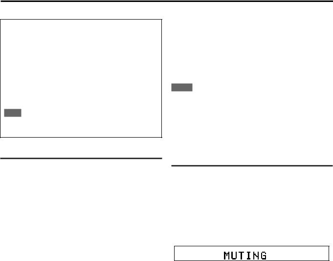
Turning off the sounds temporarily— Muting
From the remote control ONLY:
Press MUTING to turn off the sound through all connected speakers.
“MUTING” appears on the display and the volume turns off (the volume level indicator goes off).
ANALOG L |
|
R |
|
|
|
|
|
SUBWFR
To restore the sound, press MUTING again.
•Pressing VOLUME +/– (or turning MASTER VOLUME control on the front panel) also restores the sound.
13
Basic operations
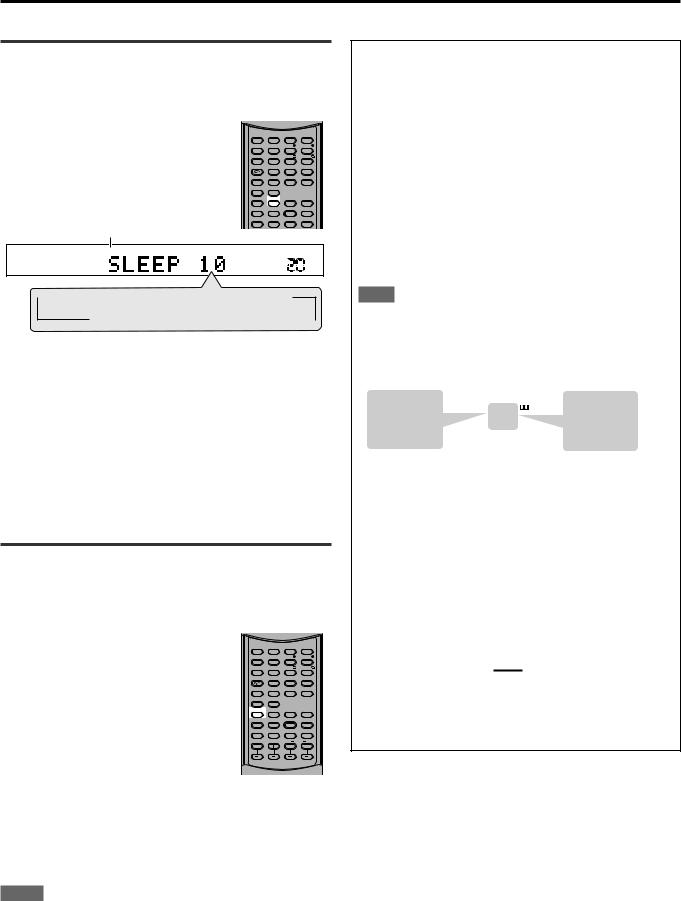
Turning off the power with the Sleep Timer
You can fall asleep while listening to music—Sleep Timer.
From the remote control ONLY:
Press SLEEP repeatedly.
The SLEEP indicator lights up on the display, and the shut-off time changes in 10 minutes intervals.
SLEEP indicator
AUDIO |
SUBTITLE TITLE/GROUP RETURN |
||
ZOOM |
|
BASS |
TREBLE |
|
1 |
2 |
3 |
|
|
BASS |
TREBLE |
VFP |
4 |
5 |
6 |
|
7 |
8 |
9 |
ANGLE |
TV RETURN |
|
100+ |
|
10 |
0 |
+10 |
REPEAT |
|
|
|
|
3D |
|
|
DIMMER |
SLEEP ANALOG/DIGITAL CANCEL |
||
|
|
INPUT |
|
SMART S. SETUP |
BASS BOOST |
|
.POSITION |
|
|
TONE |
|
|
|
|
SURROUND |
TEST |
EFFECT |
DECODE |
|
SUBWFR |
CENTER |
L |
SURR R |
ANALOG L |
|
R |
SLEEP |
|
|
|
|
|
|
SUBWFR
VOL |
 10
10  20
20  30
30  40
40  50
50  60
60
0 (Canceled) 90
90 80
80 70
70 
When the shut-off time comes:
The receiver turns off automatically.
To check or change the remaining time until the shut-off time:
Press SLEEP once.
The remaining time (in minutes) until the shut-off time appears.
• To change the shut-off time, press SLEEP repeatedly.
To cancel the Sleep Timer:
Press SLEEP repeatedly until “SLEEP 0” appears on the display. (The SLEEP indicator goes off.)
• Turning off the power also cancels the Sleep Timer.
Changing the display brightness
You can dim the display.
From the remote control ONLY:
Press DIMMER repeatedly.
•Each time you press the button, the indication changes as follow:
DIMMER 1: • Dims the display slightly.
• Dims the blue indication lighting source lamps.
DIMMER 2: • Dims the display more than
DIMMER 1.
•Dims the blue indication lighting source lamps (same as DIMMER 1).
DIMMER 3: Turns off the display and the blue indication lighting source lamps.
DIMMER OFF: Cancels the dim (normal display).
AUDIO |
SUBTITLE TITLE/GROUP RETURN |
||
ZOOM |
|
BASS |
TREBLE |
|
1 |
2 |
3 |
|
|
BASS |
TREBLE |
VFP |
4 |
5 |
6 |
|
7 |
8 |
9 |
ANGLE |
TV RETURN |
|
100+ |
|
10 |
0 |
|
REPEAT |
|
|
|
|
3D |
|
|
DIMMER |
SLEEP ANALOG/DIGITAL CANCEL |
||
|
|
INPUT |
|
SMART S. SETUP |
BASS BOOST |
|
.POSITION |
|
|
TONE |
|
|
|
|
SURROUND |
TEST |
EFFECT |
DECODE |
|
SUBWFR |
CENTER |
L |
SURR R |
NOTES
•When setting speakers and basic items or adjusting sound, select “DIMMER OFF” to confirm the setting you make on the display.
•When selecting DVD or DVD MULTI as a source using the remote control, DIMMER functions for the DVD player. To dim the display and indication on the receiver, select a source except DVD or DVD
MULTI on the remote control, and then press DIMMER.
Basic adjustment of auto memory
This receiver memorizes sound settings for each source:
•when you turn off the power,
•when you change the source, and
•when you change the analogue/digital input mode (see page 11).
When you change the source, the memorized settings for the newly selected source are automatically recalled.
The following can be stored for each source:
•Analogue/digital input mode (see page 11)
•Tone adjustment (see page 21)
•Balance (see page 21)
•Bass boost (see page 22)
•Input attenuator mode (see page 22)
•Subwoofer output level (see page 22)
•Subwoofer audio position (see page 22)
•Surround/DSP mode selection (see pages 28 – 33)
NOTE
If the source is FM or AM (MW), you can assign a different setting for each band.
Signal and speaker indicators on the display
Signal indicators |
|
|
|
|
|
|
Speaker indicators |
|||||||||||
L |
C |
R |
|
|
|
|
|
|
|
|
|
|
|
|
|
|
|
|
|
|
|
|
|
|
|
|
L C |
R |
|||||||||
|
|
LFE |
|
L |
|
C |
|
R |
|
|
|
|
|
|
|
|
|
|
|
|
|
|
|
SUBWFR |
|
|
|||||||||||
|
|
|
SUBWFR LFE |
|
|
|||||||||||||
LS |
S |
RS |
|
LS |
|
S |
|
RS |
|
|
|
|
|
|
|
|
|
|
|
|
|
|
|
|
|
|
|
|
|
|
|
|
|
|
|||
|
|
|
|
|
|
|
|
LS |
|
RS |
|
|||||||
The following signal indicators light up —:
L:• When digital input is selected: Lights up when the left channel signal comes in.
•When analogue input is selected: Always lights up.
R:• When digital input is selected: Lights up when the right channel signal comes in.
•When analogue input is selected: Always lights up.
C:Lights up when the center channel signal comes in.
LS: Lights up when the left surround channel signal comes in.
RS: Lights up when the right surround channel signal comes in.
S:Lights up when the monaural surround channel signal comes in.
LFE: Lights up when the LFE channel signal comes in.
The speaker indicators light up as follows:
•The subwoofer indicator (SUBWFR) lights up when “SUBWFR” is set to “USE” for Quick Setup (see page 16) or to “YES” for Manual Setup (see page 17).
•The other speaker indicators light up only when the corresponding speaker is set to “SML” or “LRG,” and also when required for the current playback.
14

RX-ES1SL
Speaker settings
To obtain the best possible surround effect from Surround/DSP modes (see pages 28 to 33), you need to set up the speaker and subwoofer information after all the connections are completed. You can set the speaker information using one of the following three methods.
Smart Surround Setup: Set the speakers information automatically by one simple action—clapping hands. The delay time and output level for the center and surround speakers are set automatically.
Quick Setup: Set the speakers and subwoofer information quickly by entering the use of the subwoofer, the number of the speakers, and your room size.
Manual Setup: Set the speakers and subwoofer information manually.
• Before starting the speaker setting, connect and position the speakers and subwoofer (see page 7) and turn on the receiver.
Setting the speakers information automatically—Smart Surround Setup
The distance from your listening point to the speakers is one of the important element to obtain the best possible sound effect for the Surround/DSP modes.
You need to set the delay time of the center and surround speakers relative to the front speakers so that sounds through all the speakers can reach you at the same time (see also page 18).
By using Smart Surround Setup, the speaker delay time and output level are automatically calculated by one simple action—clapping hands.
•To use Smart Surround Setup effectively, connect both the center and surround speakers.
•You can also set the crossover frequency, the low frequency effect attenuator and the dynamic range compression manually (see page 18).
•When you change your speakers, do the following steps again.
From the remote control ONLY:
AUDIO |
SUBTITLE TITLE/GROUP RETURN |
|
|
||
ZOOM |
|
BASS |
TREBLE |
|
|
|
1 |
2 |
3 |
|
|
|
|
BASS |
TREBLE |
|
|
VFP |
4 |
5 |
6 |
|
|
|
7 |
8 |
9 |
When operating the |
|
ANGLE |
TV RETURN |
|
100+ |
|
|
|
10 |
0 |
+10 |
receiver using the remote |
DVD |
REPEAT |
3D |
|
|
||
DIMMER |
SLEEP ANALOG/DIGITAL CANCEL |
control, always set the |
AUDIO/TV |
||
|
|
INPUT |
|
||
SMART S. SETUP BASS BOOST |
|
A.POSITION |
mode selector to AUDIO/ |
/VCR/STB |
|
|
|
TONE |
|
||
|
|
|
SURROUND |
|
|
TEST |
EFFECT |
DECODE |
|
TV/VCR/STB. |
|
SUBWFR CENTER |
L SURR R |
|
|||
Before you start, remember...
There is a time limit in doing the following steps. If the setting is canceled before you finish, start from step 2 again.
1 Take your position where you listen to the sound.
2 Press and hold SMART S. SETUP.
“SETTING UP” flashes on the display.
ANALOG L |
|
R |
|
|
|
|
|
SUBWFR
VOL |
3Confirm “SETTING UP” stops flashing and clap your hands over your head once while “SETTING UP” appears on the display.
The receiver starts detecting the level of the sound coming through all speakers (except the subwoofer).
After detecting the sound, one of the following indications appears on the display.
SUCCESSFUL: Sound of your clapping is successfully detected. The receiver sets the delay time and the output level of the center and surround speakers automatically.
SILENT: The receiver cannot detect sound from some speakers.
SILENT-ALL: The receiver cannot detect any sound from all speakers.
FAILED: The receiver cannot detect both right and left channels for the front and/or surround speakers correctly.
•When the receiver cannot detect the sound correctly (“SILENT,”
“SILENT-ALL” or “FAILED” appears on the display), “SETTING
UP” appears on the display again then repeat step 3.
•The speaker delay time and output levels are set automatically when:
—the receiver detects the sound as “SILENT” twice in succession.
—the receiver detects the sound as “SILENT” at the third time after detecting “SILENT”, “SILENT-ALL” and/or “FAILED” twice.
•When the receiver detects the sound as “SILENT-ALL” or “FAILED” three times, “MANUAL” appears on the display. Set the speaker and subwoofer information using Quick Setup (see page 16) or Manual Setup (see page 17), and the speakers' output levels for the center and surround speakers (see pages
31 to 33).
To cancel Smart Surround Setup, press SMART S. SETUP while
“SETTING UP” flashes on the display.
•Any other operations cannot be done after “SETTING UP” stops flashing. Complete the Smart Surround Setup.
NOTES
•You need to set the subwoofer information and output level manually (see pages 17 and 21).
•When you use Smart Surround Setup, the speaker delay time and output levels you have set before will be ineffective.
•Set the speakers information using Quick Setup (see page 16) or
Manual Setup (see page 17), and the speakers’ output levels for the center and surround speakers (see pages 31 to 33) when: —you like to change the speaker setting made by Smart Surround
Setup
—Smart Surround Setup is not done correctly due to some factors such as the environment, speaker types and clapping strength.
•Smart Surround Setup will not be done correctly if your body or other object blocks the sound.
•Do not clap your hands hard because it may hurt your hands.
15
Speaker settings
Setting the speakers and subwoofer information quickly—Quick Setup
Entering the use of the subwoofer, the number of the speakers, and your room size, the center and surround speakers’ delay time is automatically calculated.
•When you change your speakers, register the information about the speakers again.
•You can also set the crossover frequency, the low frequency effect attenuator and the dynamic range compression manually (see page 18).
5 Press SET.
“ENTER USE OF SUBWOOFER” scrolls on the display.
6Turn MULTI JOG to select whether or not you have connected a subwoofer.
• As you turn MULTI JOG, the indication changes as follow:
ANALOG L |
|
R |
|
|
|
|
|
SUBWFR
VOL |
|
|
|
|
|
|
|
|
|
|
|
SOURCE SELECTOR |
MASTER VOLUME |
|
TV DIRECT |
SETTING |
ADJUST |
SURROUND |
|
|
|
|
|
SET / TUNER PRESET |
MULTI JOG |
|
|
|
|
|
|
|
|
|
|
|
|
|
PHONES |
STANDBY / ON |
STANDBY |
|
|
|
DVD MULTI |
DVD |
STB |
VCB |
TV |
FM / AM |
|
|
* Initial setting |
USE * |
|
NO |
|
|||
|
|
|
7 Press SET.
“ENTER ROOM SIZE” scrolls on the display.
On the front panel ONLY:
Before you start, remember...
There is a time limit in doing the following steps. If the setting is canceled before you finish, start from step 1 again.
1 Press SETTING.
MULTI JOG now works for the setting operation.
2Turn MULTI JOG until “QUICK SETUP” appears on the display.
• As you turn MULTI JOG, the indication changes as follow:
ANALOG L |
|
R |
|
|
|
|
|
SUBWFR
VOL |
SUBWFR 
 FRNT SP
 CNTR SP
 SURR SP
 CNTR DL
 SURR DL

CROSS 
 LFE
LFE 
 D.COMP DIGITAL IN
 AUTO SR
 MODE
MODE
QUICK SETUP |
|
(Back to the beginning) |
|
3 Press SET.
“ENTER THE NUMBER OF SPEAKERS” scrolls on the display.
•Once you have selected “QUICK SETUP,” previously adjusted speaker setting is cleared.
4Turn MULTI JOG to select the number of the speakers you have connected.
• As you turn MULTI JOG, the indication changes as follow:
ANALOG L |
|
R |
|
|
|
|
|
SUBWFR
VOL |
5 SPEKAERS* 
 3 SPEAKERS

 4 SPEAKERS

5 SPEAKERS*: Select when the front, center and surround speakers are connected.
4 SPEAKERS: Select when the front and surround speakers are connected.
3 SPEAKERS: Select when the front and center speakers are connected.
* Initial setting
Each speaker size is registered appropriately according to the number of the connected speakers. For details, see the list
“Speaker size according to the number of speakers” on the right.
8Turn MULTI JOG to select the room size.
• As you turn MULTI JOG, the indication changes as follow:
ANALOG L |
|
R |
|
|
|
|
|
SUBWFR
VOL |
SMALL* 
 MEDIUM
LARGE
* Initial setting
The center and surround speakers’ delay time is registered appropriately according to the room size. For details, see the list
“Speaker delay time according to room size” below.
9 Press SET to finish the setting.
“SETUP END” appears for a while, then the indication of the previously selected source appears on the display.
NOTES
•The setting you have made is not registered until “SETUP END” appears on the display.
•Performing any operation other than volume and dimmer adjustment cancels Quick Setup process.
•When you want to change the speaker and subwoofer information after Quick Setup, use Manual Setup (see page 17).
Speaker size according to the number of speakers
Number of |
Subwoofer |
Front |
Center |
Surround |
speakers |
|
|
|
|
|
|
|
|
|
3 |
NO |
LRG (large) |
SML (small) |
NO |
|
|
|
|
|
3 |
USE (YES) |
SML (small) |
SML (small) |
NO |
|
|
|
|
|
4 |
NO |
LRG (large) |
NO |
SML (small) |
|
|
|
|
|
4 |
USE (YES) |
SML (small) |
NO |
SML (small) |
|
|
|
|
|
5 |
NO |
LRG (large) |
SML (small) |
SML (small) |
|
|
|
|
|
5 |
USE (YES) |
SML (small) |
SML (small) |
SML (small) |
Speaker delay time according to room size
When selecting “SMALL ROOM,” |
|
C |
R |
• Center speaker delay time |
L |
||
|
|
|
|
is set to 1 msec. |
|
|
2.4 m |
• Surround speakers delay time |
|
|
2.1 m |
is set to 3 msec. |
|
|
1.8 m |
|
|
1.5 m |
|
|
|
|
|
|
LS |
|
RS |
16
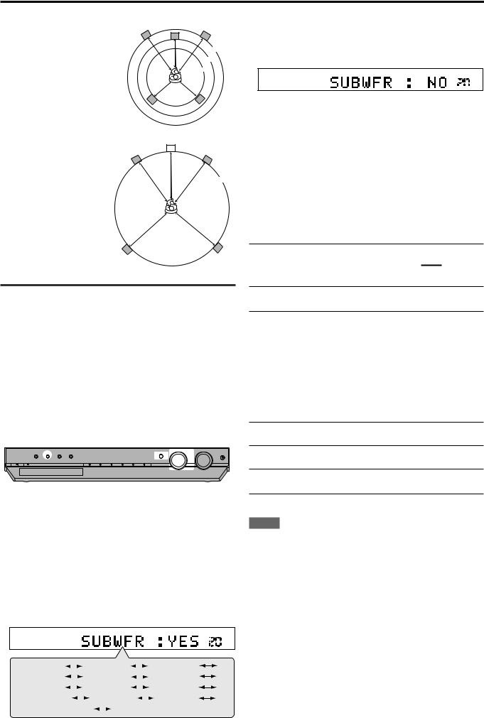
Speaker settings
When selecting “MEDIUM ROOM,” |
C |
R |
L |
||
• Center speaker delay time |
|
|
is set to1 msec. |
|
2.7 m |
• Surround speakers delay time |
|
2.4 m |
is set to 2 msec. |
|
2.1 m |
LS |
|
RS |
When selecting “LARGE ROOM,” |
|
C |
|
|
|
R |
|
• Center speaker delay time |
L |
|
|
is set to 0 msec. |
|
|
|
• Surround speakers delay time |
|
|
3.0 m |
is set to 0 msec.
LS |
RS |
Setting the speakers and subwoofer information manually—Manual Setup
You can set the following speakers and subwoofer information manually as you prefer. When you change your speakers, register the information again.
•Subwoofer information—SUBWFR
•Speaker size—FRNT SP, CNTR SP, SURR SP
•Speaker delay time—CNTR DL, SURR DL
•Crossover frequency—CROSS
•Low frequency effect attenuator—LFE
•Dynamic range compression—D.COMP
3Turn MULTI JOG to select the appropriate setting for the item selected in step 2, then press SET.
Your setting is stored.
ANALOG L |
|
R |
|
|
|
|
|
VOL


EX.: When selecting “NO” for “SUBWFR.”
4If you would like to set other items, repeat steps 2 and 3.
Setting the subwoofer information
— SUBWFR (subwoofer)
Register whether you have connected a subwoofer or not.
YES*: Select when you have connected a subwoofer. The subwoofer speaker indicator (SUBWFR) lights up on the display (see page 14). You can adjust the subwoofer output level (see page 22).
NO: Select when you have not connected or have disconnected a subwoofer.
* Initial setting
Setting the speakers size
—FRNT SP (front speakers), CNTR SP (center speaker), SURR SP (surround speakers)
Register the sizes of all the connected speakers.
Operating procedure
|
|
|
|
|
|
|
|
|
|
|
SOURCE SELECTOR |
MASTER VOLUME |
|
TV DIRECT |
SETTING |
ADJUST |
SURROUND |
|
|
|
|
|
SET / TUNER PRESET |
MULTI JOG |
|
|
|
|
|
|
|
|
|
|
|
|
|
PHONES |
STANDBY / ON |
STANDBY |
|
|
|
DVD MULTI |
DVD |
STB |
VCB |
TV |
FM / AM |
|
|
On the front panel ONLY:
Before you start, remember...
There is a time limit in doing the following steps. If the setting is canceled before you finish, start from step 1 again.
1 Press SETTING.
MULTI JOG now works for the setting operation.
2Turn MULTI JOG until the setting item you want to set appears on the display, then press SET.
• As you turn MULTI JOG, the indication changes as follow:
ANALOG L |
|
R |
|
|
|
|
|
SUBWFR
VOL |
SUBWFR |
|
|
|
|
|
|
FRNT SP |
|
|
|
|
|
|
|
CNTR SP |
|||
|
|
|
|
|
|
|
|
|
|
|||||||||
SURR SP |
|
|
|
|
CNTR DL |
|
|
|
|
|
|
SURR DL |
||||||
|
|
|
|
|
|
|
|
|
||||||||||
CROSS |
|
|
|
LFE |
|
|
|
|
|
D.COMP |
||||||||
|
|
|
|
|
|
|
||||||||||||
DIGITAL IN |
|
AUTO SR |
|
|
|
|
MODE |
|||||||||||
|
|
|
|
|
|
|
|
|||||||||||
QUICK SETUP |
|
|
(Back to the beginning) |
|||||||||||||||
|
|
|||||||||||||||||
LRG (large): Select when the cone speaker size is larger than 12 cm.
SML (small)*: Select when the cone speaker size is smaller than 12 cm.
NO: Select when you have not connected a speaker. (Not selectable for the front speakers.)
* Initial setting
NOTES
•If you have selected “SML (small)” for the front speaker size, you cannot select “LRG (large)” for the center and surround speaker sizes.
•If you have selected “NO” for the subwoofer setting (see above and page 16), you can only select “LRG (large)” for the front speaker size.
CONTINUED ON THE NEXT PAGE
17

Speaker settings
Setting the speaker delay time
—CNTR DL (center speaker delay), SURR DL (surround speakers delay)
You can set the speaker delay time easily by using Smart Surround Setup (see page 15) or Quick Setup (see page 16).
The distance from your listening point to the speakers is one of the important element to obtain the best possible surround sound for the
Surround modes.
You need to set the delay time of the center and surround speakers relative to the front speakers so that sounds through all the speakers can reach you at the same time.
•1 msec increase (or decrease) in delay time corresponds to (30 cm) increase (or decrease) in distance.
CNTR DL*: Set the delay time for the center speaker within a range of 0 msec to 5 msec (in 1 msec intervals).
SURR DL*: Set the delay time for the surround speakers within a range of 0 msec to 15 msec (in 1 msec intervals).
* “0ms” is the initial setting.
|
front |
|
speaker |
Center speaker |
|
Left |
|
|
|
|
|
Left
speakersurround
Right speakerfront
3.0 m
2.7 m
2.4 m
2.1 m
surround Rightspeaker
Example: In this case,
set “CNTR DL” to “1ms” and set “SURR DL” to “2ms.”
Setting the crossover frequency—CROSS
Small speakers cannot reproduce the bass sounds efficiently. If you use a small speaker in any position, this receiver automatically reallocates the bass sound elements assigned to the small speaker to the large speakers.
To use this function properly, set this crossover frequency level according to the size of the small speaker connected.
•If you have selected “LRG (large)” for all speakers (see page 17), this function will not take effect.
80HZ: Select when the cone speaker unit built in the speaker is about 12 cm.
100HZ: Select when the cone speaker unit built in the speaker is about 10 cm.
120HZ: Select when the cone speaker unit built in the speaker is about 8 cm.
150HZ*: Select when the cone speaker unit built in the speaker is about 6 cm.
200HZ: Select when the cone speaker unit built in the speaker is less than 5 cm.
* Initial setting
NOTE
Crossover frequency is not valid for the HEADPHONE mode.
Setting the low frequency effect attenuator —LFE
If the bass sound is distorted while playing back software encoded with Dolby Digital or DTS, set the LFE level to eliminate distortion.
• This function takes effect only when the LFE signals come in.
0dB*: Normally select this.
–10dB: Select when the bass sound is distorted.
* Initial setting
Setting the dynamic range compression —D.COMP
You can compress the dynamic range (difference between maximum sound and minimum sound) of the reproduced sound. This is useful when listening to surround sound at night.
•This function takes effect only when playing back a source encoded with Dolby Digital.
NOTE
If you have selected “NO” for the center and surround speakers setting (see page 17), you cannot set the speaker delay time for the center and surround speakers.
OFF: Select when you want to enjoy surround with its full dynamic range. (No effect applied.)
MID*: Select when you want to reduce the dynamic range a little.
MAX: Select when you want to apply the compression effect fully. (Useful at night.)
* Initial setting
18
 Loading...