

Jvc KD-X220-UT, KD-X220-UR, KD-X220-U, KD-X220-J, KD-X220-EY Service Manual
...
SERVICE MANUAL
MA606<Rev.002>20154SERVICE MANUAL
KD-X120EE, KD-X120EU, KD-X120U,
KD-X120UT, KD-X125EE, KD-X220E,
KD-X220EN, KD-X220EY, KD-X220J,
KD-X220U, KD-X220UR, KD-X220UT
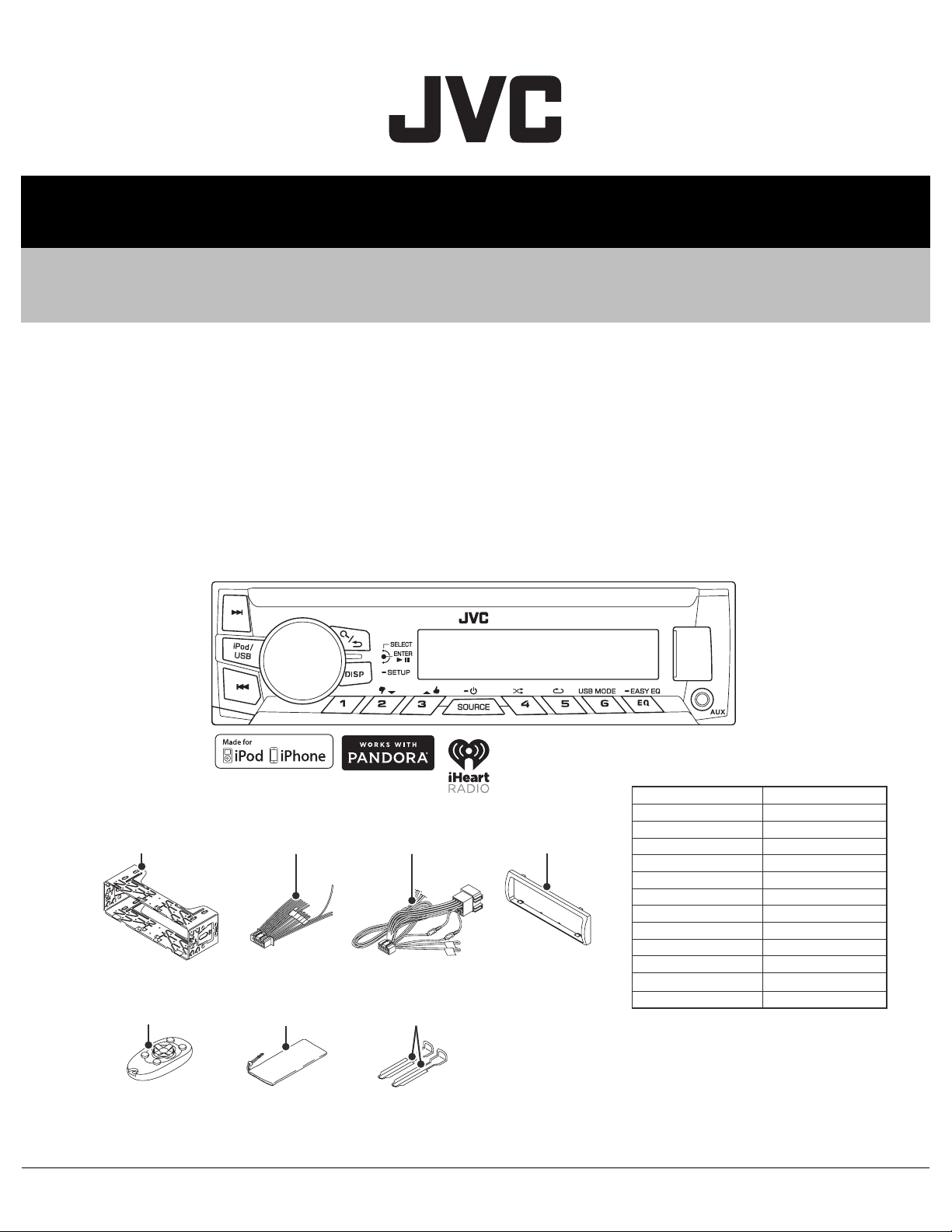
DIGITAL MEDIA RECEIVER
Mounting sleeve
(GE20342-001A)
Remote control unit
(RM-RK52M)
COPYRIGHT © 2015 JVC KENWOOD Corporation
DC cord
(QAM1329-001)
Carrying case
(GE40521-001A)
COPYRIGHT © 2015 JVC KENWOOD Corporation
DC cord
(QAM13xx-00x)
Hook
(GE40646-001A) x2
Lead free solder used in the board (material: Sn-Ag-Cu, melting point: 219 Centigrade)
Lead free solder used in the board (material: Sn-Cu, melting point: 230 Centigrade)
Trim Plate
(GE20363-001A)
DETACHABLE PANEL
Model Parts number
KD-X120EE
KD-X120EU
KD-X120U
KD-X120UT
KD-X125EE
KD-X220E
KD-X220EN
KD-X220EY
KD-X220J
KD-X220U
KD-X220UR
KD-X220UT
CP-X120EED
CP-X120EUD
CP-X120UD
CP-X120UD
CP-X125EED
CP-X220ED
CP-X220ED
CP-X220ED
CP-X220JD
CP-X220UD
CP-X220UD
No.MA606<Rev.002>
2015/4
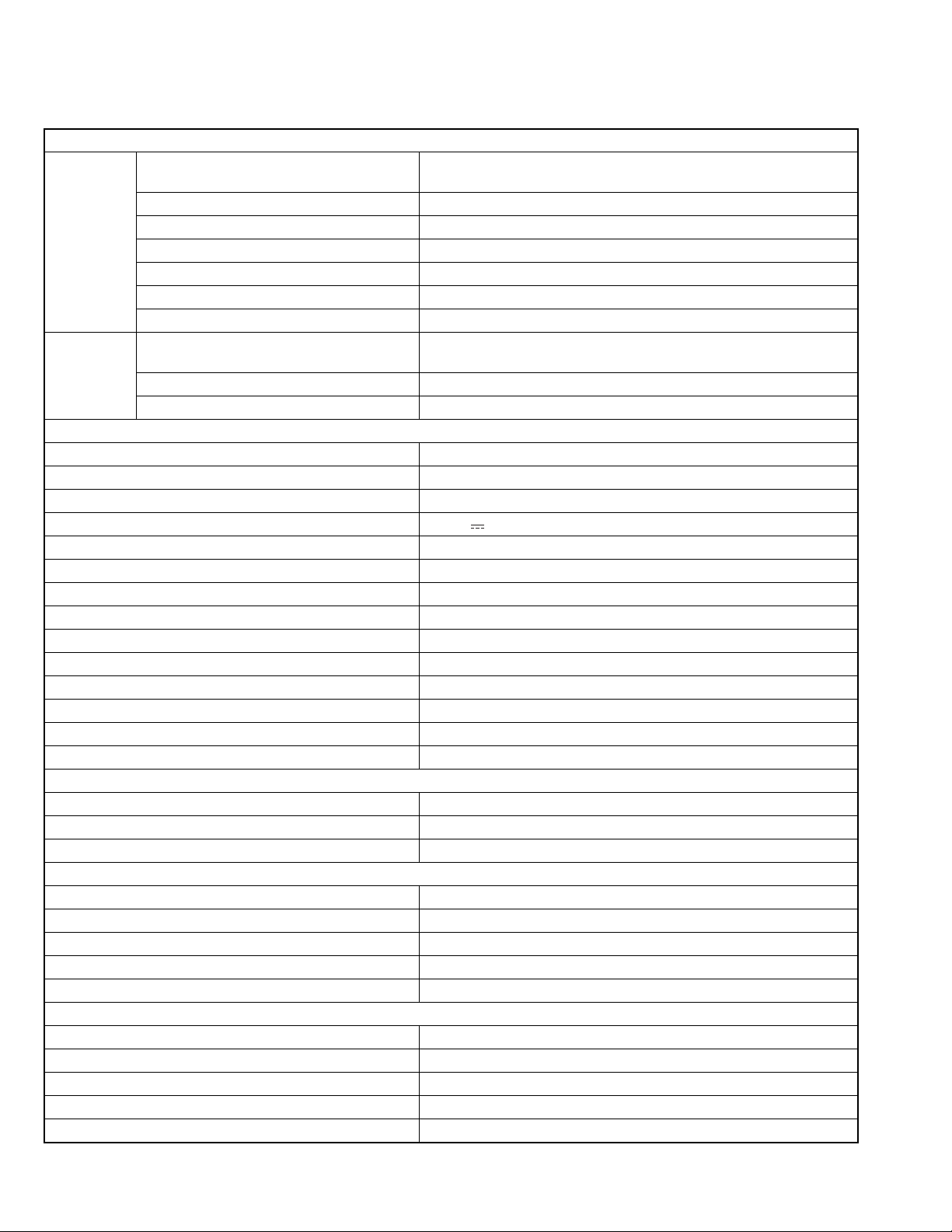
SPECIFICATION
For US
TUNER
FM Frequency Range 87.9 MHz - 107.9 MHz (200 kHz step)
87.5 MHz - 108.0 MHz (50 kHz step)
Channel Space Selection 50 kHz/200 kHz
Usable Sensitivity (S/N = 26 dB) 8.2 dBf (0.71 µV/75 Ω)
Quieting Sensitivity(DIN S/N = 46 dB) 17.2 dBf (2.0 µV/75 Ω)
Frequency Response (±3 dB) 30 Hz - 15 kHz
Signal-to-Noise Ratio (MONO) 64 dB
Stereo Separation (1 kHz) 40 dB
AM Frequency Range 530 kHz - 1 700 kHz (10 kHz step)
531 kHz - 1 611 kHz (9 kHz step)
Channel Space Selection 9 kHz/10 kHz
Usable Sensitivity (S/N = 20 dB) 29 dBµ (28.2 µV)
USB
USB Standard USB 1.1, USB 2.0 (Full speed)
Compatible Devices Mass storage class
File System FAT12/ 16/ 32
Maximum Supply Current DC 5 V 1 A
D/A Converter 24 Bit
Frequency Response (±1 dB) 20 Hz - 20 kHz
Signal-to-Noise Ratio (1 kHz) 105 dB
Dynamic Range 88 dB
Channel Separation 90 dB
MP3 Decode Compliant with MPEG-1/2 Audio Layer-3
WMA Decode Compliant with Windows Media Audio
AAC Decode AAC-LC ".m4a" files
WAV Decode RIFF waveform Audio Format (Linear PCM only)
FLAC Decode FLAC files
Auxiliary
Frequency Response (±3 dB) 20 Hz - 20 kHz
Input Maximum Voltage 1 000 mV
Input Impedance 30 kΩ
Audio
Maximum Output Power 50 W × 4 or 50 W × 2 + 50 W × 1 (Subwoofer = 4 Ω)
Full Bandwidth Power(at less than 1 % THD) 22 W × 4
Speaker Impedance 4 Ω - 8 Ω
Preout Level/Load (USB) 2 500 mV/10 kΩ
Preout Impedance ≤ 600 Ω
General
Operating Voltage (10.5 V - 16 V allowable) 14.4 V
Maximum Current Consumption 10A
Operating Temperature Range 0°C to + 40°C
Installation Size (W × H × D) 182 mm × 53 mm × 108 mm (7-3/16" × 2-1/8" × 4-5/16")
Weight 0.58 kg (1.3 lbs)
• Subject to change without notice.
(No.MA606<Rev.002>)2/20
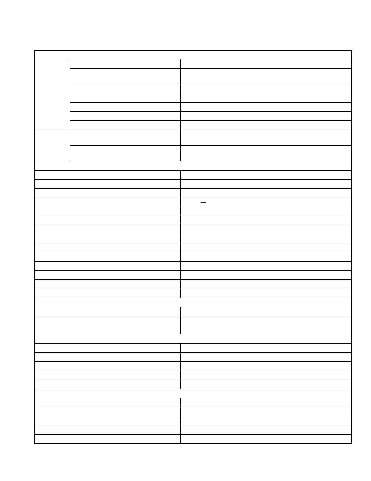
SPECIFICATION
For Europe
TUNER
FM Frequency Range (KD-X220) FM: 87.5 MHz - 108.0 MHz (50 kHz step)
Frequency Range (KD-X125/KD/X120) FM: 87.5 MHz - 108.0 MHz (50 kHz step)
FM-LO: 65.0 MHz - 74.0 MHz (30 kHz step)
Usable Sensitivity (S/N = 26 dB) 0.71 µV/75 Ω
Quieting Sensitivity(DIN S/N = 46 dB) 2.0 µV/75 Ω
Frequency Response (±3 dB) 30 Hz - 15 kHz
Signal-to-Noise Ratio (MONO) 64 dB
Stereo Separation (1 kHz) 40 dB
AM Frequency Range MW 531 kHz - 1 611 kHz (9 kHz step)
LW 153 kHz - 279 kHz (9 kHz step)
Usable Sensitivity (S/N = 20 dB) MW:28.2 µV
SW:50 µV
USB
USB Standard USB 1.1, USB 2.0 (Full speed)
Compatible Devices Mass storage class
File System FAT12/ 16/ 32
Maximum Supply Current DC 5 V 1 A
D/A Converter 24 Bit
Frequency Response (±1 dB) 20 Hz - 20 kHz
Signal-to-Noise Ratio (1 kHz) 105 dB
Dynamic Range 88 dB
Channel Separation 90 dB
MP3 Decode Compliant with MPEG-1/2 Audio Layer-3
WMA Decode Compliant with Windows Media Audio
AAC Decode AAC-LC ".m4a" files
WAV Decode RIFF waveform Audio Format (Linear PCM only)
FLAC Decode FLAC files
Auxiliary
Frequency Response (±3 dB) 20 Hz - 20 kHz
Input Maximum Voltage 1 000 mV
Input Impedance 30 kΩ
Audio
Maximum Output Power 50 W × 4 or 50 W × 2 + 50 W × 1 (Subwoofer = 4 Ω)
Full Bandwidth Power(at less than 1 % THD) 22 W × 4
Speaker Impedance 4 Ω - 8 Ω
Preout Level/Load (USB) 2 500 mV/10 kΩ
Preout Impedance ≤ 600 Ω
General
Operating Voltage (10.5 V - 16 V allowable) 14.4 V
Maximum Current Consumption 10A
Operating Temperature Range 0°C to + 40°C
Installation Size (W × H × D) 182 mm × 53 mm × 108 mm
Weight 0.58 kg
• Subject to change without notice.
(No.MA606<Rev.002>)3/20
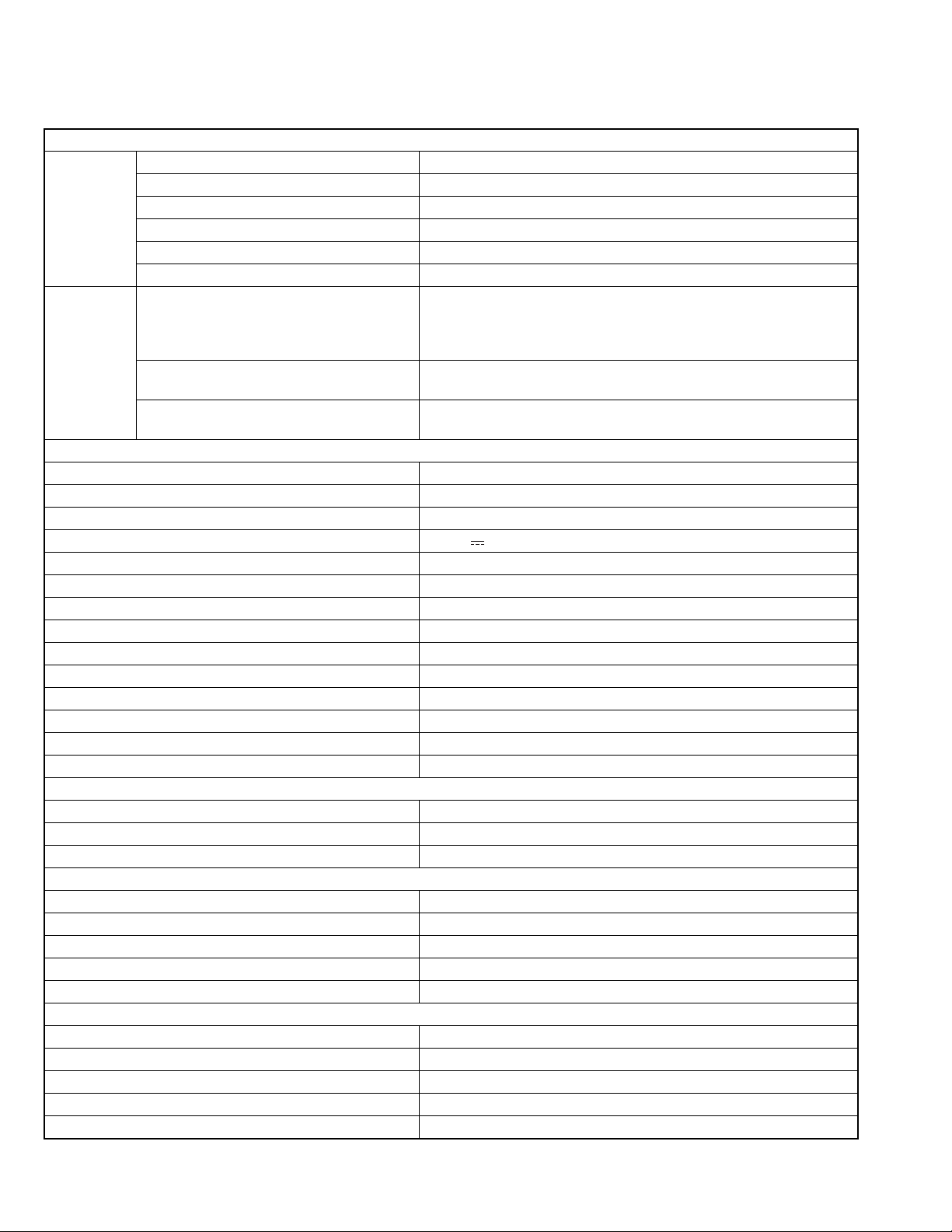
SPECIFICATION
For ASIA
TUNER
FM Frequency Range 87.5 MHz - 108.0 MHz (50 kHz step)
Usable Sensitivity (S/N = 26 dB) 8.2 dBf (0.71 µV/75 Ω)
Quieting Sensitivity(DIN S/N = 46 dB) 17.2 dBf (2.0 µV/75 Ω)
Frequency Response (±3 dB) 30 Hz - 15 kHz
Signal-to-Noise Ratio (MONO) 64 dB
Stereo Separation (1 kHz) 40 dB
AM Frequency Range Band 1 (MW): 531 kHz - 1 611 kHz (9 kHz step)
Band 2 (SW1): 2 940 kHz - 7 735 kHz (5 kHz step)
Band 3 (SW2): 9 500 kHz - 10 135 kHz /11 580 kHz - 18 135 kHz (5 kHz
step)
Channel Space Selection Band 1: 9 kHz
Band 2/3: 5 kHz
Usable Sensitivity (S/N = 20 dB) MW: 29 dBµ (28.2 µV)
SW: 30 dBµ (32 µV)
USB
USB Standard USB 1.1, USB 2.0 (Full speed)
Compatible Devices Mass storage class
File System FAT12/ 16/ 32
Maximum Supply Current DC 5 V 1 A
D/A Converter 24 Bit
Frequency Response (±1 dB) 20 Hz - 20 kHz
Signal-to-Noise Ratio (1 kHz) 105 dB
Dynamic Range 88 dB
Channel Separation 90 dB
MP3 Decode Compliant with MPEG-1/2 Audio Layer-3
WMA Decode Compliant with Windows Media Audio
AAC Decode AAC-LC ".m4a" files
WAV Decode RIFF waveform Audio Format (Linear PCM only)
FLAC Decode FLAC files
Auxiliary
Frequency Response (±3 dB) 20 Hz - 20 kHz
Input Maximum Voltage 1 000 mV
Input Impedance 30 kΩ
Audio
Maximum Output Power 50 W × 4 or 50 W × 2 + 50 W × 1 (Subwoofer = 4 Ω)
Full Bandwidth Power(at less than 1 % THD) 22 W × 4
Speaker Impedance 4 Ω - 8 Ω
Preout Level/Load (USB) 2 500 mV/10 kΩ
Preout Impedance ≤ 600 Ω
General
Operating Voltage (10.5 V - 16 V allowable) 14.4 V
Maximum Current Consumption 10A
Operating Temperature Range 0°C to + 40°C
Installation Size (W × H × D) 182 mm × 53 mm × 108 mm
Weight 0.58 kg
• Subject to change without notice.
(No.MA606<Rev.002>)4/20
SECTION 1
PRECAUTION
1.1 Safety Precautions
(1) This design of this product contains special hardware and
many circuits and components specially for safety purposes. For continued protection, no changes should be made
to the original design unless authorized in writing by the
manufacturer. Replacement parts must be identical to
those used in the original circuits. Services should be performed by qualified personnel only.
(2) Alterations of the design or circuitry of the product should
not be made. Any design alterations of the product should
not be made. Any design alterations or additions will void
the manufacturers warranty and will further relieve the
manufacture of responsibility for personal injury or property
damage resulting therefrom.
(3) Many electrical and mechanical parts in the products have
special safety-related characteristics. These characteristics are often not evident from visual inspection nor can the
protection afforded by them necessarily be obtained by using replacement components rated for higher voltage, wattage, etc. Replacement parts which have these special
safety characteristics are identified in the Parts List of Service Manual. Electrical components having such features
are identified by shading on the schematics and by ( ) on
the Parts List in the Service Manual. The use of a substitute
replacement which does not have the same safety characteristics as the recommended replacement parts shown in
the Parts List of Service Manual may create shock, fire, or
other hazards.
(4) The leads in the products are routed and dressed with ties,
clamps, tubings, barriers and the like to be separated from
live parts, high temperature parts, moving parts and/or
sharp edges for the prevention of electric shock and fire
hazard. When service is required, the original lead routing
and dress should be observed, and it should be confirmed
that they have been returned to normal, after reassembling.
1.2 Warning
(1) This equipment has been designed and manufactured to
meet international safety standards.
(2) It is the legal responsibility of the repairer to ensure that
these safety standards are maintained.
(3) Repairs must be made in accordance with the relevant
safety standards.
(4) It is essential that safety critical components are replaced
by approved parts.
(5) If mains voltage selector is provided, check setting for local
voltage.
1.4 Critical parts for safety
In regard with component parts appearing on the silk-screen
printed side (parts side) of the PWB diagrams, the parts that are
printed over with black such as the resistor ( ), diode ( )
and ICP ( ) or identified by the " " mark nearby are critical
for safety. When replacing them, be sure to use the parts of the
same type and rating as specified by the manufacturer.
(This regulation dose not Except the J and C version)
1.5 Remote control
The Lithium battery is in danger of explosion if replaced incorrectly. Replace it only with the same or equivalent type.
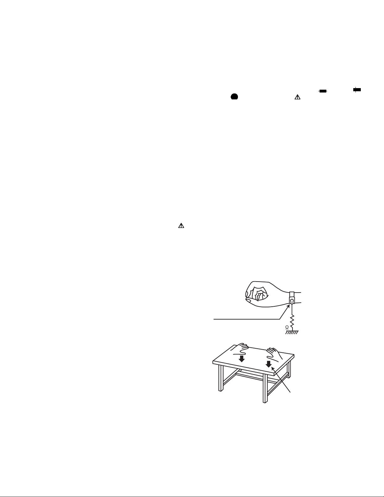
1.6 Preventing static electricity
Electrostatic discharge (ESD), which occurs when static electricity stored in the body, fabric, etc. is discharged, can destroy the
semi conductors. Take care to prevent this when performing repairs.
1.6.1 Grounding to prevent damage by static electricity
Static electricity in the work area can destroy the semi conductors.
Be careful to use proper grounding in the area where repairs are
being performed.
(1) Ground the workbench
Ground the workbench by laying conductive material (such
as a conductive sheet) or an iron plate over it before placing the unit on it.
(2) Ground yourself
Use an anti-static wrist strap to release any static electricity
built up in your body.
(caption)
Anti-static wrist strap
1M
Conductive material
(conductive sheet) or iron plate
1.3 Caution
Burrs formed during molding may be left over on some parts
of the chassis.
Therefore, pay attention to such burrs in the case of preforming repair of this system.
(No.MA606<Rev.002>)5/20
SECTION 2
SPECIFIC SERVICE INSTRUCTIONS
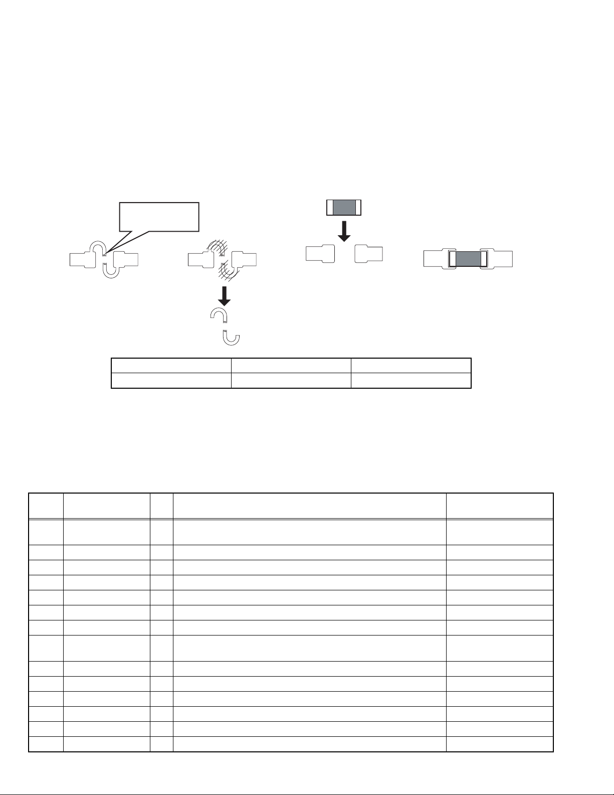
2.1 How to repair a fuse pattern
2.1.1 Purpose of fuse pattern
In order to prevent serious damage on the circuit, fuse pattern is prepared on the GND line of RCA Terminal. This damage may
take due to improper part replacement with a external equipment via RCA line.
2.1.2 Repair Procedure
(1) Check the shorted circuit at the meltdown point.
Need to clean up if the shorted circuit or carbonization happen at the fuse pattern.
(2) Add following part on the fuse pattern.
(3) Check output level.
Meltdown point
Part Number Part Name SPEC
F53-0513-08 PATTERN FUSE 4A
2.1.3 After finished repair
Due to improper part replacement, this meltdown occurs.
Thus please notice following information when the unit is returned to your customer.
Things to be checked before installing the unit.
(1) Check the GND line of external amplifier or other equipment which must connect properly.
(2) Check whether the GND line is not short-circuited with the battery terminal. (do not short-circuit these lines)
2.2 MICROCOMPUTER’S TERMINAL DESCRIPTION
IC701 (R5S726A0D216FP) on MAIN PWB ASSY
Pin No. Pin Name I/O Application
1 LCD_INH O Display On/Off Control L: Display OFF/
2 DAB_COM_ON O Enable DAB micon (For DAB model) H: ON/L: OFF
2 NC O No Use (for non DAB model)
3 PVcc - Power supply for I/O circuits
4 DZF I Zero Input Detect L: Mute OFF/H: Mute ON
5Vss -GND
6 PANEL_PON O Supply Control to Panel L: ON/H: OFF
7 DC_ERR2 I Detect DC Clip (for ST Power Amp IC) L: DC Error ON/
8 PWIC_MUTE O Muting Output for Power Amp IC L: Mute ON/H: Mute OFF
9 LCD_CE O LCD Driver IC Chip Enable Output (for LCD Model)
10 Vss - GND
11 LCD_CLK O LCD CLK Output
12 Vcc - Power supply
13 RGB_CLK O I2C Clock Output for RGB Driver (For RGB Model)
Processing/Operation/
Description
H: Display ON
H: DC Error OFF
(No.MA606<Rev.002>)6/20
Pin No. Pin Name I/O Application
13 PCB_TEST_MODE
_RX
14 LCD_DATA_SYS O LCD DATA Output (for LCD Model)
14 LCD/
RGB_DATA_SYS
14 PCB_TEST_MODE
_TX
15 USB_PON O Enable Output for High Side Switch L: HisideSW OFF/
16 PVcc - Power supply for I/O circuits
17 BT_DATA_BT I BT Data Input (For BT model only)
17 NC O No Use (for non BT model)
18 Vss - GND
19 BT_DATA_SYS O BT Data Output (For BT model only)
19 NC O No Use (for non BT model)
20 Vcc - Power supply
21 PWIC_STBY O Output to Power On Power Amp IC L: Standby/H: Play
22 SXM_DATA_SXM I SXM Data Input (For SXM model only)
22 NC O No Use (for non SXM model)
23 SXM_DATA_SYS O SXM Data Output (For SXM model only)
23 NC O No Use (for non SXM model)
24 DEBUG_1A O For Debug
24 DAB_COM_CLK O Clock to DAB (for DAB model only)
24 HD_SPICLK O Clock to HD Decoder (for HD model only)
25 DEBUG_1B O For Debug
25 DAB_REQ_SYS O Command Request from main micon to DAB micon (for DAB model)
25 HD_REQ_SYS O Command Request from SYS-com to HD (for HD model)
26 DEBUG_1C O For Debug
26 DAB_DATA__SYS O DAB Data Output (for DAB model only)
26 HD_DATA_SYS O HD Data Output (for DAB model only)
27 DAB_DATA_DAB I DAB Data Input (for DAB model only)
27 HD_DATA_HD I HD Data Input (for HD model only)
27 NC O No Use (for non DAB / HD model)
28 PVcc - Power supply for I/O circuits
29 FREQ_SEL O Frequency Select Pulse: Power On/
30 Vss - GND
31 ENC2 I Volume Encoder Pulse Input 2
32 ENC1 I Volume Encoder Pulse Input 1
33 REMO I Remocon Input L (Pulse): Remote control
34 LCD_DATA_LCD I LCD DATA Intput (for LCD Model)
35 MRC_DATA_MRC I Marine REMO Data Input UART 57.6kHz (For MARINE model)
35 DEBUG_2A O For Debug
36 PVcc - Power supply for I/O circuits
37 NC O System Clock Output to External Devices (for LCD Model)
I PCB Test Mode RX
O LCD and RGB DATA Output (for RGB Model)
O PCB Test Mode TX
No Use
Processing/Operation/
Description
H: HisideSW ON
L: Power Off
data/H: Standby
(No.MA606<Rev.002>)7/20
Pin No. Pin Name I/O Application
38 Vss - GND
39 RESET I Reset Input
40 Vss - GND
41 PLLVcc - Power supply for PLL
42 PAN_DET I Panel Detection input L: Panel Attached/
43 Vcc - Power supply
44 EXTAL I High Speed Clock 12MHz
45 XTAL O High Speed Clock 12MHz
46 Vss - GND
47 Vss - GND
48 PVcc - Power supply for I/O circuits
49 D-0 I/O USB Data- 0
50 D+0 I/O USB Data+ 0
51 ASEMD I ASE Mode Select Pin
52 NC I No Use
53 BT_MUTE I BT Mute L: Mute OFF/H: Mute ON
53 NC I No Use (for non BT model)
54 STAGE2 I Model Selecting Input 2
54 STEERING_REMO2I OE Remote In 2 (for DOP models)
Processing/Operation/
Description
H: Panel Detached
55 STAGE1 I Model Selecting Input 1
55 STEERING_REMO1I OE Remote In 1 (for DOP models)
56 TEL_MUTE I Tel Mute Detection Input (for JVC Model)
56 LINE_MUTE I Line Mute Detection Input (For KWD Model)
56 No Use I No Use (for non support Tel mute model)
57 DC_ERR1 I Detect DC Offset Error from EVOL IC L: DC Error ON/
H: DC Error OFF
58 Avss - GND
59 Avcc - Power Supply
60 Avref - Reference Power Supply
61 TRST I Debugging Interface. Reset Input.
62 ASEBRKAK/ASE-
BRK
63 TDO O Debugging Interface. Serial Output for Instructions and Data
64 TDI I Debugging Interface. Serial Input for Instructions and Data
65 TMS I Debugging Interface. Test Mode Select Signal Input.
66 TCK I Debugging Interface. Test Clock Input.
67 AUDIO_X2 O Audio Clock 16.9MHz (for External DAC)
68 AUDIO_X1 I Audio Clock 16.9MHz (for External DAC)
69 PVcc - Power supply for I/O circuits
70 SPBCLK O FLASH SPI Multi I/O Bus Clock output
71 Vss - GND
72 SPBSSL O FLASH SPI Multi I/O Bus Slave Select Output
73 SPBIO0 I/O FLASH SPI Multi I/O Bus I/O Data 0
74 SPBIO1 I/O FLASH SPI Multi I/O Bus I/O Data 1
I/O Emulator Break Mode Acknoledge/Break Input
(No.MA606<Rev.002>)8/20
Pin No. Pin Name I/O Application
75 SPBIO2 I/O FLASH SPI Multi I/O Bus I/O Data 2
76 Vss - GND
77 SPBIO3 I/O FLASH SPI Multi I/O Bus I/O Data 3
78 Vcc - Power supply
79 MD_CLK I Clock Mode Set (Power ON Reset)
EXTAL Pin Input Clock Ranges from 10 to 12 MHz
80 MD_BOOT I BOOT Mode Set L: Boot mode 0/
81 AUDIO_XOUT O DAC Audio Clock Output 16.9MHz
82 PVcc - Power supply for I/O circuits
83 DAB_PON O Control 3..3V power for DAB Module (for DAB model only) H: ON/L: OFF
83 HD_PON O Control 3.3V power for HD module (for HD model only) HD source= H: ON/
83 NC O No Use (for non DAB/non HD model)
84 Vss - GND
85 MUTE O Muting Output for Evol & Line Out L: Mute ON/H: Mute OFF
86 Vcc - Power supply
87 BT_RST O BT Reset Output (For BT model) L: Reset ON/
87 NC O No Use (for non BT model)
88 DCDC6V_PON O Enable Output for DC-DC Regulator
89 SXM_PWR O Power Supply for SXM (For SXM model only) L: PWR Off/H: PWR On
89 NC O No Use (for non SXM model)
90 DAB_REQ_DAB I Command Request from DAB micon to main micon
90 NC O No Use (for non DAB model)
91 EVOL_SCL I/O I2C Clock 391kHz for E-Vol
91 EP_SCL I/O I2C Clock 391kHz for E2PROM
91 TU_SCL I/O I2C Clock 391kHz for Tuner
92 EVOL_SDA I/O I2C Data for E-Vol
92 EP_SDA I/O I2C Data for E2PROM
92 TU_SDA I/O I2C Data for Tuner
93 IPOD_SCL O iPod Authentication IC I2C Clock Clock speed 23kHz
93 NC O No Use (For non-iPod Model)
94 IPOD_SDA O iPod Authentication IC I2C Data
94 NC O No Use (For non-iPod Model)
95 REG_SCL O I2C Clock for Regulator IC
96 REG_SDA O I2C Data for Regulator IC
97 NC O No Use
98 DIM_IN I Dimmer Control Input (for JVC Model) L: Dimmer Detect ON/
98 NC O No Use (For KWD Model) keep L output setting
99 REG_FLG I Power Detection L: Detect OFF/
100 Vss - GND
101 PVcc - Power supply for I/O circuits
102 MRC_REQ_MRC I Command Request from Marine REMO to SYS-com
(For MARINE model)
Processing/Operation/
Description
H: Boot mode 1
Other source= L: OFF
H: Reset OFF
H: Dimmer Detect OFF
H: Detect ON
(No.MA606<Rev.002>)9/20
Pin No. Pin Name I/O Application
102 NC O No Use (for non Marine model)
103 SSISCK O DAC Audio Serial Data Clock 44.1kHz
104 SSIWS1 O DAC L/R Clock 44.1kHz
105 MRC_PON O Enable Marine REMO Power Supply (For MARINE model)
105 DEBUG 2C O For Debug H: Power On / L: Power Off
106 SSITx O Servo DSP Data Output
107 Vss - GND
108 DAC_CCLK O DAC Control Data Clock
109 Vcc - Power supply
110 DAC_CDTI O DAC control Data Input
111 TU_RST O HELIO/CAYMAN (HD) Reset L: Reset ON/
111 NC O No Use (For non DAB/HD model)
112 PVcc - Power supply for I/O circuits
113 MRC_DATA_SYS O Marine REMO Data Output UART 57.6kHz (For MARINE model)
113 NC O No Use (for non Marine model)
114 Vss - GND
115 DAC_CS O DAC Chip Select
116 BEEP O Output for Beep Tone Generator H (Pulse): BEEP/L: OFF
117 MRC_REQ_SYS O Command Request from SYS-com to Marine REMO
(For MARINE model)
117 NC O No Use (for non Marine model)
118 PCB_TEST_MODE I PCB Test Mode Switch L: Normal Mode/H: Check
118 WDT O Watch Dog Timer output L: Normal Mode /
119 MRC_EN O Marine REMO Data Select (For MARINE model)
119 DEBUG_2B O For Debug
119 Field Test 2 O RDS data log output (standby for field test)
120 Field Test 1 O RDS data log output (standby for field test)
120 FDAC_RST O DAC reset L: DAC reset/
Processing/Operation/
Description
H: Reset OFF
Mode (After Reset software need to check the
pin input. If detect high it
should enter Serial Number mode)
H: Reset by WDT
H: DAC reset off
(No.MA606<Rev.002>)10/20
SECTION 3
DISASSEMBLY
3.1 Main body
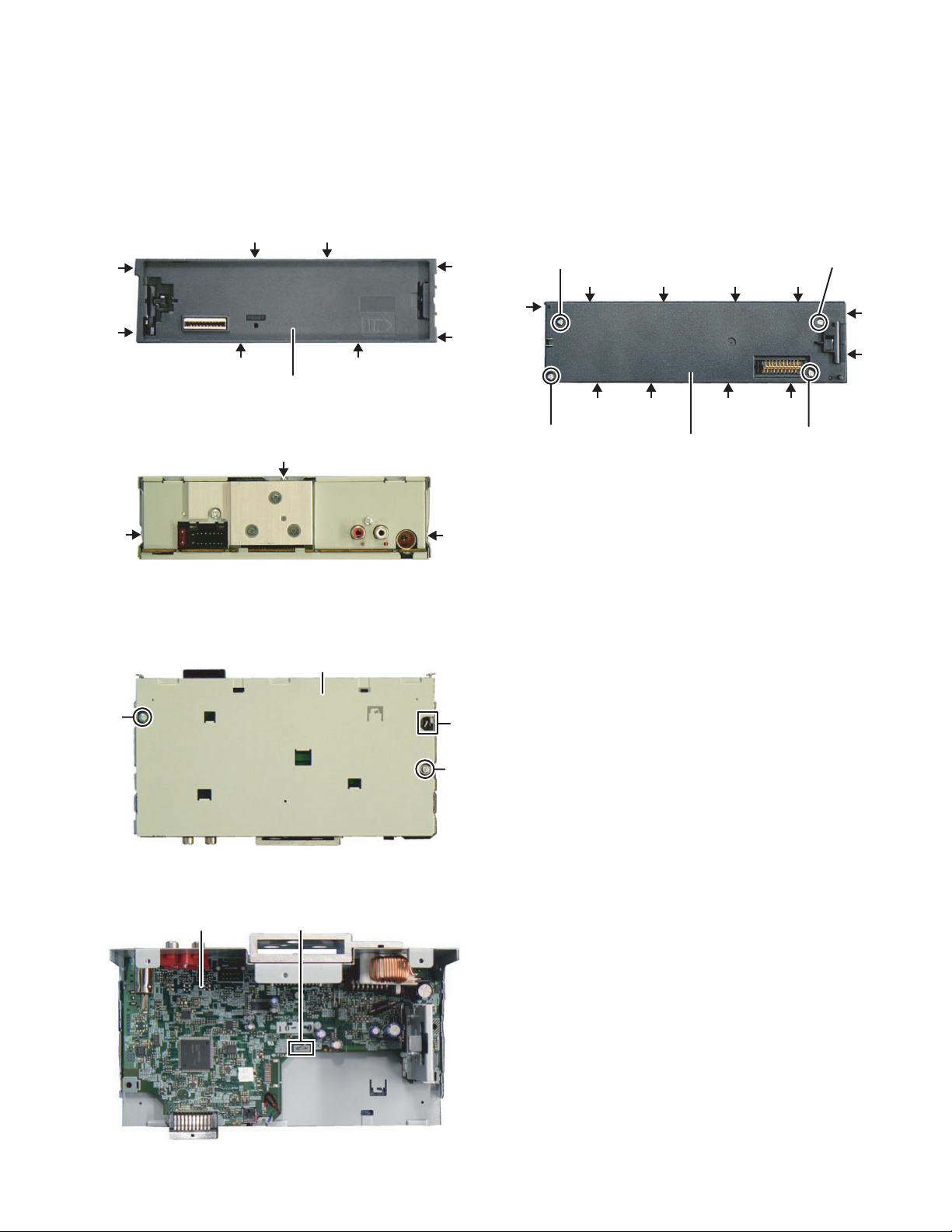
3.1.1 Removing the MAIN PWB (See Fig.1 to 4)
(1) Disengage the 8 hooks a, and remove the FRONT CHAS-
SIS ASSY.
(See Fig.
1)
aa
a
a
aa
FRONT CHASSIS ASSY
Fig.1
(2)
Remove the 3 screws A . (See Fig.
2)
A
A
Fig.2
(3) Remove the 2 screws B. (See Fig.3)
(4) Disengage the 1 hook b, and remove the BOTTOM
COVER with MAIN PWB.
(See Fig.3)
BOTTOM COVER
A
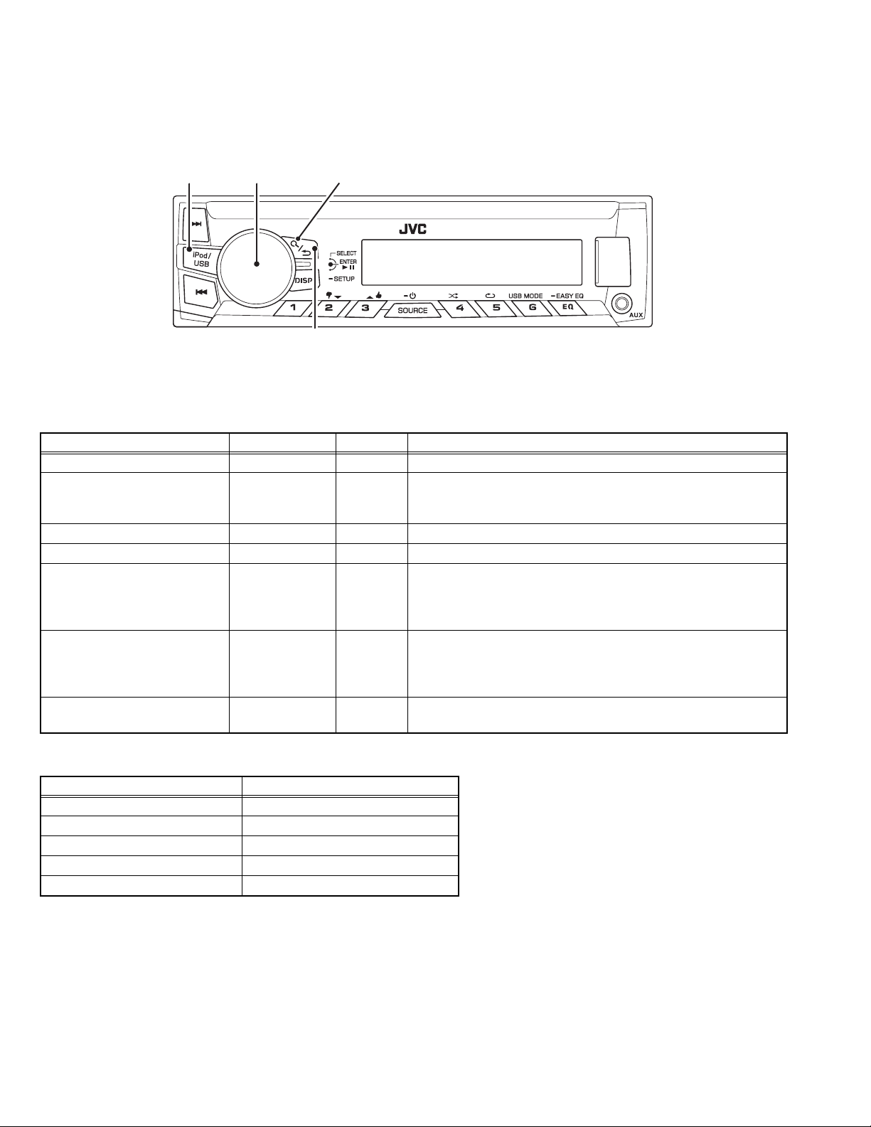
3.1.2 Removing the SWITCH PWB (See Fig.5)
(1) Remove the VOLUME KNOB.
(2) Remove the 4 screws D.
(3) Disengage the 11 hooks d, and remove the REAR
COVER.
(4) Remove the SWITCH PWB.
a
D
d d d d
d
D
d
a
d
d ddd
D
REAR COVER
Fig.5
D
B
Fig.3
(5) Disengage the 1 hook c, and remove the MAIN PWB.
(See Fig.4)
MAIN PWB
c
Fig.4
b
B
(No.MA606<Rev.002>)11/20
SECTION 4
ADJUSTMENT
4.1 Outline
4.1.1 Panel
ACCENT SEARCHVOL
RETURN
A symbol "" in the key column indicates that the key should be pressed and held for 1 second or longer.
4.1.2 Test Modes
These test modes are available in normal production ROM.
Transition to Test Mode shall be available during DC Error detection.
Test Mode Mode Source Operation
Production Test Mode - All Press and hold [DISP] key and [SOURCE] key and reset.
Service Test Mode Normal Mode /
Production Mode
Service Information Clear Mode - All Press and hold [RETURN] key and [SOURCE] key and reset.
DC Error Information Mode - All Press and hold [DISP] key and [] key and reset.
DOP Test Mode Normal Mode All Pressing and holding [SELECT] key, press [DISP] key for 7 sec-
Bluetooth Device Name Select
Mode
Tunisia Area /
Tuner Span Change Mode
4.1.3 Release from Test Mode
These actions will release the Test Mode and transit back to Normal Mode
Method Remarks
Reset All Modes
Momentarily voltage drop All Modes
ACC OFF All Modes
POWER OFF All Modes
Panel Detach All Modes
Normal Mode BT Audio Pressing and holding [ACCENT] key, press [DISP] key for 3 sec-
Normal Mode All Pressing and holding [VOL] key, press [RETURN] key for 3 sec-
All Pressing and holding [DISP] key, press [] key for 7 seconds.
(Starting to press [DISP] key and [] key at the same time can not
be entered into the mode)
onds.
(Starting to press [SELECT] key and [DISP] key at the same time
can not be entered into the mode)
onds.
(Starting to press [ACCENT] key and [DISP] key at the same time
can not be entered into the mode)
onds.
(No.MA606<Rev.002>)12/20
4.2 Production Test Mode
Press and hold [1] key and [3] key and reset.
4.2.1 Test Mode Defaults
During Production Test Mode, the following settings defer from the Normal Mode.
The settings will change immediately after mode activation.
Difference in action Setting value
Period to prohibit TEL/LINE MUTE function (Normal Mode: 10 secs) 1 second
Writing-in to E2PROM when DC error is detected Prohibited
"DEMO" item in Setup Menu OFF
Power supply during ACC OFF (Back Up On) MUTE terminal turns OFF after 2 seconds
"BEEP" item in Setup Menu ON
Volume range 0 to 44
Source change interval timer 0 seconds
When detected the 0 bit mute Mute off
Various setting item Setting value
Default Volume 15
"BASS BOOST" OFF
"LOUDNESS" OFF
"TEL MUTING" ON
Initial Source FM (Mechaless Models) /
CD (Non-Mechaless Models)
Language English
EQ FLAT
Fader / Balance Center
Digital Track Expander / Sound Reconstruction Set OFF
"VOL ADJUST" / "VOLUME OFFSET" 0
DEMO Mode Setting OFF
4.2.2 Mode structure
The following table shows the test modes that can be accessed from the different sources in Production Test Mode.
Source Test mode
Tuner TUNER Test Mode
USB USB Test Mode
4.2.3 Mode content
Syscon shall display the following information after entering Production Test Mode.
Display content Details
All lights on (BOTH LCD & LED including dual color switchable)
Set should not be able to power on if sub clock is not functioning.
The display is released when another operation is executed.
4.2.4 Special Operation by Key Input
Behaviour Details
Volume Adjustment to 44
Only during Normal display
(Invalid during Menu)
4.2.5 How to transit to Version Display Mode
Item Operation Display content Details
Transit to Display
Mode
RETURN
Pressing and holding [DISP] key, press [] key for 0.5 seconds.
(Starting to press [DISP] key and [] key at the same time can not be entered into
the mode)
Transit to Version Display Mode
(Default status: All Lights ON)
(No.MA606<Rev.002>)13/20
4.2.6 Version Display Mode
Item Operation Display content Details
All Lights ON/
All lights ON
TEST
Syscom version
display
Stage Setting ##: Stage Setting for current hardware
Y–SS##@@@
TSAGE :21 ##
## = File Number
@@@ = Syscon Version Number
Serial No. Display (8 digits)
Serial No. display
SN 00000000
Display to support ASCII characters
********: Blank
@@@@@@@@: EEPROM Read Error
DISP
(Toggle)
## = Blank: Verifying
OK: IC mounted
NG: IC not mounted
iPod IC Mount
Verification Status
Display
(USB models
only)
iPod ##
**: Non iPod support model
In addition, upon entering this mode, P-CON is
turned ON.
When a result is OK, P-CON is turned off.
Upon exit, P-CON remains OFF.
When a result is NG, P-CON is kept ON condition.
Upon exit, P-CON remains ON.
Pre-out Switch
(1 Pre-out / 2 Pre-
EQ
L/O SU B.W
Switch Pre-out with toggle
out model only)
Mode release
SOURCE
Transition
Mode release RETURN
Return to Normal mode
Return to Normal mode
4.2.7 Tuner Test Mode Specification
The following display shall be indicated according to the TUNER status.
Status Display content Details
TUNER IC
Communication Error
RDS/RBDS Specified
data reception
TUN CON NG
DRS STTE
Communication to TUNER IC not available
(indicated unless the mode is in Clock Display Mode).
Turn OFF P-CON forcibly if PS=RDS TEST is received.
P-CON recovers with Power OFF/ON.
Item Operation Display content Details
Display TUNER IC version
TUNER IC display EQ
TA2********
'AT2 ********' is eg "AtomIC2 57V1B101" indicating
"AtomIC2 TEF6657V1B 1.01"
*Not applicable and no function for HD and DAB models
(No.MA606<Rev.002>)14/20

4.2.8 USB Test Mode Specification
Applicable for iPod model only.
Status Display content Details
## = Blank: Verifying
NG: IC not mounted
**: Non iPod support model
Upon source change to USB source or USB
device plug in:
Verifying: Show "iPod: ##"
NG: Always show "iPod: NG" even during "NO
DEVICE" or playback.
**: Always show "iPod: **" even during "NO
iPod IC Mount Verification Status
Display
iPod ##
DEVICE"
OK: Change back to nomal display ("NO DE-
VICE / normal playback display).
In addition, upon enter to this mode, P-CON is
turned ON.
When a judgment result is OK, P-CON is
turned off.
Upon exit, P-CON still remain OFF.
When a judgment result is NG, P-CON is kept
ON condition.
Upon exit, P-CON still remain ON.
4.3 Service Test Mode
In the STANDBY source, while pressing and holding [2] key, press [6] key for 7 seconds.
(Starting to press [2] key and [6] key at the same time can not be entered into the mode)
4.3.1 Default status immediately after the mode activation
It shall be same as the normal activation.
4.3.2 Mode content
Syscon shall display the following information after entering this mode.
Display content Details
RSVT TES
Display is released when an operation is executed.
4.3.3 Common operation mode for only STANDBY sources
Item Operation Display content Details
Syscom version
display
6
Y–SS##@@@
## = File Number
@@@ = Syscon Version Number
00 to 50 are displayed in "XX".
Power ON
duration display
OPNTM HX0X
2
OPNTM XXXXX
For less than 1 hour, the display is indicated per 10
minutes.
00001 to 10922 are displayed in "XXXXX".
MAX 10922 (hours)
(No.MA606<Rev.002>)15/20
4.4 Service Information Clear Mode
Press and hold [2] key and [5] key and reset.
4.4.1 Default status immediately after the mode activation
It shall be same as normal activation.
4.4.2 Mode content
After entering this mode, Syscon shall clear the information stored for service and output the result to the display.
Cleared information changes will take place only after reset.
Display Display content Details
Data Clear in
IIINTALIZE
Data Clearing in Progress.
Progress
Data Clear OK Data cleared successfully.
Data Clear NG Data cleared with error, clear the data.
TDA A CLR OK
TDA A CLR NG
Display Blinks (250ms interval)
The following table shows the data that is cleared.
Information to Clear Details Storage area
Service information
DC error information
CD EJECT number of times display E2PROM
Forced Power OFF information display E2PROM
DC error 1 display (wrong connection & other detection information in detecting duration) E2PROM
DC error 2 display (capacitor leakage detection number information) E2PROM
Tuner Area Setting E2PROM
Tuner information
Preset Frequency E2PROM
Preset PI code E2PROM
Tagging information Token data memory index E2PROM
4.5 DC Error Information Mode
Press and hold [3] key and [6] key and reset.
4.5.1 Default status immediately after the mode activation
It shall be same as normal activation.
4.5.2 Mode content
Syscon shall display the following information after entering this mode.
Display content Details
DC ERR
DC OK
When DC error is detected
When DC error is not detected
Item Operation Display content Details
DC 1 ER R
DC ERR1display
DC1 OK
When wrong connection & DC error in other detection duration is detected.
When wrong connection & DC error in other detection duration is not detected.
Clear detection information when wrong connection
DC ERR1 clear
DC1 OK
& DC error in other detection duration is displayed.
(Clear data flash)
Display detecting number of times in capacitor leak-
DC ERR2 display
DC2 4
age detection duration.
#: 0 to 4
Clear number of times for detection information in
DC ERR2 clear
DC 2 0
capacitor leakage detection duration. (Clear data
flash)
(No.MA606<Rev.002>)16/20
4.6 DOP Test Mode
Pressing and holding [SELECT] key, press [DISP] key for 7 seconds.
4.6.1 DOP Mode Common Setting
Common settings for all car makers are as follows:
Demo: No demo animation
Remove all DEMO related items
Power on animation: Show carmaker's name
Only opening animation will show "Car maker's name"
Setup menu: Delete Demo
Color setting for RGB model: Refer to manufacturer preference below:
4.6.2 EEPROM DOP Read Error Display
In the case of an EEPROM read error or EEPROM DOP read error, the unit will behave accordingly.
(1) No Power on animation
(2) No Demo animation
(3) Demo removed in setup menu
(4) Color settings set to default
(5) Serial number display replaced by "SN @@@@@@@@"
4.6.3 Mode content
1) Enter DOP Mode. Pressing and holding [SELECT] key, press [DISP] key for 7 seconds.
Display content Details
PMODEDO
2) Select manufacturer setting.
Note: RGB color save as USER color. DEFAULT color set to USER.
The order is priority. Lower Priority brand need to press and hold(2 secs)
: press and hold (2 second) on button mentioned as follow
Display content Operation Display content Color
No Demo 1
Toyota 2
Honda 3
Ford 4
Suzuki 5
Hyundai 6
Mitsubishi
FIAT
Iveco DISP
Alfa Romeo 1
KIA 2
Volkswagen 3
Chevrolet 4
Peugeot 5
Nissan 6
Isuzu
Skoda
Daihatsu DISP
Default RETURN
JVC
TOYOTA
HONDA
FORD
SUZUKI
HYUNDA I
MI TSUBISHI
FIAT
IVECO
ALFA ROMEO
KIA
VOL KSWAGEN
CHE VRO L E T
PEUGEOT
NISSAN
ISUZU
SKODA
DAIHATSU
DEFAUL T
(same as Daihatsu)
Blue
Lime
Blue
Greenish Blue
Yellow Amber
Blue
Apple
White
White
Red
Blue
White
Red
Green
Orange
Red
Yellowish Green
Yellow Amber
(Same as Suzuki)
Return to default JVC normal setting.
7
25
5
3
16
7
14
User
User
13
7
User
13
24
16
13
User (R=22, G=31, B=0)
15
(No.MA606<Rev.002>)17/20
4.7 Tuner Span Change Mode
Pressing and holding [VOL] key, press [RETURN] key for 3 seconds.
4.7.1 Default status immediately after the mode activation
It shall be same as normal activation.
After selection of the setting item, the receiver should exit this mode and return to the display before entering this mode.
This setting will be stored in EEPROM.
4.7.2 Mode content
Syscon shall display the following information after entering this mode.
Item Operation Display content Details
Tuner Span
Change Mode
VOL +/-
(*1)
Tuner Span
Change Mode
VOL +/-
(*2)
Release Mode VOL
ARE A AS I A
AREA TUNISIA
AREA EUROPE
AREA TUNISIA
Default setting for Asia models.
Change to 'Asia' area type.
Change to 'Tunisia' area type.
Default setting for Europe models.
Change to 'Europe' area type.
Change to 'Tunisia' area type.
Depending on display pattern in normal mode.
*1: Only applicable for Asia ('U') models
*2: Only applicable for Europe ('E') models
(No.MA606<Rev.002>)18/20
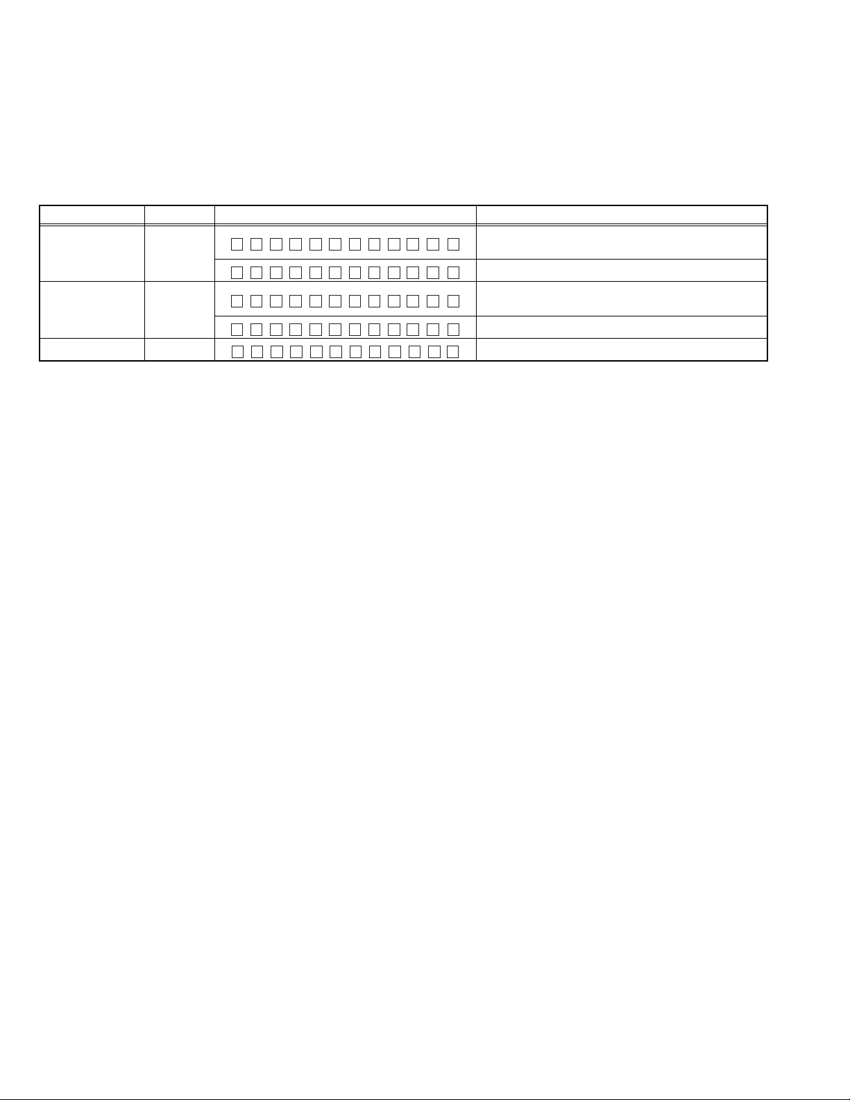
4.8 DC Offset error description
A
4.8.1 DC Offset detection circuit design
• Purpose:
To prevent breakdown, when occur DC offset between speaker output "+" and "-".
• Target:
Detect DC offset, then stop the Power Amp operation and shift
to specified condition.
4.8.2 Possible causes of DC offset at speaker output lines
(1) Mis-connection for Speaker output for example touch to car
body or battery line.
(2) Current leak of coupling capacitor for Power IC input.
(3) Current leak of AC-GND capacitor for Power IC AC-GND.
(4) Capacitor shorted of above parts due to foreign object.
C-tc
E-Vol
Win_TC
Win_In
DC Error
C-in
C-in
R3
C-in
C-in
C-ac2C-ac1
Sw5V
R2
R1
C3
R4
Audio Pwr Amp
In 1
In 2
In 3
In 4
AcGnd
Offset Detect
Out
Micon
ADC In
4.8.5 Manipulate after detect DC Offset
• If detected error 10 consecutive times, and 10th error occurred
in "Mis-connect detection period", judge as "Mis-connect".
• If detected error 10 consecutive times, and 10th error occurred
in "Capacitor leak detection period", judge as "Capacitor leak ".
• If detected error 10 consecutive times, and 10th error occurred
in "Other detection period" and detected another 10 errors consecutively, then judge as "Other".
• If judge as "Mis-connect".
- turn off speaker output.
- display "MISWIRING", check wiring connection then reset.
- key access disable except button of Eject, Reset and service
mode
- record error in EEPROM "DC1 ERR"
- the product is able to be recovered by Reset button.
• If judge as "Capacitor leak ".
- turn off speaker output.
- display "WIRING", check wiring connection then reset.
- key access disable except button of Eject, Reset and service
mode
- record error in EEPROM "DC2 #" (# means counter number)
- the product can be recovered by pressing the Reset button
before the capacitor leak error counter reach "DC2 4".
After that, only clear the counter back to "0" can recover the
product.
• If judge as "Other" (manipulation same as mis-connect)
SECTION 5
TROUBLESHOOTING
4.8.3 Type of checking
4.8.3.1 To detect DC Offset Error
• Mis-connection
- Short any one speaker out line to GND or Vcc
• Capacitor leak
- Parallel 330kΩ to either any one of coupling cap or AC-GND
capacitor (to simulate current leakage of capacitor)
- Shorted either any one of coupling capacitor or AC-GND capacitor.
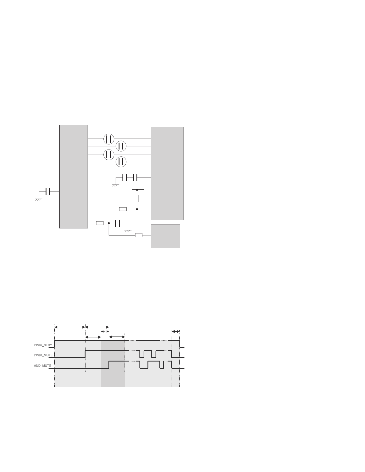
4.8.4 Detection Timing chart
PWIC_STBY
PWIC_MUTE
UD_MUTE
2.0sec or more
Missconnect
detection period
1.5sec or more
0.8sec
0.7sec or more
1.0sec
Capacitor leak
detection period
Other (miss detection etc.)
detection period
50ms
or more
5.1 How to cancel DC offset error
Check to be sure the terminals of the speaker leads are covered
with insulating tape properly, then reset the product.
If an error message does not disappear even after a reset, there
is a need for internal repair.
5.2 How to clear DC offset error recorded in EEPROM
Refer to “4.5 DC Error Information Mode”.
(No.MA606<Rev.002>)19/20
 Loading...