

Page 1

SERVICE MANUAL
CD RECEIVER
MA20420057
KD-G153
Area suffix
E ------------- Southern Europe
EX ------------ Northern Europe
EY ------------- Eastern Europe
EU ------------------------- Turkey
Lead free solder used in the board (material : Sn-Ag-Cu, melting point : 219 Centigrade)
TABLE OF CONTENTS
1 PRECAUTIONS . . . . . . . . . . . . . . . . . . . . . . . . . . . . . . . . . . . . . . . . . . . . . . . . . . . . . . . . . . . . . . . . . . . . . . . 1-3
2 SPECIFIC SERVICE INSTRUCTIONS . . . . . . . . . . . . . . . . . . . . . . . . . . . . . . . . . . . . . . . . . . . . . . . . . . . . . . 1-6
3 DISASSEMBLY . . . . . . . . . . . . . . . . . . . . . . . . . . . . . . . . . . . . . . . . . . . . . . . . . . . . . . . . . . . . . . . . . . . . . . . 1-7
4 ADJUSTMENT . . . . . . . . . . . . . . . . . . . . . . . . . . . . . . . . . . . . . . . . . . . . . . . . . . . . . . . . . . . . . . . . . . . . . . . 1-25
5 TROUBLESHOOTING . . . . . . . . . . . . . . . . . . . . . . . . . . . . . . . . . . . . . . . . . . . . . . . . . . . . . . . . . . . . . . . . . 1-26
COPYRIGHT © 2005 Victor Company of Japan, Limited
No.MA204
2005/7
Page 2

SPECIFICATION
AUDIO AMPLIFIER SECTION
Maximum Power Output Front 45 W per channel
Rear 45 W per channel
Continuous Power Output (RMS) Front 17 W per channel into 4 Ω, 40 Hz to 20 000 Hz at no more
than 0.8% total harmonic distortion.
Rear 17 W per channel into 4 Ω, 40 Hz to 20 000 Hz at no more
than 0.8% total harmonic distortion.
Load Impedance 4 Ω (4 Ω to 8 Ω allowance)
Tone Control Range Bass ±10 dB at 100 Hz
Treble ±10 dB at 10 kHz
Frequency Response 40 Hz to 20 000 Hz
Signal-to-Noise Ratio 70 dB
Line-Out Level/Impedance 2.0 V/20 kΩ load (full scale)
Output Impedance 1 kΩ
TUNER SECTION
Frequency Range FM 87.5 MHz to 108.0 MHz
AM (MW) 522 kHz to 1 620 kHz
(LW) 144 kHz to 279 kHz
FM Tuner Usable Sensitivity 11.3 dBf (1.0 µV/75 Ω)
50 dB Quieting Sensitivity 16.3 dBf (1.8 µV/75 Ω)
Alternate Channel Selectivity (400 kHz) 65 dB
Frequency Response 40 Hz to 15 000 Hz
Stereo Separation 30 dB
Capture Ratio 1.5 dB
MW Tuner Sensitivity 20 µV
Selectivity 35 dB
LW Tuner Sensitivity 50 µV
CD PLAYER SECTION
Type Compact disc player
Signal Detection System Non-contact optical pickup (semiconductor laser)
Number of channels 2 channels (stereo)
Frequency Response 5 Hz to 20 000 Hz
Dynamic Range 96 dB
Signal-to-Noise Ratio 98 dB
Wow and Flutter Less than measurable limit
GENERAL
Power Requirement Operating Voltage DC 14.4 V (11 V to 16 V allowance)
Grounding System Negative ground
Allowable Operating Temperature 0°C to +40°C
Dimensions (W × H × D) Installation Size (approx.) 182 mm × 52 mm × 150 mm
Panel Size (approx.) 188 mm × 58 mm × 11 mm
Mass (approx.) 1.3 kg (excluding accessories)
Design and specifications are subject to change without notice.
1-2 (No.MA204)
Page 3

1.1 Safety Precautions
SECTION 1
PRECAUTIONS
!
!
Burrs formed during molding may be left over on some parts of the chassis. Therefore,
pay attention to such burrs in the case of preforming repair of this system.
Please use enough caution not to see the beam directly or touch it in case of an
adjustment or operation check.
(No.MA204)1-3
Page 4

1.2 Preventing static electricity
Electrostatic discharge (ESD), which occurs when static electricity stored in the body, fabric, etc. is discharged, can destroy the laser
diode in the traverse unit (optical pickup). Take care to prevent this when performing repairs.
1.2.1 Grounding to prevent damage by static electricity
Static electricity in the work area can destroy the optical pickup (laser diode) in devices such as CD players.
Be careful to use proper grounding in the area where repairs are being performed.
(1) Ground the workbench
Ground the workbench by laying conductive material (such as a conductive sheet) or an iron plate over it before placing the
traverse unit (optical pickup) on it.
(2) Ground yourself
Use an anti-static wrist strap to release any static electricity built up in your body.
(caption)
Anti-static wrist strap
1M
Conductive material
(conductive sheet) or iron plate
(3) Handling the optical pickup
• In order to maintain quality during transport and before installation, both sides of the laser diode on the replacement optical
pickup are shorted. After replacement, return the shorted parts to their original condition.
(Refer to the text.)
• Do not use a tester to check the condition of the laser diode in the optical pickup. The tester's internal power source can easily
destroy the laser diode.
1.3 Handling the traverse unit (optical pickup)
(1) Do not subject the traverse unit (optical pickup) to strong shocks, as it is a sensitive, complex unit.
(2) Cut off the shorted part of the flexible cable using nippers, etc. after replacing the optical pickup. For specific details, refer to the
replacement procedure in the text. Remove the anti-static pin when replacing the traverse unit. Be careful not to take too long a
time when attaching it to the connector.
(3) Handle the flexible cable carefully as it may break when subjected to strong force.
(4) It is not possible to adjust the semi-fixed resistor that adjusts the laser power. Do not turn it.
1.4 Attention when traverse unit is decomposed
*Please refer to "Disassembly method" in the text for the CD pickup unit.
• Apply solder to the short land before the flexible wire is disconnected from the connector on the CD pickup unit.
(If the flexible wire is disconnected without applying solder, the CD pickup may be destroyed by static electricity.)
• In the assembly, be sure to remove solder from the short land after connecting the flexible wire.
Short-circuit point
(Soldering)
Flexible wire
1-4 (No.MA204)
Pickup
Page 5

1.5 Important for laser products
!
1.CLASS 1 LASER PRODUCT
2.DANGER : Invisible laser radiation when open and inter
lock failed or defeated. Avoid direct exposure to beam.
3.CAUTION : There are no serviceable parts inside the
Laser Unit. Do not disassemble the Laser Unit. Replace
the complete Laser Unit if it malfunctions.
4.CAUTION : The CD,MD and DVD player uses invisible
laser radiation and is equipped with safety switches which
prevent emission of radiation when the drawer is open and
the safety interlocks have failed or are defeated. It is
dangerous to defeat the safety switches.
5.CAUTION : If safety switches malfunction, the laser is able
to function.
6.CAUTION : Use of controls, adjustments or performance of
procedures other than those specified here in may result in
hazardous radiation exposure.
Please use enough caution not to
see the beam directly or touch it
in case of an adjustment or operation
check.
REPRODUCTION AND POSITION OF LABELS
WARNING LABEL
CAUTION : Visible and Invisible
CLASS 1
LASER PRODUCT
laser radiation when open and
interlock failed or defeated.
AVOID DIRECT EXPOSURE TO
BEAM. (e)
ADVARSEL : Synlig og usynlig
laserstråling når maskinen er
åben eller interlocken fejeler.
Undgå direkte eksponering til
stråling. (d)
VARNING : Synlig och
osynling laserstrålning när
den öppnas och spärren är
urkopplad. Betrakta ej
strålen. (s)
VARO : Avattaessa ja suojalukitus
ohitettuna tai viallisena olet alttiina
näkyvälle ja näkymättömälle
lasersäteilylle. Vältä säteen
kohdistumista suoraan itseesi. (f)
(No.MA204)1-5
Page 6

SECTION 2
SPECIFIC SERVICE INSTRUCTIONS
This service manual does not describe SPECIFIC SERVICE INSTRUCTIONS.
1-6 (No.MA204)
Page 7

SECTION 3
DISASSEMBLY
3.1 Main body section
3.1.1 Removing the front panel assembly
(See Fig.1)
(1) Push the detach button in the lower right part of the front
panel assembly and remove the front panel assembly.
3.1.2 Removing the bottom cover
(See Fig.2)
(1) Turn the main body up side down.
(2) Insert a screwdriver under the joints to release the two
joints a on the left side, two joints b on the right side and
joint c on the back side of the main body, then remove the
bottom cover from the main body.
Note:
When releasing the joints using a screwdriver, do not damage
the main board.
Front panel assembly
Joint a
Detach button
Fig.1
Bottom cover
Joint b
3.1.3 Removing the front chassis assembly
(See Fig.3)
• Remove the front panel assembly and bottom cover.
(1) Remove the two screws A on the both sides of the main
body.
(2) Release the two joints d and two joints e on the both sides
of the main body, then remove the front chassis assembly
toward the front.
Joint a
Joint c
Fig.2
Joint d Joint e
A
Joint d
Front chassis assembly
Fig.3
Joint e
Joint b
(No.MA204)1-7
Page 8

3.1.4 Removing the side panel
(See Fig.4)
Reference:
Remove the front panel assembly as required.
(1) Remove the screw B and two screws C attaching the side
panel on the left side of the main body.
(2) Remove the side panel from the main body.
3.1.5 Removing the rear bracket
(See Fig.5)
• Remove the bottom cover.
(1) Remove the three screws D, one screw E and two screws
F attaching the rear bracket on the back side of the main
body.
(2) Remove the rear bracket.
3.1.6 Removing the main board
(See Figs.5 and 6)
• Remove the front panel assembly, bottom cover and side pan-
el.
Reference:
Remove the front chassis assembly as required.
(1) Remove the three screws D attaching the rear bracket on
the back side of the main body. (See Fig.5.)
(2) Remove the two screws G attaching the main board. (See
Fig.6.)
(3) Disconnect the connector CN501
the main body and take out the main board with the rear
bracket. (See Fig.6.)
Reference:
Remove the rear bracket from the main body as required. (See
"3.1.5 Removing the rear bracket".)
on the main board from
G
C
D
B
Side panel
Rear bracket
CN501
C
Fig.4
EFF
D
Fig.5
Main board
G
1-8 (No.MA204)
Rear bracket
Fig.6
Page 9

3.1.7 Removing the CD mechanism assembly
(See Fig. 7)
• Remove the front panel assembly, bottom cover, side panel,
rear bracket and main board.
Reference:
Remove the front chassis assembly as required.
(1) Remove the three screws H attaching the CD mechanism
assembly on the top chassis.
(2) Take out the CD mechanism assembly.
H
3.1.8 Removing the switch board
(See Figs.8 to 10)
• Remove the front panel assembly.
(1) Remove the five screws J on the back side of the front pan-
el assembly. (See Fig.8.)
(2) Release the twelve joints f and remove the rear cover. (See
Fig.9.)
(3) Release the joint g and take out the switch board from the
front panel assembly. (See Fig.10.)
Note:
When removing the rear cover assembly and switch board, be
careful not to lose the spring.
CD mechanism assembly
J
Rear cover
Top chassis
H
Fig.7
J
J
Fig.8
Joints f
Joints f Joints f
Switch board
Joints f
Fig.9
Front panel assembly
Joint g
Fig.10
(No.MA204)1-9
Page 10

3.2 CD Mechanism Assembly
A
3.2.1 Removing the top cover
(See Figs.1 and 2)
(1) Remove the two screws A on the both side of the body.
(2) Lift the front side of the top cover and move the top cover
backward to release the two joints a.
Top cover
Joints a
A
Joints a
A
Fig.1
Fig.2
Top cover
1-10 (No.MA204)
Page 11

3.2.2 Removing the connector board
(See Figs.3 to 5)
CAUTION:
Before disconnecting the flexible wire from the pickup, solder
the short-circuit point on the pickup. No observance of this in-
struction may cause damage of the pickup.
(1) Remove the screw B fixing the connector board.
(2) Solder the short-circuit point on the connector board.
(3) Disconnect the flexible wire from the pickup.
(4) Move the connector board in the direction of the arrow to
release the two joints b.
(5) Unsolder the wire on the connector board if necessary.
CAUTION:
Unsolder the short-circuit point after reassembling.
B
Connector board
Flexible wire
Wires
Joints b
Short-circuit point
Fig.3
Short-circuit point
(Soldering)
Pickup
Flexible wire
Frame
Pickup
Fig.4
B
Connector board
Fig.5
(No.MA204)1-11
Page 12

3.2.3 Removing the DET switch
(See Figs.6 and 7)
(1) Extend the two tabs c of the feed sw. holder and pull out
the switch.
(2) Unsolder the DET switch wire if necessary.
Connector
board
DET switch
DET switch
Pickup
Fig.6
Tab c
DET switch wire
Tab c
Feed sw. holder
Fig.7
1-12 (No.MA204)
Page 13
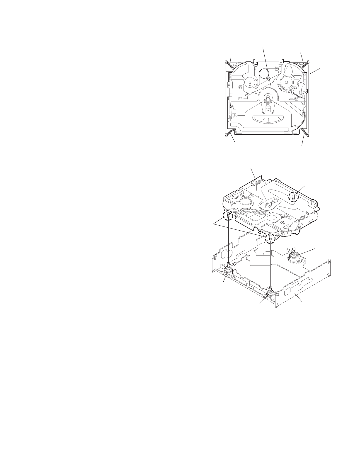
3.2.4 Removing the chassis unit
r
(See Figs.8 and 9)
• Prior to performing the following procedure, remove the top
cover and connector board.
(1) Remove the two suspension springs (L) and (R) attaching
the chassis unit to the frame.
CAUTION:
• The shape of the suspension spring (L) and (R) are different. Handle them with care.
• When reassembling, make sure that the three shafts
on the underside of the chassis unit are inserted to the
dampers certainly.
Suspension spring (R)
Chassis unit
Suspension spring (L)
Frame
Suspension spring (R)
Chassis unit
Shafts
Damper
Damper
Suspension spring (L)
Fig.8
Shaft
Dampe
Frame
Fig.9
(No.MA204)1-13
Page 14

3.2.5 Removing the clamper assembly
(See Figs.10 and 11)
• Prior to performing the following procedure, remove the top
cover.
(1) Remove the clamper arm spring.
(2) Move the clamper assembly in the direction of the arrow to
release the two joints d.
Clamper arm
spring
Joint d
Joint d
Clamper assembly
Fig.10
Clamper arm spring
Chassis rivet
assembly
Joint d
Clamper
assembly
Chassis rivet assembly
Fig.11
Joint d
1-14 (No.MA204)
Page 15

3.2.6 Removing the loading / feed motor assembly
(See Figs.12 and 13)
• Prior to performing the following procedure, remove the top
cover, connector board and chassis unit.
(1) Remove the screw C and move the loading / feed motor
assembly in the direction of the arrow to remove it from the
chassis rivet assembly.
(2) Disconnect the wire from the loading / feed motor assembly
if necessary.
CAUTION:
When reassembling, connect the wire from the loading /
feed motor assembly to the flame as shown in Fig.12.
Loading / feed motor assembly
Fig.12
Loading / feed motor assembly
C
Fig.13
(No.MA204)1-15
Page 16

3.2.7 Removing the pickup unit
(See Figs.14 to 18)
• Prior to performing the following procedure, remove the top
cover, connector board and chassis unit.
(1) Remove the screw D and pull out the pu. shaft holder from
the pu. shaft.
(2) Remove the screw E attaching the feed sw. holder.
(3) Move the part e of the pickup unit upward with the pu. shaft
and the feed sw. holder, then release the joint f of the feed
sw. holder in the direction of the arrow. The joint g of the
pickup unit and the feed rack is released, and the feed sw.
holder comes off.
(4) Remove the pu. shaft from the pickup unit.
(5) Remove the screw F attaching the feed rack to the pickup
unit.
3.2.8 Reattaching the pickup unit
(See Figs.14 to 17)
(1) Reattach the feed rack to the pickup unit using the screw F.
(2) Reattach the feed sw. holder to the feed rack while setting
the joint g to the slot of the feed rack and setting the part f
of the feed rack to the switch of the feed sw. holder correctly.
(3) As the feed sw. holder is temporarily attached to the pickup
unit, set to the gear of the joint g and to the bending part of
the chassis (joint h) at a time.
CAUTION:
Make sure that the part i on the underside of the feed
rack is certainly inserted to the slot j of the change lock
lever.
(4) Reattach the feed sw. holder using the screw E.
(5) Reattach the pu. shaft to the pickup unit. Reattach the pu.
shaft holder to the pu. shaft using the screw D.
Feed sw. holder
Joint f
Joint g
Feed sw.
holder
Part e
Feed rack
Part i
E
Pickup unit
Slot j
F
Fig.15
Pu. shaft
Pickup unit
Joint f
Joint h
Fig.16
Feed rack
Pickup unit
Feed sw. holder
D
Pu. shaft
holder
Pu. shaft
D
Pu. shaft holder
1-16 (No.MA204)
Pickup unit
Fig.14
Part e
E
Joint g
Feed rack
Fig.17
Pickup unit
Joint g
Joint f
Feed sw. holder
Fig.18
Page 17

3.2.9 Removing the trigger arm
r
(See Figs.19 and 20)
• Prior to performing the following procedure, remove the top
cover, connector board and clamper unit.
(1) Turn the trigger arm in the direction of the arrow to release
the joint k and pull out upward.
CAUTION:
When reassembling, insert the part m and n of the trigger
arm into the part p and q at the slot of the chassis rivet
assembly respectively and join the joint k at a time.
Chassis rivet assembly
Trigger arm
Chassis rivet
assembly
Joint k
Trigger arm
Fig.19
Part p
Part q
Part m
Part n
3.2.10 Removing the top plate assembly
(See Fig.21)
• Prior to performing the following procedure, remove the top
cover, connector board, chassis unit, and clamper assembly.
(1) Remove the screw H.
(2) Move the top plate assembly in the direction of the arrow to
release the two joints r.
(3) Unsolder the wire marked s if necessary.
H
Fig.20
Top plate assembly
Joints
s
Fig.21
(No.MA204)1-17
Page 18

3.2.11 Removing the mode sw. / select lock arm
(See Figs.22 and 23)
• Prior to performing the following procedure, remove the top
plate assembly.
(1) Bring up the mode sw. to release from the link plate (joint t)
and turn in the direction of the arrow to release the joint u.
(2) Unsolder the wire of the mode sw. marked s if necessary.
(3) Turn the select lock arm in the direction of the arrow to re-
lease the two joints v.
(4) The select lock arm spring comes off the select lock arm at
the same time.
Top plate
Link plate
Joint u
Joint t
s
Fig.22
Select lock arm
Select lock arm
Mode sw.
Select lock arm
Top plate
Hook w
Select lock
arm spring
Link plate
Joints v
Fig.23
1-18 (No.MA204)
Page 19

3.2.12 Reassembling the mode sw. / select lock arm
(See Figs.24 to 26)
REFERENCE:
Reverse the above removing procedure.
(1) Reattach the select lock arm spring to the top plate and set
the shorter end of the select lock arm spring to the hook w
on the top plate.
(2) Set the other longer end of the select lock arm spring to the
boss x on the underside of the select lock arm, and join the
select lock arm to the slots (joint v). Turn the select lock
arm as shown in the figure.
(3) Reattach the mode sw. while setting the part t to the first
peak of the link plate gear, and join the joint u.
CAUTION:
When reattaching the mode sw., check if the points y and
z are correctly fitted and if each part operates properly.
Select lock arm spring
Hook w
Joint v
Joint v
Select lock arm
Boss x
Fig.24
Joint t
Point y
Link plate
Point z
Link plate
Fig.25
Mode sw.
Select
lock arm
Joint t
Joint u
Fig.26
(No.MA204)1-19
Page 20

3.2.13 Removing the select arm R / link plate
(See Figs.27 and 28)
• Prior to performing the following procedure, remove the top
plate assembly.
(1) Bring up the select arm R to release from the link plate
(joint a') and turn as shown in the figure to release the two
joints b' and joint c'.
(2) Move the link plate in the direction of the arrow to release
the joint d'. Remove the link plate spring at the same time.
REFERENCE:
Before removing the link plate, remove the mode sw..
Select arm R
Joint b'
Link plate spring
Joint c'
Joint a'
Link plate
Joint b'
Fig.27
Joint r
3.2.14 Reattaching the Select arm R / link plate
(See Figs.29 and 30)
REFERENCE:
Reverse the above removing procedure.
(1) Reattach the link plate spring.
(2) Reattach the link plate to the link plate spring while joining
them at joint d'.
(3) Reattach the joint a' of the select arm R to the first peak of
the link plate while joining the two joints b' with the slots.
Then turn the select arm R as shown in the figure. The top
plate is joined to the joint c'.
CAUTION:
When reattaching the select arm R, check if the points e'
and f' are correctly fitted and if each part operates properly.
Top plate
Select arm R
Joint b'
Joint d'
Link plate
Fig.28
Link plate spring
Joint c'
Joint d'
Joint b'
Joint a'
Fig.29
1-20 (No.MA204)
Joint a'
Point e'
Link plate
Point f'
Fig.30
Page 21

3.2.15 Removing the loading roller assembly
(See Figs.31 to 33)
• Prior to performing the following procedure, remove the
clamper assembly and top plate assembly.
(1) Push inward the loading roller assembly on the gear side
and detach it upward from the slot of the joint g' of the lock
arm rivet assembly.
(2) Detach the loading roller assembly from the slot of the joint
h' of the lock arm rivet assembly.
Roller guide
spring
Part k'
Loading roller assembly
Loading roller assembly
The roller guide comes off the gear section of the loading
roller assembly.
Remove the roller guide and the HL washer from the shaft
of the loading roller assembly.
(3) Remove the screw J attaching the lock arm rivet assembly.
(4) Push the shaft at the joint i' of the lock arm rivet assembly
inward to release the lock arm rivet assembly from the slot
of the L side plate.
(5) Extend the lock arm rivet assembly outward and release
the joint j' from the boss of the chassis rivet assembly. The
roller guide springs on both sides come off at the same
time.
CAUTION:
When reassembling, reattach the left and right roller
guide springs to the lock arm rivet assembly before reattaching the lock arm rivet assembly to the chassis rivet
assembly. Make sure to fit the part k' of the roller guide
spring inside of the roller guide. (Refer to Fig.34.)
Roller guide
HL washer
Loading roller assembly
Roller guide
Chassis rivet assembly
J
Roller guide
spring
Fig.32
Boss
L side plate
Roller guide spring
Joint h'
Roller guide spring
Loading roller assembly
Joint g'
Lock arm rivet assembly
Fig.31
Roller guide spring
Roller guide spring
Lock arm rivet assembly
Lock arm rivet assembly
Joint i'
Part j'
Fig.33
Roller guide
HL washer
Roller shaft assembly
Loading roller
Roller guide spring
Fig.34
(No.MA204)1-21
Page 22

3.2.16 Removing the loading gear 5, 6 and 7
(See Figs.35 and 36)
• Prior to performing the following procedure, remove the top
cover, chassis unit, pickup unit and top plate assembly.
(1) Remove the screw K attaching the loading gear bracket.
The loading gear 6 and 7 come off the loading gear bracket.
(2) Pull out the loading gear 5.
K
Loading gear bracket
K
Loading gear 6
Loading gear 5
Loading gear 3
Fig.35
Loading gear bracket
Loading gear 5
Loading gear 6
Loading gear 7
Fig.36
1-22 (No.MA204)
Page 23

3.2.17 Removing the gears
(See Figs.37 to 40)
• Prior to performing the following procedure, remove the top
cover, chassis unit, top plate assembly and pickup unit.
• Pull out the loading gear 3. (See Fig.35.)
(1) Pull out the feed gear.
(2) Move the loading plate assembly in the direction of the ar-
row to release the L side plate from the two slots m' of the
chassis rivet assembly. (See Fig.37.)
(3) Detach the loading plate assembly upward from the chas-
sis rivet assembly while releasing the joint n'. Remove the
slide hook and loading plate spring from the loading plate
assembly.
(4) Pull out the loading gear 2 and remove the change lock le-
ver.
(5) Remove the E ring and washer attaching the changer gear
2.
(6) The changer gear 2, change gear spring and adjusting
washer come off.
(7) Remove the loading gear 1.
(8) Move the change plate rivet assembly in the direction of the
arrow to release from the three shafts of the chassis rivet
assembly upward. (See Fig.38.)
(9) Detach the loading gear plate rivet assembly from the shaft
of the chassis rivet assembly upward while releasing the
joint p'. (See Figs.38 and 40.)
(10) Pull out the loading gear 4.
Change plate
rivet assembly
Shafts
E ring
Loading plate assembly
Loading plate spring
Joint p'
Loading gear 4
Loading gear plate
rivet assembly
Shaft
Loading gear 2
Loading gear 1
Chassis rivet assembly
Change gear 2
Fig.38
Joint n'
Slide hook
Feed gear
Fig.37
Slot m'
L side plate
Loading plate assembly
Joint n'
Slot m'
Chassis rivet assembly
Chassis rivet assembly
E ring
Washer
Change gear 2
Change gear spring
Adjusting washer
Change plate
rivet assembly
Chassis rivet assembly
L side plate
Slot m'
Slot m'
Fig.39
Loading gear 1
Loading gear 2
Change lock lever
Loading gear 4
Loading gear plate rivet assembly
Fig.40
(No.MA204)1-23
Page 24

3.2.18 Removing the turn table / spindle motor
(See Figs.41 and 42)
• Prior to performing the following procedure, remove the top
cover, connector board, chassis unit and clamper assembly.
(1) Remove the two screws L attaching the spindle motor as-
sembly through the slot of the turn table on top of the body.
(2) Unsolder the wire on the connector board if necessary.
Turn table
L
Fig.41
L
Turn table
1-24 (No.MA204)
Spindle motor
Fig.42
Page 25

SECTION 4
ADJUSTMENT
4.1 Adjustment method
Test instruments required for adjustment
(1) Digital oscilloscope (100MHz)
(2) Electric voltmeter
(3) Digital tester
(4) Tracking offset meter
(5) Test Disc JVC :CTS-1000
(6) Extension cable for check
EXTSH002-22P × 1
Standard volume position
Balance and Bass &Treble volume : lndication"0"
Loudness : OFF
How to connect the extension cable for adjusting
Caution:
Be sure to attach the heat sink and rear bracket onto the power amplifier IC and regulator IC respectively, before supply the power.
If voltage is applied without attaching these parts, the power amplifier IC and regulator IC will be destroyed by heat.
Standard measuring conditions
Power supply voltage DC14.4V(11 to 16V)
Load impedance 20KΩ(2 Speakers connection)
Output Level Line out 2.0V (Vol. MAX)
Dummy load
Exclusive dummy load should be used for AM,and FM. For FM
dummy load,there is a loss of 6dB between SSG output and
antenna input.The loss of 6dB need not be considered since
direct reading of figures are applied in this working standard.
Heat sink
Extension cable
EXTSH002-22P
Rear bracket
(No.MA204)1-25
Page 26

5.1 Feed section
SECTION 5
TROUBLESHOOTING
Is the voltage output at
IC521 pin 40, 5V or 0V?
YES
Is 4V present at both
sides of the feed motor?
YES
Check the feed motor.
5.2 Focus section
5.3 Spindle section
NO
Is the wiring for IC521
pin 40 correct?
NO
Is 6V or 2V present at
IC561 pins 4 and 5?
Check IC561.
When the lens is
moving:
Does the S-search
waveform appear at
IC561 pins 8 and 9?
NO
NO
YES
4V
YES
YES
Is 5V present at IC561
pins 3,12 and 21?
Check the vicinity of
IC521.
Check the feed motor
connection wiring.
NO
Check the circuits in
the vicinity of IC561
pins 15 and 16.
Check the pickup and
its connections.
NO
Check CD 8V.
YES
YES
Is the disk rotated?
YES
Does the RF signal
appear at RF test point?
YES
Is the RF waveform
at RF test point
distorted?
YES
Proceed to the Tracking
section.
5.4 Tracking section
When the disc is rotated
at first:
Is the tracking error
signal output at
TE test point?
NO
Is 4V present between
IC561 pins 6 and 7?
Check the spindle motor
and its wiring.
NO
Check the circuits in
the vicinity of IC501
pin 19 or the pickup.
NO
NO
Approx. 1.2V
NO
YES
Check the circuits in
the vicinity of IC501
pins 2 to 12.
Is 4V present at IC521
pin 41?
YES
Check the vicinity of
IC561.
NO
Check the pickup and
its connections.
NO
Check IC521.
1-26 (No.MA204)
YES
Check IC521.
Page 27

5.5 Signal processing section
Is the sound output from
both channels (L, R)?
Normal
YES
No sound from either
channel.
YES
Is 9V present at IC161 pin
31?
YES
NONO
Compare the L-ch and
R-ch to locate the
defctive point.
NO
Check the viciniyt of the
IC901 audio power
supply.
Is the audio signal
(including sampling output
components) output to
IC571 pins 1 and 7 during
playback?
YES
Is the audio signal output
at IC161 pins 3 and 30
during playback?
YES
Check the power amp.
IC301.
NO
NO
Check IC571 and its
peripheral circuits.
Check IC161 and its
peripheral circuits.
(No.MA204)1-27
Page 28

5.6 Maintenance of laser pickup
(1) Cleaning the pick up lens
Before you replace the pick up, please try to clean the lens
with a alcohol soaked cotton swab.
(2) Life of the laser diode
When the life of the laser diode has expired, the following
symptoms will appear.
• The level of RF output (EFM output: amplitude of eye
pattern) will be low.
5.7 Replacement of laser pickup
Turn off the power switch and,disconnect the
power cord from the ac outlet.
Replace the pickup with a normal one. (Refer
to "Removing the pickup unit" on the previous page.)
Is RF output
1.0 0.4Vp-p?
NO
Replace it.
YES
OK
(3) Semi-fixed resistor on the APC PC board
The semi-fixed resistor on the APC printed circuit board
which is attached to the pickup is used to adjust the laser
power.Since this adjustment should be performed to match
the characteristics of the whole optical block, do not touch
the semi-fixed resistor.
If the laser power is lower than the specified value, the laser diode is almost worn out, and the laser pickup should
be replaced. If the semi-fixed resistor is adjusted while the
pickup is functioning normally, the laser pickup may be
damaged due to excessive current.
Plug the power cord in, and turn the power on.
At this time, check that the laser emits for about
seconds and the objective lens moves up and down.
Note: Do not observe the laser beam directly.
Play a disc.
Check the eye-pattern at
RF test point.
Finish.
1-28 (No.MA204)
Page 29

5.8 16 PIN CORD DIAGRAM
10
12
14
16
NC
YL
NC
BK
NC
NC
BL/WH
RD
9
11
13
15
1
2
3
4
5
6
7
8
VI
VI/BK
GY
GY/BK
WH
WH/BK
GN
GN/BK
2
4
6
8
VI/BK
GY/BK
WH/BK
GN/BK
RR+
RR-
FR+
FR-
FL+
FL-
RL+
RL-
VI
GY
WH
GN
1
3
5
BK
RD
BL
WH
Black
Red
Blue
White
7
GN
VI
GY
YL
Green
Violet
Gray
Yellow
RR
FR
FL
RL
REMOTE
YL
12
BL/WH
13
RD
15
16
BK
Rear Right
Front Right
Front Left
Rear Left
Remote
MEMORY
REMOTE
ACC
GND
ANT
ACC
TEL
GND
MEMORY
MEMORY BACKUP
DIRECT TO BATTERY
+12Volt
ACC + 12Volt
GROUND
Auto Antenna
ACC Line
Telephone Muting
Ground
Memory Backup Battery+
(No.MA204)1-29
Page 30

Victor Company of Japan, Limited
AV & MULTIMEDIA COMPANY CAR ELECTRONICS CATEGORY 10-1,1chome,Ohwatari-machi,Maebashi-city,371-8543,Japan
(No.MA204)
Printed in Japan
VPT
Page 31

CD RECEIVER
RECEPTEUR CD
KD-S1501/KD-G153/
KD-G152/KD-G151
For canceling the display demonstration, see page 7.
Pour annuler la démonstration des affichages, référez-vous à la page 7.
ENGLISH
FRANÇAIS
For installation and connections, refer to the separate manual.
Pour l’installation et les raccordements, se référer au manuel séparé.
INSTRUCTIONS
MANUEL D’INSTRUCTIONS
GET0287-003B
[EX/EU]
Page 32

Thank you for purchasing a JVC product.
Please read all instructions carefully before operation, to ensure your complete understanding and to
obtain the best possible performance from the unit.
ENGLISH
IMPORTANT FOR LASER PRODUCTS
1. CLASS 1 LASER PRODUCT
2. CAUTION: Do not open the top cover. There are no user serviceable parts inside the unit; leave
all servicing to qualified service personnel.
3. CAUTION: Visible and invisible laser radiation when open and interlock failed or defeated.
Avoid direct exposure to beam.
4. REPRODUCTION OF LABEL: CAUTION LABEL, PLACED OUTSIDE THE UNIT.
Warning:
If you need to operate the receiver while
driving, be sure to look ahead carefully or
you may be involved in a traffic accident.
How to forcibly eject a disc
If a disc cannot be recognized by the
receiver or cannot be ejected, ejects the disc
as follows.
How to reset your unit
• If this does not work, reset your receiver.
• Be careful not to drop the disc when it
• This will reset the microcomputer. Your
preset adjustments will also be erased.
• If a disc is loaded, it will eject. Be careful
not to drop the disc.
Note: Only for [EX] model users in UK and European countries
For security reasons, a numbered ID card is provided with this receiver, and the same ID number is
imprinted on the receiver’s chassis. Keep the card in a safe place, as it will help the authorities to
identify your receiver if stolen.
2
ejects.
Page 33

Contents
How to reset your unit ........................... 2
How to forcibly eject a disc ................... 2
How to read this manual ........................ 4
How to use the MODE button ............... 4
Control panel — KD-S1501/
KD-G153/KD-G152/KD-G151 ....... 5
Parts identification ................................. 5
Getting started ....................... 6
Basic operations .................................. 6
Canceling the display demonstrations ... 7
Setting the clock .................................... 7
Radio operations ................... 8
Listening to the radio ........................... 8
Storing stations in memory .................... 9
Listening to a preset station ................... 9
FM RDS operations ................. 10
Searching for your favorite FM RDS
programme
Storing your favorite programmes ......... 11
Using the standby receptions ................. 11
Tracking the same programme
—Network-Tracking Reception ........ 12
....................................... 10
Disc operations ...................... 13
Playing a disc ..................................... 13
Selecting the playback modes ................ 14
Sound adjustments ................ 15
Selecting preset sound modes
(C-EQ: custom equalizer) .................. 15
Adjusting the sound ............................... 16
General settings — PSM ......... 17
Basic procedure ..................................... 17
Detaching the control
panel .................................. 19
Maintenance .......................... 20
More about this receiver ........ 21
Troubleshooting ..................... 22
Specifications ......................... 23
ENGLISH
For safety....
• Do not raise the volume level too much, as
this will block outside sounds, making driving
dangerous.
• Stop the car before performing any
complicated operations.
Temperature inside the car....
If you have parked the car for a long time in
hot or cold weather, wait until the temperature
in the car becomes normal before operating the
unit.
3
Page 34

How to read this manual
The following methods are used to make the
explanations simple and easy-to-understand:
• Some related tips and notes are explained in
ENGLISH
“More about this receiver” (see page 21).
• Button operations are mainly explained with
the illustrations as follows:
Press briefly.
Press repeatedly.
Press either one.
Press and hold until
your desired response
begins.
How to use the MODE button
If you press MODE, the receiver goes into
functions mode, then the number buttons work
as different function buttons.
Ex.: When number button 2 works as
MO (monaural) button.
Time countdown indicator
To use these buttons for original functions
again after pressing MODE, wait for
5 seconds without pressing any of these buttons
until the functions mode is cleared.
• Pressing MODE again also clears the
functions mode.
Press and hold both
buttons at the same
time.
4
Caution for DualDisc playback
• The Non-DVD side of a “DualDisc” does
not comply with the “Compact Disc Digital
Audio” standard. Therefore, the use of NonDVD side of a DualDisc on this product may
not be recommended.
Page 35

Control panel — KD-S1501/KD-G153/KD-G152/KD-G151
Parts identification
Display window
1 +/– buttons
2 DISP (display) button
3 Loading slot
4 Display window
5 MODE button
6 0 (eject) button
7
¢/4 buttons
8
9 SEL (select) button
p EQ (equalizer) button
q MO (monaural) button
w SSM (Strong-station Sequential Memory)
e CD button
r FM/AM button
t RPT (repeat) button
y RND (random) button
u T/P (traffic programme/programme type)
i
o Number buttons
(standby/on/attenuator) button
button
button
(control panel release) button
Display window
; Tuner reception indicators
MO (monaural), ST (stereo)
a RDS indicators
TP, PTY, AF, REG
s CD indicator
d RND
f RPT (repeat) indicator
g LOUD (loudness) indicator
h EQ (equalizer) indicator
j Sound mode (C-EQ: custom equalizer)
indicators
ROCK, CLASSIC, POPS, HIP HOP, JAZZ,
USER
•
k Main display
l Source display
Volume level indicator
(disc random) indicator
also works as the time countdown
indicator.
ENGLISH
5
Page 36

Getting started
ENGLISH
Basic operations
~
Ÿ
You cannot select “CD” as the playback
source if there is no disc in the loading
slot.
!
Volume level appears.
To drop the volume in a moment (ATT)
To restore the sound, press it
again.
To turn off the power
Caution on volume setting:
Discs produce very little noise compared
with other sources. Lower the volume
before playing a disc to avoid damaging
the speakers by the sudden increase of the
output level.
Volume level indicator
⁄ Adjust the sound as you want.
(See pages 15 and 16.)
6
Page 37

Canceling the display
demonstrations
If no operations are done for about 20 seconds,
display demonstration starts.
[Initial: DEMO ON]—see page 17.
1
2
Setting the clock
1
2
Set the hour, minute, and clock
system.
1 Select “CLOCK H” (hour), then
adjust the hour.
2 Select “CLOCK M” (minute),
then adjust the minute.
3 Select “24H/12H,” then select
“24H” (hour) or “12H” (hour).
ENGLISH
3
Finish the procedure.
4
To activate the display demonstration
In step 3 above...
3 Finish the procedure.
To check the current clock time when the
power is turned off
7
Page 38

Radio operations
Listening to the radio
ENGLISH
~
Lights up when receiving an FM stereo
broadcast with sufficient signal strength.
Selected band appears.
2 Select the desired station frequencies.
When an FM stereo broadcast is hard to
receive
1
Ÿ Start searching for a station.
When a station is received, searching
stops.
To stop searching, press the same
button again.
To tune in to a station manually
In step Ÿ above...
1
8
2
Lights up when monaural mode is activated.
Reception improves, but stereo effect will
be lost.
To restore the stereo effect, repeat the same
procedure. “MONO OFF” appears and the MO
indicator goes off.
Page 39

Storing stations in memory
You can preset six stations for each band.
FM station automatic presetting —
SSM (Strong-station Sequential
Memory)
Select the FM band (FM1 – FM3)
1
you want to store into.
2
2
ENGLISH
3
Preset number flashes for a while.
3
“SSM” flashes, then disappears when
automatic presetting is over.
Local FM stations with the strongest signals are
searched and stored automatically in the FM
band.
Manual presetting
Ex.: Storing FM station of 92.5 MHz into the
preset number 4 of the FM1 band.
1
Listening to a preset station
1
Select the preset station (1 – 6) you
2
want.
To check the current clock time while
listening to an FM (non-RDS) or AM station
• For FM RDS stations, see page 12.
9
Page 40

FM RDS operations
Searching for your favorite FM RDS programme
ENGLISH
You can tune in to a station broadcasting your
favorite programme by searching for a PTY code.
~
! Start searching for your favorite
programme.
The last selected PTY code appears.
Ÿ Select one of your favorite
programme type.
or
Select one of the twenty-nine PTY
codes.
Ex.: When “ROCK M” is selected
10
If there is a station broadcasting a
programme of the same PTY code as
you have selected, that station is tuned
in.
PTY codes
NEWS, AFFAIRS, INFO, SPORT,
EDUCATE, DRAMA, CULTURE,
SCIENCE, VARIED, POP M (music),
ROCK M (music), EASY M (music),
LIGHT M (music), CLASSICS, OTHER
M (music), WEATHER, FINANCE,
CHILDREN, SOCIAL, RELIGION,
PHONE IN, TRAVEL, LEISURE, JAZZ,
COUNTRY, NATION M (music), OLDIES,
FOLK M (music), DOCUMENT
Page 41

What you can do with RDS
RDS (Radio Data System) allows FM
stations to send an additional signal along
with their regular programme signals.
By receiving the RDS data, this receiver can
do the following:
•
Programme Type (PTY) Search (see page 10)
• Standby Reception of Traffic
Announcement —TA (see the following) or
your favorite programme (PTY) (see pages
12 and 18)
•
Tracing the same programme automatically
—Network-Tracking Reception (see page 12)
• Programme Search (see page 18)
Storing your favorite programmes
You can store six favorite programme types.
3 Repeat steps 1 and 2 to store
other PTY codes into other preset
numbers.
ENGLISH
4 Finish the procedure.
Using the standby receptions
TA Standby Reception
TA Standby Reception allows the receiver to
switch temporarily to Traffic Announcement
(TA) from any source other than AM.
The volume changes to the preset TA volume
level (see page 18).
Preset programme types in the number buttons
(1 – 6):
1 Perform steps ~ and Ÿ on page 10 to
select a PTY code.
2 Select the preset number (1 – 6) you
want to store into.
Ex.: When “ROCK M” is selected
To activate TA Standby Reception
The TP indicator either
lights up or flashes.
• If the TP indicator lights up, TA Standby
Reception is activated.
• If the TP indicator flashes, TA Standby
Reception is not yet activated. (This occurs
when you are listening to an FM station
without the RDS signals required for TA
Standby Reception.)
To activate TA Standby Reception, tune in to
another station providing these signals. The
TP indicator will stop flashing and remain lit.
To deactivate the TA Standby Reception
The TP indicator goes off.
11
Page 42

PTY Standby Reception
PTY Standby Reception allows the receiver
to switch temporarily to your favorite PTY
programme from any source other than AM.
ENGLISH
To activate and select your favorite PTY
code for PTY Standby Reception, see page
18.
The PTY indicator either lights up or flashes.
• If the PTY indicator lights up, PTY Standby
Reception is activated.
• If the PTY indicator flashes, PTY Standby
Reception is not yet activated.
To activate PTY Standby Reception, tune in
to another station providing these signals. The
PTY indicator will stop flashing and remain
lit.
To deactivate the PTY Standby Reception,
select “OFF” for the PTY code (see page 18).
The PTY indicator goes off.
Tracking the same programme—
Network-Tracking Reception
When driving in an area where FM reception
is not sufficient enough, this receiver
automatically tunes in to another FM RDS
station of the same network, possibly
broadcasting the same programme with stronger
signals (see the illustration below).
When shipped from the factory, NetworkTracking Reception is activated.
To change the Network-Tracking Reception
setting, see page 18.
Programme A broadcasting on different
frequency areas (01 – 05)
12
To check the current clock time while
listening to an FM RDS station
Page 43

Disc operations
Playing a disc
ENGLISH
All tracks will be played repeatedly until you
change the source or eject the disc.
Total playing time of
the inserted disc
Elapsed playing
time
Total track number
of the inserted disc
Current track
number
To stop play and eject the disc
To fast-forward or reverse the track
Fast-forwards.
Reverses.
To go to the next or previous tracks
To the following
tracks.
To the beginning of the current track, then
the previous tracks.
To go to a particular track directly
To select a number from 01 – 06:
To select a number from 07 – 12:
13
Page 44

Prohibiting disc ejection
You can lock a disc in the loading slot.
To check the current clock time while
listening to a disc
ENGLISH
To cancel the prohibition, repeat the same
procedure.
Selecting the playback modes
You can use only one of the following playback modes at a time.
1
2 Select your desired playback mode.
14
Repeat play
Ex.: When “TRK RPT” is selected
Random play
Ex.: When “DISC RND” is selected
Mode Plays repeatedly
TRK RPT: The current track.
• RPT lights up.
RPT OFF: Cancels.
Mode Plays at random
DISC RND: All tracks of the current disc.
• RND
RND OFF: Cancels.
lights up.
Page 45

Sound adjustments
Selecting preset sound modes (C-EQ: custom equalizer)
ENGLISH
You can select a preset sound mode suitable to
the music genre.
~
Ÿ
Ex.: When “ROCK” is selected
Indication pattern for each sound mode:
Indication For:
USER (Flat sound) 00 00 OFF
ROCK Rock or
disco music
CLASSIC Classical
music
POPS Light music +04 +01 OFF
HIP HOP Funk or rap
music
JAZZ Jazz music +02 +03 OFF
1
*
BAS: Bass
2
*
TRE: Treble
3
*
LOUD: Loudness
1
TRE
*
2
LOUD
*
BAS
+03 +01 ON
+01 –02 OFF
+02 00 ON
Preset values
3
*
15
Page 46

Adjusting the sound
You can adjust the sound characteristics to your
preference.
ENGLISH
1
Ex.: When “TRE” is selected
2
Indication pattern changes as
you adjust the level.
Indication To do: Range
BAS*1
(bass)
TRE*
(treble)
FAD*
(fader)
BAL
(balance)
LOUD*
(loudness)
VOL*
(volume)
Adjust the bass. –06 (min.)
1
Adjust the treble. –06 (min.)
2
Adjust the front
and rear speaker
balance.
Adjust the left
and right speaker
balance.
1
Boost low and
high frequencies
to produce a wellbalanced sound at
low volume level.
3
Adjust the volume. 00 (min.) to
to
+06 (max.)
to
+06 (max.)
R06 (Rear
only)
to
F06 (Front
only)
L06 (Left
only)
to
R06 (Right
only)
LOUD ON
LOUD OFF
30 or 50
(max.)*
J
4
16
*1 When you adjust the bass, treble, or
loudness, the adjustment you have made is
stored for the currently selected sound mode
(C-EQ) including “USER.”
2
*
If you are using a two-speaker system, set
the fader level to “00.”
3
*
Normally the +/– buttons work as the volume
control. So you do not have to select “VOL”
to adjust the volume level.
4
*
Depending on the amplifier gain control
setting. (See page 18 for details.)
Page 47

General settings — PSM
Basic procedure
3 Adjust the PSM item selected.
You can change PSM (Preferred Setting Mode)
items listed on the table that follows.
1
4 Repeat steps 2 and 3 to adjust the
other PSM items if necessary.
2
Select a PSM item.
Ex.: When you select “AMP GAIN”
Indications Selectable settings, [reference page]
5 Finish the procedure.
ENGLISH
DEMO
Display demonstration
CLOCK H
Hour adjustment
CLOCK M
Minute adjustment
24H/12H
24 hours or 12 hours time
display
CLK ADJ
Automatic clock setting
DEMO ON: [Initial]; Display demonstration will be activated
automatically if no operation is done for about
20 seconds, [7].
DEMO OFF: Cancels.
0 – 23 (1 – 12), [7]
[Initial: 0 (0:00)]
00 – 59, [7]
[Initial: 00 (0:00)]
12H O 24H, [7]
[Initial: 24H]
AUTO: [Initial]; The built-in clock is automatically adjusted
using the CT (clock time) data in the RDS signal.
OFF: Cancels.
To be continued....
17
Page 48

Indications Selectable settings, [reference page]
AF-REG
Alternative frequency/
ENGLISH
regionalization reception
PTY-STBY
PTY standby
TA VOL
Traffic announcement
volume
P-SEARCH
Programme search
ILL SW*
2
Illumination switch
2
TEL*
Telephone muting
When the received signals from the current station become weak....
AF: [Initial]; Switches to another station (the programme
may differ from the one currently received), [12].
• The AF indicator lights up.
AF REG: Switches to another station broadcasting the same
programme.
• The AF and REG indicators light up.
OFF: Cancels.
Activates PTY Standby Reception with one of the 29 PTY codes,
[12].
OFF [Initial]
[Initial: VOL 20]; VOL 00 – VOL 30 or 50*
=
29 PTY codes, [10] = (back to the beginning)
1
, [11]
ON: Using the AF data, the receiver tunes in to another
frequency broadcasting the same programme as the
original preset RDS station is if the preset station
signals are not sufficient.
OFF: [Initial]; Cancels.
You can select the button illumination according to your
preference.
RED O GREEN
[Initial: RED]
MUTING 1/MUTING 2: Select either one which mutes the
sounds while using the cellular phone.
OFF: [Initial]; Cancels.
AMP GAIN
Amplifier gain control
1
*
Depends on the amplifier gain control.
2
*
Only for KD-S1501.
18
You can change the maximum volume level of this receiver.
LOW PWR: VOL 00 – VOL 30 (Select this if the maximum
power of the speaker is less than 45 W to prevent
them from damaging the speaker.)
HIGH PWR: [Initial]; VOL 00 – VOL 50
Page 49

Detaching the control panel
When detaching or attaching the control panel,
be careful not to damage the connectors on
the back of the control panel and on the panel
holder.
Detaching the control panel
Before detaching the control panel, be sure to
turn off the power.
Attaching the control panel
ENGLISH
19
Page 50

Maintenance
How to clean the connectors
Frequent detachment will deteriorate the
connectors.
To minimize this possibility, periodically wipe
ENGLISH
the connectors with a cotton swab or cloth
moistened with alcohol, being careful not to
damage the connectors.
Connector
Moisture condensation
Moisture may condense on the lens inside the
CD player in the following cases:
• After starting the heater in the car.
• If it becomes very humid inside the car.
Should this occur, the CD player may
malfunction. In this case, eject the disc and
leave the receiver turned on for a few hours
until the moisture evaporates.
To keep discs clean
A dirty disc may not play correctly.
If a disc does become dirty, wipe
it with a soft cloth in a straight line
from center to edge.
• Do not use any solvent (for
example, conventional record cleaner, spray,
thinner, benzine, etc.) to clean discs.
To play new discs
New discs may have some rough
spots around the inner and outer
edges. If such a disc is used, this
receiver may reject the disc.
To remove these rough spots, rub the edges
with a pencil or ball-point pen, etc.
How to handle discs
When removing a disc from
its case, press down the center
holder of the case and lift the
disc out, holding it by the
edges.
• Always hold the disc by the edges. Do not
touch its recording surface.
When storing a disc into its case, gently insert
the disc around the center holder (with the
printed surface facing up).
• Make sure to store discs into the cases after
use.
Do not use the following discs:
Warped
disc
20
Center holder
Sticker
Sticker
residue
Disc
Stick-on
label
Page 51

More about this receiver
Basic operations
Turning on the power
• By pressing CD or FM/AM on the receiver,
you can also turn on the power.
Turning off the power
• If you turn off the power while listening to a
disc, disc play will start from where playback
has been stopped previously, next time you
turn on the power.
Tuner operations
Storing stations in memory
• During SSM search...
– All previously stored stations are erased and
stations are stored newly.
– Received stations are preset in No. 1 (lowest
frequency) to No. 6 (highest frequency).
– When SSM is over, the station stored in
No. 1 will be automatically tuned in.
• When storing a station manually, a previously
preset station is erased when a new station is
stored in the same preset number.
FM RDS operations
• Network-Tracking Reception requires two
types of RDS signals—PI (Programme
Identification) and AF (Alternative
Frequency) to work correctly. Without
receiving these data correctly, NetworkTracking Reception will not operate.
• If a Traffic Announcement is received, the
volume level (TA Volume) automatically
changes to the preset level.
Disc operations
General
• This receiver has been designed to reproduce
CDs, and CD-Rs (Recordable)/CD-RWs
(Rewritable) in audio CD (CD-DA) format.
• When a disc has been loaded, selecting “CD”
for the playback source starts disc play.
Inserting a disc
• When a disc is inserted upside down, the disc
automatically ejects.
• Do not insert 8 cm discs (single CD) and
unusual shape discs (heart, flower, etc.) into
the loading slot.
Playing a CD-R or CD-RW
• Use only “finalized” CD-Rs or CD-RWs.
• This receiver can play back multi-session
discs; however, unclosed sessions will be
skipped while playing.
• Some CD-Rs or CD-RWs may not play
back on this receiver because of their disc
characteristics, and for the following causes:
– Discs are dirty or scratched.
– Moisture condensation occurs on the lens
inside the receiver.
– The pickup lens inside the receiver is dirty.
– CD-R or CD-RW on which the files are
written with “Packet Write” method.
– There are improper recording conditions
(missing data, etc.) or media conditions
(stain, scratch, warp, etc.).
• CD-RWs may require a longer readout time
since the reflectance of CD-RWs is lower
than that of regular CDs.
• Do not use the following CD-Rs or CD-RWs:
– Discs with stickers, labels, or protective seal
stuck to the surface.
– Discs on which labels can be directly
printed by an ink jet printer.
Using these discs under high temperatures or
high humidities may cause malfunctions or
damages to discs.
Changing the source
• If you change the source, playback also stops
(without ejecting the disc).
Next time you select “CD” for the playback
source, disc play starts from where it has been
stopped previously.
Ejecting a disc
• If the ejected disc is not removed within
15 seconds, the disc is automatically inserted
again into the loading slot to prevent it from
dust. (Disc will not play this time.)
General settings—PSM
• If you change the “AMP GAIN” setting from
“HIGH PWR” to “LOW PWR” while the
volume level is set higher than “VOL 30,” the
receiver automatically changes the volume
level to “VOL 30.”
ENGLISH
21
Page 52

Troubleshooting
What appears to be trouble is not always serious. Check the following points before calling a service
center.
ENGLISH
• Sound cannot be heard
General
• This receiver does not
• SSM automatic presetting
• Static noise while listening
FM/AM
• Disc automatically ejects. Disc is inserted upside
• CD-R/CD-RW cannot be
• Tracks on the CD-R/
• Disc can be neither played
Symptoms Causes Remedies
from the speakers.
work at all.
does not work.
to the radio.
played back.
CD-RW cannot be
skipped.
back nor ejected.
The volume level is set to
the minimum level.
Connections are incorrect. Check the cords and
The built-in microcomputer
may have functioned
incorrectly due to noise, etc.
Signals are too weak. Store stations manually.
The aerial is not connected
firmly.
down.
CD-R/CD-RW is not
finalized.
Disc is locked. Unlock the disc (see page
Adjust it to the optimum
level.
connections.
Reset the receiver (see page
2).
Connect the aerial firmly.
Insert the disc correctly.
• Insert a finalized CD-R/
CD-RW.
• Finalize the CD-R/
CD-RW with the
component which you
used for recording.
14).
22
Disc playback
• Disc sound is sometimes
interrupted.
• “NO DISC” appears on
the display.
The CD player may have
functioned incorrectly.
You are driving on rough
roads.
Disc is scratched. Change the disc.
Connections are incorrect. Check the cords and
No disc is in the loading
slot.
Disc is inserted incorrectly. Insert the disc correctly.
Eject the disc forcibly (see
page 2).
Stop playback while driving
on rough roads.
connections.
Insert a disc into the loading
slot.
Page 53

Specifications
AUDIO AMPLIFIER SECTION
Maximum Power Output:
Front: 45 W per channel
Rear: 45 W per channel
Continuous Power Output (RMS):
Front: 17 W per channel into 4 Ω, 40 Hz
to 20 000 Hz at no more than 0.8%
total harmonic distortion.
Rear: 17 W per channel into 4 Ω, 40 Hz
to 20 000 Hz at no more than 0.8%
total harmonic distortion.
Load Impedance: 4 Ω (4 Ω to 8 Ω allowance)
Tone Control Range:
Bass: ±10 dB at 100 Hz
Treble: ±10 dB at 10 kHz
Frequency Response: 40 Hz to 20 000 Hz
Signal-to-Noise Ratio: 70 dB
Line-Out Level/Impedance:
2.0 V/20 kΩ load (full scale)
Output Impedance: 1 kΩ
TUNER SECTION
Frequency Range:
FM: 87.5 MHz to 108.0 MHz
AM: (MW) 522 kHz to 1 620 kHz
(LW) 144 kHz to 279 kHz
CD PLAYER SECTION
Type: Compact disc player
Signal Detection System: Non-contact optical
pickup (semiconductor laser)
Number of channels: 2 channels (stereo)
Frequency Response: 5 Hz to 20 000 Hz
Dynamic Range: 96 dB
Signal-to-Noise Ratio: 98 dB
Wow and Flutter: Less than measurable limit
GENERAL
Power Requirement:
Operating Voltage:
DC 14.4 V (11 V to 16 V allowance)
Grounding System: Negative ground
Allowable Operating Temperature:
0°C to +40°C
Dimensions (W × H × D):
Installation Size (approx.):
182 mm × 52 mm × 150 mm
Panel Size (approx.):
188 mm × 58 mm × 11 mm
Mass (approx.):
1.3 kg (excluding accessories)
ENGLISH
[FM Tuner]
Usable Sensitivity: 11.3 dBf (1.0 µV/75 Ω)
50 dB Quieting Sensitivity:
16.3 dBf (1.8 µV/75 Ω)
Alternate Channel Selectivity (400 kHz): 65 dB
Frequency Response: 40 Hz to 15 000 Hz
Stereo Separation: 30 dB
Capture Ratio: 1.5 dB
[MW Tuner]
Sensitivity: 20 µV
Selectivity: 35 dB
[LW Tuner]
Sensitivity: 50 µV
Design and specifications are subject to change
without notice.
23
Page 54

Having TROUBLE with operation?
Please reset your unit
Refer to page of How to reset your unit
Vous avez des PROBLÈMES de fonctionnement?
Réinitialisez votre appareil
Référez-vous à la page intitulée Comment réinitialiser votre appareil
EN, FR
© 2005 Victor Company of Japan, Limited
0405DTSMDTJEIN
Page 55

GET0287-010B
[EX/EU]
KD-S1501/KD-G153/
KD-G152/KD-G151
Installation/Connection Manual
Manuel d’installation/raccordement
0405DTSMDTJEIN
EN, FR
ENGLISH
This receiver is designed to operate on 12 V DC, NEGATIVE ground electrical systems. If
your vehicle does not have this system, a voltage inverter is required, which can be purchased
at JVC IN-CAR ENTERTAINMENT dealers.
Parts list for installation and connection
The following parts are provided for this receiver.
After checking them, please set them correctly.
A / B
Hard case/Control panel
Etui de transport/Panneau de
commande
F
Washer (ø5)
Rondelle (ø5)
G
Lock nut (M5)
Ecrou d’arrêt (M5)
C
Sleeve
Manchon
H
Mounting bolt (M5 x 20 mm)
Boulon de montage (M5 x 20 mm)
INSTALLATION (IN-DASH MOUNTING)
The following illustration shows a typical installation. If you have any questions or require
information regarding installation kits, consult your JVC IN-CAR ENTERTAINMENT dealer or a
company supplying kits.
•
If you are not sure how to install this receiver correctly, have it installed by a qualified technician.
FRANÇAIS
Cet appareil est conçu pour fonctionner sur des sources de courant continu de 12 V à masse
NEGATIVE. Si votre véhicule n’offre pas ce type d’alimentation, il vous faut un convertisseur de tension,
que vous pouvez acheter chez un revendeur d’autoradios JVC.
Liste des pièces pour l’installation et raccordement
Les pièces suivantes sont fournies avec cet appareil.
Après vérification, veuillez les placer correctement.
D
Trim plate
Plaque d’assemblage
I
Rubber cushion
Amortisseur en caoutchouc
E
Power cord
Cordon d’alimentation
J
Handles
Poignées
INSTALLATION (MONTAGE DANS LE TABLEAU DE BORD)
L’illustration suivante est un exemple d’installation typique. Si vous avez des questions ou avez besoin
d’information sur des kits d’installation, consulter votre revendeur d’autoradios JVC ou une compagnie
d’approvisionnement.
• Si l’on n’est pas sûr de pouvoir installer correctement cet appareil, le faire installer par un technicien qualifié.
*1 When you stand the receiver, be
1
*
Lorsque vous mettez l’appareil à la
Removing the receiver / Retrait de l’appareil
Before removing the receiver, release the rear section.
Avant de retirer l’appareil, libérer la section arrière.
Insert the two handles, then
pull them as illustrated so
that the receiver can be
removed.
Insérez les deux poignées, puis
tirez de la façon illustrée de
façon à retirer l’appareil.
careful not to damage the fuse on
the rear.
verticale, faire attention de ne pas
endommager le fusible situé sur l’arrière.
When using the optional stay / Lors
de l’utilisation du hauban en option
Fire wall
Cloison
Dashboard
Tableau de
bord
Install the receiver at an
angle of less than 30˚.
Installez l’appareil avec un
angle de moins de 30˚.
Do the required electrical connections.
Réalisez les connexions électriques.
Stay
(option)
Hauban (en
option)
Screw (option)
Vis (en option)
Bend the appropriate tabs to hold the
sleeve firmly in place.
Tordez les languettes appropriées pour
maintenir le manchon en place.
When installing the receiver without using the sleeve / Lors de
l’installation de l’appareil scans utiliser de manchon
In a Toyota for example, first remove the car radio and install the receiver in its place.
Par exemple dans une Toyota, retirer d’abord l’autoradio et installer l’appareil à la
place.
Flat type screws
(M5 x 8 mm)*
Vis à tête plate
(M5 x 8 mm)*
Pocket
Poche
Note : When installing the receiver on the mounting bracket, make
Remarque : Lors de l’installation de l’appareil sur le support de montage,
Bracket*
Support*
Bracket*
Support*
sure to use the 8 mm-long screws. If longer screws are
used, they could damage the receiver.
s’assurer d’utiliser des vis d’une longueur de 8 mm. Si des vis plus
longues sont utilisées, elles peuvent endommager l’appareil.
* Not included for this
receiver.
* Non fourni avec cet appareil.
Flat type screws
(M5 x 8 mm)*
Vis à tête plate
(M5 x 8 mm)*
PRECAUTIONS on power supply and speaker
connections:
• DO NOT connect the speaker leads of the power cord to
the car battery; otherwise, the receiver will be seriously
damaged.
• BEFORE connecting the speaker leads of the power cord to the
speakers, check the speaker wiring in your car.
PRECAUTIONS sur l’alimentation et la connexion
des enceintes:
• NE CONNECTEZ PAS les fils d’enceintes du cordon
d’alimentation à la batterie; sinon, l’appareil serait
sérieusement endommagé.
• AVANT de connecter les fils d’enceintes du cordon d’alimentation aux
enceintes, vérifiez le câblage des enceintes de votre voiture.
TROUBLESHOOTING
• The fuse blows.
* Are the red and black leads connected correctly?
• Power cannot be turned on.
* Is the yellow lead connected?
• No sound from the speakers.
* Is the speaker output lead short-circuited?
• Sound is distorted.
* Is the speaker output lead grounded?
* Are the “–” terminals of L and R speakers grounded in common?
• Noise interfere with sounds.
* Is the rear ground terminal connected to the car’s chassis using shorter and thicker cords?
• Receiver becomes hot.
* Is the speaker output lead grounded?
* Are the “–” terminals of L and R speakers grounded in common?
• This receiver does not work at all.
* Have you reset your receiver?
EN CAS DE DIFFICULTES
• Le fusible saute.
* Les fils rouge et noir sont-ils racordés correctement?
• L’a p pa r e il n e p e ut pas être mise sous tension.
* Le fil jaune est-elle raccordée?
• Pas de son des enceintes.
* Le fil de sortie d’enceinte est-il court-circuité?
• Le son est déformé.
* Le fil de sortie d’enceinte est-il à la masse?
* Les bornes “–” des enceintes gauche et droit sont-elles mises ensemble à la masse?
• Interférence avec les sons.
La prise arrière de mise à la terre est-elle connectée au châssis de la voiture avec un cordon court et épais?
*
• L’a p pa r e il d e vient chaud.
* Le fil de sortie d’enceinte est-il à la masse?
* Les bornes “–” des enceintes gauche et droit sont-elles mises ensemble à la masse?
• Cet appareil ne fonctionne pas du tout.
* Avez-vous réinitialisé votre appareil?
1
Page 56

ENGLISH FRANÇAIS
ELECTRICAL CONNECTIONS
To prevent short circuits, we recommend that you disconnect the battery’s negative terminal and
make all electrical connections before installing the receiver.
• Be sure to ground this receiver to the car’s chassis again after installation.
Notes:
• Replace the fuse with one of the specified rating. If the fuse blows frequently, consult your JVC
IN-CAR ENTERTAINMENT dealer.
• It is recommended to connect to the speakers with maximum power of more than 45 W (both
at the rear and at the front, with an impedance of 4 Ω to 8 Ω). If the maximum power is less
than 45 W, change “AMP GAIN” setting to prevent the speakers
from being damaged (see page 18 of the INSTRUCTIONS).
• To prevent short-circuit, cover the terminals of the UNUSED
leads with insulating tape.
• The heat sink becomes very hot after use. Be
careful not to touch it when removing this receiver.
Typical connections / Raccordements typiques
A
Dissipateur de chaleur
Before connecting: Check the wiring in the vehicle carefully. Incorrect connection may cause
serious damage to this receiver.
The leads of the power cord and those of the connector from the car body may be different in
color.
1 Connect the colored leads of the power cord in the order specified in the illustration below.
2 Connect the aerial cord.
3 Finally connect the wiring harness to the receiver.
Note: If your vehicle does not have any accessory terminal, move the fuse from the fuse
position 1 (initial position) to fuse position 2, and connect the red lead (A7) to the positive (+)
battery terminal.
• The yellow lead (A4) is not used in this case.
Heat sink
RACCORDEMENTS ELECTRIQUES
Pour éviter tout court-circuit, nous vous recommandons de débrancher la borne négative de la batterie et
d’effectuer tous les raccordements électriques avant d’installer l’appareil.
• Assurez-vous de raccorder de nouveau la mise à la masse de cet appareil au châssis
de la voiture après l’installation.
Remarques:
• Remplacer le fusible par un de la valeur précisée. Si le fusible saute souvent, consulter votre revendeur
d’autoradios JVC.
• Il est recommandé de connecter des enceintes avec une puissance de plus de 45 W (les enceintes arrière
et les enceintes avant, avec une impédance comprise entre 4 Ω et 8 Ω). Si la puissance maximum est
inférieure à 45 W, changez “AMP GAIN” pour éviter d’endommager vos enceintes (voir page 18 du
MANUEL D’INSTRUCTIONS).
• Pour éviter les court-circuits, couvrir les bornes des fils qui ne sont PAS UTILISÉS avec de la bande
isolante.
• Le dissipateur de chaleur devient très chaud après usage. Faire attention de ne pas le toucher en retirant
cet appareil.
Avant de commencer la connexion: Vérifiez attentivement le câblage du véhicule. Une connexion
incorrecte peut endommager sérieusement l’appareil.
Le fil du cordon d’alimentation et ceux des connecteurs du châssis de la voiture peuvent être différents en
couleur.
1
Connectez les fils colorés du cordon d’alimentation dans l’ordre spécifié sur l’illustration ci-dessous.
2 Connectez le cordon d’antenne.
3 Finalement, connectez le faisceau de fils à l’appareil.
Remarque: Si votre véhicule ne possède pas de borne accessoire, déplacez le fusible de la position de
fusible 1 (position originale) à la position de fusible 2 et connectez le fil rouge (A7) à la borne positive
(+) de la batterie.
• Le fil jaune (A4) n’est pas utilisé dans ce cas.
To steering wheel remote controller—only for KD-S1501 (see diagram
Pour la télécommande de volant—seulement pour le KD-S1501 (voir le diagramme
Rear ground
terminal
Borne arrière de
masse
Aerial terminal
Borne de l’antenne
Line out (see diagram )
Sortie de ligne
(voir le diagramme )
*2 Before checking the operation of this receiver
prior to installation, this lead must be connected,
otherwise power cannot be turned on.
*2 Pour vérifier le fonctionnement de cet appareil avant
installation, ce fil doit être raccordé, sinon l’appareil
ne peut pas être mis sous tension.
15 A fuse
Fusible 15 A
Black
Noir
2
*
Yellow
2
Jaune*
Red
Rouge
Blue with white stripe
Bleu avec bande blanche
Brown
Marron
)
)
Fuse position 2 / Position de fusible 2
Fuse position 1 / Position de fusible 1
*1 Not included for this receiver
1
*
Non fourni avec cet appareil
To metallic body or chassis of the car
Vers corps métallique ou châssis de la voiture
To a live terminal in the fuse block connecting to the car battery
(bypassing the ignition switch) (constant 12 V)
À une borne sous tension du porte-fusible connectée à la batterie de la voiture
(en dérivant l’interrupteur d’allumage) (12 V constant)
To an accessory terminal in the fuse block
Vers borne accessoire du porte-fusible
To the remote lead of other equipment or power aerial if any (200 mA max.)
Au fil de télécommande de l’autre appareil ou à l’antenne automatique s’il y en a une
(200 mA max.)
To cellular phone system (only for KD-S1501)
À un système de téléphone cellulaire (seulement pour le KD-S1501)
Ignition switch
Interrupteur d’allumage
Fuse block
Porte-fusible
White with black stripe
Blanc avec bande noire
B
Connecting the external amplifier / Connexion d’un amplificateur extérieur
White
Blanc
Left speaker (front)
Enceinte gauche (avant)
Gray with black stripe
Gris avec bande noire
Gray
Gris
Right speaker (front)
Enceinte droit (avant)
Green with black stripe
Vert avec bande noire
You can connect an amplifier to upgrade your car stereo system.
• Connect the remote lead (blue with white stripe) to the remote lead of the other equipment so
that it can be controlled through this receiver.
• Disconnect the speakers from this receiver, connect them to the amplifier. Leave the
speaker leads of this receiver unused.
Rear speakers
Enceintes arrière
Remote lead
Fil d’alimentation à distance
JVC Amplifier
JVC
Amplificateur
Signal cord (not supplied for this receiver)
Cordon de signal (non fourni avec cet appareil)
Remote lead (Blue with white stripe)
Fil d’alimentation à distance (Bleu avec bande blanche)
To the remote lead of other equipment or power
aerial if any
Au fil de télécommande de l’autre appareil ou à l’antenne
Front speakers
Enceintes avant
automatique s’il y en a une
Green
Vert
Left speaker (rear)
Enceinte gauche (arrière)
Purple with black stripe
Violet avec bande noire
Purple
Violet
Right speaker (rear)
Enceinte droit (arrière)
Vous pouvez connecter un amplificateur pour améliorer votre système autoradio.
• Connectez le fil de commande à distance (bleu avec bande blanche) au fil de commande à distance de
l’autre appareil de façon qu’il puisse être commandé via cet appareil.
• Déconnectez les enceintes de cet appareil et connectez-les à l’amplificateur. Laissez
les fils d’enceintes de cet appareil inutilisés.
Y-connector (not supplied for this receiver)
Connecteur Y (non fourni avec cet appareil)
*3 Firmly attach the ground wire to the metallic
body or to the chassis of the car—to the place
not coated with paint (if coated with paint,
remove the paint before attaching the wire).
Failure to do so may cause damage to the
receiver.
3
*
Attachez solidement le fil de mise à la masse au
châssis métallique de la voiture—à un endroit qui
n’est pas recouvert de peinture (s’il est recouvert
de peinture, enlevez d’abord la peinture avant
d’attacher le fil). L’appareil peut être endommagé si
cela n’est pas fait correctement.
C
Connecting to the steering wheel remote controller / Connexion de la télécommande de volant
Only for KD-S1501 / Seulement pour le KD-S1501
If your car is equipped with the steering wheel remote controller, you can operate this receiver using the
controller. To do it, a JVC’s OE remote adapter (not supplied) which matches with your car is required.
Steering wheel remote input
Entrée de la télécommande de volant
Consult your JVC IN-CAR ENTERTAINMENT dealer for details.
Si votre voiture est munie d’une télécommande de volant, vous pouvez commander cet autoradio en utilisant la
télécommande. Pour le faire, un adaptateur pour télécommande au volant JVC (non fourni) correspondant à votre
voiture est nécessaire. Consultez votre revendeur d’autoradio JVC pour les détails.
2
OE remote adapter (not supplied)
Adaptateur pour télécommande au volant (non fourni)
Steering wheel remote controller (equipped in the car)
Télécommande de volant (installée dans la voiture)
Page 57

SCHEMATIC DIAGRAMS
CD RECEIVER
KD-G153
CD-ROM No.SML200507
Area suffix
E ------------- Southern Europe
EX ------------ Northern Europe
EY ------------- Eastern Europe
EU ------------------------- Turkey
Lead free solder used in the board (material : Sn-Ag-Cu, melting point : 219 Centigrade)
Contents
Block diagram
Standard schematic diagrams
Printed circuit boards
COPYRIGHT 2005 Victor Company of Japan, Limited.
2-1
2-2
2-5 to 7
No.MA204SCH
2005/7
Page 58

Safety precaution
!
!
Burrs formed during molding may be left over on some parts of the chassis. Therefore,
pay attention to such burrs in the case of preforming repair of this system.
Please use enough caution not to see the beam directly or touch it in case of an
adjustment or operation check.
Page 59

Block diagram
VF1, VF2, VT1
PICK UP
FOCUS &
TRACKING
VT2, LD, MD
TRACKING+,
TRACKINGFOCUS+,
FOCUS-
COIL
LOAD&FEED
FEED+
FEED-
MOTOR
POSITION SET
PSW
SWITCH
SPINDLE
SPINDLE+
SPINDLE-
MOTOR
SW1, SW2
SW1, SW2
LCD & Key control section
S601 to S618
KEY MATRIX
IC601
LCD DRIVER
COM1
COM2
COM3
S1 to S52
LCD1
LCD DISPLAY
LCDCL
LCDDA
LCDCE
KEY0
KEY1
KEY2
CN001
CJ601
Main amplifier & CD servo control section
LM,MSW
DMO
FOO
FMO
TRO
SPINDLE+
SPINDLEFEED+
FEEDTRACKING+
TRACKINGFOCUS+
FOCUS-
SW1, SW2, PSW
VF1, VF2
VT1, VT2
MD, LD
FE, TE
RFGC, RF
RFRP, RFDC
SEL, TEB
CDRW
IC521
DSP & DAC
CD L.P.F.
CN501
CN701
IC561
CD
DRIVER
IC501
RF AMP
KEY0
KEY1
KEY2
LCDCL
LCDDA
LCDCE
LO
RO
IC571
BUS0 to 3
BUCK
CCE
RST
IC71
RDS
J1
ANT
AM ANT
FM ANT
MPXIN
RDSSCK
RDSDA
TU1
FM/AM
TUNER
IFC
FM/AM
SK/STOP
SD/ST
MONO
AFCK
SK/ST1
OSC
AMEO
FMEO
IC701
CONTROLLER
MUTE
L-CH
R-CH
Q781
MUTING
DRIVE
MUTE
SDA
SCL
OUTFL, OUTFR
OUTRL, OUTRR
IC161
E.VOLUME
CD.L
CD.R
Q341, Q351
LINE OUT
MUTING
EACH BLOCK
IC901
REGULATOR
CN901
SPEAKER
BATTERY
REARL, REARR
IC301
POWER
AMP.
FRONT LEFT (+)
FRONT LEFT (-)
FRONT RIGHT (+)
FRONT RIGHT (-)
REAR LEFT (+)
REAR LEFT (-)
REAR RIGHT (+)
REAR RIGHT (-)
J301
LINE OUT
2-1
Page 60

Standard schematic diagrams
Main section
TU1
C1
5P
UN2211-X
C31
C32
1000P
Q31
2SC3661-X
MA8062/M/-X
D702
2SB624/4/-X
Q8
C41
0.12
C42
0.033
Q41
MA8062/M/-X
D703
Q761
L1
4.7u
R31
1k
MA8062/M/-X
MA8062/M/-X
D704
D761
MA111-X
R41
3.3K
D705
R761
QAU0313-001
D1
MA111-X
C12
0.47/50
MA8062/M/-X
D706
4.7K
3.3k
R762
0.1
Q42
C51
MA8062/M/-X
2SB624/4/-X
D762
D2
MA111-X
R35
Q32
2SD601A/QR/-X
R42
1k
R45
2SC3661-X
SQ
2SD601A/QR/-X
MA8062/M/-X
D707
D708
Q762
R763
MA111-X
C2
R32
10k
R51
470
0.1
C718
4.7k
UN2211-X
R1
100
1000P
Q5
R7
2SD601A/QR/-X
1000P
C81
C91
C92
Q1
UNLOCK
0.012
UN2211-X
10k
R11
1000P
R5
C8
SK/ST1
SD/ST
MONO
R58
47k
27k
R59
SM
PS2
DETACH
R740
C715
10K
R741
0.01
R742
47k
R743
47k
R751
22K
R709
47k
R710
47K
INT
C7
10p
R8
47k
4.7k
10
C9
R10
220/10
OSC
IFC
R56
47k
C54
0.01
C55
330p
47k
R57
SK/STP
R744
10K
B901
R745
0
1K
C713
0.01
VDD
VSS
22K
R750
C3
0.047
1k
1k
C43
100/16
Q52
0.1
C717
R764
47K
Q763
D701
R44
0.47/50
33
0.33
C714
R52
15k
C711
0.1
C761
RED/GRN
MA8062/M/-X
C11
150P
2SB709A/R/-X
MA111-X
R53
10k
DETACH
REMOCON
RED( ENC1)
GRN( ENC2)
DIMOUT
C712
10/16
C5
C4
C6
R2
100/10
10k
Q4
R6
47k
2SB624/4/-X
D3
D4
MA111-X
Q6
UN2211-X
R9
3.3k
FM/AM
R54
10k
Q51
C53
0.1
R55
2.2k
C52
4700p
ACC5V
LCDCL
LCDDA
LCDCE
KEY0
RDSSCK
KEY1
KEY2
MONO
SK/ST1
FM/AM
AFCK
RDSDA
DIMIN
0.1
ANTCTRL
DIMOUT
C701
100P
100p
220/10
QGZ1601J1-15
QAM0682-001
J1
QNB0100-002
2.2/50
2SD601A/QR/-X
R33
R43
1.5k
1k
AMEO
FMEO
SW5V
9V
CD.R
CD.L
PSW
SW1
SW2
LM
MSW
CDON
CD-RW
BUS0
BUS1
BUS2
BUS3
BUCK
CCE
RST
CD8V
CN701
CN702
QGA2006F1-02
C94
C84
47k
100K
4.7k
R702
SISOSCK
C82
0.012
Q53
UN2211-X
1/50
1/50
4.7k
SK/STP
RST
4.7k
R703
C10
1/50
R4
Q3
BUS3
4.7k
R704
2SD601A/QR/-X
UN2111-X
BUS2
BUS1
Q2
MA111-X
D71
AFCK
BUS0
R91
R81
QAX0263-001Z
Q7
UN2211-X
CCE
SDA
J301
R332
R322
100
2.2k
R321
820
47k47k
R165R175
C801
0.01
C782
10/16
47/16
C903
R352 R342
100
Q321
Q351
KTD1304-X
KTD1304-X
820
R351
QFV91HJ-474Z
47k
R166
47k
R176
QFV91HJ-474Z
Q783
UN2111-X
D783
MA8110/M/-X
22/16
IC901
HA13164A
R903
4.7k
10/16
C913
D341
MA111-X
C352
C342
R902
9.1k
C902
2.2/50
C906
100
220k
MA111-X
C708
0.1
C13
220P
R163
2.2k
R162
22k
C162
8200P
C172
0.1
C196
0.22
C195
C191
C192
47/16
100/10
X1
22P
27P
C707
C704
47/6.3
C703
0.01
C166
C163
5600P
0.22
C165
0.033
0.22
C164
0.22
C174
0.033
C175
8200P
C176
5600P
C173
0.22
22k
R172
10
R173
2.2k
R191
SCLSISDA
TEL-MUTE
DIMIN
DIMOUT
FMEO
AMEO
OSC
IFC
SD/ST
ANTCTRL
CTRL
PS2
Q902
UN2211-X
C716
100P
270
R174
R184
4.7K
R891
C709
C710
L701
4.7u
Q901
2SB709A/QR/-X
47k
D891
MA111-X
Q891
UN2211-X
L702
4.7u
TEA6320T-X
270
R164
100/10
0.01
C167
4.7/50
IC161
C177
4.7/50
100/16
C194
0.01
C193
R194
4.7K
MA111-X
R892
1k
D892
MA111-X
C891
0.1
D851
10/16
C851
RB160M-30-X
MA111-X
ILL10V
R905
8.2K
R906
20K
C908
C909
220/10
220/10
C168
4.7/50
C178
4.7/50
MUTE
D781
RB160M-30-X
D852
D902
Q331
R333 R323
2.2k
KTD1304-X
820
R331
Q781
UN2111-X
C781
220/10
47K
R882
Q881
UN2211-X
R881
4.7K
C881
22/16
ANT
10K
C852
0.01
R851
C912
C904
C907
220/10
C916
0.01
10/16
C186
R244
12k
100
SW1
C243
22/16
0
R755
R719
R720
R721
CD.L
CH.L
R245
180k
C244
1/50
22k
R246
R730
100k
R732
47k
IC701
UPD178078GF-690
R729
4.7k
4.7k
4.7k
1/50
C185
1/50
C184
1/50
C183
QTE1H54-225Z
QTE1H54-225Z
CD.R
R247
R731
R733
RESET
R722
D710
R753
C182
C181
1/50
220k
R161
R171
D171
D161
MA111-X
CH.R
47k
POWER
47k47k
47k
VPP
R728
47k
R727
10K
R726
47k
R725
47k
R752
10K
R724
X701
0
L703
QAX0406-001Z
4.7u
C705
R723
47k
C706
0.1
47k
MA8062/M/-X
47K
10k
10k
2SD601A/QR/-X
Q74
Q73
2SD601A/QR/-X
R3
R76
0
C78
0.1
UN2111-X
C74
47/6.3
0.01
C73
C72
47p
X71
C71
82p
R71
LM
MSW
BUCK
0
R739
R705
2.2k
LCDDA
SCL
R75
4.7k4.7k
0
R74
Q72
UN2111-X
Q71
R77
LC72725M-X
100
10K
2.2k
R72
RDSSCK
LEVEL
0.22
C241
CDON
CD-RW
0
MSW
LM
R738
0
0
R706
2.2k
2.2k
R754
R708
R765
4.7k
R707
RED/GRN
I/O
SW2
LCDCL
LCDCE
PSW
IC71
R240
220
D241
RB160M-30-X
R737
10k
R711
RED( ENC1)
47k
R241
47k
10k
10k
R712
R713
KEY0
GRN( ENC2)
2200P
18K
18K
C93
C83
R82
R92
2200P
C75
C79
560P
0.01
C76
330P
C77
10/16
2K
R78
2.2k
R73
RDSDA
C242
0.047
Q241
MA111-X
2SD601A/QR/-X
R243
D242
R242
1k
CTRL
MUTE
REMOCON
TEL-MUTE
1k
4.7k
1.2k
R735
R736
R734
10k
10k
10k
10k
10k
R714
R715
R716
R717
R718
KEY2
KEY1
SM
SQ
LEVEL
QMM0519-001
100
C333
0.047
Q341
R341
R343R353
KTD1304-X
820
2.2k2.2k
D321
MA111-X
QFV91HJ-474Z
R167
C332
27k
R177
27k
47k
R781
C905
47/16
0.01
D782
MA111-X
C783
0.22
C331
100P
C341
100P
QFV91HJ-474Z
Q782
UN2211-X
C802
0.047
R801
C910
C911
10/16
R168
27k
C351
100P
C321
100P
R178
C322
27k
1K
R782
C784
4.7/25
SO
R802
100k
100k
R810
100
R803
100k
1k
R907
5.6k
R904
C914
C915
0.1
0.1
100/16
C324
0.047
IC801
HD74HC126FP-X
10k
R908
Q904
UN2111-X
C917
IC301
LA4743K
C309
1/50
C323
C301
4.7/25
C302
C303
0.022
47/16
C320
1/50
C304
C326
C305
C306
C971
FR+
100/16
D304
RB160M-30-X
C901
FL-
0.022
22/16
D306
RB160M-30-X
QNZ0095-001
0.1
RB160M-30-X
D972
2.2k
R971
2.2k
R972
D903
MA111-X
RL-
RL+
FL+
1000p
4.7k
R301
D302
D301
D303
RB160M-30-X
RB160M-30-X
RB160M-30-X
POWER
I/O
INT
SCK
R808
100k
R804
10k
R809
330
R806
22k
R805
100
R807
100k
D901
1N5401-F64
C918
100P
D971
RB160M-30-X
QEZ0646-228
RR-
RR+
FR-
L901
QQR0703-001
R901
1k
CN901
QNZ0650-001
QMFZ047-150-T
Q903
UN2211-X
0.1
D305
RB160M-30-X
J801
0.047
C325
D308
RB160M-30-X
C313
C317
D307
RB160M-30-X
QAM0157-002
0.1
RL-
RL+
FL-
FL+
C308
0.1
C312
C315
C314
100P
100P
100P
100P
C316
C318
C319
100P
100P
100P
100P
FR+
FR-
C311
0.1
C310
0.1
RR+
RR-
CH.L
CH.R
Parts are safety assurance parts.
When replacing those parts make
sure to use the specified one.
2-2
Page 61

CD section
FEED-
FEED+
GND
PSW
SPINDLE-
SPINDLE+
GND
SW1
SW2
TRACKING-
TRACKING+
FOCUS+
FOCUS-
LD
GND
MD
VR
VF1
VREF
VT1
GND
VT2
VCC
VF2
GND
FEED-
VF2
FEED+
VCC
GND
VT2
SW1
VT1
SW2
VF1
PSW
VR
SPINDLE-
LD
SPINDLE+
FOCUS-
VREF
FOCUS+
MD
TRACKING+
TRACKING-
FEED-
FEED+
SPINDLE-
SPINDLE+
FOCUS-
VREF
FOCUS+
TRACKING+
TRACKING-
CN501
QGB2027M4-22S
MSW
R566
LM
C512
82p
IC501
TA2157FN-X
C503
100/6.3
R568
R572
R571
R513
1k
R512 R511
2k 10k
8.2k
R567
6.8k
IC561
LA6242H-X
3k
4.7K
R569
1.5k
1.5k
C515
0.01
C514
5p
VF2
VCC
VT2
SW1
VT1
SW2
VF1
PSW
R519
VR
150
LD
MD
VREF
C513
0.01
VF1
VF2
VT2
VT1
VCC
C501
0.01
R514
15k
82k
R503
82k
R504
330k
R505
330k
R506
C502
0.01
R565
20k
R576
5.1k
C566
C565
FEED+
0.0470.047
C567
0.047
FOCUS-
FOCUS+
SPINDLE+
SPINDLE-
FEED-
1.5k
RFGC
0.1
MD
Q501
2SB1241/QR/-T
0.01
TRACKING-
TRACKING+
C509
100/6.3
TP1
RF
RFRP
56k
0.1
R510
C510
R509
82k
SEL
TEB
100/6.3
C505
22
R507
R508
22
C564
0.047
R573
R515
100
C511
LD
C504
4.7k
R563
R564
R562
R577
8.2k
C568
0.022
C562
0.01
C508
0.01
FE
R517
R516
820
RFDC
FMO
15k
DMO
8.2k
FOO
C561
47/6.3
Q561
2SB1322/RS/-T
22
22
R574
R575
R561
33k
TRO
C563
100/10
TP2
0
CD-RW
C507
0.0068
TE
1A3G-T1
D561
Q521
UN2111-X
0.01
C516
L522
47u
Q522
UN2211-X
C559
1800P
L521
47u
47u
L523
0.1
C547
C555
100/6.3
C548
C557
100P
4.7k
4.7k
R537
R536
100/6.3
0.01
C549
BUCK
BUS0
CCE
BUS1
BUS2
4.7k
R535
RST
4.7k
BUS3
R534
CDON
R538
10k
0.01
C552
C551
100/10
R594
150
R584
150
C545
100/6.3
100p
C546
0.01
C544
QAX0413-001Z
C556
0.1
C550
1/50
C517
0.01
R591
18k
C594
820p
C584
820p
R581
18k
C553
0.01
10p
C554
10p
C541
R533
1M
X521
L524
C592
4.7/25
C591C581
820p
820p
C582
4.7/25
FMO
DMO
C539
100/6.3
100
100
R531
R532
47u
C521
R586R587
22k22k
R597 R596
0.01
C540
0.01
C585
22k 22k
C595
47/6.3
FOO
TRO
C538
C537
C534
C533
R530
R529
R526
100
R528
R527
100
C522
100/6.3
R592
33k
C593
R593
5.1k
120p
C583
R583
5.1k
120p
R582
33k
47/6.3
C596
0.047
0.047
470p
470p
0
0
0
C530
R521
5.6k
IC521
TC94A14FA
C527
C526
C525
0.047
0.047
0.047
C531
C535
C536
0.033
C528
R525
0.033
10k
0.01
2700P
0.01
R524
C524
0.015
15k
R523
470k
R539
1.5M
47p
C523
R522
47k
100/16
C529
100/6.3
IC571
R585
0.047
C560
R595
NJM4565M-WE
C597
0.001
0
CD.L
0
SEL
TEB
RFGC
TE
RFDC
FE
RFRP
RF
CD.R
SW5V
9V
CD.R
AGND
CD.L
PSW
SW1
SW2
LM
MSW
CDON
CD-RW
BUS0
BUS1
BUS2
BUS3
BUCK
CCE
RST
CD8V
2-3
Page 62

LCD & Key control section
LCD1
QLD0350-001
IC602
RPM6938-SV4
D644
R661
C611
0.012
MA8062/M/-X
10k
C612
4.7/6.3
R662
470
QGZ1601K1-15S
ILL10V
ACC5V
REMOCON
CJ601
S618
S1S2S3S4S5S6S7S8S9
COM1
COM2
COM3
S609S610S611S612
R613 R612R614R615
1.2K 8201.8K2.7K
S608
S603
S615S616S617
S602S604S605
S607
S614
R601R602R603R604
8208201.2K1.8K
R605R606R610 R609 R608 R607
8208203.9K 2.7K 1.8K 1.2K
R611
820
S10
S11
S12
S13
S14
S15
S16
S17
S18
S19
S20
S21
S22
S23
S24
S25
S26
S27
S28
S29
S30
S31
S32
S33
S34
S35
S36
S37
S38
S39
S40
S41
S42
S43
S44
S45
S46
S47
S48
S49
S50
S51
S52
S49
S50
S51
S601
S606
S613
KEY0
KEY1
KEY2
R645
D601
D602
D603
DISP
VOL+
VOL-
R644
R643
D604
S52
R671
Q671
2SB624/4/-X
Q672
UN2211-X
R673
0
47k
R672
1k
C603
10/6.3
820
CD
FM/AM
R638
R637
D612D611D610
330
R635
R636
654
D613
R634
EJECT
R633
D614D615
D616
DOWNUP
MODE
R632
R631
D617
R630
390
390
R627
R628
R629
NSPW310BS/BRST/
NSPW310BS/BRST/
D631
D632
POWER
T/P
D618
330
R642
R641
R640
R639
1
D605
2
D608
D606
3
SEL
D607
D609
R651
R653
10k
D643
MA111-X
R658
180k
2.2k
MA8051/M/-X
D641
0.022
C601
R652
2.2k
LCDCE
LCDCL
LCDDA
R654
R655
R656
COM1
COM2
COM3
10k
10k
10k
R657C602
51k680P
S48
S46
S47
S1S2S3
S45
S4
S43
S44
IC601
PT6523LQ-L
S5S6S7
S42
S36
S37
S38
S39
S40
S41
S8
S9
S10
S33
S34
S35
S32
S31
S30
S29
S28
S27
S26
S25
S24
S23
S22
S21
S20
S19
S18
S17
S11
S13
S12
S14
S15
S16
DIMOUT
LCDCL
LCDDA
LCDCE
KEY0
KEY1
KEY2
GND
2-4
Page 63

Printed circuit boards
Main board
C304
C325
R167
B7
R526
R529
R530
C505
C503
Q501
C529
C536
C535
B16
C531
IC301
R168
C320
IC501
C522
D307
R178
C507
R177
Lead free solder used in the board (material : Sn-Ag-Cu, melting point : 219 Centigrade)
forward side
C910
IC901
C851
C177
C904
Q781
C881
R702
R703
C596
C583
R704
C913
C914
R743
Q241
R244
R709
C916
C713
R710
R809
R245
L901
R851
B851
C546
C901
C544
C301
IC561
C322
CN901
C323
C550
C545
C563
C561
C548
C559
R576
C332
C567
R594
L521
D901
D561
L523
R591
C591
C594
R584
R597
C584
C902
C581
R901
C782
C555
R581
C342
B852
C352
CN702
C781
C592
R801
R802
C593
C595
C802
R804
IC571
C582
D852
C852
C167
D781
R596
R587
C585
IC801
B5
B6
D306
D305
C305
C303
D308
L524
C539
R505
C515
B14
R503
R506
C324
R504
R523
C530
C319
C313
C312
C509
C318
C514
C316
B10
R519
C510
R510
C317
R514
C568
CN501
IC521
D304
D303
Q561
X521
D302
C315
D301
C314
C784
L522
C551
R742
R808
C178
C701
R707
R243
C168
R750
C244
R745
R751
C905
C907
C193
C165
R246
R739
R247
C243
C175
R738
J801
PP2
C184
C903
B13
C164
C183
R714
R715
R713
Q903
Q904
R908
R904
R719
R721
R907
R736
IC701
C181
R905
R906
C192
C196
IC161
C182
L702
L701
R735
X701
C705
R720
B15
R718
R717
R765
Q763
CN701
Q902
C186
C909
R4
Q3
C191
R323
Q901
C195
C709
R723
L703
R763
J301
Q341
Q331
Q321
R333
D321
D341
C43
R6
Q6
R9
D3
D4
R7
R8
C185
C908
R75
Q73
R74
D71
Q7
Q71
Q72
R752
C51
C10
R764
Q762
D762
Q351
R353
R343
PP1
Q4
Q5
C9
C6
C715
C32
R33
C94
R53
R55
Q52
C4
X71
R71
R72
J1
L1
TU1
C3
C31
B12
C84
R76
Q74
C78
C52
R744
C74
C75
C73
C77
IC71
C761
C79
R78
R73
2-5
Page 64

Main board
Lead free solder used in the board (material : Sn-Ag-Cu, melting point : 219 Centigrade)
reverse side
D972
C918
R574
C547
C352
D971
R971
L901
C971
R972
C310
C332
C323
C301
C322
C342
C784
C901
C566
R569
R568
C565
TP2
R565
R537
C545
C561
C551
R527
R528
C534
C552
Q561
R534
R577
L522
R538
R532
R536
X521
C563
C556
C550
B571
L523
L521
C553
C564
R533
B3
C538
R531
C311
C554
R561
R525
C509
R517
C326
C305
C537
C308
D903
CN501
R562
C513
C303
C501
R564
C539
C341
R511
C528
C512
C540
C541
C309
C508
CN901
C321
R513
R512
L524
R521
R515
C511
C302
C304
B2
IC301
C351
C331
C320
C306
C502
C503
C504
Q501
C505
R509
R516
R507
R508
C522
C521
C527
TP1
C529
C524
C533
R539
R522
C523
R524
C526
C525
R582
R583
C910
R902
R903
R807
C904
R585
Q782
R595
R803
C891
R176
R166
R782
R805
R810
C585
C557
C597
C911
C851
D901
C902
R901
B8
B9
R301
D701
C582
R566
Q783
C595
C560
D783
C783
CN702
R567
C782
D561
R563
C562
R592
C549
C548
R593
Q521
Q522
R575
C555
R572
R571
R573
C516
R535
R881
D782
R781
C781
C592
C517
D851
B901
R352
R342
R351
R341
R322
R332
J301
C174
R712
C181
R730
VSS
R728
C183
R716
C192
D704
J801
C903
C184
R191
R162
C162
R163
C163
LM
VPP
R727
C703
R726
C706
B17
R706
R705
R708
R241
CN701
D702
D703
C333
J1
D1
D2
L1
TU1
C1
Q8
C12
C11
C5
Q32
C7
C82
C81
C91
C92
R59
C55
Q1
C74
R77
C77
R711
R734
R762
C761
R45
R35
C8
R5
C76
D706
D705
PP1
C3
C2
Q41
R2
C6
Q31
R1
C84
R91
C94
C54
C72
C71
C714
C717
D708
D707
R331
R44
R10
C43
Q42
R42
R43
C42
R41
C41
C9
C909
R32
R31
C31
R81
R56
R11
R57
Q51
C53
R51
R52
C4
C51
R761
X71
Q761
D761
R741
C712
C718
C185
PP2
C801
R321
C173
R172
C172
R161
R171
C191
D171
D161
R173
C186
C13
R82
C93
C707
C10
C182
L701
L702
C908
R755
B18
C83
C704
R92
C709
RESET
C710
R54
R725
C708
R724
X1
R58
Q53
X701
L703
R722
C716
D710
R753
Q2
R3
R729
C711
C166
C243
C241
C193
MSW
VDD
R240
C905
R754
C912
C176
C194
R184
R194
D902
C906
R740
UNLOCK
R242
C244
R175
Q891
C881
D241
IC901
R891
C914
R164
R174
C915
C907
R892
D242
D891
C178
C168
C916
D892
R731
R882
R806
R165
R733
R732
C242
C913
C177
C167
R737
Q881
R586
C596
2-6
Page 65

Switch board
R601
R602
S602
IC602
R603
D603
S601
S606
R605
R604
D618
D604
Lead free solder used in the board (material : Sn-Ag-Cu, melting point : 219 Centigrade)
reverse sideforward side
S603
R640
R641
R643
S604
D602
D601
R645
R644
R639
R638
R661
R642
R662
R629
C611
C612
D644
R607
R615
S617
S605
D605
S607 S608
D606
R606
D607
S618
D608
D609
S609
D612
LCD1
R653
IC602
IC601
R656
R654 R655
C602
R657
C601
R610
R608
S610
D611
R609
S611
D610
S613
D617
R611
R612
D632
R614
S614
R613
D614
D631
S616
D615
D616
S612
S615
D613
R636
R637
R673
R631
R635
R671
D631
R630
R634
R672
R633
C603
R632
R628
D643
D641
R627
R658
D632
R651
Q671
Q672
R652
CJ601
2-7
Page 66

Victor Company of Japan, Limited
AV & MULTIMEDIA COMPANY CAR ELECTRONICS CATEGORY 10-1,1chome,Ohwatari-machi,Maebashi-city,371-8543,Japan
(No.MA204SCH)
Printed in Japan
VPT
Page 67

PARTS LIST
[KD-G153]
* All printed circuit boards and its assemblies are not available as service parts.
Area suffix
E ----------- Continental Europe
EX ------------ Northern Europe
EY ------------- Eastern Europe
EU ------------------------- Turkey
MA204
- Contents -
Exploded view of general assembly and parts list (Block No.M1)
CD mechanism assembly and parts list (Block No.MB)
Electrical parts list (Block No.01~02)
Packing materials and accessories parts list (Block No.M3)
3- 2
3- 6
3- 8
3-12
3-1
Page 68

Exploded view of general assembly and parts list
5
8
5
C
3
4
B
2
4
9
Block No.
M
M
1
M
1
A
17
7
19
25
30
20
23
31
29
27
33
18
16
15
13
14
10
33
32
4
33
Switch
board
28
51
21
22
26
24
3-2
Page 69

M
M
45
6
6
46
49
C
B
Main board
44
50
48
6
47
A
7
7
12
39
10
38
11
9
35
36
42
40
41
43
37
34
3-3
Page 70

General Assembly
Symbol No. Part No. Part Name Description Local
1 GE10104-001A TOP CHASSIS
2 GE40135-001A EARTH PLATE
3 GE30938-003A SIDE PANEL
4 QYSDST2604ZA TAP SCREW M2.6 x 4mm(x3)
5 GE40235-001A SCREW (x2)
6 QYSDST2604ZA TAP SCREW M2.6 x 4mm(x3)
7 GE40235-004A SCREW (x2)
8 QYSDST2610ZA TAP SCREW M2.6 x 10mm
9 QYSDST2004ZA TAP SCREW M2 x 4mm(x2)
10 GE10103-001A FRONT CHASSIS
11 GE31569-002A LOCK LEVER
12 GE40269-001A TORSION SPRING
13 GE31568-001A RLS KNOB
14 GE40202-011A COMP.SPRING
15 GE40250-001A PANEL STOPPER
16 GE40202-009A COMP.SPRING
17 GE40257-001A BLIND
18 FSYH4036-098 SHEET
19 GE20176-013A FRONT PANEL ASSY
20 GE31561-009A POWER/SEL BTN
21 GE31572-018A EQ BUTTON
22 GE31562-001A MODE BUTTON
23 GE31563-001A DISP BUTTON
24 GE31564-001A EJECT BUTTON
25 GE31560-001A VOL BUTTON
26 GE31559-001A SEARCH BUTTON
27 GE31555-001A PRESET BTN (L)
28 GE31556-001A PRESET BTN (R)
29 GE31557-011A D.FUNC BUTTON
30 GE31558-002A DETACH BUTTON
31 GE40202-010A COMP.SPRING
32 GE10102-001A REAR COVER
33 VKZ4777-010 MINI SCREW (x5)
34 GE31565-001A LCD CASE
35 GE31566-001A LENS CASE
36 GE31567-001A LCD LENS
37 GE40248-001A LIGHTING SHEET
38 GE31570-001A BOTTOM COVER
39 FSMA3004-203 INSULATOR
40 GE31751-001A NAME PLATE
41 LV41843-002A LASER CAUTION
42 QLD0350-001 LCD MODULE
43 QNZ0442-001 LCD CONNECTOR
44 QMFZ047-150-T FUSE 15A
45 GE31571-006A REAR BRACKET
46 QYSDST2606ZA TAP SCREW M2.6 x 6mm
47 QYSDST2606ZA TAP SCREW M2.6 x 6mm
48 QYSDSF2606ZA TAP SCREW M2.6 x 6mm
49 GE40172-004A IC BRACKET
50 GE40124-002A REG BRACKET
51 GE30854-001A LED HOLDER
Block No. [M][1][M][M]
3-4
Page 71

<MEMO>
3-5
Page 72

CD mechanism assembly and parts list
Grease
TNG-87
GP-501MK
CFD-005Z
GP-305T
72
26
74
35
TN-2001-1011
34
33
111
Block No.
M
M
B
M
2
C
101
93
112
24
76
94
31
22
122
61
36
29
100
116
111
25
73
85
15
111
37
A
19
B
21
62
D
75
38
95
14
100
112
96
97
123
a
11
32
113
114
D
90
89
38
30
A
C
B
92
18
82
115
20
87
88
13
23
125
32
99
12
121
16
17
124
86
27
28
83
98
83
4
3-6
84
73
74
94
81
75
77
a
111
91
111
93
71
3
3
1
111
The parts without symbol number are not service.
Page 73

CD mechanism
Symbol No. Part No. Part Name Description Local
1 30320101T FRAME
2 30320102T TOP COVER
3 30320115T DANPER F
4 30320116T DANPER R
11 303205505T CHASSIS RIVET
12 303205503T CHANGE P. RVT A
13 303205301T CLAMPER ASS'Y
14 303205302T SPINDLE MOTOR A
15 30320502T CLAMPER ARM
16 30320503T CHANGE GEAR SPG
17 30320505T CHANGE GEAR 2
18 30320506T FEED GEAR
19 30320507T FEED RACK
20 30320509T CHANGE LOCK RAR
21 30320510T FEED SW HOLDER
22 30320511T PU SHAFT HOLDER
23 30320513T CLAMPER SUB SPG
24 30320514T FD SUB HOLDER
25 30320518T TOP PLATE
26 30320519T SELECT LOCK ARM
27 30320520T TRIGGER ARM
28 30320521T SLIDE HOOK
29 30320522T PU SHAFT
30 30320525T CLAMPER ARM SPG
31 30320526T SELECT L ARM SP
32 30320538T SUSPENSION SP R
33 30320529T SELECT ARM R
34 30320530T LINK PLATE
35 30320531T LINK PLATE SPG
36 30320523T CUSHION F
37 30320524T CUSHION R
38 30320539T SUSPENSION SP L
61 69011614T PICKUP OPT-725
62 64180406T DET SW ESE22
71 303210301T CONN PWB ASS'Y
72 30321002T MODE SW
73 30321003T LOAD MOTOR WIRE
74 30321005T MODE SW WIRE
75 30321009T SL WIRE
76 30321011T WIRE HOLDER
77 19501403T WIRE CLUMPER
81 303211301T ROLLER SHAFT AS
82 303211501T L GEAR PLATE RV
83 303211302T LOADING PLATE A
84 303211502T LOCK ARM RV ASS
85 303211303T L/F MOTOR ASS'Y
86 30321101T LOADING GEAR 1
87 30321102T LOADING GEAR 2
88 30321103T LOADING GEAR 3
89 30321104T LOADING GEAR 4
90 30321105T LOADING GEAR 5
91 30321106T LOADING GEAR 6
92 30321107T LOADING GEAR 7
93 30321149T ROLLER GUIDE
94 30321114T ROLLER GUIDE SP
95 30321116T DISC STOPPER AR
96 30321117T DISC ST ARM SPG
97 30321118T LD GEAR BRACKET
98 30321125T L SIDE PLATE
99 30321131T LOAD PLATE SPG
100 30321133T LDG ROLLER
101 18211223T COLLAR SCREW
111 9P0420031T SCREW
112 9P0420041T TAP.SCREW
113 9B0320041T SCREW
114 9C0117183T SCREW
115 9C0120203T SCREW
116 9C0317503T SCREW
121 9W0130170T PW 3.5X8X0.3
122 9W0513060T HL WASHER
123 9W0710070T L WASHER
124 9E0100152T E RING
125 9W0113020T PW 2.1X4X0.13
Block No. [M][B][M][M]
3-7
Page 74

Electrical parts list
Main board
Block No. [0][1]
Symbol No.
IC71 LC72725M-X IC
IC161 TEA6320T-X IC
IC301 LA4743K POWER IC
IC501 TA2157FN-X RF AMP IC
IC521 TC94A14FA CD LSI IC
IC561 LA6242H-X IC
IC571 NJM4565M-WE IC
IC701 UPD178078GF-710 IC
IC901 R2S25400DS-E IC
Q1 UN2211-X TRANSISTOR
Q2 2SD601A/QR/-X TRANSISTOR
Q3 UN2111-X TRANSISTOR
Q4 2SB709A/R/-X TRANSISTOR
Q5 2SB624/4/-X TRANSISTOR
Q6 UN2211-X TRANSISTOR
Q7 UN2211-X TRANSISTOR
Q31 2SD601A/QR/-X TRANSISTOR
Q32 2SD601A/QR/-X TRANSISTOR
Q41 2SC3661-X TRANSISTOR
Q42 2SC3661-X TRANSISTOR
Q51 2SD601A/QR/-X TRANSISTOR
Q52 2SD601A/QR/-X TRANSISTOR
Q53 UN2211-X TRANSISTOR
Q71 UN2111-X TRANSISTOR
Q73 2SD601A/QR/-X TRANSISTOR
Q74 2SD601A/QR/-X TRANSISTOR
Q341 KTD1304-X TRANSISTOR
Q351 KTD1304-X TRANSISTOR
Q501 2SB1241/QR/-T TRANSISTOR
Q521 UN2111-X TRANSISTOR
Q522 UN2211-X TRANSISTOR
Q561 2SB1322/RS/-T TRANSISTOR
Q781 UN2111-X TRANSISTOR
Q782 UN2211-X TRANSISTOR
Q783 UN2111-X TRANSISTOR
Q901 2SB709A/QR/-X TRANSISTOR
Q902 UN2211-X TRANSISTOR
D1 MA111-X SI DIODE
D2 MA111-X SI DIODE
D3 MA111-X SI DIODE
D4 MA111-X SI DIODE
D71 MA111-X SI DIODE
D321 MA111-X SI DIODE
D341 MA111-X SI DIODE
D561 1A3G-T1 SI DIODE
D702 MA8062/M/-X Z DIODE
D703 MA8062/M/-X Z DIODE
D704 MA8062/M/-X Z DIODE
D705 MA8062/M/-X Z DIODE
D706 MA8062/M/-X Z DIODE
D707 MA8062/M/-X Z DIODE
D708 MA8062/M/-X Z DIODE
D781 MA111-X SI DIODE
D782 MA111-X SI DIODE
D783 MA8110/M/-X Z DIODE
D901 1N5401-F64 DIODE
D902 MA111-X SI DIODE
D971 RB160M-30-X SB DIODE
D972 RB160M-30-X SB DIODE
C2 NCB31EK-473X C CAPACITOR 0.047uF 25V K
C3 QEKJ1HM-474Z E CAPACITOR 0.47uF 50V M
C4 QEKJ1AM-227Z E CAPACITOR 220uF 10V M
C5 NDC31HJ-101X C CAPACITOR 100pF 50V J
C6 QEKJ1AM-107Z E CAPACITOR 100uF 10V M
C8 NCB31HK-102X C CAPACITOR 1000pF 50V K
C9 QEKJ1AM-227Z E CAPACITOR 220uF 10V M
C10 QEKJ1HM-105Z E CAPACITOR 1uF 50V M
C31 QEKJ1HM-225Z E CAPACITOR 2.2uF 50V M
C32 NCS31HJ-102X C CAPACITOR 1000pF 50V J
Part No. Part Name Description Local
Symbol No.
C41 NCB21EK-124X C CAPACITOR 0.12uF 25V K
C42 NCB31HK-333X C CAPACITOR 0.033uF 50V K
C43 QEKJ1CM-107Z E CAPACITOR 100uF 16V M
C51 QEKJ1HM-474Z E CAPACITOR 0.47uF 50V M
C52 NCB31EK-472X C CAPACITOR 4700pF 25V K
C53 NCB31EK-104X C CAPACITOR 0.1uF 25V K
C54 NCB31EK-103X C CAPACITOR 0.01uF 25V K
C55 NDC31HJ-331X C CAPACITOR 330pF 50V J
C71 NDC31HJ-820X C CAPACITOR 82pF 50V J
C72 NDC31HJ-470X C CAPACITOR 47pF 50V J
C73 NCB31HK-103X C CAPACITOR 0.01uF 50V K
C74 QEKJ0JM-476Z E CAPACITOR 47uF 6.3V M
C75 NDC31HJ-561X C CAPACITOR 560pF 50V J
C76 NDC31HJ-331X C CAPACITOR 330pF 50V J
C77 QEKJ1CM-106Z E CAPACITOR 10uF 16V M
C78 NCB31EK-104X C CAPACITOR 0.1uF 25V K
C79 NCB31EK-103X C CAPACITOR 0.01uF 25V K
C81 NCB31HK-102X C CAPACITOR 1000pF 50V K
C82 NCB31EK-123X C CAPACITOR 0.012uF 25V K
C83 NCB31HK-222X C CAPACITOR 2200pF 50V K
C84 QEKJ1HM-105Z E CAPACITOR 1uF 50V M
C91 NCB31HK-102X C CAPACITOR 1000pF 50V K
C92 NCB31EK-123X C CAPACITOR 0.012uF 25V K
C93 NCB31HK-222X C CAPACITOR 2200pF 50V K
C94 QEKJ1HM-105Z E CAPACITOR 1uF 50V M
C162 NCB31HK-822X C CAPACITOR 8200pF 50V K
C163 NCB31CK-224X C CAPACITOR 0.22uF 16V K
C164 NCB31CK-224X C CAPACITOR 0.22uF 16V K
C165 NCB31CK-333X C CAPACITOR 0.033uF 16V K
C166 NCB31HK-562X C CAPACITOR 5600pF 50V K
C167 QEKJ1HM-475Z E CAPACITOR 4.7uF 50V M
C168 QEKJ1HM-475Z E CAPACITOR 4.7uF 50V M
C172 NCB31HK-822X C CAPACITOR 8200pF 50V K
C173 NCB31CK-224X C CAPACITOR 0.22uF 16V K
C174 NCB31CK-224X C CAPACITOR 0.22uF 16V K
C175 NCB31CK-333X C CAPACITOR 0.033uF 16V K
C176 NCB31HK-562X C CAPACITOR 5600pF 50V K
C177 QEKJ1HM-475Z E CAPACITOR 4.7uF 50V M
C178 QEKJ1HM-475Z E CAPACITOR 4.7uF 50V M
C182 QTE1H54-225Z E CAPACITOR 2.2uF 50V
C183 QTE1H54-225Z E CAPACITOR 2.2uF 50V
C185 QEKJ1HM-105Z E CAPACITOR 1uF 50V M
C186 QEKJ1HM-105Z E CAPACITOR 1uF 50V M
C191 QEKJ1CM-476Z E CAPACITOR 47uF 16V M
C192 QEKJ1AM-107Z E CAPACITOR 100uF 10V M
C193 QEKJ1CM-107Z E CAPACITOR 100uF 16V M
C194 NCB31CK-103X C CAPACITOR 0.01uF 16V K
C195 NCB31CK-224X C CAPACITOR 0.22uF 16V K
C196 NCB31EK-104X C CAPACITOR 0.1uF 25V K
C301 QEKJ1EM-475Z E CAPACITOR 4.7uF 25V M
C302 NCB31HK-223X C CAPACITOR 0.022uF 50V K
C303 QERF1CM-476Z E CAPACITOR 47uF 16V M
C304 QEKJ1CM-107Z E CAPACITOR 100uF 16V M
C305 QERF1CM-226Z E CAPACITOR 22uF 16V M
C306 NCB31HK-223X C CAPACITOR 0.022uF 50V K
C308 NCB31EK-104X C CAPACITOR 0.1uF 25V K
C309 NCB31EK-104X C CAPACITOR 0.1uF 25V K
C310 NCB31EK-104X C CAPACITOR 0.1uF 25V K
C311 NCB31EK-104X C CAPACITOR 0.1uF 25V K
C312 NDC31HJ-101X C CAPACITOR 100pF 50V J
C313 NDC31HJ-101X C CAPACITOR 100pF 50V J
C314 NDC31HJ-101X C CAPACITOR 100pF 50V J
C315 NDC31HJ-101X C CAPACITOR 100pF 50V J
C316 NDC31HJ-101X C CAPACITOR 100pF 50V J
C317 NDC31HJ-101X C CAPACITOR 100pF 50V J
C318 NDC31HJ-101X C CAPACITOR 100pF 50V J
C319 NDC31HJ-101X C CAPACITOR 100pF 50V J
C321 NDC31HJ-101X C CAPACITOR 100pF 50V J
C322 QFV91HJ-474Z MF CAPACITOR 0.47uF 50V J
C331 NDC31HJ-101X C CAPACITOR 100pF 50V J
C332 QFV91HJ-474Z MF CAPACITOR 0.47uF 50V J
C333 NCB31EK-473X C CAPACITOR 0.047uF 25V K
C341 NDC31HJ-101X C CAPACITOR 100pF 50V J
C342 QFV91HJ-474Z MF CAPACITOR 0.47uF 50V J
C351 NDC31HJ-101X C CAPACITOR 100pF 50V J
C352 QFV91HJ-474Z MF CAPACITOR 0.47uF 50V J
Part No. Part Name Description Local
3-8
Page 75

Symbol No.
Part No. Part Name Description Local
Symbol No.
Part No. Part Name Description Local
C501 NCB31HK-103X C CAPACITOR 0.01uF 50V K
C502 NCB31HK-103X C CAPACITOR 0.01uF 50V K
C503 QEKJ0JM-107Z E CAPACITOR 100uF 6.3V M
C504 NCB31HK-103X C CAPACITOR 0.01uF 50V K
C505 QEKJ0JM-107Z E CAPACITOR 100uF 6.3V M
C507 NCB31HK-682X C CAPACITOR 6800pF 50V K
C508 NCB31HK-103X C CAPACITOR 0.01uF 50V K
C509 QEKJ0JM-107Z E CAPACITOR 100uF 6.3V M
C510 NCB31EK-104X C CAPACITOR 0.1uF 25V K
C511 NCB31EK-104X C CAPACITOR 0.1uF 25V K
C512 NDC31HJ-820X C CAPACITOR 82pF 50V J
C513 NCB31HK-103X C CAPACITOR 0.01uF 50V K
C514 NDC31HJ-5R0X C CAPACITOR 5pF 50V J
C521 NCB31HK-103X C CAPACITOR 0.01uF 50V K
C522 QEKJ0JM-107Z E CAPACITOR 100uF 6.3V M
C523 NDC31HJ-470X C CAPACITOR 47pF 50V J
C524 NCB31HK-153X C CAPACITOR 0.015uF 50V K
C525 NCB31HK-103X C CAPACITOR 0.01uF 50V K
C526 NCB31HK-272X C CAPACITOR 2700pF 50V K
C527 NCB31HK-103X C CAPACITOR 0.01uF 50V K
C528 NCB31EK-333X C CAPACITOR 0.033uF 25V K
C529 QEKJ0JM-107Z E CAPACITOR 100uF 6.3V M
C530 NCB31EK-333X C CAPACITOR 0.033uF 25V K
C531 NCB31EK-473X C CAPACITOR 0.047uF 25V K
C533 NDC31HJ-471X C CAPACITOR 470pF 50V J
C534 NDC31HJ-471X C CAPACITOR 470pF 50V J
C535 NCB31EK-473X C CAPACITOR 0.047uF 25V K
C536 NCB31EK-473X C CAPACITOR 0.047uF 25V K
C537 NCB31EK-473X C CAPACITOR 0.047uF 25V K
C538 NCB31EK-473X C CAPACITOR 0.047uF 25V K
C539 QEKJ0JM-107Z E CAPACITOR 100uF 6.3V M
C540 NCB31HK-103X C CAPACITOR 0.01uF 50V K
C541 NCB31HK-103X C CAPACITOR 0.01uF 50V K
C544 NCB31HK-103X C CAPACITOR 0.01uF 50V K
C545 QEKJ0JM-107Z E CAPACITOR 100uF 6.3V M
C546 NDC31HJ-101X C CAPACITOR 100pF 50V J
C547 NCB31EK-104X C CAPACITOR 0.1uF 25V K
C548 QEKJ0JM-107Z E CAPACITOR 100uF 6.3V M
C549 NCB31HK-103X C CAPACITOR 0.01uF 50V K
C550 QEKJ1HM-105Z E CAPACITOR 1uF 50V M
C551 QEKJ1AM-107Z E CAPACITOR 100uF 10V M
C552 NCB31HK-103X C CAPACITOR 0.01uF 50V K
C553 NDC31HJ-100X C CAPACITOR 10pF 50V J
C554 NDC31HJ-100X C CAPACITOR 10pF 50V J
C555 QEKJ0JM-107Z E CAPACITOR 100uF 6.3V M
C556 NCB31EK-104X C CAPACITOR 0.1uF 25V K
C559 NCB31HK-182X C CAPACITOR 1800pF 50V K
C560 NCB31EK-473X C CAPACITOR 0.047uF 25V K
C561 QEKJ0JM-476Z E CAPACITOR 47uF 6.3V M
C562 NCB31HK-103X C CAPACITOR 0.01uF 50V K
C563 QEDJ1AM-107Z E CAPACITOR 100uF 10V M
C564 NCB31EK-473X C CAPACITOR 0.047uF 25V K
C565 NCB31EK-473X C CAPACITOR 0.047uF 25V K
C566 NCB31EK-473X C CAPACITOR 0.047uF 25V K
C567 NCB31EK-473X C CAPACITOR 0.047uF 25V K
C568 NCB31EK-223X C CAPACITOR 0.022uF 25V K
C581 NCS31HJ-821X C CAPACITOR 820pF 50V J
C582 QEKJ1EM-475Z E CAPACITOR 4.7uF 25V M
C583 NDC31HJ-121X C CAPACITOR 120pF 50V J
C584 NCS31HJ-821X C CAPACITOR 820pF 50V J
C585 QEKJ0JM-476Z E CAPACITOR 47uF 6.3V M
C591 NCS31HJ-821X C CAPACITOR 820pF 50V J
C592 QEKJ1EM-475Z E CAPACITOR 4.7uF 25V M
C593 NDC31HJ-121X C CAPACITOR 120pF 50V J
C594 NCS31HJ-821X C CAPACITOR 820pF 50V J
C595 QEKJ0JM-476Z E CAPACITOR 47uF 6.3V M
C596 QEKJ1CM-107Z E CAPACITOR 100uF 16V M
C597 NCS31HJ-102X C CAPACITOR 1000pF 50V J
C703 NCB31HK-103X C CAPACITOR 0.01uF 50V K
C704 NBE40JM-476X TA E CAPACITOR 47uF 6.3V M
C705 NCB31EK-104X C CAPACITOR 0.1uF 25V K
C706 NCB31EK-104X C CAPACITOR 0.1uF 25V K
C707 NDC31HJ-270X C CAPACITOR 27pF 50V J
C708 NDC31HJ-220X C CAPACITOR 22pF 50V J
C709 QEKJ1AM-107Z E CAPACITOR 100uF 10V M
C710 NCB31EK-103X C CAPACITOR 0.01uF 25V K
C711 NCB31EK-104X C CAPACITOR 0.1uF 25V K
C712 NCB31EK-104X C CAPACITOR 0.1uF 25V K
C713 NCB31HK-103X C CAPACITOR 0.01uF 50V K
C714 NCB31AK-334X C CAPACITOR 0.33uF 10V K
C717 NCB31EK-104X C CAPACITOR 0.1uF 25V K
C718 NCB31EK-104X C CAPACITOR 0.1uF 25V K
C781 QERF1AM-227Z E CAPACITOR 220uF 10V M
C782 QERF1CM-226Z E CAPACITOR 22uF 16V M
C783 NCB31CK-224X C CAPACITOR 0.22uF 16V K
C784 QEKJ1EM-475Z E CAPACITOR 4.7uF 25V M
C901 QEZ0646-228 E CAPACITOR 2200uF
C902 QEKJ1HM-225Z E CAPACITOR 2.2uF 50V M
C903 QEKJ1CM-476Z E CAPACITOR 47uF 16V M
C904 QEKJ1CM-106Z E CAPACITOR 10uF 16V M
C905 QEKJ1CM-476Z E CAPACITOR 47uF 16V M
C906 NCB31EK-103X C CAPACITOR 0.01uF 25V K
C907 QEKJ1AM-227Z E CAPACITOR 220uF 10V M
C908 QEKJ1AM-227Z E CAPACITOR 220uF 10V M
C909 QEKJ1AM-227Z E CAPACITOR 220uF 10V M
C910 QEKJ1CM-106Z E CAPACITOR 10uF 16V M
C911 NCB31EK-104X C CAPACITOR 0.1uF 25V K
C912 NCB31HK-103X C CAPACITOR 0.01uF 50V K
C913 QEKJ1CM-106Z E CAPACITOR 10uF 16V M
C914 QEKJ1CM-107Z E CAPACITOR 100uF 16V M
C915 NCB31EK-104X C CAPACITOR 0.1uF 25V K
C918 NDC31HJ-101X C CAPACITOR 100pF 50V J
C971 NCB31EK-104X C CAPACITOR 0.1uF 25V K
Ω
R1 NRSA63J-101X MG RESISTOR 100
R2 NRSA63J-103X MG RESISTOR 10k
R4 NRSA63J-472X MG RESISTOR 4.7k
R5 NRSA63J-473X MG RESISTOR 47k
R6 NRSA63J-473X MG RESISTOR 47k
R7 NRSA63J-472X MG RESISTOR 4.7k
R8 NRSA63J-473X MG RESISTOR 47k
R9 NRSA63J-332X MG RESISTOR 3.3k
R10 NRS181J-100X MG RESISTOR 10
R11 NRSA63J-103X MG RESISTOR 10k
R31 NRSA63J-102X MG RESISTOR 1k
R32 NRSA63J-103X MG RESISTOR 10k
R33 NRSA63J-152X MG RESISTOR 1.5k
R35 NRSA63J-102X MG RESISTOR 1k
R41 NRSA63J-332X MG RESISTOR 3.3k
R42 NRSA63J-102X MG RESISTOR 1k
R43 NRSA63J-102X MG RESISTOR 1k
R44 NRSA02J-330X MG RESISTOR 33
R45 NRSA63J-102X MG RESISTOR 1k
R51 NRSA63J-471X MG RESISTOR 470
R52 NRSA63J-153X MG RESISTOR 15k
R53 NRSA63J-103X MG RESISTOR 10k
R54 NRSA63J-103X MG RESISTOR 10k
R55 NRSA63J-222X MG RESISTOR 2.2k
R56 NRSA63J-473X MG RESISTOR 47k
R57 NRSA63J-473X MG RESISTOR 47k
R58 NRSA63J-473X MG RESISTOR 47k
R59 NRSA63J-273X MG RESISTOR 27k
R71 NRSA63J-103X MG RESISTOR 10k
R72 NRSA63J-222X MG RESISTOR 2.2k
R73 NRSA63J-222X MG RESISTOR 2.2k
R74 NRSA63J-0R0X MG RESISTOR 0
R75 NRSA63J-472X MG RESISTOR 4.7k
R76 NRSA63J-472X MG RESISTOR 4.7k
R77 NRSA02J-101X MG RESISTOR 100
R78 NRSA63J-202X MG RESISTOR 2k
R81 NRSA63J-103X MG RESISTOR 10k
R82 NRSA63J-183X MG RESISTOR 18k
R91 NRSA63J-103X MG RESISTOR 10k
R92 NRSA63J-183X MG RESISTOR 18k
R162 NRSA63J-223X MG RESISTOR 22k
R163 NRSA63J-222X MG RESISTOR 2.2k
R164 NRSA63J-271X MG RESISTOR 270
R165 NRSA63J-473X MG RESISTOR 47k
R166 NRSA63J-473X MG RESISTOR 47k
R167 NRSA63J-273X MG RESISTOR 27k
R168 NRSA63J-273X MG RESISTOR 27k
R172 NRSA63J-223X MG RESISTOR 22k
R173 NRSA63J-222X MG RESISTOR 2.2k
R174 NRSA63J-271X MG RESISTOR 270
R175 NRSA63J-473X MG RESISTOR 47k
R176 NRSA63J-473X MG RESISTOR 47k
Ω
1/16W J
Ω
Ω
1/16W J
Ω
1/16W J
Ω
Ω
1/16W J
Ω
Ω
1/8W J
Ω
1/16W J
Ω
1/16W J
Ω
1/16W J
Ω
Ω
1/16W J
Ω
Ω
1/16W J
Ω
1/16W J
Ω
1/10W J
Ω
1/16W J
Ω
Ω
1/16W J
Ω
1/16W J
Ω
1/16W J
Ω
Ω
1/16W J
Ω
1/16W J
Ω
1/16W J
Ω
1/16W J
Ω
1/16W J
Ω
Ω
Ω
1/16W J
Ω
Ω
Ω
Ω
1/16W J
Ω
1/16W J
Ω
1/16W J
Ω
1/16W J
Ω
1/16W J
Ω
1/16W J
Ω
Ω
Ω
1/16W J
Ω
1/16W J
Ω
1/16W J
Ω
1/16W J
Ω
1/16W J
Ω
Ω
Ω
1/16W J
Ω
1/16W J
1/16W J
1/16W J
1/16W J
1/16W J
1/16W J
1/16W J
1/16W J
1/16W J
1/16W J
1/16W J
1/16W J
1/16W J
1/10W J
1/16W J
1/16W J
1/16W J
1/16W J
3-9
Page 76

Symbol No.
Part No. Part Name Description Local
Symbol No.
Part No. Part Name Description Local
R177 NRSA63J-273X MG RESISTOR 27kΩ 1/16W J
R178 NRSA63J-273X MG RESISTOR 27k
R191 NRS181J-100X MG RESISTOR 10
R301 NRSA63J-472X MG RESISTOR 4.7k
R341 NRSA02J-821X MG RESISTOR 820
R342 NRSA02J-101X MG RESISTOR 100
R343 NRSA63J-222X MG RESISTOR 2.2k
R351 NRSA02J-821X MG RESISTOR 820
R352 NRSA02J-101X MG RESISTOR 100
R353 NRSA63J-222X MG RESISTOR 2.2k
R503 NRSA63J-823X MG RESISTOR 82k
R504 NRSA63J-823X MG RESISTOR 82k
R505 NRSA63J-334X MG RESISTOR 330k
R506 NRSA63J-334X MG RESISTOR 330k
R507 NRSA02J-220X MG RESISTOR 22
R508 NRSA02J-220X MG RESISTOR 22
R509 NRSA63J-823X MG RESISTOR 82k
R510 NRSA63J-563X MG RESISTOR 56k
R511 NRSA63J-103X MG RESISTOR 10k
R512 NRSA63J-202X MG RESISTOR 2k
R513 NRSA63J-102X MG RESISTOR 1k
R514 NRSA63J-153X MG RESISTOR 15k
R515 NRSA63J-101X MG RESISTOR 100
R516 NRSA63J-821X MG RESISTOR 820
R517 NRSA63J-0R0X MG RESISTOR 0
R519 NRSA02J-151X MG RESISTOR 150
R521 NRSA63J-562X MG RESISTOR 5.6k
R522 NRSA63J-473X MG RESISTOR 47k
R523 NRSA63J-474X MG RESISTOR 470k
R524 NRSA63J-153X MG RESISTOR 15k
R525 NRSA63J-103X MG RESISTOR 10k
R526 NRSA63J-0R0X MG RESISTOR 0
R527 NRSA63J-101X MG RESISTOR 100
R528 NRSA63J-101X MG RESISTOR 100
R529 NRSA63J-0R0X MG RESISTOR 0
R530 NRSA63J-0R0X MG RESISTOR 0
R531 NRSA63J-101X MG RESISTOR 100
R532 NRSA63J-101X MG RESISTOR 100
R533 NRSA63J-105X MG RESISTOR 1M
R534 NRSA63J-472X MG RESISTOR 4.7k
R535 NRSA63J-472X MG RESISTOR 4.7k
R536 NRSA63J-472X MG RESISTOR 4.7k
R537 NRSA63J-472X MG RESISTOR 4.7k
R538 NRSA63J-103X MG RESISTOR 10k
R539 NRSA63J-155X MG RESISTOR 1.5M
R561 NRSA63J-333X MG RESISTOR 33k
R562 NRSA63J-822X MG RESISTOR 8.2k
R563 NRSA63J-472X MG RESISTOR 4.7k
R564 NRSA63J-153X MG RESISTOR 15k
R566 NRSA02J-822X MG RESISTOR 8.2k
R567 NRSA63J-682X MG RESISTOR 6.8k
R568 NRSA63J-302X MG RESISTOR 3k
R569 NRSA63J-472X MG RESISTOR 4.7k
R571 NRSA63J-152X MG RESISTOR 1.5k
R572 NRSA63J-152X MG RESISTOR 1.5k
R573 NRSA63J-152X MG RESISTOR 1.5k
R574 NRS181J-220X MG RESISTOR 22
R575 NRS181J-220X MG RESISTOR 22
R576 NRSA02J-512X MG RESISTOR 5.1k
R577 NRSA02J-822X MG RESISTOR 8.2k
R581 NRSA63J-183X MG RESISTOR 18k
R582 NRSA63J-333X MG RESISTOR 33k
R583 NRSA63J-512X MG RESISTOR 5.1k
R584 NRSA63J-151X MG RESISTOR 150
R585 NRSA63J-0R0X MG RESISTOR 0
R586 NRSA63J-223X MG RESISTOR 22k
R587 NRSA63J-223X MG RESISTOR 22k
R591 NRSA63J-183X MG RESISTOR 18k
R592 NRSA63J-333X MG RESISTOR 33k
R593 NRSA63J-512X MG RESISTOR 5.1k
R594 NRSA63J-151X MG RESISTOR 150
R595 NRSA63J-0R0X MG RESISTOR 0
R596 NRSA63J-223X MG RESISTOR 22k
R597 NRSA63J-223X MG RESISTOR 22k
R705 NRSA63J-222X MG RESISTOR 2.2k
R706 NRSA63J-222X MG RESISTOR 2.2k
R708 NRSA63J-222X MG RESISTOR 2.2k
R709 NRSA63J-473X MG RESISTOR 47k
Ω
1/16W J
Ω
1/8W J
Ω
Ω
1/10W J
Ω
1/10W J
Ω
Ω
1/10W J
Ω
1/10W J
Ω
Ω
1/16W J
Ω
1/16W J
Ω
Ω
Ω
1/10W J
Ω
1/10W J
Ω
1/16W J
Ω
1/16W J
Ω
1/16W J
Ω
1/16W J
Ω
1/16W J
Ω
1/16W J
Ω
1/16W J
Ω
1/16W J
Ω
1/16W J
Ω
1/10W J
Ω
Ω
1/16W J
Ω
Ω
1/16W J
Ω
1/16W J
Ω
1/16W J
Ω
1/16W J
Ω
1/16W J
Ω
1/16W J
Ω
1/16W J
Ω
1/16W J
Ω
1/16W J
Ω
1/16W J
Ω
Ω
Ω
Ω
Ω
1/16W J
Ω
Ω
1/16W J
Ω
Ω
Ω
1/16W J
Ω
Ω
Ω
1/16W J
Ω
Ω
Ω
Ω
Ω
1/8W J
Ω
1/8W J
Ω
Ω
Ω
1/16W J
Ω
1/16W J
Ω
Ω
1/16W J
Ω
1/16W J
Ω
1/16W J
Ω
1/16W J
Ω
1/16W J
Ω
1/16W J
Ω
Ω
1/16W J
Ω
1/16W J
Ω
1/16W J
Ω
1/16W J
Ω
Ω
Ω
Ω
1/16W J
1/16W J
1/16W J
1/16W J
1/16W J
1/16W J
1/16W J
1/16W J
1/16W J
1/16W J
1/16W J
1/16W J
1/16W J
1/16W J
1/16W J
1/10W J
1/16W J
1/16W J
1/16W J
1/16W J
1/16W J
1/10W J
1/10W J
1/16W J
1/16W J
1/16W J
1/16W J
1/16W J
R710 NRSA63J-473X MG RESISTOR 47kΩ 1/16W J
R713 NRSA63J-103X MG RESISTOR 10k
R714 NRSA63J-103X MG RESISTOR 10k
R715 NRSA63J-103X MG RESISTOR 10k
R717 NRSA63J-103X MG RESISTOR 10k
R718 NRSA63J-103X MG RESISTOR 10k
R719 NRSA63J-472X MG RESISTOR 4.7k
R720 NRSA63J-472X MG RESISTOR 4.7k
R721 NRSA63J-472X MG RESISTOR 4.7k
R722 NRSA63J-473X MG RESISTOR 47k
R723 NRSA63J-473X MG RESISTOR 47k
R724 NRSA63J-0R0X MG RESISTOR 0
R725 NRSA63J-473X MG RESISTOR 47k
R726 NRSA63J-473X MG RESISTOR 47k
R727 NRSA63J-103X MG RESISTOR 10k
R728 NRSA63J-473X MG RESISTOR 47k
R729 NRSA63J-473X MG RESISTOR 47k
R730 NRSA63J-104X MG RESISTOR 100k
R731 NRSA63J-473X MG RESISTOR 47k
R732 NRSA63J-473X MG RESISTOR 47k
R734 NRSA63J-472X MG RESISTOR 4.7k
R735 NRSA63J-102X MG RESISTOR 1k
R736 NRSA63J-122X MG RESISTOR 1.2k
R738 NRSA63J-0R0X MG RESISTOR 0
R739 NRSA63J-0R0X MG RESISTOR 0
R740 NRSA63J-104X MG RESISTOR 100k
R741 NRSA63J-103X MG RESISTOR 10k
R742 NRSA63J-473X MG RESISTOR 47k
R743 NRSA63J-473X MG RESISTOR 47k
R744 NRSA63J-103X MG RESISTOR 10k
R752 NRSA63J-103X MG RESISTOR 10k
R753 NRSA63J-473X MG RESISTOR 47k
R754 NRSA63J-0R0X MG RESISTOR 0
R755 NRSA63J-0R0X MG RESISTOR 0
R782 NRSA63J-102X MG RESISTOR 1k
R882 NRSA63J-473X MG RESISTOR 47k
R901 QRE142J-102X C RESISTOR 1k
R902 NRSA02J-912X MG RESISTOR 9.1k
R903 NRSA02J-472X MG RESISTOR 4.7k
R905 NRSA02J-822X MG RESISTOR 8.2k
R906 NRSA63J-203X MG RESISTOR 20k
R971 NRS181J-222X MG RESISTOR 2.2k
R972 NRS181J-222X MG RESISTOR 2.2k
L1 QQL244J-4R7Z COIL 4.7uH J
L521 QQL244J-470Z COIL 47uH J
L522 QQL244J-470Z COIL 47uH J
L523 QQL244J-470Z COIL 47uH J
L524 QQL244J-470Z COIL 47uH J
L701 QQL244K-4R7Z COIL 4.7uH K
L702 QQL244K-4R7Z COIL 4.7uH K
L703 QQL244K-4R7Z COIL 4.7uH K
L901 QQR0703-001 CHOKE COIL
CN501 QGB2027M4-22S CONNECTOR B-B (1-22)
CN701 QGZ1601J1-15 CONNECTOR (1-15)
CN901 QNZ0650-001 CAR CONNECTOR
J1 QNB0100-002 CAR ANT JACK
J301 QNN0519-001 PIN JACK
TU1 QAU0313-001 TUNER
X71 QAX0263-001Z CRYSTAL 4.332MHz
X521 QAX0413-001Z CRYSTAL 16.9344MHz
X701 QAX0406-001Z CRYSTAL 4.500MHz
Ω
1/16W J
Ω
1/16W J
Ω
1/16W J
Ω
1/16W J
Ω
1/16W J
Ω
1/16W J
Ω
1/16W J
Ω
1/16W J
Ω
1/16W J
Ω
1/16W J
Ω
1/16W J
Ω
1/16W J
Ω
1/16W J
Ω
1/16W J
Ω
1/16W J
Ω
1/16W J
Ω
Ω
1/16W J
Ω
1/16W J
Ω
1/16W J
Ω
1/16W J
Ω
1/16W J
Ω
1/16W J
Ω
1/16W J
Ω
Ω
1/16W J
Ω
1/16W J
Ω
1/16W J
Ω
1/16W J
Ω
1/16W J
Ω
1/16W J
Ω
1/16W J
Ω
1/16W J
Ω
1/16W J
Ω
1/16W J
Ω
1/4W J
Ω
1/10W J
Ω
1/10W J
Ω
1/10W J
Ω
1/16W J
Ω
1/8W J
Ω
1/8W J
1/16W J
1/16W J
3-10
Page 77

Switch board
Block No. [0][2]
Symbol No.
IC601 PT6523LQ-L LCD DRIVER
D601 LNJ308G81/1-3/X LED
D602 LNJ308G81/1-3/X LED
D603 LNJ308G81/1-3/X LED
D604 LNJ308G81/1-3/X LED
D605 LNJ308G81/1-3/X LED
D606 LNJ308G81/1-3/X LED
D607 LNJ308G81/1-3/X LED
D608 LNJ308G81/1-3/X LED
D609 LNJ308G81/1-3/X LED
D610 LNJ308G81/1-3/X LED
D611 LNJ308G81/1-3/X LED
D612 LNJ308G81/1-3/X LED
D613 LNJ308G81/1-3/X LED
D614 LNJ308G81/1-3/X LED
D615 LNJ308G81/1-3/X LED
D616 LNJ308G81/1-3/X LED
D617 LNJ308G81/1-3/X LED
D618 SML-310LT/MN/-X LED
D631 NSPW310BS/BRST/ WHITE LED
D632 NSPW310BS/BRST/ WHITE LED
D641 MA8051/M/-X Z DIODE
D643 MA111-X SI DIODE
C601 NCB31HK-223X C CAPACITOR 0.022uF 50V K
C602 NCS31HJ-681X C CAPACITOR 680pF 50V J
C603 NBE20JM-106X TA E CAPACITOR 10uF 6.3V M
R601 NRSA63J-821X MG RESISTOR 820
R602 NRSA63J-821X MG RESISTOR 820
R603 NRSA63J-122X MG RESISTOR 1.2k
R604 NRSA63J-182X MG RESISTOR 1.8k
R605 NRSA63J-821X MG RESISTOR 820
R606 NRSA63J-821X MG RESISTOR 820
R607 NRSA63J-122X MG RESISTOR 1.2k
R608 NRSA63J-182X MG RESISTOR 1.8k
R609 NRSA63J-272X MG RESISTOR 2.7k
R610 NRSA63J-392X MG RESISTOR 3.9k
R611 NRSA63J-821X MG RESISTOR 820
R612 NRSA63J-821X MG RESISTOR 820
R613 NRSA63J-122X MG RESISTOR 1.2k
R614 NRSA63J-182X MG RESISTOR 1.8k
R615 NRSA63J-272X MG RESISTOR 2.7k
R627 NRSA02J-391X MG RESISTOR 390
R628 NRSA02J-391X MG RESISTOR 390
R629 NRSA63J-821X MG RESISTOR 820
R630 NRSA63J-122X MG RESISTOR 1.2k
R631 NRSA63J-152X MG RESISTOR 1.5k
R632 NRSA63J-471X MG RESISTOR 470
R634 NRSA63J-821X MG RESISTOR 820
R636 NRSA63J-331X MG RESISTOR 330
R638 NRSA63J-471X MG RESISTOR 470
R640 NRSA63J-331X MG RESISTOR 330
R642 NRSA63J-122X MG RESISTOR 1.2k
R643 NRSA63J-152X MG RESISTOR 1.5k
R644 NRSA63J-471X MG RESISTOR 470
R651 NRSA63J-222X MG RESISTOR 2.2k
R652 NRSA63J-222X MG RESISTOR 2.2k
R653 NRSA63J-103X MG RESISTOR 10k
R654 NRSA63J-103X MG RESISTOR 10k
R655 NRSA63J-103X MG RESISTOR 10k
R656 NRSA63J-103X MG RESISTOR 10k
R657 NRSA63J-513X MG RESISTOR 51k
R658 NRSA63J-184X MG RESISTOR 180k
R671 NRSA02J-0R0X MG RESISTOR 0
CJ601 QGZ1601K1-15S CONNECTOR (1-15)
S601 NSW0124-001X TACT SW
S602 NSW0124-001X TACT SW
S603 NSW0124-001X TACT SW
S604 NSW0124-001X TACT SW
S605 NSW0124-001X TACT SW
S606 NSW0124-001X TACT SW
Part No. Part Name Description Local
Ω
1/16W J
Ω
1/16W J
Ω
1/16W J
Ω
1/16W J
Ω
1/16W J
Ω
1/16W J
Ω
1/16W J
Ω
1/16W J
Ω
1/16W J
Ω
1/16W J
Ω
1/16W J
Ω
1/16W J
Ω
1/16W J
Ω
1/16W J
Ω
1/16W J
Ω
1/10W J
Ω
1/10W J
Ω
1/16W J
Ω
1/16W J
Ω
1/16W J
Ω
1/16W J
Ω
1/16W J
Ω
1/16W J
Ω
1/16W J
Ω
1/16W J
Ω
1/16W J
Ω
1/16W J
Ω
1/16W J
Ω
1/16W J
Ω
1/16W J
Ω
1/16W J
Ω
1/16W J
Ω
1/16W J
Ω
1/16W J
Ω
1/16W J
Ω
Ω
1/10W J
1/16W J
Symbol No.
S607 NSW0124-001X TACT SW
S608 NSW0124-001X TACT SW
S609 NSW0124-001X TACT SW
S610 NSW0124-001X TACT SW
S611 NSW0124-001X TACT SW
S612 NSW0124-001X TACT SW
S613 NSW0124-001X TACT SW
S614 NSW0124-001X TACT SW
S615 NSW0124-001X TACT SW
S616 NSW0124-001X TACT SW
S617 NSW0124-001X TACT SW
S618 NSW0124-001X TACT SW
Part No. Part Name Description Local
3-11
Page 78

Packing materials and accessories parts list
No additional / supplemental order of WARRANTY CARDs are available.
P2
A1 A5 A6
A7 A8
P5
A3
P4
P1
Block No.
P4
M
3
M
M
A2
P3
KIT :
A9 A10 A11
A12 A13
P2
A4
P6
A15
P7
3-12
A14
Page 79

Packing and Accessories
Block No. [M][3][M][M]
Symbol No. Part No. Part Name Description Local
A 1 VND3050-002 IDENTITY CARD G153E,G153EX,G153EY
A 2 GE20137-003A MOUNTING SLEEVE
A 3 GE20135-009A TRIM PLATE
A 4 GET0287-001B INST BOOK GER FRE ITA G153E
A 4 GET0287-003B INST BOOK ENG FRE G153EU,G153EX
A 4 GET0287-006B INST BOOK ENG GER RUS G153EY
A 5 GET0287-002B INST BOOK SPA GRE POR G153E
A 5 GET0287-005B INST BOOK SPA TUR PER G153EU
A 5 GET0287-004B INST BOOK DUT SWE DAN FIN G153EX
A 5 GET0287-007B INST BOOK POL CZE HUN G153EY
A 6 GET0287-008B INSTALL MANUAL G153E
A 6 GET0287-010B INSTALL MANUAL G153EU,G153EX
A 6 GET0287-013B INSTALL MANUAL G153EY
A 7 GET0287-009B INSTALL MANUAL G153E
A 7 GET0287-012B INSTALL MANUAL G153EU
A 7 GET0287-011B INSTALL MANUAL G153EX
A 7 GET0287-014B INSTALL MANUAL G153EY
A 8 ------------ WARRANTY CARD BT-54026-1 G153E,G153EX,G153EY
A 9 VKZ4027-202 PLUG NUT
A 10 VKH4871-003 MOUNT BOLT
A 11 VKZ4328-003 LOCK NUT
A 12 QYWWS53A008ZA WASHER 0mm/5.3mm x
A 13 GE40130-002A HOOK (x2)
A 14 FSJB3002-00C HARD CASE
A 15 QAM0157-002 POWER CORD
KIT SRW-385U SCREW PART KIT A9 A10 A11 A12 A13
P 1 QPC03004315P POLY BAG 30cm x 43cm
P 2 FSPG4002-001 POLY BAG (x2)
P 3 QPA00801205 POLY BAG 8cm x 12cm
P 4 GE10070-003A EPS CUSHION
P 5 GE31752-001A CARTON
P 6 QPA01003003 POLY BAG 10cm x 30cm
P 7 FSYH4036-068 SHEET
3-13
 Loading...