

Page 1
SERVICE MANUAL
DVD/CD RECEIVER
MA30820073SERVICE MANUAL
KD-ADV5380J,KD-DV5300J,KD-DV5301E,KD-DV5301EU,
KD-DV5302E,KD-DV5302EU,KD-DV5304UI,KD-DV5305U,
KD-DV5305UN,KD-DV5305UT,KD-DV5305A,KD-DV5306U,
KD-DV5306UN,KD-DV5306UT,KD-DV5306A,KD-DV5307EE,
KD-DV5308EE,KD-DV5388UF,KD-DV4304UI,KD-DV4305U,
KD-DV4305UN,KD-DV4305UT,KD-DV4305A,KD-DV4306U,
KD-DV4306UN,KD-DV4306UT,KD-DV4306A,KD-DV4388UF,
KD-DHV426UN
except
KD-DVH426
only for
KD-ADV5380
KD-DV5300
KD-ADV5380/KD-DV5300/KD-DV5306
KD-DV5305/KD-DV5304/KD-DV5303
COPYRIGHT © 2007 Victor Company of Japan, Limited
Lead free solder used in the board (material : Sn-Ag-Cu, melting point : 219 Centigrade)
Lead free solder used in the board (material : Sn-Cu, melting point : 230 Centigrade)
KD-DV5308/KD-DV5307/KD-DV5302
KD-DV5301/KD-DV4306/KD-DV4305
KD-DV4304/KD-DV4303
KD-DVH426
TABLE OF CONTENTS
1 PRECAUTION. . . . . . . . . . . . . . . . . . . . . . . . . . . . . . . . . . . . . . . . . . . . . . . . . . . . . . . . . . . . . . . . . . . . . . . . . 1-9
2 SPECIFIC SERVICE INSTRUCTIONS . . . . . . . . . . . . . . . . . . . . . . . . . . . . . . . . . . . . . . . . . . . . . . . . . . . . . 1-12
3 DISASSEMBLY . . . . . . . . . . . . . . . . . . . . . . . . . . . . . . . . . . . . . . . . . . . . . . . . . . . . . . . . . . . . . . . . . . . . . . 1-13
4 ADJUSTMENT . . . . . . . . . . . . . . . . . . . . . . . . . . . . . . . . . . . . . . . . . . . . . . . . . . . . . . . . . . . . . . . . . . . . . . . 1-34
5 TROUBLESHOOTING . . . . . . . . . . . . . . . . . . . . . . . . . . . . . . . . . . . . . . . . . . . . . . . . . . . . . . . . . . . . . . . . . 1-40
only for
KD-DV5308
KD-DV5307
KD-DV5302
KD-DV5301
COPYRIGHT © 2007 Victor Company of Japan, Limited
No.MA308
2007/3
Page 2

SPECIFICATION
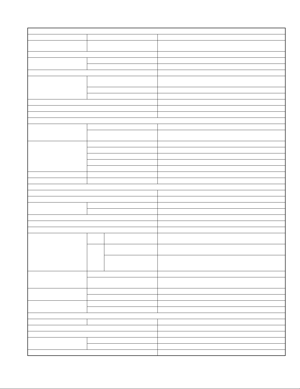
KD-ADV5380/KD-DV5300
AUDIO AMPLIFIER SECTION
Power Output 20 W RMS × 4 Channels at 4 Ω and - 1% THD+N
Signal to Noise Ratio 80 dBA (reference: 1 W into 4 Ω)
Load Impedance 4 Ω (4 Ω to 8 Ω allowance)
Tone Control Range Bass ±12 dB at 100 Hz
Treble ±12 dB at 10 kHz
Audio Output Level Digital (DIGITAL OUT: Optical) Signal wave length: 660 nm
Output level: -21 dBm to -15 dBm
Line-Out Level/Impedance 2.5 V/20 kΩ load (full scale)
Output Impedance 1 kΩ
Color system NTSC
Video Output (composite) 1 Vp-p/75 Ω
Other Terminal CD changer, AUX (auxiliary) input jack
TUNER SECTION
Frequency Range FM (with channel interval set to 100 kHz or 200 kHz) 87.5 MHz to 107.9 MHz
FM (with channel interval set to 50 kHz) 87.5 MHz to 108.0 MHz
AM (with channel interval set to 10 kHz) 530 kHz to 1 710 kHz
AM (with channel interval set to 9 kHz) 531 kHz to 1 602 kHz
FM Tuner Usable Sensitivity 11.3 dBf (1.0 µV/75 Ω)
50 dB Quieting Sensitivity 16.3 dBf (1.8 µV/75 Ω)
Alternate Channel Selectivity (400 kHz) 65 dB
Frequency Response 40 Hz to 15 000 Hz
Stereo Separation 35 dB
AM Tuner Sensitivity/Selectivity 20 µV/35 dB
DVD/CD PLAYER SECTION
Signal Detection System Non-contact optical pickup (semiconductor laser)
Number of Channels 2 channels (stereo)
Frequency Response DVD, fs=48 kHz/96 kHz 16 Hz to 22 000 Hz
CD, fs=44.1 kHz 16 Hz to 20 000 Hz
Dynamic Range 96 dB
Signal-to-Noise Ratio 98 dB
Wow and Flutter Less than measurable limit
DivX/MPEG Video Video Max. Resolution 720 × 480 pixels (30 fps)
Audio Bit Rate DivX: 32 kbps - 320 kbps
Sampling Frequency DivX: MPEG-1: 32 kHz, 44.1 kHz, 48 kHz
MP3 Bit Rate 32 kbps - 320 kbps
Sampling Frequency MPEG-1: 32 kHz, 44.1 kHz, 48 kHz
WMA Bit Rate 32 kbps - 320 kbps
Sampling Frequency 22.05 kHz, 32 kHz, 44.1 kHz, 48 kHz
WAV Quantization Bit Rate 16 bit
Sampling Frequency 44.1 kHz
GENERAL
Power Requirement Operating Voltage DC 14.4 V (11 V to 16 V allowance)
Grounding System Negative ground
Allowable Operating Temperature 0°C to +40°C (32°F to 104°F)
Dimensions (W × H × D) Installation Size (approx.) 182 mm × 52 mm × 158 mm (7-3/16" × 2-1/16" × 6-1/4")
Panel Size (approx.) 187 mm × 58 mm × 13 mm (7-3/8" × 2-5/16" × 9/16")
Mass (approx.) 1.6 kg (3.6 lbs) (excluding accessories)
720 × 576 pixels (25 fps)
MPEG Video: 32 kbps - 384 kbps
DivX: MPEG-2: 16 kHz, 22.05 kHz, 24 kHz
MPEG Video: 32 kHz, 44.1 kHz, 48 kHz
MPEG-2: 16 kHz, 22.05 kHz, 24 kHz
Design and specifications are subject to change without notice.
1-2 (No.MA308)
Page 3
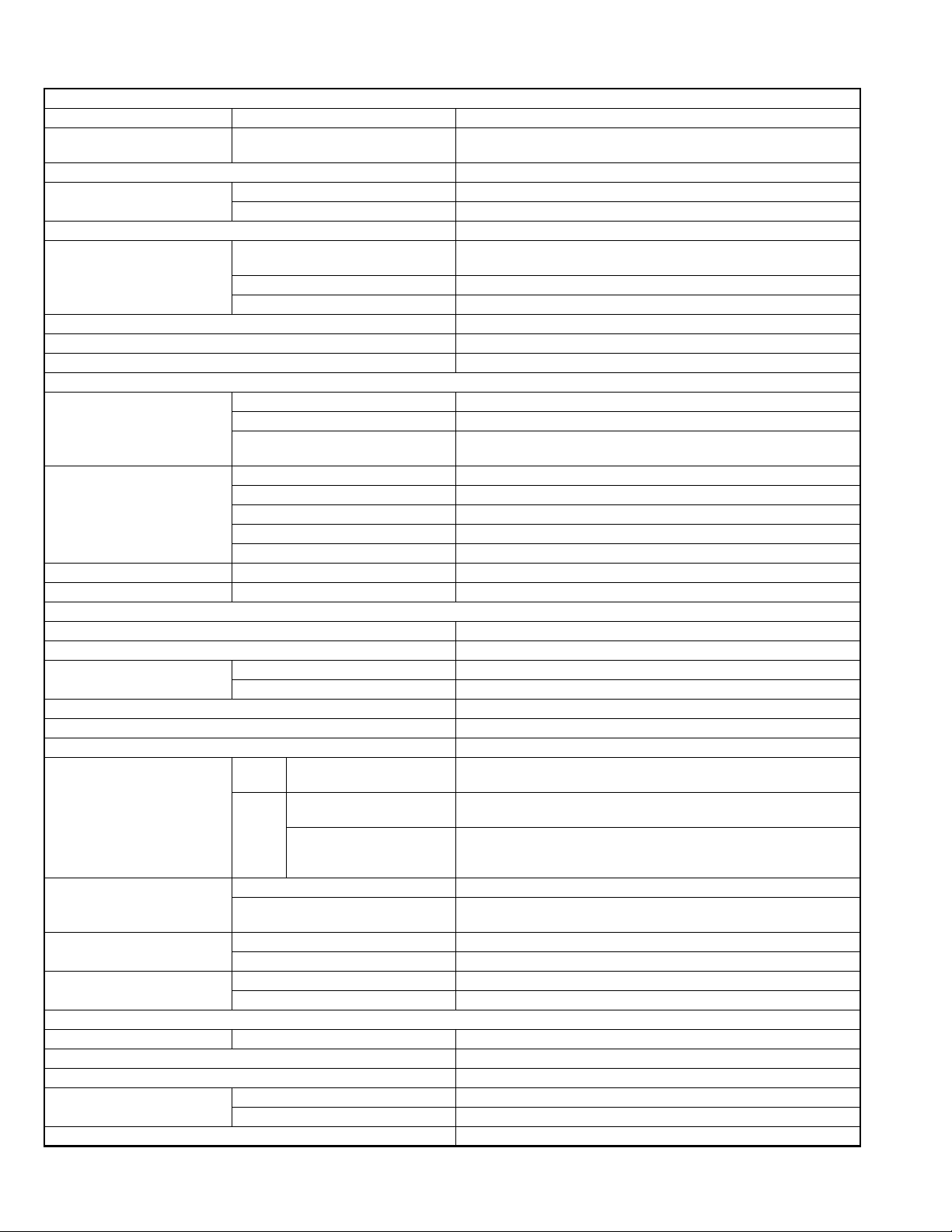
KD-DV5302/KD-DV5301
AUDIO AMPLIFIER SECTION
Maximum Power Output Front/Rear 50 W per channel
Continuous Power Output (RMS) Front/Rear 19 W per channel into 4 Ω, 40 Hz to 20 000 Hz at no more than 0.8% total
harmonic distortion
Load Impedance 4 Ω (4 Ω to 8 Ω allowance)
Tone Control Range Bass ±12 dB at 100 Hz
Treble ±12 dB at 10 kHz
Signal to Noise Ratio 70 dB
Audio Output Level Digital (DIGITAL OUT: Optical) Signal wave length: 660 nm
Output level: -21 dBm to -15 dBm
Line-Out Level/Impedance 2.5 V/20 kΩ load (full scale)
Output Impedance 1 kΩ
Color system PAL
Video Output (composite) 1 Vp-p/75 Ω
Other Terminal CD changer, LINE IN, Steering wheel remote input
TUNER SECTION
Frequency Range FM 87.5 MHz to 108.0 MHz
AM (MW) 522 kHz to 1 620 kHz
(LW) 144 kHz to 279 kHz
FM Tuner Usable Sensitivity 11.3 dBf (1.0 µV/75 Ω)
50 dB Quieting Sensitivity 16.3 dBf (1.8 µV/75 Ω)
Alternate Channel Selectivity (400 kHz) 65 dB
Frequency Response 40 Hz to 15 000 Hz
Stereo Separation 30 dB
MW Tuner Sensitivity/Selectivity 20 µV/35 dB
LW Tuner Sensitivity 50 µV
DVD/CD PLAYER SECTION
Signal Detection System Non-contact optical pickup (semiconductor laser)
Number of Channels 2 channels (stereo)
Frequency Response DVD, fs=48 kHz/96 kHz 16 Hz to 22 000 Hz
CD, fs=44.1 kHz 16 Hz to 20 000 Hz
Dynamic Range 96 dB
Signal-to-Noise Ratio 98 dB
Wow and Flutter Less than measurable limit
DivX/MPEG Video Video Max. Resolution 720 × 480 pixels (30 fps)
720 × 576 pixels (25 fps)
Audio Bit Rate DivX: 32 kbps - 320 kbps
MPEG Video: 32 kbps - 320 kbps
Sampling Frequency DivX: MPEG-1: 32 kHz, 44.1 kHz, 48 kHz
DivX: MPEG-2: 16 kHz, 22.05 kHz, 24 kHz
MPEG Video: 32 kHz, 44.1 kHz, 48 kHz
MP3 Bit Rate 32 kbps - 320 kbps
Sampling Frequency MPEG-1: 32 kHz, 44.1 kHz, 48 kHz
MPEG-2: 16 kHz, 22.05 kHz, 24 kHz
WMA Bit Rate 32 kbps - 320 kbps
Sampling Frequency 22.05 kHz, 32 kHz, 44.1 kHz, 48 kHz
WAV Quantization Bit Rate 16 bit
Sampling Frequency 44.1 kHz
GENERAL
Power Requirement Operating Voltage DC 14.4 V (11 V to 16 V allowance)
Grounding System Negative ground
Allowable Operating Temperature 0°C to +40°C
Dimensions (W × H × D) Installation Size (approx.) 182 mm × 52 mm × 158 mm
Panel Size (approx.) 187 mm × 58 mm × 13 mm
Mass (approx.) 1.6 kg (excluding accessories)
Design and specifications are subject to change without notice.
(No.MA308)1-3
Page 4

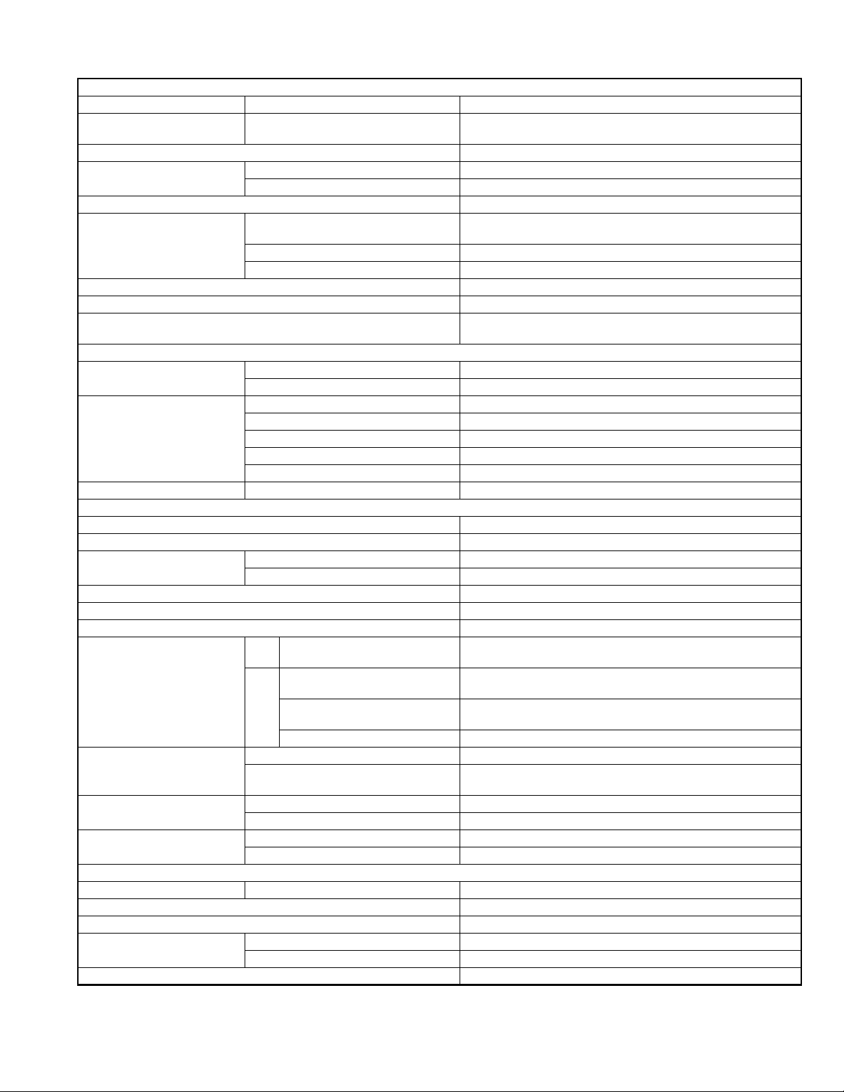
KD-DV5304/KD-DV4304
AUDIO AMPLIFIER SECTION
Maximum Power Output Front/Rear 50 W per channel
Continuous Power Output (RMS) Front/Rear 19 W per channel into 4 Ω, 40 Hz to 20 000 Hz at no more than 0.8%
total harmonic distortion
Load Impedance 4 Ω (4 Ω to 8 Ω allowance)
Tone Control Range Bass ±10 dB at 100 Hz
Treble ±10 dB at 10 kHz
Signal to Noise Ratio 70 dB
Audio Output Level Digital (DIGITAL OUT: Optical) Signal wave length: 660 nm
Output level: -21 dBm to -15 dBm
Line-Out Level/Impedance 2.5 V/20 kΩ load (full scale)
Output Impedance 1 kΩ
Color system PAL/NTSC
Video Output (composite) 1 Vp-p/75 Ω
Other Terminal KD-DV5304 : CD changer, LINE IN, AUX (auxiliary) input jack
KD-DV4304 : CD changer
TUNER SECTION
Frequency Range FM 87.5 MHz to 108.0 MHz
AM 531 kHz to 1 602 kHz
FM Tuner Usable Sensitivity 11.3 dBf (1.0 µV/75 Ω)
50 dB Quieting Sensitivity 16.3 dBf (1.8 µV/75 Ω)
Alternate Channel Selectivity (400 kHz) 65 dB
Frequency Response 40 Hz to 15 000 Hz
Stereo Separation 30 dB
AM Tuner Sensitivity/Selectivity 20 µV/35 dB
DVD/CD PLAYER SECTION
Signal Detection System Non-contact optical pickup (semiconductor laser)
Number of Channels 2 channels (stereo)
Frequency Response DVD, fs=48 kHz/96 kHz 16 Hz to 22 000 Hz
CD, fs=44.1 kHz 16 Hz to 20 000 Hz
Dynamic Range 96 dB
Signal-to-Noise Ratio 98 dB
Wow and Flutter Less than measurable limit
DivX/MPEG Video Video Max. Resolution 720 × 480 pixels (30 fps)
720 × 576 pixels (25 fps)
Audio Bit Rate DivX: 32 kbps - 320 kbps
MPEG Video: 32 kbps - 384 kbps
Sampling Frequency: DivX MPEG-1: 32 kHz, 44.1 kHz, 48 kHz
MPEG-2: 16 kHz, 22.05 kHz, 24 kHz
Sampling Frequency: MPEG Video 32 kHz, 44.1 kHz, 48 kHz
MP3 Bit Rate 32 kbps - 320 kbps
Sampling Frequency MPEG-1: 32 kHz, 44.1 kHz, 48 kHz
WMA Bit Rate 32 kbps - 320 kbps
Sampling Frequency 22.05 kHz, 32 kHz, 44.1 kHz, 48 kHz
WAV Quantization Bit Rate 16 bit
Sampling Frequency 44.1 kHz
GENERAL
Power Requirement Operating Voltage DC 14.4 V (11 V to 16 V allowance)
Grounding System Negative ground
Allowable Operating Temperature 0°C to +40°C
Dimensions (W × H × D) Installation Size (approx.) 182 mm × 52 mm × 158 mm
Panel Size (approx.) 187 mm × 58 mm × 13 mm
Mass (approx.) 1.6 kg (excluding accessories)
MPEG-2: 16 kHz, 22.05 kHz, 24 kHz
Design and specifications are subject to change without notice.
1-4 (No.MA308)
Page 5

KD-DV5306/KD-DV5305/KD-DV4306/KD-DV4305
AUDIO AMPLIFIER SECTION
Maximum Power Output Front/Rear 50 W per channel
Continuous Power Output
(RMS)
Load Impedance 4 Ω (4 Ω to 8 Ω allowance)
Tone Control Range Bass ±12 dB at 100 Hz
Signal to Noise Ratio 70 dB
Audio Output Level Digital (DIGITAL OUT: Optical) Signal wave length: 660 nm
Color system PAL/NTSC
Video Output (composite) 1 Vp-p/75 Ω
Other Terminal KD-DV5306/KD-DV5305 : CD changer, LINE IN, AUX (auxiliary) input jack
Frequency Range FM 87.5 MHz to 108.0 MHz
FM Tuner Usable Sensitivity 11.3 dBf (1.0 µV/75 Ω)
AM Tuner Sensitivity/Selectivity 20 µV/35 dB
Signal Detection System Non-contact optical pickup (semiconductor laser)
Number of Channels 2 channels (stereo)
Frequency Response DVD, fs=48 kHz/96 kHz 16 Hz to 22 000 Hz
Dynamic Range 96 dB
Signal-to-Noise Ratio 98 dB
Wow and Flutter Less than measurable limit
DivX/MPEG Video Video Max. Resolution 720 × 480 pixels (30 fps)
MP3 Bit Rate
WMA Bit Rate 32 kbps - 320 kbps
Power Requirement Operating Voltage DC 14.4 V (11 V to 16 V allowance)
Grounding System Negative ground
Allowable Operating Temperature 0°C to +40°C
Dimensions (W × H × D) Installation Size (approx.) 182 mm × 52 mm × 158 mm
Mass (approx.) 1.6 kg (excluding accessories)
Front/Rear 19 W per channel into 4 Ω, 40 Hz to 20 000 Hz at no more than 0.8% total har-
monic distortion
Treble ±12 dB at 10 kHz
Output level: -21 dBm to -15 dBm
Line-Out Level/Impedance 2.5 V/20 kΩ load (full scale)
Output Impedance 1 kΩ
KD-DV4306/KD-DV4305 : CD changer
TUNER SECTION
AM 531 kHz to 1 602 kHz
50 dB Quieting Sensitivity 16.3 dBf (1.8 µV/75 Ω)
Alternate Channel Selectivity (400 kHz) 65 dB
Frequency Response 40 Hz to 15 000 Hz
Stereo Separation 30 dB
DVD/CD PLAYER SECTION
CD, fs=44.1 kHz 16 Hz to 20 000 Hz
720 × 576 pixels (25 fps)
Audio Bit Rate DivX: 32 kbps - 320 kbps
MPEG Video: 32 kbps - 384 kbps
Sampling Frequency: DivX MPEG-1: 32 kHz, 44.1 kHz, 48 kHz
MPEG-2: 16 kHz, 22.05 kHz, 24 kHz
Sampling Frequency: MPEG Video 32 kHz, 44.1 kHz, 48 kHz
32 kbps - 320 kbps
Sampling Frequency
Sampling Frequency 22.05 kHz, 32 kHz, 44.1 kHz, 48 kHz
Quantization Bit Rate 16 bit
Sampling Frequency 44.1 kHz
Panel Size (approx.) 187 mm × 58 mm × 13 mm
MPEG-1: 32 kHz, 44.1 kHz, 48 kHz
MPEG-2: 16 kHz, 22.05 kHz, 24 kHz
GENERAL
Design and specifications are subject to change without notice.
(No.MA308)1-5
Page 6
KD-DV5308/KD-DV5307
AUDIO AMPLIFIER SECTION
Maximum Power Output Front/Rear 50 W per channel
Continuous Power Output (RMS) Front/Rear 19 W per channel into 4 Ω, 40 Hz to 20 000 Hz at no more than 0.8% total
harmonic distortion
Load Impedance 4 Ω (4 Ω to 8 Ω allowance)
Tone Control Range Bass ±12 dB at 100 Hz
Treble ±12 dB at 10 kHz
Signal to Noise Ratio 70 dB
Audio Output Level Digital (DIGITAL OUT: Optical) Signal wave length: 660 nm
Output level: -21 dBm to -15 dBm
Line-Out Level/Impedance 2.5 V/20 kΩ load (full scale)
Output Impedance 1 kΩ
Color system PAL
Video Output (composite) 1 Vp-p/75 Ω
Other Terminal CD changer
TUNER SECTION
Frequency Range FM1/FM2 87.5 MHz to 108.0 MHz
FM3 65.00 MHz to 74.00 MHz
AM (MW) 522 kHz to 1 620 kHz
FM Tuner Usable Sensitivity 11.3 dBf (1.0 µV/75 Ω)
50 dB Quieting Sensitivity 16.3 dBf (1.8 µV/75 Ω)
Alternate Channel Selectivity (400 kHz) 65 dB
Frequency Response 40 Hz to 15 000 Hz
Stereo Separation 30 dB
MW Tuner Sensitivity/Selectivity 20 µV/35 dB
LW Tuner Sensitivity 50 µV
DVD/CD PLAYER SECTION
Signal Detection System Non-contact optical pickup (semiconductor laser)
Number of Channels 2 channels (stereo)
Frequency Response DVD, fs=48 kHz/96 kHz 16 Hz to 22 000 Hz
CD, fs=44.1 kHz 16 Hz to 20 000 Hz
Dynamic Range 96 dB
Signal-to-Noise Ratio 98 dB
Wow and Flutter Less than measurable limit
DivX/MPEG Video Video Max. Resolution 720 × 480 pixels (30 fps)
Audio Bit Rate DivX: 32 kbps - 320 kbps
Sampling Frequency DivX: MPEG-1: 32 kHz, 44.1 kHz, 48 kHz
MP3 Bit Rate 32 kbps - 320 kbps
Sampling Frequency MPEG-1: 32 kHz, 44.1 kHz, 48 kHz
WMA Bit Rate 32 kbps - 320 kbps
Sampling Frequency 22.05 kHz, 32 kHz, 44.1 kHz, 48 kHz
WAV Quantization Bit Rate 16 bit
Sampling Frequency 44.1 kHz
Power Requirement Operating Voltage DC 14.4 V (11 V to 16 V allowance)
Grounding System Negative ground
Allowable Operating Temperature 0°C to +40°C
Dimensions (W × H × D) Installation Size (approx.) 182 mm × 52 mm × 158 mm
Panel Size (approx.) 187 mm × 58 mm × 13 mm
Mass (approx.) 1.6 kg (excluding accessories)
(LW) 144 kHz to 279 kHz
720 × 576 pixels (25 fps)
MPEG Video: 32 kbps - 320 kbps
DivX: MPEG-2: 16 kHz, 22.05 kHz, 24 kHz
MPEG Video: 32 kHz, 44.1 kHz, 48 kHz
MPEG-2: 16 kHz, 22.05 kHz, 24 kHz
GENERAL
Design and specifications are subject to change without notice.
1-6 (No.MA308)
Page 7
KD-DV5388/KD-DV4388
AUDIO AMPLIFIER SECTION
Maximum Power Output Front/Rear 50 W per channel
Continuous Power Output (RMS) Front/Rear 19 W per channel into 4 Ω, 40 Hz to 20 000 Hz at no more than 0.8%
total harmonic distortion
Load Impedance 4 Ω (4 Ω to 8 Ω allowance)
Tone Control Range Bass ±12 dB at 100 Hz
Treble ±12 dB at 10 kHz
Signal to Noise Ratio 70 dB
Audio Output Level Digital (DIGITAL OUT: Optical) Signal wave length: 660 nm
Output level: -21 dBm to -15 dBm
Line-Out Level/Impedance 2.5 V/20 kΩ load (full scale)
Output Impedance 1 kΩ
Color system PAL/NTSC
Video Output (composite) 1 Vp-p/75 Ω
Other Terminal KD-DV5388 : CD changer,LINE IN, AUX (auxiliary) input jack
KD-DV4388 : CD changer
TUNER SECTION
Frequency Range FM 87.5 MHz to 108.0 MHz
AM 531 kHz to 1 602 kHz
FM Tuner Usable Sensitivity 11.3 dBf (1.0 µV/75 Ω)
50 dB Quieting Sensitivity 16.3 dBf (1.8 µV/75 Ω)
Alternate Channel Selectivity (400 kHz) 65 dB
Frequency Response 40 Hz to 15 000 Hz
Stereo Separation 30 dB
MW Tuner Sensitivity/Selectivity 20 µV/35 dB
DVD/CD PLAYER SECTION
Signal Detection System Non-contact optical pickup (semiconductor laser)
Number of Channels 2 channels (stereo)
Frequency Response DVD, fs=48 kHz/96 kHz 16 Hz to 22 000 Hz
CD, fs=44.1 kHz 16 Hz to 20 000 Hz
Dynamic Range 96 dB
Signal-to-Noise Ratio 98 dB
Wow and Flutter Less than measurable limit
DivX/MPEG Video Video Max. Resolution 720 × 480 pixels (30 fps)
720 × 576 pixels (25 fps)
Audio Bit Rate DivX: 32 kbps - 320 kbps
MPEG Video: 32 kbps - 384 kbps
Sampling Frequency : DivX MPEG-1: 32 kHz, 44.1 kHz, 48 kHz
MPEG-2: 16 kHz, 22.05 kHz, 24 kHz
Sampling Frequency : MPEG Video 32 kHz, 44.1 kHz, 48 kHz
MP3 Bit Rate 32 kbps - 320 kbps
Sampling Frequency MPEG-1: 32 kHz, 44.1 kHz, 48 kHz
WMA Bit Rate 32 kbps - 320 kbps
Sampling Frequency 22.05 kHz, 32 kHz, 44.1 kHz, 48 kHz
WAV Quantization Bit Rate 16 bit
Sampling Frequency 44.1 kHz
GENERAL
Power Requirement Operating Voltage DC 14.4 V (11 V to 16 V allowance)
Grounding System Negative ground
Allowable Operating Temperature 0°C to +40°C
Dimensions (W × H × D) Installation Size (approx.) 182 mm × 52 mm × 158 mm
Panel Size (approx.) 187 mm × 58 mm × 13 mm
Mass (approx.) 1.6 kg (excluding accessories)
MPEG-2: 16 kHz, 22.05 kHz, 24 kHz
Design and specifications are subject to change without notice.
(No.MA308)1-7
Page 8

KD-DVH426
AUDIO AMPLIFIER SECTION
Maximum Power Output Front/Rear 50 W per channel
Continuous Power Output (RMS) Front/Rear 19 W per channel into 4 Ω, 40 Hz to 20 000 Hz at no more than 0.8% total
harmonic distortion
Load Impedance 4 Ω (4 Ω to 8 Ω allowance)
Tone Control Range Bass/Treble ±10 dB at 100 Hz/±10 dB at 10 kHz
Frequency Response 40 Hz to 20 000 Hz
Signal-to-Noise Ratio 70 dB
Audio Output Level Digital (DIGITAL OUT: Optical) Signal wave length: 660 nm
Output level: -21 dBm to -15 dBm
Line-Out Level/Impedance 2.0 V/20 kΩ load (full scale)
Output Impedance 1 kΩ
Color System PAL/NTSC
Video Output (composite) 1 Vp-p/75 Ω
Other Terminal CD changer
TUNER SECTION
Frequency Range FM 87.5 MHz to 108.0 MHz
AM 531 kHz to 1 602 kHz
FM Tuner Usable Sensitivity 11.3 dBf (1.0 µV/75 Ω)
50 dB Quieting Sensitivity 16.3 dBf (1.8 µV/75 Ω)
Alternate Channel Selectivity (400 kHz) 65 dB
Frequency Response 40 Hz to 15 000 Hz
Stereo Separation 30 dB
AM Tuner Sensitivity/Selectivity 20 µV/35 dB
DVD/CD PLAYER SECTION
Signal Detection System Non-contact optical pickup (semiconductor laser)
Number of Channels 2 channels (stereo)
Frequency Response DVD, fs=48 kHz 16 Hz to 22 000 Hz
DVD, fs=96 kHz 16 Hz to 44 000 Hz
VCD/CD/MP3/WMA 16 Hz to 20 000 Hz
Dynamic Range 96 dB
Signal-to-Noise Ratio 98 dB
Wow and Flutter Less than measurable limit
MP3 Bit Rate 32 kbps - 320 kbps
Sampling Frequency 48 kHz, 44.1 kHz, 32 kHz
WMA Bit Rate 32 kbps - 192 kbps
Sampling Frequency MPEG-1: 48 kHz, 44.1 kHz, 33 kHz
Power Requirement Operating Voltage DC 14.4 V (11 V to 16 V allowance)
Grounding System Negative ground
Allowable Operating Temperature 0°C to +40°C
Dimensions (W × H × D) Installation Size (approx.) 182 mm × 52 mm × 158 mm
Panel Size (approx.) 188 mm × 58 mm × 11 mm
Mass (approx.) 1.6 kg (excluding accessories)
MPEG-2: 24 kHz, 22.05 kHz, 16 kHz
GENERAL
Design and specifications are subject to change without notice.
1-8 (No.MA308)
Page 9
1.1 Safety Precautions
SECTION 1
PRECAUTION
!
!
Burrs formed during molding may be left over on some parts of the chassis. Therefore,
pay attention to such burrs in the case of preforming repair of this system.
Please use enough caution not to see the beam directly or touch it in case of an
adjustment or operation check.
(No.MA308)1-9
Page 10
1.2 Preventing static electricity
Electrostatic discharge (ESD), which occurs when static electricity stored in the body, fabric, etc. is discharged, can destroy the laser
diode in the traverse unit (optical pickup). Take care to prevent this when performing repairs.
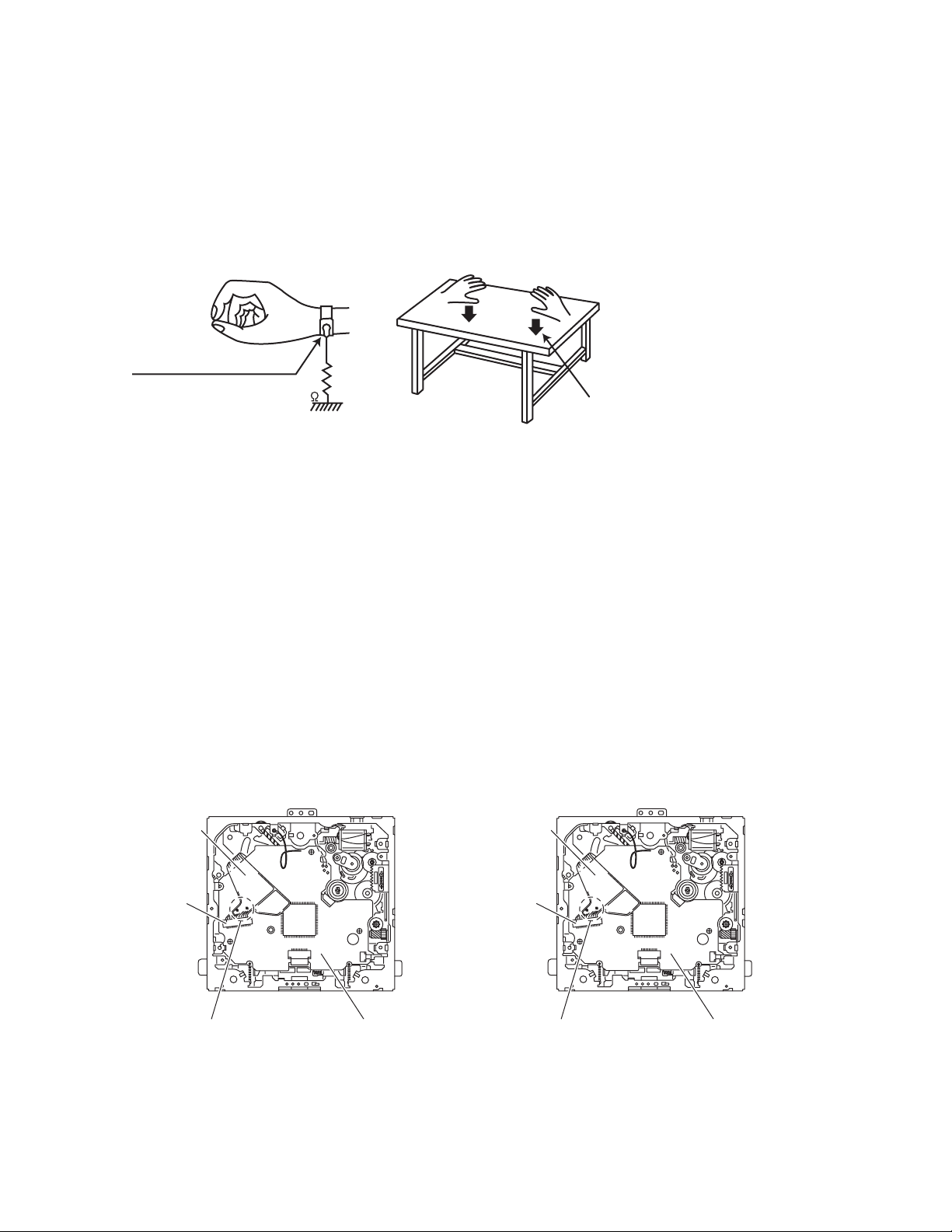
1.2.1 Grounding to prevent damage by static electricity
Static electricity in the work area can destroy the optical pickup (laser diode) in devices such as laser products.
Be careful to use proper grounding in the area where repairs are being performed.
(1) Ground the workbench
Ground the workbench by laying conductive material (such as a conductive sheet) or an iron plate over it before placing the
traverse unit (optical pickup) on it.
(2) Ground yourself
Use an anti-static wrist strap to release any static electricity built up in your body.
(caption)
Anti-static wrist strap
1M
Conductive material
(conductive sheet) or iron plate
(3) Handling the optical pickup
• In order to maintain quality during transport and before installation, both sides of the laser diode on the replacement optical
pickup are shorted. After replacement, return the shorted parts to their original condition.
(Refer to the text.)
• Do not use a tester to check the condition of the laser diode in the optical pickup. The tester's internal power source can easily
destroy the laser diode.
1.3 Handling the traverse unit (optical pickup)
(1) Do not subject the traverse unit (optical pickup) to strong shocks, as it is a sensitive, complex unit.
(2) Cut off the shorted part of the flexible cable using nippers, etc. after replacing the optical pickup. For specific details, refer to the
replacement procedure in the text. Remove the anti-static pin when replacing the traverse unit. Be careful not to take too long a
time when attaching it to the connector.
(3) Handle the flexible cable carefully as it may break when subjected to strong force.
(4) It is not possible to adjust the semi-fixed resistor that adjusts the laser power. Do not turn it.
1.4 Attention when traverse unit is decomposed
*Please refer to "Disassembly method" in the text for the pickup unit.
• Apply solder to the short land before the card wire is disconnected from the connector on the pickup unit.
(If the card wire is disconnected without applying solder, the pickup may be destroyed by static electricity.)
• In the assembly, be sure to remove solder from the short land after connecting the card wire.
[except KD-DVH426] [for KD-DVH426]
Flexible wire
Flexible wire
1-10 (No.MA308)
CN101
Short-circuit points
Mechanism control board
CN101
Short-circuit points
Mechanism control board
Page 11
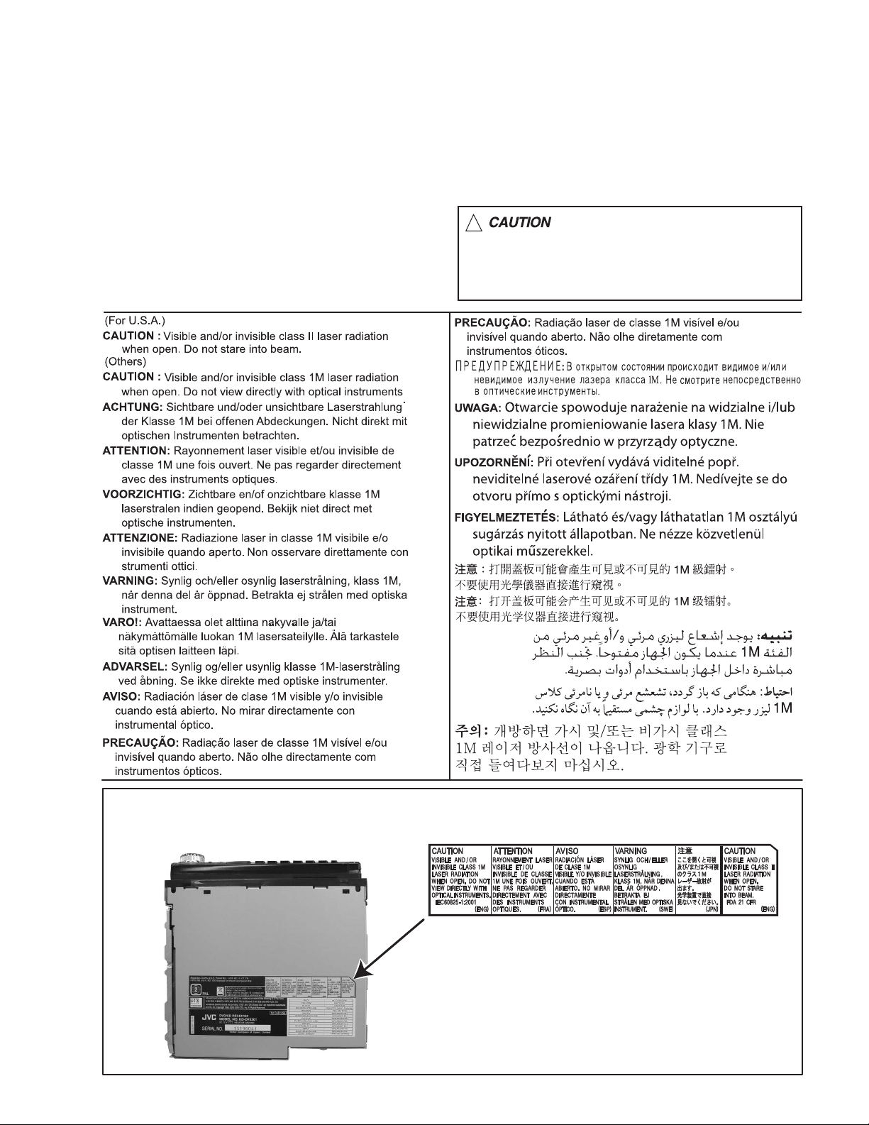
1.5 Important for laser products
1.CLASS 1 LASER PRODUCT
2.CAUTION :
(For U.S.A.) Visible and/or invisible class II laser radiation
when open. Do not stare into beam.
(Others) Visible and/or invisible class 1M laser radiation
when open. Do not view directly with optical instruments.
3.CAUTION : Visible and/or invisible laser radiation when
open and inter lock failed or defeated. Avoid direct
exposure to beam.
4.CAUTION : This laser product uses visible and/or invisible
laser radiation and is equipped with safety switches which
prevent emission of radiation when the drawer is open and
the safety interlocks have failed or are defeated. It is
dangerous to defeat the safety switches.
5.CAUTION : If safety switches malfunction, the laser is able
to function.
6.CAUTION : Use of controls, adjustments or performance of
procedures other than those specified here in may result in
hazardous radiation exposure.
!
Please use enough caution not to
see the beam directly or touch it
in case of an adjustment or operation
check.
REPRODUCTION AND POSITION OF LABELS and PRINT
WARNING LABEL and PRINT
(No.MA308)1-11
Page 12

SECTION 2
SPECIFIC SERVICE INSTRUCTIONS
This service manual does not describe SPECIFIC SERVICE INSTRUCTIONS.
1-12 (No.MA308)
Page 13
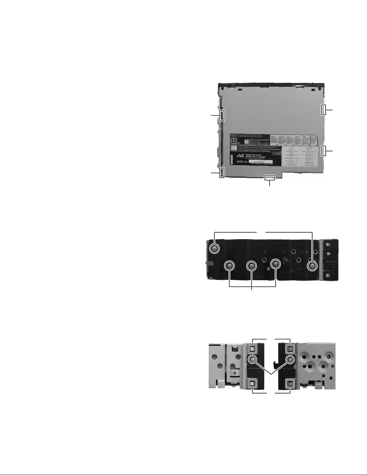
3.1 Main body
3.1.1 Removing the Bottom chassis
(See Fig.1)
(1) Disengage the five hooks a engaged bottom chassis.
SECTION 3
DISASSEMBLY
3.1.2 Removing the Heat sink
(See Fig.2)
(1) Remove the two screws A and three screws B attaching
the Heat sink.
a
a
a
a
a
Fig.1
A
3.1.3 Removing the Front chassis assembly
(See Fig.3)
(1) From the both side of Front chassis, remove the two
screws C attaching the Front chassis.
(2) Disengage the both side of four hooks b engaged Front
chassis.
B
Fig.2
b
C
b
Fig.3
(No.MA308)1-13
Page 14
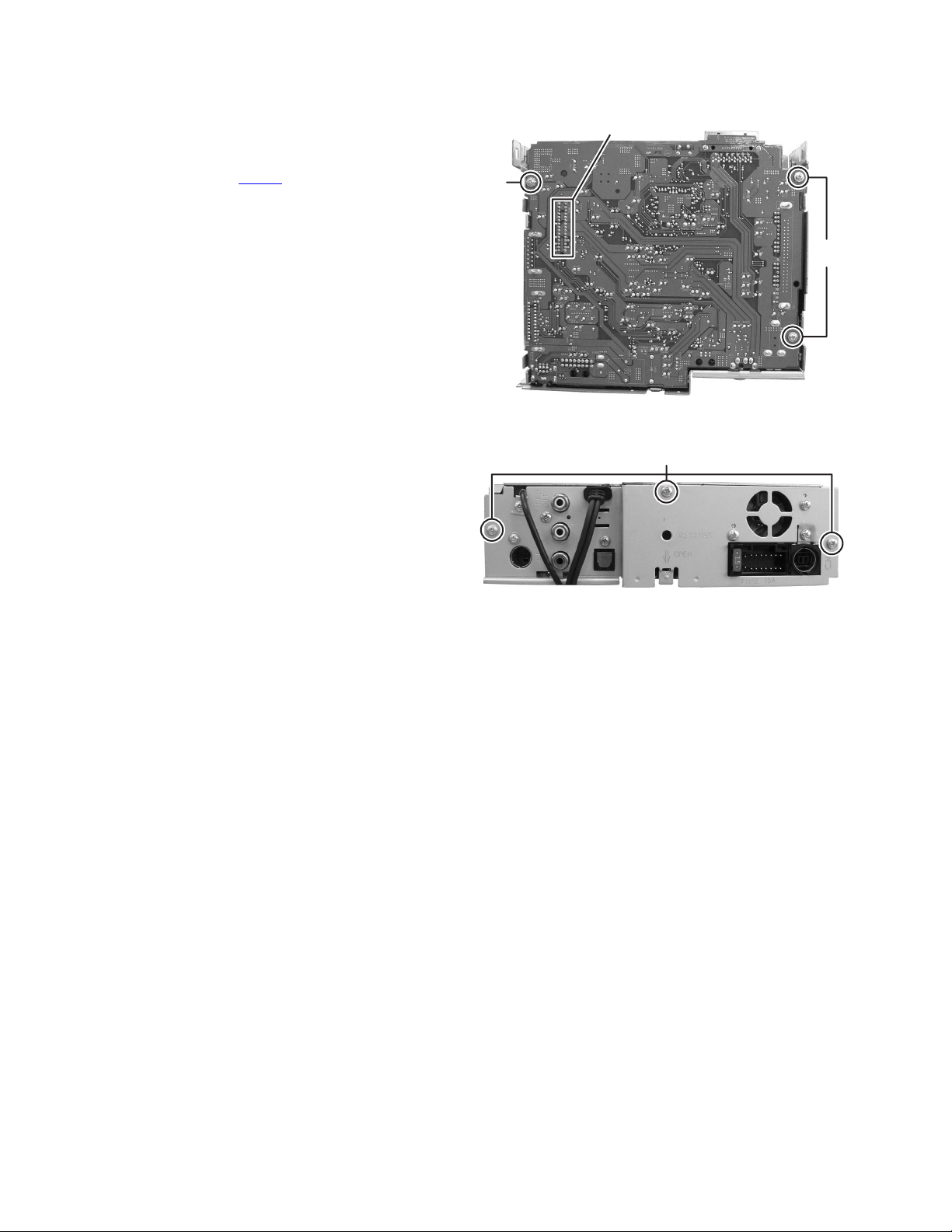
3.1.4 Removing the Main board assembly
(See Fig.4 and 5)
(1) Remove the three screws D attaching the Main board as-
sembly. (See Fig.4)
(2) Remove the three screws E attaching Rear bracket. (See
Fig.5)
(3) Disconnect the connector CN961
anism assembly. (See Fig.4)
connected to DVD mech-
CN961
D
D
Fig.4
E
Fig.5
1-14 (No.MA308)
Page 15

3.1.5 Removing the DVD mechanism assembly
(See Fig.6 and 7)
(1) Remove the three screws F attaching the DVD mechanism
assembly. (See Fig.6)
(2) Remove the two screws G attaching the DVD bracket. (See
Fig.7)
F
F
Fig.6
3.1.6 Removing the Switch board assembly
(See Fig.8)
(1) Remove the Volume knob from Front panel assembly.
(2) Remove the five screws H attaching the Back cover.
(3) Disengage the fourteen hooks c engaged Back cover.
G
G
Fig.7
HH
cccc
cc
HHH
cc
Fig.8
(No.MA308)1-15
Page 16

3.2 DVD mechanism assembly (except KD-DVH426)
3.2.1 Removing the mechanism control board
(See Fig.1)
Caution:
Before disconnecting the flexible wire extending from the DVD
pickup, solder the short-circuit point on the flexible wire using
a grounding soldering iron. If you do not follow this instruction,
the DVD pickup may be damaged.
(1) Turn over the body, and solder the short-circuit points on
the flexible wire extending from the DVD pickup.
(2) Disconnect the flexible wire from connector CN101
mechanism control board.
(3) Disconnect the card wire from connector CN201
mechanism control board.
(4) Disconnect the flexible wire from connector CN202
mechanism control board.
(5) Unsolder two soldered points a on the mechanism control
board and remove the wire extending from the feed motor.
(6) Remove the screw A attaching the lug wire.
(7) Remove the two screws B and screw C attaching the
mechanism control board.
Caution:
• As the flexible wire to be connected to CN101
attach it to the mechanism control board using a double
tape.
• After reassembling, unsolder the short-circuit points.
on the
on the
on the
, make sure to
Flexible wire
Double tape
CN101
B
Short-circuit points
A
Lug wire
B
CN201
Feed motor
a
C
CN202
Mechanism control board
Fig.1
1-16 (No.MA308)
Page 17

3.2.2 Removing the top cover
(See Fig.2)
(1) Remove the two screws D attaching the top cover on the
back of the body.
(2) Remove the top cover upward.
Reference:
When reassembling, set part b of the top cover under the
bending part c of the chassis frame.
3.2.3 Removing the mechanism section
(See Fig.2 to 4)
• Remove the top cover.
(1) From the bottom of the body, remove the screw E attaching
the lug wire. (See Fig.2.)
(2) Remove the two screws F attaching the right and left stop-
pers on the front side. (See Fig.2.)
(3) Remove the two floating springs on the bottom of the body.
(See Fig.3.)
(4) Move the mechanism section upward and remove from the
chassis frame.
The three damper springs come off from the dampers.
(See Fig.4.)
Caution:
• When reassembling, reattach the damper spring to the
damper respectively and insert the three shafts on the bottom of the mechanism to the dampers.
• Before inserting the shaft to the dampers, apply IPA to the
hole of damper.
Floating spring
Fig.3
Mechanism section
Stopper
F
Top cover
Stopper
F
D
D
b
c
E
Lug wire
Damper SP.(F)
(Silver)
Damper (F)
(Black)
Damper SP.(F)
(Silver)
Damper (F)
(Black)
Fig.4
Damper SP.(R)
(Red)
Damper (R)
(Purple)
Chassis frame
Fig.2
(No.MA308)1-17
Page 18

3.2.4 Removing the clamper unit
(See Fig.5 to 7)
• Remove the top cover and the mechanism section.
(1) Remove the clamper2 spring on the bottom of the mecha-
nism section. (See Figs.5.and 6.)
(2) Release the part d of the clamper spring from the bending
part of the chassis base assembly. (See Fig.7.)
(3) Move the clamper unit in the direction of the arrow and turn.
Release the two joints e and f, then remove the clamper
unit upward. (See Fig.6.)
3.2.5 Reattaching the clamper unit
(See Fig.5 to 9)
(1) Attach the clamper spring to the clamper unit. (See Fig.8.)
(2) Move the clamper unit to set the side joints e and f to each
boss of the chassis base assembly. Make sure that part g
is inserted to the notch of the chassis base assembly. (See
Figs.5 and 9.)
(3) Move the part d of the clamper spring to the outside of the
bending part of the chassis base assembly. (See Fig.7.)
(4) Attach the clamper2 spring to the chassis base assembly.
(See Figs.5 and 6.)
Caution:
When reattaching, temporarily hook the end of the clamper
spring as shown in the figure to make the work easy. (See
Fig.8.)
Clamper unit
Clamper2 spring
Chassis base assembly
Fig.6
Clamper spring
Clamper spring
f
Clamper2 spring
Chassis base assembly
g
d
Chassis base assembly
Fig.7
e
Fig.5
1-18 (No.MA308)
Page 19

Clamper unit
Clamper unit
Clamper spring
Fig.8
Fig.9
g
Notch
(No.MA308)1-19
Page 20

3.2.6 Removing the front unit
(See Fig.10 to 12)
• Remove the top cover and the mechanism section.
(1) Disconnect the flexible wire from connector CN202 on the
mechanism control board at the bottom of the body. (See
Fig.10.)
(2) Remove the screw G attaching the front unit on the top of
the body. (See Fig.11.)
(3) Move the front unit toward the front to release joint h, and
release two joints i and j on the right side of the chassis
base assembly. Then remove the front unit upward. (See
Figs.11 and 12.)
(4) Remove the two screws H attaching the switch board. (See
Fig.12.)
Reference:
You can remove the switch board only without removing the
front unit.
Caution:
When reassembling, attach the flexible wire extending from
the switch board using the double tape. (See Figs.10 and 12.)
Mechanism control board
G
Front unit
h
Fig.11
CN202
Double tape
Fig.10
Flexible wire
Double tape
j
i
H
Switch board
Front unit
G
1-20 (No.MA308)
h
Fig.12
Page 21

3.2.7 Removing the loading arm assembly
(See Fig.13 , 14)
• Remove the top cover, the mechanism section and the front
unit.
(1) From the top of the body, move the loading arm assembly
from the front side upward, and release the bosses from
the right and left joints k and m of the chassis base assembly.
(2) Release the boss from notch n of the connect arm on the
right side of the body, and release the boss from notch p of
the slide cam assembly on the left side.
m
Loading arm assembly
Side cam
assembly
p
m
k
Fig.13
Loading arm assembly
k
n
n
Connect arm
Fig.14
(No.MA308)1-21
Page 22
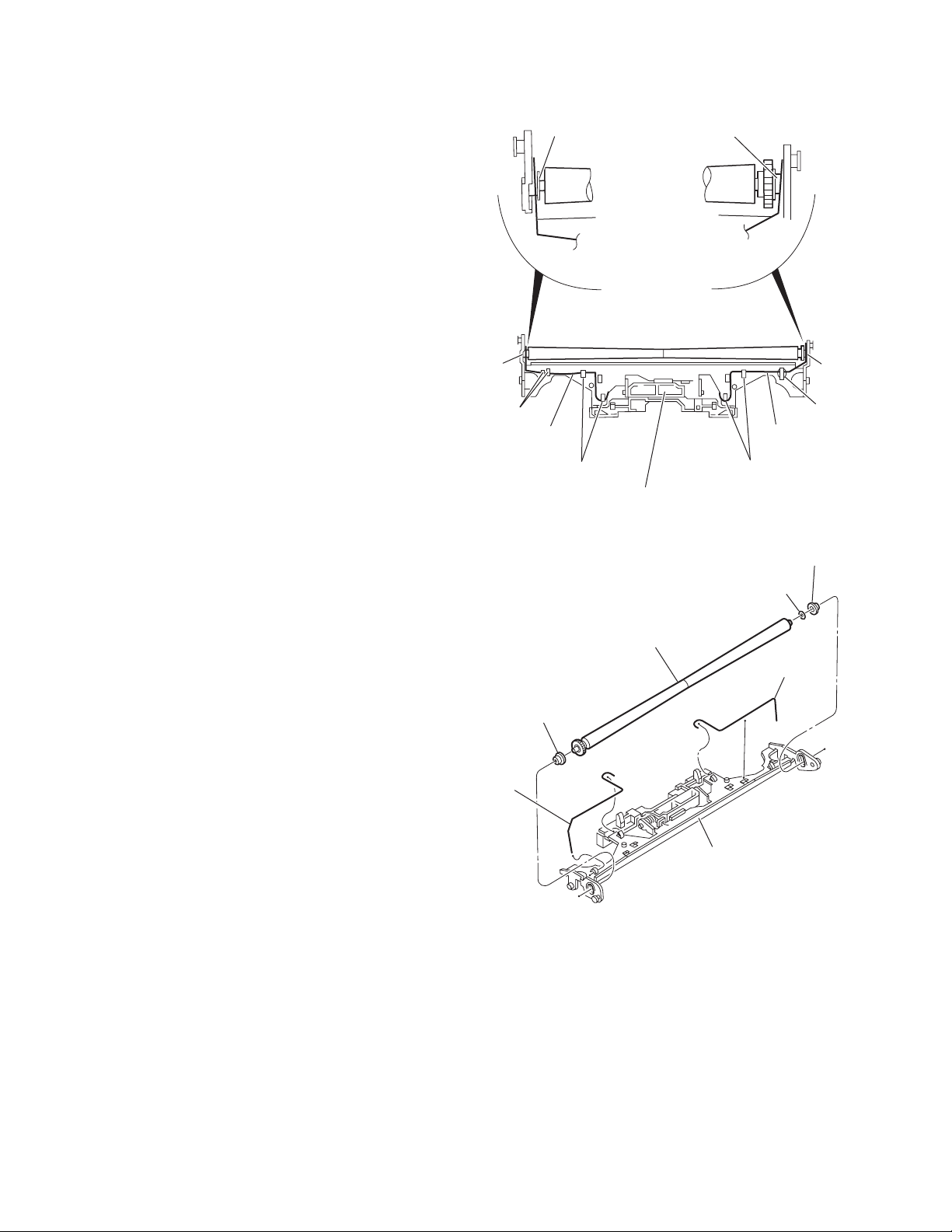
3.2.8 Removing the rod (L)(R)/roller assembly
(See Fig.15 and 16)
• Remove the top cover, the mechanism section, the front unit
and the loading arm assembly.
(1) Release the rod (L) and (R) from the joints q at the bottom
of the loading arm assembly (See Fig.15.)
(2) Remove the roller assembly from the loading arm assem-
bly. (See Fig.16.)
(3) Remove the two collars and washer from the roller assem-
bly. (See Fig.16.)
Caution:
After attaching the loading arm assembly to the roller assembly, attach the rod (L) and (R). Attach the rods to the right and
left collars of the roller. (See Fig.15.)
When reattaching the rod (L) and (R) to the loading arm assembly, engage each joint as shown in Fig.15. As joints q of
the rod (L), let the rod through q before reattaching it.
Collar
Collar
Rod(R) Rod(L)
q
q
q
Collar
Rod(L)
Rod(R)
q
Loading arm assembly
Fig.15
Roller assembly
Loading arm assembly
q
Rod(L)
q
Collar
Washer
Rod(R)
1-22 (No.MA308)
Fig.16
Page 23

3.2.9 Removing the DVD pickup assembly
(See Fig.17 to 19)
• Remove the mechanism control board.
(1) From the bottom of the body, turn the feed gear in the di-
rection of the arrow to move the DVD pickup outwards.
(See Fig.17.)
(2) Remove the screw J attaching the thrust spring. (See
Fig.17.)
(3) Remove the DVD pickup assembly upward on the L.S.gear
side and release from sub shaft at joint r. Move the lead
screw of the DVD pickup assembly in the direction of the
arrow to release from joint s. (See Fig.18.)
Caution:
• When releasing the lead screw at joint s, the L.S.collar
comes off at the end of the lead screw. When reassembling, reattach the L.S.collar to the lead screw and
engage joint s. (See Fig.18.)
• When reattaching the L.S.collar, reattach it to the point
s of the lead screw, and to the rod (M). Make sure that
the L.S.collar is set on the rod (M) spring. (See Fig.18.)
(4) Remove the screw K attaching the rack spring/ rack plate
on the DVD pickup. (See Fig.19.)
(5) Pull out the lead screw. (See Fig.19.)
Caution:
Perform adjustment after replacing the pickup.
DVD Pickup assembly
DVD Pickup assembly
Feed gear
J
Thrust spring
Fig.17
s
L.S.collar
Rod(M)
Lead screw
Sub shaft
L.S.collar
r
L.S.gear
Fig.18
K
Rack spring
Lead screw
Rack plate
DVD Pickup
Fig.19
(No.MA308)1-23
Page 24

3.2.10 Removing the spindle motor
r
(See Fig.20)
• Remove the mechanism control board.
Remove the two screws L attaching the spindle motor on the
bottom of the body.
Caution:
Perform adjustment when reattaching the spindle motor.
3.2.11 Removing the feed motor assembly
(See Fig.21 and 22)
• Remove the mechanism control board.
(1) Remove the feed TRI. spring on the bottom of the body.
(See Fig.21.)
(2) Remove the two screws M attaching the feed motor as-
sembly. (See Fig.21.)
(3) Remove the slit washer from the motor H. assembly and
pull out the worm wheel. (See Fig.22.)
Remove the two screws N attaching the feed motor. (See
Fig.22.)
Spindle motor
Feed TRI. spring
L
Fig.20
M
Feed motor assembly
1-24 (No.MA308)
Fig.21
Slit washer
Worm wheel
Feed moto
N
Motor H. assembly
Fig.22
Page 25

3.3 DVD mechanism assembly (for KD-DVH426)
3.3.1 Removing the mechanism control board
(See Fig.1)
Caution:
Before disconnecting the flexible wire extending from the DVD
pickup, solder the short-circuit point on the flexible wire using
a grounding soldering iron. If you do not follow this instruction,
the DVD pickup may be damaged.
(1) Turn over the body, and solder the short-circuit points on
the flexible wire extending from the DVD pickup.
(2) Disconnect the flexible wire from connector CN101
mechanism control board.
(3) Disconnect the card wire from connector CN201
mechanism control board.
(4) Disconnect the flexible wire from connector CN202
mechanism control board.
(5) Unsolder two soldered points a on the mechanism control
board and remove the wire extending from the feed motor.
(6) Remove the screw A attaching the lug wire.
(7) Remove the two screws B and screw C attaching the
mechanism control board.
Caution:
• As the flexible wire to be connected to CN101
attach it to the mechanism control board using a double
tape.
• After reassembling, unsolder the short-circuit points.
on the
on the
on the
, make sure to
Flexible wire
Double tape
CN101
B
Short-circuit points
A
Lug wire
B
CN201
Feed motor
a
C
CN202
Mechanism control board
Fig.1
(No.MA308)1-25
Page 26

3.3.2 Removing the top cover
(See Fig.2)
(1) Remove the two screws D attaching the top cover on the
back of the body.
(2) Remove the top cover upward.
Reference:
When reassembling, set part b of the top cover under the
bending part c of the chassis frame.
3.3.3 Removing the mechanism section
(See Fig.2 to 4)
• Remove the top cover.
(1) From the bottom of the body, remove the screw E attaching
the lug wire. (See Fig.2.)
(2) Remove the two screws F attaching the right and left stop-
pers on the front side. (See Fig.2.)
(3) Remove the two floating springs on the bottom of the body.
(See Fig.3.)
(4) Move the mechanism section upward and remove from the
chassis frame.
The three damper springs come off from the dampers.
(See Fig.4.)
Caution:
• When reassembling, reattach the damper spring to the
damper respectively and insert the three shafts on the bottom of the mechanism to the dampers.
• Before inserting the shaft to the dampers, apply IPA to the
hole of damper.
Floating spring
Fig.3
Mechanism section
Stopper
F
Top cover
Stopper
F
D
D
b
c
E
Lug wire
Damper SP.(F)
(Silver)
Damper (F)
(Black)
Damper SP.(F)
(Silver)
Damper (F)
(Black)
Fig.4
Damper SP.(R)
(Red)
Damper (R)
(Purple)
Chassis frame
1-26 (No.MA308)
Fig.2
Page 27

3.3.4 Removing the clamper unit
(See Fig.5 to 7)
• Remove the top cover and the mechanism section.
(1) Remove the clamper2 spring on the bottom of the mecha-
nism section. (See Figs.5.and 6.)
(2) Release the part d of the clamper spring from the bending
part of the chassis base assembly. (See Fig.7.)
(3) Move the clamper unit in the direction of the arrow and turn.
Release the two joints e and f, then remove the clamper
unit upward. (See Fig.6.)
3.3.5 Reattaching the clamper unit
(See Fig.5 to 9)
(1) Attach the clamper spring to the clamper unit. (See Fig.8.)
(2) Move the clamper unit to set the side joints e and f to each
boss of the chassis base assembly. Make sure that part g
is inserted to the notch of the chassis base assembly. (See
Figs.5 and 9.)
(3) Move the part d of the clamper spring to the outside of the
bending part of the chassis base assembly. (See Fig.7.)
(4) Attach the clamper2 spring to the chassis base assembly.
(See Figs.5 and 6.)
Caution:
When reattaching, temporarily hook the end of the clamper
spring as shown in the figure to make the work easy. (See
Fig.8.)
Clamper unit
Clamper2 spring
Chassis base assembly
Fig.6
Clamper spring
Clamper spring
f
Clamper2 spring
Chassis base assembly
g
d
Chassis base assembly
Fig.7
e
Fig.5
(No.MA308)1-27
Page 28

Clamper unit
Clamper unit
Clamper spring
Fig.8
1-28 (No.MA308)
Fig.9
g
Notch
Page 29

3.3.6 Removing the front unit
(See Fig.10 to 12)
• Remove the top cover and the mechanism section.
(1) Disconnect the flexible wire from connector CN202
mechanism control board at the bottom of the body. (See
Fig.10.)
(2) Remove the screw G attaching the front unit on the top of
the body. (See Fig.11.)
(3) Move the front unit toward the front to release joint h, and
release two joints i and j on the right side of the chassis
base assembly. Then remove the front unit upward. (See
Figs.11 and 12.)
(4) Remove the two screws H attaching the switch board. (See
Fig.12.)
Reference:
You can remove the switch board only without removing the
front unit.
Caution:
When reassembling, attach the flexible wire extending from
the switch board using the double tape. (See Figs.10 and 12.)
Mechanism control board
on the
G
Front unit
h
Fig.11
CN202
Double tape
Fig.10
Flexible wire
Double tape
j
i
H
Switch board
Front unit
G
Fig.12
h
(No.MA308)1-29
Page 30

3.3.7 Removing the loading arm assembly
(See Fig.13 , 14)
• Remove the top cover, the mechanism section and the front
unit.
(1) From the top of the body, move the loading arm assembly
from the front side upward, and release the bosses from
the right and left joints k and m of the chassis base assembly.
(2) Release the boss from notch n of the connect arm on the
right side of the body, and release the boss from notch p of
the slide cam assembly on the left side.
m
Loading arm assembly
Side cam
assembly
p
m
k
Fig.13
Loading arm assembly
k
n
n
Connect arm
1-30 (No.MA308)
Fig.14
Page 31

3.3.8 Removing the rod (L)(R)/roller assembly
(See Fig.15 and 16)
• Remove the top cover, the mechanism section, the front unit
and the loading arm assembly.
(1) Release the rod (L) and (R) from the joints q at the bottom
of the loading arm assembly (See Fig.15.)
(2) Remove the roller assembly from the loading arm assem-
bly. (See Fig.16.)
(3) Remove the two collars and washer from the roller assem-
bly. (See Fig.16.)
Caution:
After attaching the loading arm assembly to the roller assembly, attach the rod (L) and (R). Attach the rods to the right and
left collars of the roller. (See Fig.15.)
When reattaching the rod (L) and (R) to the loading arm assembly, engage each joint as shown in Fig.15. As joints q of
the rod (L), let the rod through q before reattaching it.
Collar
Collar
Rod(R) Rod(L)
q
q
q
Collar
Rod(L)
Rod(R)
q
Loading arm assembly
Fig.15
Roller assembly
Loading arm assembly
q
Rod(L)
q
Collar
Washer
Rod(R)
Fig.16
(No.MA308)1-31
Page 32

3.3.9 Removing the DVD pickup assembly
(See Fig.17 to 19)
• Remove the mechanism control board.
(1) From the bottom of the body, turn the feed gear in the di-
rection of the arrow to move the DVD pickup outwards.
(See Fig.17.)
(2) Remove the screw J attaching the thrust spring. (See
Fig.17.)
(3) Remove the DVD pickup assembly upward on the L.S.gear
side and release from sub shaft at joint r. Move the lead
screw of the DVD pickup assembly in the direction of the
arrow to release from joint s. (See Fig.18.)
Caution:
• When releasing the lead screw at joint s, the L.S.collar
comes off at the end of the lead screw. When reassembling, reattach the L.S.collar to the lead screw and
engage joint s. (See Fig.18.)
• When reattaching the L.S.collar, reattach it to the point
s of the lead screw, and to the rod (M). Make sure that
the L.S.collar is set on the rod (M) spring. (See Fig.18.)
(4) Remove the screw K attaching the rack spring/ rack plate
on the DVD pickup. (See Fig.19.)
(5) Pull out the lead screw. (See Fig.19.)
Caution:
Perform adjustment after replacing the pickup.
DVD Pickup assembly
DVD Pickup assembly
Feed gear
J
Thrust spring
Fig.17
s
L.S.collar
Rod(M)
Lead screw
Sub shaft
L.S.collar
r
L.S.gear
Fig.18
K
Rack spring
Lead screw
Rack plate
DVD Pickup
Fig.19
1-32 (No.MA308)
Page 33

3.3.10 Removing the spindle motor
r
(See Fig.20)
• Remove the mechanism control board.
Remove the two screws L attaching the spindle motor on the
bottom of the body.
Caution:
Perform adjustment when reattaching the spindle motor.
3.3.11 Removing the feed motor assembly
(See Fig.21 and 22)
• Remove the mechanism control board.
(1) Remove the feed TRI. spring on the bottom of the body.
(See Fig.21.)
(2) Remove the two screws M attaching the feed motor as-
sembly. (See Fig.21.)
(3) Remove the slit washer from the motor H. assembly and
pull out the worm wheel. (See Fig.22.)
Remove the two screws N attaching the feed motor. (See
Fig.22.)
Spindle motor
Feed TRI. spring
L
Fig.20
M
Feed motor assembly
Fig.21
Slit washer
Worm wheel
Feed moto
N
Motor H. assembly
Fig.22
(No.MA308)1-33
Page 34

SECTION 4
ADJUSTMENT
4.1 Test instruments required for adjustment
(1) Digital oscilloscope (100MHz)
(2) Jitter meter
(3) Digital tester
(4) Electric voltmeter
(5) Tracking offset meter
(6) Test Disc : VT501 or VT502
(7) Extension studs : STDV001-3P
(8) Extension cable : EXTDV002-30P
4.3 Connection method
Connection procedure
(1) Attach the front chassis assembly to the main board.
(2) Connect the front panel assembly to the main board.
(3) Attach the heat sink and rear bracket to the main board.
(4) Attach the extension studs to the DVD mechanism assembly.
(5) Connect the DVD mechanism assembly and the main board with a extension cable.
4.2 Standard measuring conditions
Power supply voltage : DC14.4V(11V to 16V)
Load impedance : 4Ω(2 Speakers connection)
Line output : 20kΩ
Caution:
Be sure to attach the heat sink and rear bracket onto the power
amplifier IC and regulator IC respectively, before supply the
power.
If voltage is applied without attaching these parts, the power
amplifier IC and regulator IC will be destroyed by heat.
Extension cable
EXTDV002-30P
Heat sink
Rear bracket
Main board
Extension stud
STDV001-3P
Extension studs
STDV001-3P
1-34 (No.MA308)
Page 35

4.4 Adjustment method for jitter
After replacing the pickup, set the unit in the service mode to display a jitter value on the LCD.
Confirm that the jitter value measured with a jitter meter is within 12% of the jitter value displayed on the LCD.
If it is within 12%, then adjustment is not necessary.
If the measured jitter value is outside the 12% tolerance range, perform the following adjustments.
4.4.1 Adjustment procedure
(1) Set the unit to the service mode and display a jitter value (hex data) on the LCD.
(2) Turn each of the screws a, b and c, by a half-turn per step, in the direction that reduces the jitter value in order to minimize it.
(Do not turn a screw more than a half turn at a time, but adjust the screws in the cycle of the same level is turned in the pair of
b+c and the same level is turned in the pair of a+b.)
(3) After completing the adjustment, secure the screws with screw lock paint.
c
b
a
Jitter value adjustment procedure (Pickup horizontal level adjustment relative to the DVD recording surface)
(For the adjustment tool use a 3 mm wrench and not a screwdriver, this procedure will make the adjustment easier.)
3 mm wrench
(1) Set the unit to the service mode and display a jitter value (hex data) on the LCD.
(2) Turn each of the screws a, b and c, by a half-turn per step, in the direction that reduces the jitter value in order to minimize it.
(Do not turn a screw more than a half turn at a time, but adjust the screw in the cycle of same level turn by pair of b+c → pair of
a+b.)
(3) After completing the adjustment, secure the screws with screw lock paint.
(No.MA308)1-35
Page 36

4.5 Jitter value conversion table
Load the test DVD and set the unit to the service mode. A jitter value converted to the hex value is displayed on the LCD.
Refer to the corresponding decimal notation value shown in the following Jitter Conversion Table.
The adjustment is OK if the jitter value measured with a jitter meter is within 12% of the jitter value displayed on the LCD.
If the measured jitter value is outside the 12% tolerance range, adjust it to minimize the difference between the measured value and
the displayed value.
Indicated
on the LCD
EF56
EF22
EEEE
EEBA
EE86
EE52
EE1E
EDEA
EDB6
ED82
ED4E
ED1A
ECE6
ECB2
EC7E
EC4A
EC16
EBE2
EBAE
EB7A
EB46
EB12
EADE
EAAA
EA76
EA42
EA0E
E9DA
E9A6
E972
E93E
E90A
E8D6
E8A2
E86E
E83A
E806
E7D2
Jitter value
(%)
4.7
4.8
4.9
5.0
5.1
5.2
5.3
5.4
5.5
5.6
5.7
5.8
5.9
6.0
6.1
6.2
6.3
6.4
6.5
6.6
6.7
6.8
6.9
7.0
7.1
7.2
7.3
7.4
7.5
7.6
7.7
7.8
7.9
8.0
8.1
8.2
8.3
8.4
Indicated
on the LCD
E79E
E76A
E736
E702
E6CE
E69A
E666
E632
E5FE
E5CA
E596
E562
E52E
E4FA
E4C6
E492
E45E
E42A
E3F6
E3C2
E38E
E35A
E326
E2F2
E2BE
E28A
E256
E222
E1EE
E1BA
E186
E152
E11E
E0EA
E0B6
E082
E04E
E01A
Jitter value
(%)
8.5
8.6
8.7
8.8
8.9
9.0
9.1
9.2
9.3
9.4
9.5
9.6
9.7
9.8
9.9
10.0
10.1
10.2
10.3
10.4
10.5
10.6
10.7
10.8
10.9
11.0
11.1
11.2
11.3
11.4
11.5
11.6
11.7
11.8
11.9
12.0
12.1
12.2
Indicated
on the LCD
DFE6
DFB2
DF7E
DF4A
DF16
DEE2
DEAE
DE7A
DE46
DE12
DDDE
DDAA
DD76
DD42
DD0E
DCDA
DCA6
DC72
DC3E
DC0A
DBD6
DBA2
DB6E
DB3A
DB06
DAD2
DA9E
DA6A
DA36
DA02
D9CE
D99A
D966
D932
D8FE
D8CA
D896
D862
Jitter value
(%)
12.3
12.4
12.5
12.6
12.7
12.8
12.9
13.0
13.1
13.2
13.3
13.4
13.5
13.6
13.7
13.8
13.9
14.0
14.1
14.2
14.3
14.4
14.5
14.6
14.7
14.8
14.9
15.0
15.1
15.2
15.3
15.4
15.5
15.6
15.7
15.8
15.9
16.0
1-36 (No.MA308)
Calculation
Indicated on the LCD
E9A6 7.5
Jitter (%)
Page 37

4.6 Operation procedures
Keep this state more than 2 seconds while
continuing pressing the [SEL] button, [SOURCE]
button and [STANDBY/ON ATTENUATOR]
button sequentially.
The unit enters the service mode.
"INIT ALL" is Initialize all data to the factory setting
indicated on the LCD.
"VERSION" is Microcomputer version display
indicated on the LCD.
"AREA/RGN" is Destination area/region display
indicated on the LCD.
"VIDEO" is Setting of NTSC or PAL
indicated on the LCD.
"CLR ERR" is Clear loading/ejection error history
indicated on the LCD.
Press the [SEL] key
:The system control EEPROM is
initialized entirely.
Press the [SEL] key
S-XXX-YY System control CPU
version/ROM correction version
DVD-XXXX DVD version
*Exchanging it operate each indication with the
[DISC UP] button and [DISC DOWN] button.
Press the [SEL] key
STS-X XX System control destination
DVD-X XX DVD unit destination
DVDRGN X DVD unit region
*Exchanging it operate each indication with the
[DISC UP] button and [DISC DOWN] button.
Press the [SEL] key
"NTSC" or "PAL" are indicated on the LCD.
*Exchanging it operate each indication with the
[DISC UP] button and [DISC DOWN] button.
Note:
There is the model that is not equipped with
this mode by a version.
Press the [SEL] key
:The error history stored in the EEPROM is
cleared.
"CD ERROR" is Read loading and ejection error history
indicated on the LCD.
Error code (1 byte)
First byte [01] Eject error
A B
Press the [SEL] key
[02] Loading error
: The error history saved in the system control
is read and displayed.
TOT-xxxx : Total error count.
Total error count
(A figure between 0 and 9999 is
displayed. 10000 or more is also
Enyyzzzz: Latest three error code.
0nyyzzzz: First five error code
*Exchanging it operate each indication with the
[DISC UP] button and [DISC DOWN] button.
displayed as 9999.)
Detailed error code
Error code
Counter
Detailed error code
Error code
Counter
(No.MA308)1-37
Page 38

A B
"DVD-TEMP" is
indicated on the LCD.
Detailed error code (2 bytes)
First byte Higher 4 bits Route NO. (Process of error occurrence)
Lower 4 bits Error type
. . . .
Refer to charts 1.1 and 1.2.
. . . .
*Displayed with loading/ejection error only.
[1] Time out
[2] Switch status error
[3] Swinging error
Second byte bit7
(Example) When a switch status error occurs during loading route 3 and
the switch status is L/L/H/H/H (00111B = 07H), the error code
. . . .
Disc type (0: 12 cm. 1: 8 cm)
bit6,5
bit4
bit3
bit2
bit1 SW 1 status
bit0 RESET SW status
. . . .
. . . .
. . . .
. . . .
. . . .
. . . .
Fixed at 0
SW 1 status
SW 2 status
SW 3 status
and detailed error code become: [09 3207].
Route No.(EJECT route No.)
-
1(2)
1(2)
2(2)
2(2)
2(2)
2(2)
3(1)
3(1)
SW1/2/3/4 [Rest SW] Loading Eject Reload
1,1,1,1 [0] No Disc No Disc
0,1,1,1 [0] Disc insert Disc push in
0,0,1,1 [0] Eject
0,0,0,1 [0] Reload start
0,0,1,1 [0]
0,1,1,1 [0]
1,1,1,1 [0]
1,1,1,0 [0]
1,1,1,0
[1]
detection
completion
Load completion Eject start Load completion
Chart 1.1 12cm Disc switch status transition
Route No.(EJECT route No.)
-
1(2)
1(2)
2(2)
2(2)
3(1)
3(1)
SW1/2/3/4 [Rest SW] Loading
1,1,1,1 [0] No Disc No Disc Disc push in
0,1,1,1 [0] Disc insert Eject
0,0,1,1 [0] Reload start
0,1,1,1 [0]
1,1,1,1 [0]
1,1,1,0 [0]
1,1,1,0 [1] Load completion Eject start Load completion
*
detection completion
Eject Reload
*Transition in the center loading (Similar to 12cm in the side loading)
Chart 1.2 8cm Disc switch status transition
Press the [SEL] key
Thermistor's temperature data readout
: Data in the temperature sensor in the DVD unit
is read every 5 seconds and displayed in hex numbers.
"SYS-TEMP" is
indicated on the LCD.
"CHK MODE" is
indicated on the LCD.
"RUNNING" is
indicated on the LCD.
"MEMCHECK" is
indicated on the LCD.
"INIT" is
indicated on the LCD.
1-38 (No.MA308)
Press the [SEL] key
Press the [SEL] key
Press the [SEL] key
Press the [SEL] key
Press the [SEL] key
Thermistor's temperature data readout
: Data in the temperature sensor in the system control
is read every 5 seconds and displayed in hex numbers.
DVD unit check mode
(See section "DVD unit check mode" for details.)
Running mode: For use in running tests.
Memory check
: The remaining data capacity of the disc is
displayed on the LCD.
Initialize user set data
: The system control EEPROM is initialized except
for the loading/ejection error history.
Page 39

4.7 DVD unit check mode
Change LCD indication with a [FF ] button and a [REW ] button.
Check item list
No. A/D key DVD unit operation Indication contents
1 [1] Start at normal speed NORMPLAY
2 [2] Tracking off on the outermost position of CD EF-BAL
3 [3] Tracking off on the innermost position of CD EF-BAL
4 [4] CD_LD lights and laser current is displayed CDLD ON
5 [5] DVD_LD lights and laser current is displayed DVDLD ON
6 [6] DVD x1 jitter measuring mode DVDx1JIT
7 [DISP] Indication of EEPROM contents ROM DATA
8 [SOURCE] Initialization of EEPROM contents ROMCLEAR
9 [SEL] Indication of temperature TEMP
10 [MODE] Search & jitter measurement to an appointed DVD JIT
11 [BAND] Setting of MONITOR terminal MONITOR
12 [DISC UP
13 [DISC DW
Example of
LCD indication
(After start, it is measured JITTER on the CUR Laser current value
internal position) JIT Jitter value
(for use in mechanism measurement) CUR Laser current value
position of DVD PLC (Position measured with
]
DVDx1 double speed start PLAY
(After start, it is measured JITTER on the CUR Laser current value
internal position) JIT Jitter value
]
Disc stopped & LD-OFF STOP
* * * *
* * * *
OUTTROFF For EF phase error
INNTROFF For EF phase error
CUR Laser current value
* * * *
JIT Jitter value
* * * *
CUR Laser current value
* * * *
JIT Jitter value
* * * *
* * * *
JIT Jitter value
* * * *
ADDR EEPROM address
* * * *
DATA EEPROM contents
* * * *
TEMP Temperature
* * * *
* * * *
JIT VT-501 jitter value)
* * * *
M1
* * * *
M2
* * * *
* * * *
* * * *
.
Note In the case of the jitter measurement: Begin a service mode after insert a disc.
.
Press key [1] of No.1 before an item in which the No.2 or 3 key is pressed.
.
Press key [1] of No.1 or key [12] of No.12 before an item in which the No.10 key is pressed and confirm
the indication of jitter value on the LCD.
.
No.6 starts only a DVD1 layer disc. Even other discs start DVD1 layer.
.
When No.1 and No.12 are pushed after jitter indication, a focus jump is executed. (only DVD2 layer)
.
Stop a disc before OPEN, CLOSE by all means.(OPEN and CLOSE are not executed in a disc turn.)
.
The check mode can be exited either by pressing the [POWER] key or by resetting the unit.
(No.MA308)1-39
Page 40
SECTION 5
TROUBLESHOOTING
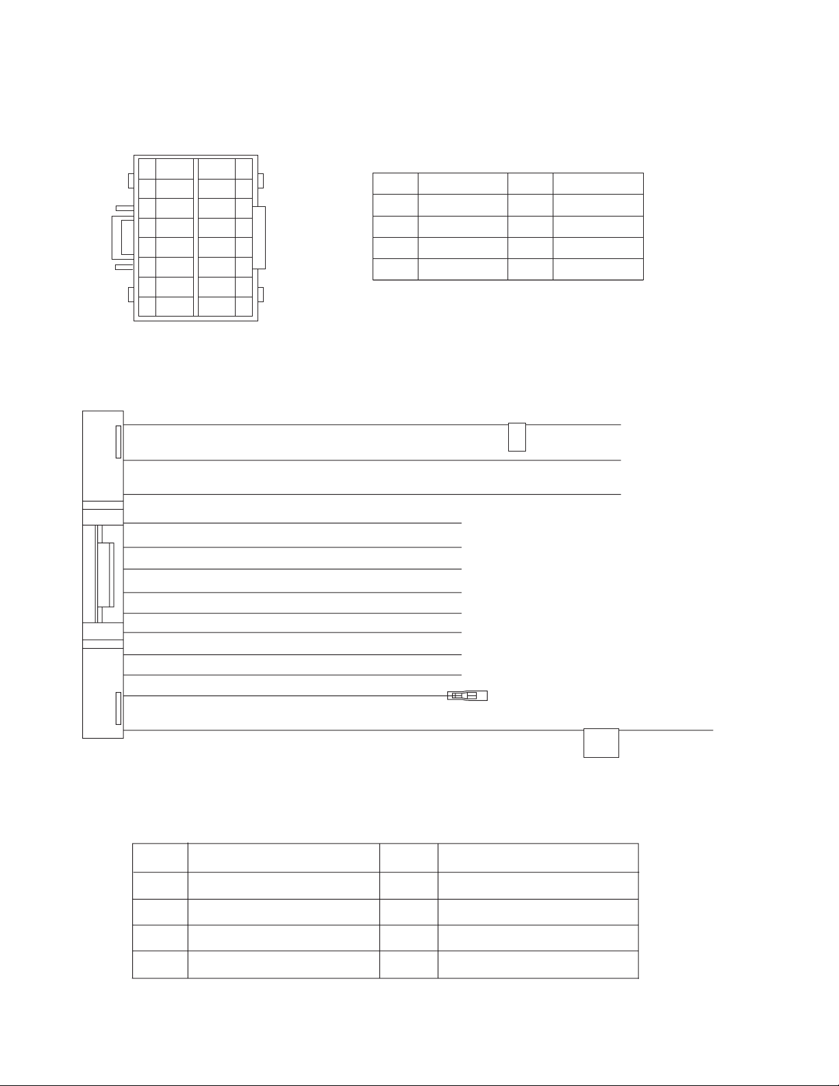
5.1 16PIN CORD DIAGRAM (for KD-ADV5380, KD-DV5300)
GN
8
7
6
5
4
3
2
1
GN/BK
VI/BK
BL/WH
VI
NC
RD
BK
WH
WH/BK
GY/BK
GY
NC
YG
NC
YL
9
10
11
12
13
14
15
16
BK
RD
BL
WH
Black
Red
Blue
White
GN
VI
GY
YL
YG
Green
Violet
Gray
Yellow
Yellow Green
1 BK
16 YL
2 RD
9 WH
10 WH/BK
12 GY
11 GY/BK
8 GN
7 GN/BK
5 VI
6 VI/BK
3 BL/WH
14 YG
GND
MEMORY
ACC
FL+
FL-
FR+
FR-
RL+
RL-
RR+
RR-
REMOTE
PARKING
GND
PARKING
BRAKE
1-40 (No.MA308)
RR
FR
FL
RL
REMOTE
Rear Right
Front Right
Front Left
Rear Left
Remote
ACC
GND
MEMORY
PARKING
ACC Line
Ground
Memory Backup Battery+
Parking Brake
Page 41

5.2 16 PIN CORD DIAGRAM (for KD-DV5301, KD-DV5302, KD-DV5307, KD-DV5308)
8
7
6
5
4
3
2
1
16 YL
13 BR
10 WH/BK
14 YG
GN
GN/BK
VI/BK
VI
NC
BL/WH
RD
BK
7 RD
1 BK
3 BL/WH
8 GN
7 GN/BK
5 VI
6 VI/BK
9 WH
12 GY
11 GY/BK
WH
WH/BK
GY/BK
GY
BR
YG
NC
YL
9
10
11
12
13
14
15
16
ACC
MEMORY
GND
REMOTE
TEL
RL+
RL-
RR+
RR-
FL+
FL-
FR+
FR-
PARKING
BK
RD
BL
WH
BR
Black
Red
Blue
White
Brown
GN
VI
GY
YL
YG
TEL MUTING
Green
Violet
Gray
Yellow
Yellow Green
RD
1
3
5
7
RD 7
YL 4
NC
NC
BL/WH
RD
8
5
2
7
8
1
2
5
6
3
4
BR
YL
NC
BK
2
4
6
8
PARKING
BRAKE
RR
FR
FL
RL
REMOTE
Rear Right
Front Right
Front Left
Rear Left
Remote
ACC
TEL
GND
MEMORY
PARKING
ACC Line
Telephone Muting
Ground
Memory Backup Battery+
Parking Brake
VI/BK
GY/BK
WH/BK
GN/BK
2
4
6
8
VI
1
3
GY
5
WH
GN
7
(No.MA308)1-41
Page 42

5.3 16PIN CORD DIAGRAM (for KD-DV5304, KD-DV5305, KD-DV5306, KD0DV4304, KD-DV4305, KD-DV4306)
GN
8
7
6
5
4
3
2
1
GN/BK
VI/BK
BL/WH
VI
BL
RD
BK
WH
WH/BK
GY/BK
GY
NC
YG
NC
YL
10
11
12
13
14
15
16
9
BK
RD
BL
WH
Black
Red
Blue
White
GN
VI
GY
YL
YG
Green
Violet
Gray
Yellow
Yellow Green
1 BK
16 YL
2 RD
9 WH
10 WH/BK
12 GY
11 GY/BK
8 GN
7 GN/BK
5 VI
6 VI/BK
3 BL/WH
4 BL
14 YG
GND
MEMORY
ACC
FL+
FL-
FR+
FR-
RL+
RL-
RR+
RR-
REMOTE
ANT
PARKING
REMOTE OUT
POWER ANTENNA
GND
PARKING
BRAKE
1-42 (No.MA308)
RR
FR
FL
RL
REMOTE
Rear Right
Front Right
Front Left
Rear Left
Remote
ACC
GND
MEMORY
PARKING
ANT
ACC Line
Ground
Memory Backup Battery+
Parking Brake
Auto Antenna
Page 43

5.4 16 PIN CORD DIAGRAM (for KD-DV5388, KD-DV4388)
WH
GN
8
7
6
5
4
3
2
1
GN/BK
VI/BK
VI
BL
BL/WH
RD
BK
WH/BK
GY/BK
GY
NC
YG
NC
YL
10
11
12
13
14
15
16
9
BK
RD
BL
WH
BR
Black
Red
Blue
White
Brown
GN
VI
GY
YL
YG
Green
Violet
Gray
Yellow
YellowGreen
1
NC
NC
3
5
BL
7
RD
NC
YL
NC
BK
2
4
6
8
2
16
1
4
8
7
5
6
9
10
12
11
14
RD1
YL1
BK
BL
GN
GN/BK
VI
VI/BK
WH
WH/BK
GY
GY/BK
YG
RD3
RD2
YL 2
7
4
8
5
7
8
1
2
5
6
3
4
3
BL/WH
VI/BK
GY/BK
WH/BK
GN/BK
2
4
6
8
VI
1
3
GY
5
WH
GN
7
(No.MA308)1-43
Page 44

Victor company of Japan, Limited
Mobile Entertainment Business Group Mobile Entertainment Category 10-1,1chome,Ohwatari-machi,Maebashi-city,Gumma-ken, 371-8543,Japan
(No.MA308)
Printed in Japan
VPT
 Loading...