


 Loading...
T60xDFH-4 and T60xDFH-4+PIR Series Thermostat Controllers with Dehumidification and Occupancy Sensing Capability
Installation Instructions
Part No. 24-9890-951, Rev. A
Issued August 17, 2011
T601DFH-4, T602DFH-4, T603DFH-4, T604DFH-4, T605DFH-4, Supersedes October 15, 2009
T601DFH-4+PIR, T602DFH-4+PIR, T603DFH-4+PIR, T604DFH-4+PIR, T605DFH-4+PIR
Refer to the QuickLIT Web site for the most up-to-date version of this document.
Applications
The T60xDFH-4 and T60xDFH-4+PIR Series Thermostat Controllers provide control of twoor four-pipe fan coils, cabinet unit heaters, or other equipment. These thermostat controllers provide on/off, floating, or proportional 0 to 10 VDC control outputs; three speeds of fan control; and dehumidification capability. The T60xDFH-4+PIR Series Thermostat Controllers have occupancy sensing capability built into the device. These are stand-alone devices that maximize up to 30% energy savings in high-energy usage light commercial buildings, such as schools and hotels, during occupied times by using additional Stand-By setpoints. See the
Occupancy Sensor Operation – T60xDFH-4+PIR Thermostat Controllers section for more information.
The non-programmable T60x Series Thermostat Controllers provide the user access to parameters such as system mode, fan mode, and temperature setpoints. Additionally, the T60x Series has over 20 configurable parameters enabling the thermostat controllers to adapt to a variety of applications.
All T60x Series Thermostat Controllers use an intuitive, plain text, menu-driven backlit display that makes setup and operation quick and easy. The T60x Series also employ a unique, Proportional-Integral (PI) time-proportioning algorithm that virtually eliminates temperature offset associated with traditional, differential-based thermostat controllers.
IMPORTANT: The T60xDFH-4 and T60xDFH-4+PIR Series Thermostat Controllers are intended to provide an input to equipment under normal operating conditions. Where failure or malfunction of the thermostat controller could lead to personal injury or property damage to the controlled equipment or other property, additional precautions must be designed into the control system. Incorporate and maintain other devices, such as supervisory or alarm systems or safety or limit controls, intended to warn of or protect against failure or malfunction of the thermostat controller.
North American Emissions Compliance
United States
This equipment has been tested and found to comply with the limits for a Class A digital device pursuant to Part 15 of the FCC Rules. These limits are designed to provide reasonable protection against harmful interference when this equipment is operated in a commercial environment. This equipment generates, uses, and can radiate radio frequency energy and, if not installed and used in accordance with the instruction manual, may cause harmful interference to radio communications. Operation of this equipment in a residential area is likely to cause harmful interference, in which case the user will be required to correct the interference at his/her own expense.
Canada
This Class (A) digital apparatus meets all the requirements of the Canadian Interference-Causing Equipment Regulations.
Cet appareil numérique de la Classe (A) respecte toutes les exigences du Règlement sur le matériel brouilleur du Canada.
Installation
Location Considerations
Locate the T60x Series Thermostat Controller:
•on a partitioning wall, approximately 5 ft (1.5 m) above the floor in a location of average temperature
•away from direct sunlight, radiant heat, outside walls, outside doors, air discharge grills, or stairwells; and from behind doors
•away from steam or water pipes, warm air stacks, unconditioned areas (not heated or cooled), or sources of electrical interference
For integrated Passive Infrared (PIR) models, be sure that the thermostat controller is located centrally, where occupant movement is abundant.
T60xDFH-4 and T60xDFH-4+PIR Series Thermostat Controllers with Dehumidification |
1 |
and Occupancy Sensing Capability Installation Instructions |
|
Note: Allow for vertical air circulation to the thermostat controller.
To install the thermostat controller:
1.Use a Phillips-head screwdriver to remove the security screw if it is installed on the bottom of the thermostat controller cover.
Note: Normally, the security screw comes packaged separately in a plastic bag with the thermostat controller. Skip this step if the screw is not installed on the bottom of the cover.
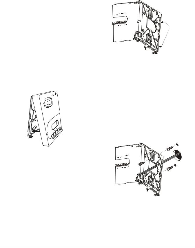
2.Pull the bottom edge of the thermostat controller cover and open the thermostat controller as illustrated in Figure 1.
Note: PIR models have a wiring connection between the cover and the Printed Circuit Board (PCB). This connection allows for proper wiring of the occupancy sensor. Carefully remove the wiring connection from the PCB by pulling up on the connector block. Do not attempt to remove the connector block by pulling on the wires.
<![if ! IE]><![endif]>FIG:cvr_rmvl
Figure 1: Removing the
Thermostat Controller Cover
(T60xDFH-4+PIR Model Shown)
3.Carefully pull the locking tabs on the right side of the thermostat controller mounting base and unlock the PCB. Open the PCB to the left as illustrated in Figure 2.
4.Pull approximately 6 in. (152 mm) of wire from the wall and insert the wire through the hole in the thermostat controller mounting base.
5.Align the thermostat controller mounting base on the wall and use the base as a template to mark the two mounting hole locations.
Note: Be sure to position the thermostat controller mounting base so that the arrow on the base points upward to indicate the top of the thermostat controller.
PCB
 Locking
Tabs
<![if ! IE]><![endif]>FIG:prcrctbrd
Figure 2: Opening the
Thermostat Controller PCB
6.Drill a 3/16 in. (5 mm) hole at each of the two marked locations and tap nylon anchors (included with the thermostat controller) flush to the wall surface.
Note: Other means of anchoring the device may be desired, depending on the wall medium.
7.Position the thermostat controller mounting base on the wall and use the two mounting screws (included with the thermostat controller) to secure the base to the wall surface as illustrated in Figure 3.
Note: Be careful not to overtighten the mounting screws.
<![if ! IE]><![endif]>FIG:mntbs
Figure 3: Securing the Thermostat Controller Mounting Base to the Wall
8.Swing the PCB back to the right and carefully snap it into the locking tabs on the thermostat controller mounting base.
2T60xDFH-4 and T60xDFH-4+PIR Series Thermostat Controllers with Dehumidification and Occupancy Sensing Capability Installation Instructions
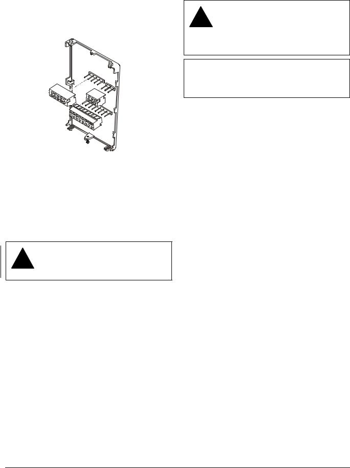
9.Remove the screw terminal blocks that are attached to a disposable adhesive. Figure 4 illustrates the locations of the screw terminal blocks on the thermostat controller.
s k c l b _ l n m r t : G I F
Figure 4: Removing the Screw Terminal Blocks
Wiring
When an existing thermostat controller is replaced, remove and label the wires to identify the terminal functions. When a T60x Series Thermostat Controller is replaced, simply remove the old screw terminal blocks and reinsert them onto the PCB of the replacement thermostat controller.
CAUTION: Risk of Electric Shock.
!Disconnect the power supply before making electrical connections to avoid electric shock.
CAUTION: Risk of Property Damage.
!Do not apply power to the system before checking all wiring connections. Short circuited or improperly connected wires may result in permanent damage to the equipment.
IMPORTANT: Make all wiring connections in accordance with local, national, and regional regulations. Do not exceed the electrical ratings of the T60x Series Thermostat Controller.
To wire the thermostat controller:
1.Strip the ends of each wire a 1/4 in. (6 mm) and connect them to the appropriate screw terminals as indicated in Table 1 and Figure 5 through Figure 9.
2.Carefully push any excess wire back into the wall.
Note: Seal the hole in the wall with fireproof material to prevent drafts from affecting the ambient temperature readings.
3. Reinsert the screw terminal blocks onto the PCB.
Note: If multiple wires are inserted into the terminals, be sure to properly twist the wires together prior to inserting them into the terminal connectors.
4.For PIR models, carefully reattach the PIR connector to the PCB.
5.Reattach the thermostat controller cover to the mounting base (top side first).
6.Use a Phillips-head screwdriver to reinstall the security screw on the bottom of the thermostat controller cover if desired. The security screw comes packaged separately in a plastic bag with the thermostat controller.
T60xDFH-4 and T60xDFH-4+PIR Series Thermostat Controllers with Dehumidification and Occupancy |
3 |
Sensing Capability Installation Instructions |
|

Table 1: Terminal Identification (See Figure 5.)
Terminal |
|
Terminal Label |
|
Function |
Number |
|
|
|
|
T601DFH-4, |
T602DFH-4, |
T604DFH-4, |
|
|
|
T601DFH-4+PIR |
T602DFH-4+PIR, |
T604DFH-4+PIR, |
|
|
(On/Off Control) |
T603DFH-4, |
T605DFH-4, |
|
|
|
T603DFH-4+PIR |
T605DFH-4+PIR |
|
|
|
(On/Off or |
(Proportional 0 to |
|
|
|
Floating Control) |
10 VDC Control) |
|
1 |
Fan-H |
Fan-H |
Fan-H |
Fan On – High |
|
|
|
|
|
2 |
Fan-M |
Fan-M |
Fan-M |
Fan On – Medium |
|
|
|
|
|
3 |
Fan-L |
Fan-L |
Fan-L |
Fan On – Low |
|
|
|
|
|
4 |
24 V~ Hot |
24 V~ Hot |
24 V~ Hot |
24 VAC from Transformer |
|
|
|
|
|
5 |
24 V~ Com |
24 V~ Com |
24 V~ Com |
24 VAC (Common) from Transformer |
|
|
|
|
|
6 |
BO5 Aux |
BO5 Aux |
BO5 Aux |
Aux BO (Auxiliary Output) |
|
|
|
|
|
7 |
BO5 Aux |
BO5 Aux |
BO5 Aux |
Aux BO (Auxiliary Output) |
|
|
|
|
|
8 |
BO3 |
BO3 |
Blank |
Open Heat |
|
|
|
|
|
9 |
Blank |
BO4 |
AO2 |
Close Heat |
|
|
|
|
|
10 |
Blank |
BO1 |
AO1 |
Open Cool |
|
|
|
|
|
11 |
BO2 |
BO2 |
Blank |
Close Cool |
|
|
|
|
|
12 |
BI1 |
BI1 |
BI1 |
Configurable Binary Input 1 |
|
|
|
|
|
13 |
RS |
RS |
RS |
Remote Room Temperature Sensor |
|
|
|
|
|
14 |
Scom |
Scom |
Scom |
Sensor Common |
|
|
|
|
|
15 |
BI2 |
BI2 |
BI2 |
Configurable Binary Input 2 |
|
|
|
|
|
16 |
UI3 |
UI3 |
UI3 |
Configurable Universal Input 3 |
|
|
|
|
|
4T60xDFH-4 and T60xDFH-4+PIR Series Thermostat Controllers with Dehumidification and Occupancy Sensing Capability Installation Instructions
|
|
|
|
|
Separate 24 VAC |
|
|
|
|
|
|
|
|
|
|
|
|
Power and Fan |
|
Power Source for Auxiliary Output |
|
|
|
|
|
|
|
|
|
||
|
|
|
(24 VAC Maximum) |
Five-Pole |
|
|
|
Three-Pole |
|
||||||
|
|
|
|
|
|
|
|
|
|
|
|||||
|
|
|
|
|
|
|
Left Top Connector |
|
|
||||||
|
|
|
|
|
|
|
|
Right Top |
|
||||||
|
24 V~ |
|
|
|
|
|
|
|
|
|
|
|
|||
24 V~ |
Fan |
Fan |
Fan |
BO5 |
BO5 |
Fan |
Fan |
Fan |
24 V~ |
24 V~ |
Connector |
|
|||
Hot |
Com |
-L |
-M |
-H |
Aux |
Aux |
|
|
|
|
|||||
|
|
-H |
-M |
-L |
Hot |
Com |
BO5 BO5 |
BO3 |
|||||||
|
|
|
|
|
|
|
|
|
|
|
|
||||
|
|
|
|
|
|
Aux |
1 |
2 |
3 |
4 |
5 |
Aux |
Aux |
|
|
|
|
|
|
|
|
|
|
|
|
||||||
|
|
|
|
|
|
|
|
|
|
|
|
6 |
7 |
8 |
|
|
|
|
|
|
|
|
|
|
|
|
|
|
|||
|
|
|
|
|
|
|
Eight-Pole Bottom Connector |
|
|
|
|||||
|
|
|
|
|
|
|
BO4/ |
BO1/ |
BO2 |
BI1 |
RS |
Scom |
BI2 |
UI3 |
|
|
|
|
|
|
|
|
AO2 |
AO1 |
|
|
|
|
|
|
|
|
|
|
|
|
|
|
9 |
10 |
11 |
12 |
13 |
14 |
15 |
16 |
|
|
|
|
|
|
|
|
Independent |
|
|
|
|
|
|
|
|
|
|
|
Contacts |
|
|
|
|
|
|
|
|
|
|
|
• Reheat |
|
|
|
|
24 VAC |
|
|
|
|
|
• Lighting |
|
|
|
|
|
|
|
|
|
|
• On/Off Actuation |
|
|
||||
Thermostat Controller |
|
- OR - |
|
|
|
• Exhaust Fan |
|
|
|
||
Power |
|
|
Same 24 VAC |
|
|
|
|
|
|||
|
Power and Fan |
|
|
|
|
|
|
||||
|
|
Power Source for Auxiliary Output |
|
Remote Inputs |
|
Voltage-Free |
|||||
|
|
|
|
|
(24 VAC Maximum) |
|
|
||||
|
|
|
|
|
|
|
Contact |
||||
|
|
|
|
|
|
|
|
|
|
|
|
24 V~ |
24 V~ |
Fan |
Fan |
Fan |
|
|
|
|
|
|
• Door |
|
|
|
|
|
|
• Remote |
|||||
Hot |
Com |
-L |
-M |
-H |
BO5 |
BO5 |
BI1 |
Scom |
BI2 |
UI3 |
|
|
|
Override |
|||||||||
|
|
|
|
|
Aux |
Aux |
|
|
|
|
|
|
|
|
|
|
|
|
|
|
• Filter Alarm |
||
|
|
|
|
|
|
|
|
|
|
|
|
|
|
|
|
|
|
|
|
|
|
|
• Service Alarm |
|
|
|
|
|
|
Aux |
|
|
|
|
Voltage-Free |
|
|
|
|
|
|
|
|
|
|
|
|
|
|
|
|
|
|
|
Voltage-Free |
|
|
|
Contact |
|
|
|
|
|
|
|
Contact |
|
- OR - |
|
• COC/NH |
|
|
|
|
|
|
|
• Remote NSB |
|
|
Normally Heat |
|
|
|
|
|
|
|
|
• Motion |
|
|
|
Closed Contact |
|
|
|
|
|
|
|
• Window |
|
|
|
= Cold Water |
|
|
|
|
|
|
|
|
|
|
|
• COC/NC |
|
|
|
|
|
|
|
|
|
|
|
Normally Cool |
|
|
|
|
|
|
|
|
Supply Sensor |
|
Closed Contact |
|
|
|
|
|
|
|
|
|
|
= Hot Water |
||
|
|
|
|
|
|
|
|
Changeover Sensor |
|||
|
|
|
|
|
|
|
|
|
|||
24 VAC |
|
|
|
|
|
|
|
|
|
<![if ! IE]> <![endif]>FIG:wrng |
|
Thermostat Controller |
|
|
|
|
|
|
|
|
|
|
|
Power |
|
|
|
|
|
|
|
|
|
|
|
Figure 5: Wiring the T60xDFH-4 or T60xDFH-4+PIR Series Thermostat Controller (See Table 1.)
T60xDFH-4 and T60xDFH-4+PIR Series Thermostat Controllers with Dehumidification and Occupancy |
5 |
Sensing Capability Installation Instructions |
|

BO2 |
24 V~ |
24 V~ |
BO3 |
24 V~ |
24 V~ |
|
Hot |
Com |
N.C. |
Hot |
Com |
|
|
|
Cooling |
|
|
|
|
|
Valve |
|
|
|
|
|
N.O. |
|
|
|
|
|
Heating |
|
|
|
|
|
Valve |
|
|
Two-Pipe Applications |
|
Four-Pipe Applications |
|
||
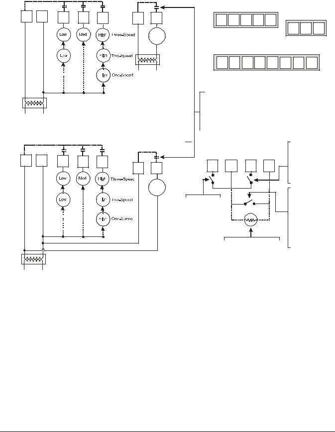
Figure 6: Wiring T601DFH-4 Thermostat Controllers for On/Off Control
<![endif]>FIG:T601dfh3ooc
or |
24 V~ |
24 V~ |
or |
or |
24 V~ |
24 V~ |
Cooling |
|
Hot |
Com |
|||
|
Hot |
Com |
|
|
|
|
|
|
|
Valve |
|
|
|
Heating
Valve
Two-Pipe Applications |
Four-Pipe Applications |
<![endif]>FIG:T6023dfh3ooc
Figure 7: Wiring T602DFH-4 and T603DFH-4 Thermostat Controllers for On/Off Control
BO1 |
BO2 |
24 V~ |
24 V~ |
BO1 |
BO2 |
BO3 |
BO4 |
24 V~ |
24 V~ |
|
|
Hot |
Com |
Cooling |
|
|
|
Hot |
Com |
|
|
|
|
|
|
|
|
|
|
|
|
|
|
Valve |
|
|
|
|
|
Heating/Cooling |
|
<![if ! IE]> <![endif]>FIG:T6023dfh3fc |
Valve |
|
|
|
|
|
|
Heating |
|
|
Valve |
|
Two-Pipe Applications |
Four-Pipe Applications |
Figure 8: Wiring T602DFH-4 and T603DFH-4 Thermostat Controllers for Floating Control
AO1 |
24 V~ |
24 V~ |
|
Hot |
Com |
||
|
|||
Heating/Cooling |
|
|
|
Valve |
|
|
AO1 |
AO2 |
24 V~ |
24 V~ |
|
Hot |
Com |
|||
|
|
|||
Cooling |
|
|
|
|
Valve |
|
|
|
|
Heating |
|
|
<![if ! IE]> <![endif]>FIG:T6045dfh3prp |
|
|
|
|
||
Valve |
|
|
|
Two-Pipe Applications |
Four-Pipe Applications |
Figure 9: Wiring T604DFH-4 and T605DFH-4 Thermostat Controllers for Proportional Control
6T60xDFH-4 and T60xDFH-4+PIR Series Thermostat Controllers with Dehumidification and Occupancy Sensing Capability Installation Instructions
Setup and Adjustments
Thermostat Controller Operation Overview
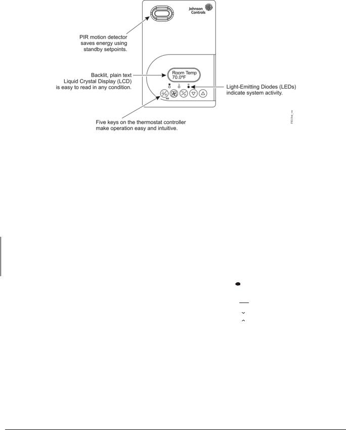
Figure 10: Front Cover of Thermostat Controller (T60xDFH-4+PIR Model Shown)
Thermostat Controller User Interface Keys
The T60x Series Thermostat Controller user interface consists of five keys on the front cover (as illustrated in Figure 10). The function of each key is as follows:
•Use the MODE key to toggle among the system modes available, as defined by selecting the appropriate operation sequence in the Installer Configuration Menu (for example, Off, Heat, Cool, Auto).
Note: If the automatic changeover function (auto function) is enabled in the sequence of operation (SeqOpera), then automatic changeover heating or cooling demand overrides the mode when
MODE = off.
•Use the FAN key to toggle among the fan modes available, as defined by selecting the appropriate fan menu options defined in the Installer Configuration Menu (for example, Low, Med, High, Auto).
•Use the UP/DOWN arrow keys to change the configuration parameters and to activate a setpoint adjustment.
Backlit LCD
The T60x Series Thermostat Controllers include a 2-line, 8-character backlit display. Low-level backlighting is present during normal operation, and it brightens when any user interface key is pressed. The backlight returns to low level when the thermostat controller is left unattended for 45 seconds.
LEDs
Three LEDs are included to indicate the fan status, call for heat, or call for cooling:
•The fan LED 
 is on when the fan is on.
•The heat LED 

 is on when heating is on.
•The cool LED 

 is on when cooling is on.
•Use the °C/°F key to change the temperature scale to either Celsius or Fahrenheit and allow access to the Installer Configuration Menu. See the
Configuring the T60xDFH-4 and T60xDFH-4+PIR Series Thermostat Controller section.
Integrated PIR Sensor – T60xDFH-4+PIR Thermostat Controllers
The integrated PIR sensor allows for automatic switching between fully adjustable Occupied and Stand-By temperature setpoints without user interaction. This feature generates incremental energy savings during scheduled occupied periods while the space is unoccupied.
T60xDFH-4 and T60xDFH-4+PIR Series Thermostat Controllers with Dehumidification and Occupancy |
7 |
Sensing Capability Installation Instructions |
|
Loading...