


Low Ambient Pressure Kit
ACCESSORY KIT INSTALLATION MANUAL
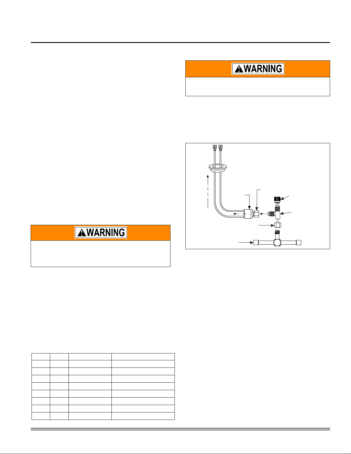
TO LOW VOLTAGE BOX
PRESSURE
SWITCH
FLARE
FITTING
TEE FITTING
ASSEMBLY
VALV E
CAP
FLARE FITTING
WITH DEPRESSOR
BRASS REFRIGERANT
VALVE (Liquid)
LOW AMBIENT PRESSURE KIT MODEL 2LA06700224 & 2LA06700424
FOR MODELS: SPLIT SYSTEM AIR CONDITIONERS AND HEAT PUMPS
GENERAL INFORMATION
The low ambient pressure switch kit (2LA06700224) for R-22
models and 2LA06700424 for R-410A models) are designed to
regulate condenser liquid pressure at low outdoor ambient temperatures by controlling the airflow over the condenser. The low
ambient pressure kit will energize the outdoor motor when the
liquid line pressure reaches 300 +/-10 PSIG for R-22 models
and 360 +/-10 PSIG for R-410A models, it will stop the motor
when the pressure falls below 150 +/- PSIG for R-22 models
and 240 +/- PSIGfor R-410A models.
The supplied relay has a normally-closed contact. As the liquid
pressure falls below the low setting of the pressure switch, the
relay will energize and open the normally-closed contact, thus
breaking the circuit of the fan motor, causing it to stop.As the
liquid pressure increases above the high pressure setting of the
pressure switch, the relay will de-energize and close the normally-closed contact, re-energizing the fan. Heat pumps use
the 4-way reversing valve power for the control circuit of the low
ambient kit in the order to disable low ambient fan cycling in the
heat mode.
When applying this kit, a TXV must be used on the indoor coiland a crankcase heater should be added. This will guard
against liquid migration and hard starts which could lead to premature failure of the compressor.
PRE-INSTALLATION INFORMATION AND
INSTRUCTIONS
INSTALLATION
Make sure the electric power is shut-off. Failure to disconnect the electric power could result in electric
shock and severe injury from the outdoor fan.
1. Disconnect power to the unit.
2. Remove the control access panel.
3. Locate the liquid line base valve and remove the cap off the
schrader valve.
4. Attach the tee fitting and pressure switch to the liquid line
base valve , as shown in Figure 1.
Improper installation, adjustment service, or maintenance can cause injury or property damage; therefore, only a qualified installer or qualified service
personnel should perform the conversion.
1. With this kit, only use motors that are single phase, permanent split, capacitor type or shaded pole motors.
2. Line Voltage Range: 120 to 600 Volts AC.
3. Wiring must comply with all local and national electric
codes.
4. Crankcase heater should be applied in conjunction with
this kit.
INSPECTION
The following list details the parts included in this kit. Inspect
the kit to ensure that all the parts are included.
TABLE 1:
ITEM QTY. PART NO. DESCRIPTION
Johnson Controls Unitary Products 513433-UAI-A-0509
Source 1
1 1 513033 Pressure Switch
2 1 473-19101-000 Relay
3 2 — Black Wire
4 1 — Black Wire
5 2 021-17310-000 Screw #10-16x3/8
62 — Wire Tie
7 1 6666 Tee Fitting
8 1 1216-175 Line Splice Connection
FIGURE 1: Pressure Switch Assembly
5. Tighten all connections using a 9/16” wrench. Check the
connections between the switch and schrader valve for
leaks.
6. Route the pressure switch wires through the grommet
located on the bottom of the control box. Secure the wires
away from hot refrigerant lines with a wire tie.
7. Secure the relay with #10 screws included in the kit. Use
the relay to mark and drill two (9/64 inch) holes so that the
relay is 1/2 inch away from high voltage wiring and components.
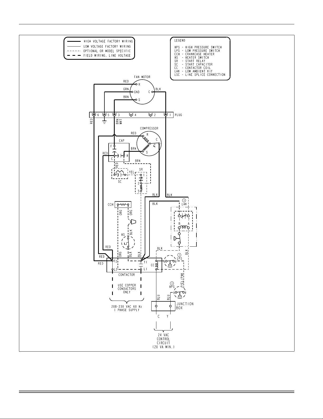
8. To wire the low ambient pressure kit:
a. For 1 and 3 phase AC, use Figure 2.
b. For 1 and 3 phase HP, use Figure 3*.
*To connect wires to “O” and “C” in the low voltage box, cut off
wire connections from the additional black wires provided in kit
and strip insulation from wire. Use existing wire nuts to connect
into “O” and “C” junction.
9. Replace the control access panel and restore power to the
unit.
10. With the unit running in the cooling mode, make sure the
outdoor fan operates properly and replace all schrader
valve caps.
513433-UAI-A-0509
FIGURE 2: Wiring Connections for Air Conditioning Units
2 Johnson Controls Unitary Products
 Loading...