


DX-9100
Table of contents
 Loading...
FANs 636.4, 1628.4
Configuration Guides Section
Configuration Guide
Issue Date 0900
© 2000 Johnson Controls, Inc.
1
Code No. LIT-6364030 www.johnsoncontrols.com
DX-9100 Extended Digital Plant Controller Page 5
• Introduction *5
• Hardware Configuration 10
Software Configuration 11
• DX-9100 Software Elements 11
• Configuration Tools 11
• Configuring the Controller 14
• DX-9100 Controller Selection 15
• DX-9100 Global Data 15
• Configuration Number (Version 1.1 or Later) 17
• Password Feature (Versions 1.4, 2.3, 3.3, or Later) 17
• Analog Input Configuration 18
• Digital Input Configuration 25
• Analog Output Configuration 26
• Digital Output Configuration 32
• DO: Output Type 34
• Constants and Result Status 40
• Extension Module Configuration *42
• Network Analog Input Configuration (Version 3 Only) *51
• Network Digital Input Configuration (Version 3 Only) 52
• Network Analog Output Configuration (Version 3 Only) 53
• Network Digital Output Configuration (Version 3 Only) 55
• Programmable Function Module Configuration 57
• Control Algorithm Theory 63
DX-9100 Configuration Guide
* Indicates those sections where changes have occurred since the last printing.

2
Configuration Guides—DX-9100 Configuration Guide
• Algorithm 01 - PID Control Module
Page
65
• Algorithm 02 - On/Off Control Module 78
• Algorithm 03 - Heating/Cooling PID Control Module (Dual PID) 86
• Algorithm 04 - Heating/Cooling On/Off Control Module (Dual On/Off) 98
• Numerical Calculation and Other Function Module Configurations 107
• Algorithm 11 - Average 107
• Algorithm 12 - Minimum Select 109
• Algorithm 13 - Maximum Select 111
• Algorithm 14 - Psychrometric Calculation °C 113
• Algorithm 15 - Psychrometric Calculation °F 116
• Algorithm 16 - Line Segment 119
• Algorithm 17 - Input Selector 121
• Algorithm 18 - Calculator 123
• Algorithm 19 - Timer Functions 125
• Algorithm 20 - Totalization 129
• Algorithm 21 - Comparator 133
• Algorithm 22 - Sequencer 136
• Algorithm 23 - Four Channel Line Segment (Version 1.1 or Later) 152
• Algorithm 24 - Eight Channel Calculator (Version 1.1 or Later) 154
• Time Program Functions 156
• Time Schedule Configuration 157
• Optimal Start/Stop Configuration 161
• Programmable Logic Control Configuration 174
• Dial-up Feature with an NDM *188
• Trend Log (Versions 1.4, 2.3, 3.3, or Later) 192
• Supervisory Mode Control Settings (General Module) *195
• Controller Diagnostics 204
• Power Up Conditions 204
• Download/ Upload *206
• Calibration Values 209
* Indicates those sections where changes have occurred since the last printing.

Configuration Guides—DX-9100 Configuration Guide
3
Appendix A: SX Tool Item Description and Tables Page 211
• Description of Items 211
• Item List 213
• Floating Point Numbers 215
• EEPROM Items 215
Appendix B: Item Structure 217
• General Module Items Structure *217
• Programmable Function Module Items Structure 223
• Analog Input Module Items Structure 226
• Analog Output Module Items Structure 228
• Digital Output Module Items Structure 229
• Extension Module Items Structure 230
• Time Scheduling Items Structure *236
• Optimal Start/Stop Items Structure 237
• Network Information Module Items Structure 238
• Network Digital Output Module Items Structure 239
• Network Analog Output Module Items Structure 241
• Network Digital Input Module Items Structure 243
• Network Analog Input Module Items Structure 244
Appendix C: Programmable Function Module Items 247
• Algorithm 1 - PID Controller 247
• Algorithm 2 - On/Off Controller 249
• Algorithm 3 - Heating/Cooling PID Controller 251
• Algorithm 4 - Heating/Cooling On/Off Controller 253
• Algorithm 11 - Average Calculation 256
• Algorithm 12 - Minimum Selection 257
• Algorithm 13 - Maximum Selection 258
• Algorithm 14 - Psychrometric Calculation °C 259
* Indicates those sections where changes have occurred since the last printing.

4
Configuration Guides—DX-9100 Configuration Guide
• Algorithm 15 - Psychrometric Calculation °F
Page
260
• Algorithm 16 - Line Segment Function 261
• Algorithm 17 - Input Selector 262
• Algorithm 18 - Calculator 263
• Algorithm 19 - Timer Function 264
• Algorithm 20 - Totalization 266
• Algorithm 21 - Eight Channel Comparator 269
• Algorithm 22 - Sequencer 271
• Algorithm 23 - Four Channel Line Segment Function 274
• Algorithm 24 - Eight Channel Calculator 276
Appendix D: Logic Variables 279
• Description of Logic Variables 279
• Logic Variable Tables 280
Appendix E: Analog Items and Logic Variables for the
Trend Log Module *287
* Indicates those sections where changes have occurred since the last printing.

Configuration Guides—DX-9100 Configuration Guide
5
DX-9100 Extended Digital Plant
Controller
This document covers all three versions of the DX-9100 Extended Digital
Controller, including the DX-912x L
ON
W
ORKS
® version. They include:
Version 1 – provides up to eight output modules, which are configured to
give two analog outputs and six digital outputs (triacs).
Version 2 – provides six additional analog output modules, giving a total
of eight analog outputs.
Version 3 – the DX-912x L
ON
W
ORKS
version brings peer-to-peer
communication to the feature set of the Version 2 controller,
and enhanced alarm reporting capability when used as an
integral part of an Building Automation System (BAS).
In this document, BAS is a generic term, which refers to the
Metasys® Network, Companion™, and Facilitator™ supervisory systems.
The specific system names are used when referring to system-specific
applications.
The DX-9100 is the ideal digital control solution for multiple chiller or
boiler plant control applications, for the Heating, Ventilating, and Air
Conditioning (HVAC) process of air handling units or for distributed
lighting and related electrical equipment control applications. It provides
precise Direct Digital Control (DDC) as well as programmed logic control.
In a standalone configuration, the DX-9100 Controller has both the
hardware and software flexibility to adapt to the variety of control
processes found in its targeted applications. Along with its outstanding
control flexibility, the controller can expand its input and output point
capability by communicating with I/O Extension Modules on an expansion
bus, and provides monitoring and control for all connected points via its
built-in Light-Emitting Display (LED). Versions 1 and 2 can communicate
on the N2 Bus as well as on the System 91 Bus*, providing point control
to the full BAS Network or to the N30 system or Companion/Facilitator
System. The Version 3 controller uses the L
ON
W
ORKS
(Echelon®) N2 Bus
of the Metasys Control Module (NCM311 or NCM361 in Europe,
NCM300 or NCM350 elsewhere) in place of the N2 Bus.
*The terms System 91 Bus and Metasys Control Station are not used in North America.
Introduction
6
Configuration Guides—DX-9100 Configuration Guide
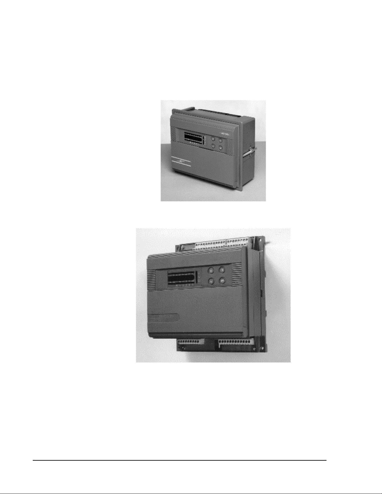
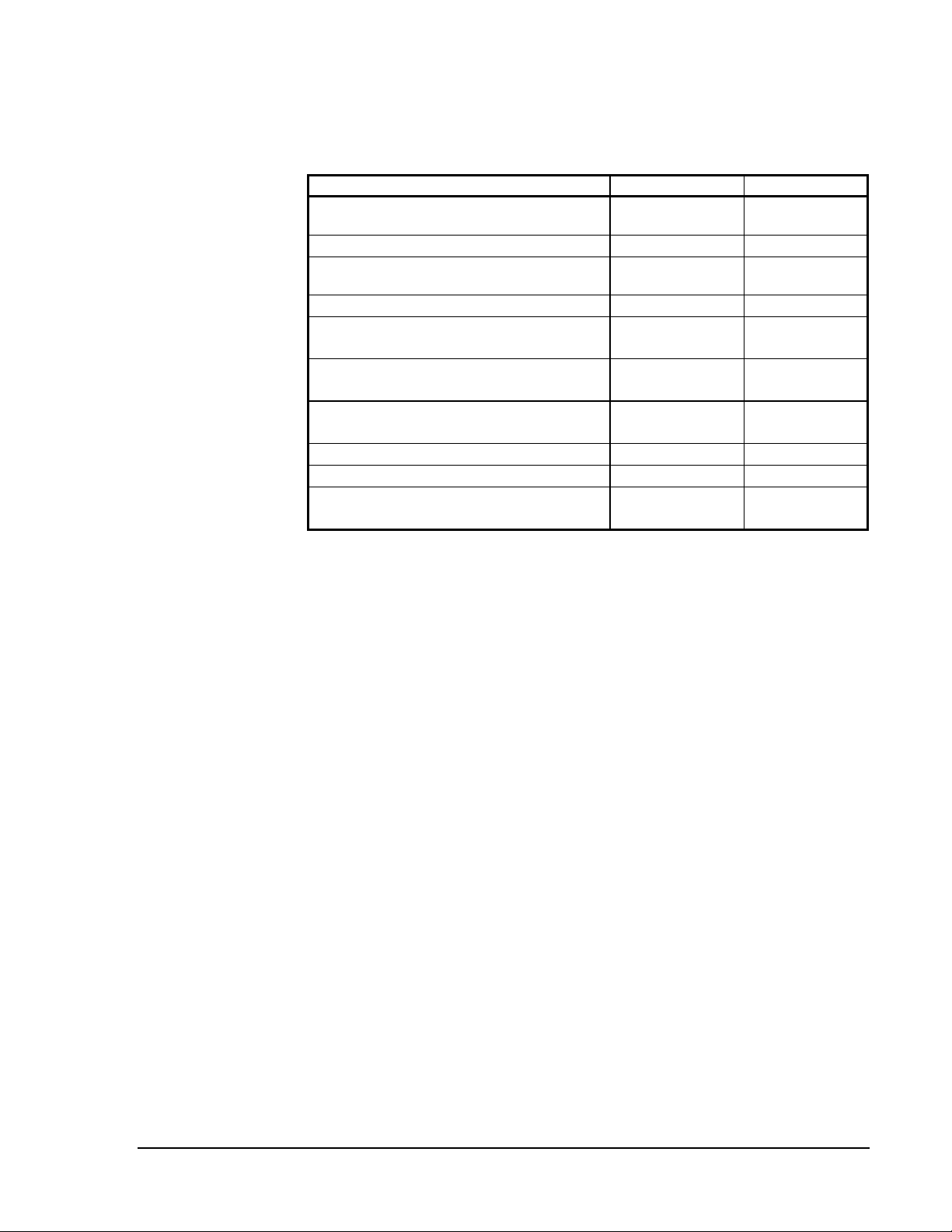
The DX-9100 has two packaging styles. In Version 1, all terminals for
field wiring are located within the controller enclosure. Versions 2 and 3
require a separate field wiring mounting base or cabinet door mounting
frame, which enables all field wiring to be completed before the controller
is installed.
Figure 1: Version 1 (DX-9100-8154)
Figure 2: DX-9100-8454 (Version 2)/DX-912x-8454 (Version 3)
with Mounting Base
Note: The mounting base differs for DX-9120 and DX-9121.

Configuration Guides—DX-9100 Configuration Guide
7
The DX-9100 processes the analog and digital input signals it receives,
using twelve multi-purpose programmable function modules, a software
implemented Programmable Logic Controller (PLC), time schedule
modules, and optimal start/stop modules; producing the required outputs
(depending on the module configuration), operating parameters, and
programmed logic.
Configuration of all versions of the DX-9100 Controller are achieved by
using a Personal Computer (PC) with GX-9100 Graphic Configuration
Software (Version 5 or later) supplied by Johnson Controls. Changes to
the configuration can be made by using an SX-9120 Service Module
(Version 3.1 or later).
The DX-9100 unit (Versions 1 and 2) has two communication links.
One is called the N2 Bus or Bus 91 (the term Bus 91 is not used in
North America) and is used to interface to a supervisory unit. The other
link is called the XT Bus and is used to expand the DX-9100 input/output
capability by interfacing up to eight XT-9100 or XTM-905 extension
modules. The DX-9100 input/output can be extended by up to 64 remote
input/outputs, analog or digital, depending on the type of the connected
extension modules and XP expansion modules.
Point connections are made on XP modules, which are monitored and
controlled by the XT-9100 or XTM-905 modules. For more details, refer
to the XT-9100 Technical Bulletin in the System 9100 Manual (FAN 636.4
or 1628.4). One XP module can provide either eight analog points or
eight digital points. Two XP modules connected to one extension module
provides eight analog and eight digital points, or sixteen digital points.
Version 1 or 2 of the DX-9100 can be used as a standalone controller or it
can be connected to a BAS through the RS-485 serial communications bus
(N2 Bus or Bus 91).
Version 3 of the controller (DX-912x-8454) brings peer-to-peer
communication to the feature set of the Version 2 controller, and enhanced
alarm reporting capability when used as an integral part of a Metasys BAS
Network.
The new communications features are provided by the L
ON
W
ORKS
Network, which enables Version 3 controllers to pass data from one to
another and to send event-initiated data to the NCM350 (NCM361 in
Europe) Network Control Module, in the BAS. The L
ON
W
ORKS
(Echelon)
N2 Bus is used in place of the N2 Bus, and the NCM300 or NCM350
(NCM311 or NCM361 in Europe) must be fitted with a L
ON
W
ORKS
(Echelon) driver card.
The Version 3 controller retains all the input/output point and control
capabilities of the Version 2 controller, including the point expansion
feature using extension modules and expansion modules.
Versions 1 and 2
(N2 Bus)
Version 3
(L
ON
W
ORKS
N2 Bus)

8
Configuration Guides—DX-9100 Configuration Guide
In addition to the Version 2 features, the Version 3 controller has network
input and output points, which can be configured to transmit and receive
data over the L
ON
W
ORKS
Bus. Each controller may have up to 16 network
analog input modules, 16 network analog output modules, 8 network
digital input modules, and 8 network digital output modules. While
network analog input and output modules each contain a single analog
value, the network digital input and output modules each contain 16 digital
states, which are transmitted as a block between controllers. The
transmission of point data is managed by the L
ON
W
ORKS
Network and is
independent of the supervisory functions of the BAS Network Control
Module (NCM). A network of Version 3 controllers can be installed to
share analog and digital data between controllers on a peer-to-peer basis; a
Network Control Module is not required unless the network is to be
supervised by a BAS.
Complex control strategies may now be performed in multiple DX-912x
controllers without the need for network data exchange routines in a
supervisory controller. Applications include the control of multiple,
interdependent air handling units, and large hot water or chilled water
generating plants with components distributed in various locations within
the building.
The Version 3 controller has been approved as a L
ON
M
ARK
device and
conforms to the L
ON
M
ARK
specification for network data transmission.
R
Figure 3: L
ON
M
ARK
Trademark
Further information about compatibility and interoperability with other
L
ON
M
ARK
devices may be requested from your local Johnson Controls
office.
L
ON
M
ARK
Compatibility
Configuration Guides—DX-9100 Configuration Guide
9
Refer to Table 1 for additional information on System 9100 controllers:
Table 1: Related Information
Document Title Code Number FAN
DX-9100 Extended Digital Controller
Technical Bulletin
LIT-6364020 636.4, 1628.4
DX-9100 Configuration Guide
LIT-6364030 636.4, 1628.4
GX-9100 Software Configuration Tool
User’s Guide
LIT-6364060 636.4, 1628.4
L
ON
W
ORKS
N2 Bus Technical Bulletin
LIT-6364100 636.4
XT-9100 Technical Bulletin
LIT-6364040
LIT-1628440
636.4
1628.4
XT-9100 Configuration Guide
LIT-6364050
LIT-1628450
636.4
1628.4
NDM Configurator Application Note
LIT-6364090
LIT-1628490
636.4
1628.4
Scheduling Technical Bulletin
LIT-636116 636
Point History Technical Bulletin
LIT-636112 636
SX-9100 Service Module User’s Guide
LIT-6364070
LIT-1628470
636.4
1628.4
Related
Information

10
Configuration Guides—DX-9100 Configuration Guide
For full details of the hardware configuration, refer to the DX-9100
Extended Digital Controller Technical Bulletin(LIT-6364020) and the
XT-9100 Technical Bulletin (LIT-6364040).
In summary, the DX-9100 has the following interfaces, inputs, and
outputs:
•
One N2 Bus (Bus 91) RS-485 port for BAS communication
•
One L
ON
W
ORKS
N2 Bus for BAS communication and peer-to-peer
communication with other controllers on the same bus (maximum of
30 controllers on one L
ON
W
ORKS
Bus)
•
One XT Bus (RS-485 port) for up to 8 extension modules and a
maximum of 64 inputs/outputs
•
One port for service module (SX-9120) communication
•
Eight digital input ports for connection to voltage-free contacts
•
Eight analog input ports; the DX-9100 accepts 0-10 VDC or 0-20 mA
signals from active sensors, or can be connected to Nickel 1000
(Johnson Controls or DIN standard), Pt1000, or A99 passive
RTD sensors, as selected via jumpers on the circuit board
•
Six isolated triac digital outputs to switch external 24 VAC circuits
with devices such as actuators or relays
•
Two analog output ports, 0-10 VDC or 0-20 mA, as selected via
jumpers on the circuit board; also, 4-20 mA may be selected by
configuration
•
Four analog outputs, 0-10 VDC or 0-20 mA, as selected via jumpers
on the circuit board; also, 4-20 mA may be selected by configuration
•
Four additional analog outputs, 0-10 VDC only
•
One RS-232-C port for local downloading and uploading software
configurations (N2 Bus protocol)
The software configuration determines how these inputs and outputs are
used, and their range and application.
The DX-9100 must be supplied with a 24 VAC power source. All models
are suitable for 50 Hz or 60 Hz through software configuration.
Hardware
Configuration
Versions 1 and 2
Version 3
All Versions
Version 1
Versions 2 and 3

Configuration Guides—DX-9100 Configuration Guide
11
Software Configuration
The DX-9100 is a microprocessor-based programmable controller. It has
the following software elements:
•
eight analog input modules
•
eight digital input modules
•
two analog output modules in Version 1;
eight analog output modules in Versions 2 and 3
•
six digital output modules
•
up to 64 additional inputs/outputs from up to 8 extension modules
•
twelve programmable function modules with algorithms for control
and calculation
•
eight analog constants and 32 digital constants
•
one programmable logic control module with 64 logic result statuses
•
eight time schedule modules
•
two optimal start/stop modules
•
sixteen network analog input modules
•
eight network digital input modules
•
sixteen network analog output modules
•
eight network digital output modules
A user configures the controller using the GX-9100 Graphic Software
Configuration Tool. The SX-9120 Service Module is used to troubleshoot
and adjust individual parameters. Techniques for both tools are described
in the following sections.
For complete documentation on both tools, see the GX-9100 Software
Configuration Tool User’s Guide and the SX-9120 Service Module User’s
Guide in FAN 636.4 or 1628.4.
Following is a brief description of the main features of the GX-9100
Software Configuration Tool. Note that the term, click on, means to
position the cursor on the module or menu and then press the appropriate
mouse button to select it.
Note: When using the GX Tool, after entering a parameter, always click
on OK to confirm.
DX-9100
Software
Elements
Version 3 Only
Configuration
Tools
12
Configuration Guides—DX-9100 Configuration Guide
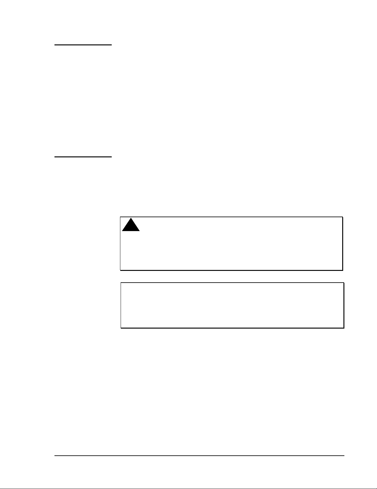
To enter data into a module displayed on the screen of the GX Tool, place
the cursor on the module, click once on the right mouse button and the
module menu will appear:
Data...
Delete
Connect... F5
Disconnect... F4
Show Selected
Show User Names
dxcon004
Figure 4: Module Menu
Place the cursor on Data and press either mouse button. A Data Window
appears containing all module data. Use the <Tab> key or mouse to move
the cursor from field to field. To make an entry, move the cursor to the
entry field and type in the information. To go to the second page in the
Data Window (if there is one), click on the Data-2 field. To return to the
first page, click on OK or Cancel.
To exit a window, click on OK to confirm entries, or Cancel to discard
them, while in the first page.
The following table shows the accuracy that may be lost due to rounding
errors. Numbers with a modulus of greater that 2047 may be rounded up or
down by 0.1% as follows:
Table 2: Rounding Errors
Range Rounding (+/-)
2048-4095
2
4096-8191
4
8192-16383
8
16384-32767
16
The rounding is due to the external communications bus protocol and does
not compromise the precision of the internal control processes.
Entering Data
into Modules
Entering Values

Configuration Guides—DX-9100 Configuration Guide
13
The Data Window contains User Name and Description entry fields. Up to
8 characters may be entered in the User Name field, and the Description
field can have up to 24 characters.
The Data Window also contains an Output Tag field for module outputs
(i.e., source points), which can be connected to another module as inputs
(destinations) and an Input Tag field for module inputs. To enter User
Names for outputs, position the cursor over the Output Tag field and press
the left mouse button once. To enter User Names for inputs, select the
Input Tag field.
To expand a module displayed on the screen of the GX Tool, in order to
view input/output connections, place the cursor over the module and
double-click on the left mouse button. Input connections appear in the left
column with @ attached to the Tag Name, and output connections are
shown in the right column, except for output modules where all
connections appear in one column. To close a module, place the cursor
over the expanded module and double-click on the left mouse button.
Connections are made using one of the four methods outlined below.
Note that only the first method is referred to later in this guide. An existing
connection must be disconnected before making a new connection.
•
The first method is to expand the source and destination modules by
moving the cursor to each module in turn and double-clicking the left
mouse button. Move the cursor over the desired output of the source
module and the cursor appears as an output arrow. Hold down the left
mouse button and drag the arrow to the desired destination input.
When the left mouse button is released, a connection line will be
drawn between the two modules.
•
The second method is to select the source module by positioning the
cursor over the module and pressing the left mouse button and then
the <F5> key. A list of the possible source output connections for that
module will be shown. Move the cursor to the desired output to select
it (it will appear highlighted) and click on OK (alternatively,
double-click on the desired output). To complete the connection,
select the destination module by pressing the left mouse button and
then the <F5> key. A list of the possible destination inputs for that
module will be shown. Select the desired destination from the dialog
box and click on OK (alternatively, double-click on the desired
destination). A connection line will be drawn between the
two modules.
Entering User
Names
Making
Connections

14
Configuration Guides—DX-9100 Configuration Guide
•
The third method is to select the source module by positioning the
cursor over it and pressing the right mouse button. The module menu
will appear. Select Connect and a list of possible source outputs for
that module will appear in a dialog box. Move the cursor to the
desired output to select it (it will appear highlighted) and click on OK
(alternatively, double-click on the desired output). Then select the
destination module by positioning the cursor on it and pressing the
right mouse button. The module menu will appear. Select Connect
and a list of possible destination inputs for that module will be shown.
Move the cursor to the desired input to select it and click on OK
(alternatively, double-click on the desired input). A connection line
will be drawn between the two modules.
•
The fourth method is to go to the destination module data window,
move the cursor to a connection field, press the <*> key on the
keyboard, and the available source output tags will be displayed for
selection.
Configuring the controller involves:
•
defining characteristics and parameters of the input and output
modules, the programmable function modules for control and
calculation, the extension modules, and the programmable logic
control module
•
defining connections between the modules in order to achieve the
desired sequence of control
•
setting the time scheduling, optimal start/stop, and realtime clock
parameters
Proceed in the following order:
1. Select the controller type (Versions 1, 2, or 3).
2. Define DX-9100 Global Data under the Edit menu.
3. Define Job Information under the Edit menu.
4. Define analog and digital input characteristics.
5. Define analog and digital output characteristics.
6. Define extension module structures and characteristics.
7. When applicable, define network inputs and outputs for the Version 3
controller (L
ON
W
ORKS
Bus).
8. Define programmable function module/algorithm characteristics.
9. Define time schedule and exception day settings.
10. Define programmable logic control module.
Configuring the
Controller

Configuration Guides—DX-9100 Configuration Guide
15
Select the controller version under the Controller menu:
•
DX Version 1.1, 1.2, 1.3, or
•
DX Version 1.4, or
•
DX Version 2.0, 2.1, 2.2, or
•
DX Version 2.3, 2.4 or
•
DX Version 3.0, 3.1, 3.2, or
•
DX Version 3.3 or 3.4
The SX Tool will display the controller type when first connected to the
controller. No user selection is required.
Via the GX Tool
At the menu bar at the top of the screen, select Edit-Global Data and a window
appears. Under Frequency, click on 50 or 60 Hz. Then click on OK to confirm
the setting. (To discard an entry, click on Cancel.)
Via the SX Tool
Under General Module, set bit X7 of Item DXS1 (RI.32):
•
X7 = 0 50 Hz power line
•
X7 = 1 60 Hz power line
When this flag is set to cancel or 1, the override-type Items listed below
are reset after each power up of the controller.
When set to maintained or 0, these override-type Items are maintained
through the power failure.
•
Shutoff mode request
•
Startup mode request
•
Enable Digital Output (Triac) Supervisory Control
•
Set Digital Output (Triac) On
•
Output Hold mode (Analog and Digital)
•
Programmable Function Module Hold
•
Time Schedule Module Hold mode
DX-9100
Controller
Selection
Via GX Tool
Via the SX Tool
DX-9100 Global
Data
Set Power Line
Frequency
(50 or 60 Hz)
Set Initialize on
Power Up Flag

16
Configuration Guides—DX-9100 Configuration Guide
Via the GX Tool
Select Edit-Global Data. Under Init. on Power Up, click on maintained
or cancelled.
Via the SX Tool
Under General Module, set bit X8 of Item DXS1 (RI.32):
X8 = 0 No initialization on power up (commands from BAS maintained)
X8 = 1 Initialization on power up (commands from BAS cancelled)
In the controller, four bytes are reserved for digital input counters and
accumulators in programmable modules. When the DX-9100 is connected
to a BAS, the counter type flag must be set to 0 because the system will
only read 15 bits (maximum reading of 32,767). For BASs that can read
four bytes, or for standalone applications, the flag may be set to 1. The
counter will then read a maximum value of 9,999,999 and then reset to 0.
See Supervisory Mode Control Settings (General Module) further in this
document.
Via the GX Tool
Select Edit-Global Data. Under Counter Type, click on one of the
following:
•
15-bit (BAS)
•
4-byte
Via the SX Tool
Under General Module, set in bit X4 of Item DXS1 (RS.32):
X4 = 0 Selects 15-bit counters
X4 = 1 Selects 4-bit counters
For temperature unit selection, refer to the Analog Input Configuration
section below.
For daylight saving time, refer to the Time Program Functions section
later in this document.
Counter Type
Flag
Global Data
Notes
Configuration Guides—DX-9100 Configuration Guide
17
A configuration number may be entered for configuration identification
purposes. The number will be displayed on the front panel of the controller
during initialization. The configuration number is also read and used by
the DX LCD Display to identify which of the display configurations in its
database to use for this controller.
Select Edit-Global Data. Enter the appropriate number in the
User Config Code field.
Under General Module, enter the appropriate number in
Item ALG (RI.33).
The password is used to protect a configuration when loaded into a
controller. Once the password has been downloaded into the controller
with the configuration, the controller will only allow a subsequent
download or upload when the password is entered in the Download or
Upload dialog box of the GX Software Configuration Tool. The password
is encrypted by the GX Tool before download.
!
WARNING: If the password is lost and the user does not have
access to the original configuration file that includes
the password, then the controller must be returned
to the supplier or the Johnson Controls factory to
have the memory cleared.
IMPORTANT: A password of 0 disables the protection feature.
The password feature is only available with firmware
Versions 1.4, 2.3, 3.3, or later. In older versions, the
password feature was not implemented.
Note: The password feature is enabled by an entry in the GX9100.ini file
of the GX Tool. The GX Tool software is delivered without this
entry. Refer to the GX-9100 Software Configuration Tool User’s
Guide (LIT-6364060) for details.
Select Edit-Global Data. Enter the password (one to four alphanumeric
characters) in the Password field. Enter 0 if the password feature is not
required. The default password is 0000.
The password cannot be accessed via the SX Tool. A GX Tool must be
used.
Configuration
Number
(Version 1.1 or
Later)
Via the GX Tool
Via the SX Tool
Password
Feature
(Versions 1.4,
2.3, 3.3, or
Later)
Via the GX Tool
Via the SX Tool

18
Configuration Guides—DX-9100 Configuration Guide
The DX-9100 Controller can accept up to eight analog inputs, which are
active (voltage or current) or passive (RTD). Each analog input is defined
and configured by the following parameters:
•
User Name and Description (GX only)
•
Input Signal/Range
•
Measurement Units
•
Enable Square Root
•
Alarm on Unfiltered Value
•
Alarm Limits
•
Filter Time Constant
Via the GX Tool
To assign the input as active or passive, position the cursor on the
appropriate box and double-click the left mouse button. Then position the
cursor accordingly and click the left mouse button once to select either
Active or Passive.
Select AIn using the right mouse button. Then select Data in the module
menu, and enter as appropriate:
User Name (maximum 8 characters)
Description (maximum 24 characters)
For active inputs, at the Type of Active Input field, enter:
0 = 0-10 VDC
1 = 4-20 mA
2 = 0-20 mA
Analog Input
Configuration
AI: Input Signal
and Ranging
User Name and
Description

Configuration Guides—DX-9100 Configuration Guide
19
Each analog input module performs the conversion of the input signal to a
variable numeric value expressed in engineering units obtained using the
high range and low range.
High Range (HR) = Enter the equivalent number for reading at
high signal input (10 V, 20 mA)
Low Range (LR) = Enter the reading at low signal input
(0 V, 0 mA, 4 mA)
AI = (PR% / 100) * (HR - LR) + LR
where: PR% = analog value in % of physical input signal
For passive inputs at the Type of Passive Input field, enter:
1 = Ni1000 (Johnson Controls characteristic)
2 = Ni1000 Extended Temperature Range (Johnson Controls
characteristic)
3 = A99 (Johnson Controls characteristic)*
4 = Pt1000 (DIN characteristic)
5 = Ni1000 (L. & G. characteristic) (Firmware, Version 1.1 or later)
6 = Ni1000 (DIN characteristic) (Firmware, Version 1.1 or later)
*Note: The North American Johnson Controls silicon sensors
(TE-6000 series) have very similar characteristics to the
A99 sensor. At 21°C (70°F) and 25°C (77°F) the reference values
are identical. At -40°C (-40°F), the reading will be 0.8°C (1.5°F)
high. At 38°C (100°F), the reading will be 0.3°C (0.5°F) high.
For Resistance Temperature Device (RTD) inputs, the range of the
displayed value is fixed according to the type of sensor. The high/low
range entries will not have any effect on the actual sensor readout. The
configured high and low ranges determine the control range of any control
module to which it is connected. (The difference between the High Range
value and the Low Range value is equivalent to a proportional band
of 100%.)
At the High/Low control range field, enter the required value:
High Range (Control) =
Low Range (Control) =

20
Configuration Guides—DX-9100 Configuration Guide
Via the SX Tool
Under Analog Inputs configure Item AITn (RI.00):
(Low Byte)
X7 = 0 0-10 Volts
X7 = 1 0-20 mA, 0-2 V or RTD
X8 = 1 20% suppression (2-10 V or 4-20 mA)
(High Byte)
X11 X10 X9 = 000 Active Sensor (Linear)
X11 X10 X9 = 001 Ni 1000 RTD Passive Sensor
(Johnson Controls)
(-45 to 121°C [-50 to 250°F])
X11 X10 X9 = 010 Ni 1000 RTD High Temperature
Sensor
(21 to 288°C [70 to 550°F])
X11 X10 X9 = 011 RTD Sensor A99 (Johnson Controls)
(-50 to 100°C [-58 to 212°F])
X11 X10 X9 = 100 RTD Sensor Platinum 1000 (DIN)
(-50 to 200°C [-58 to 392°F])
Version 1.1 or Later
X11 X10 X9 = 101 Ni 1000 RTD (L. & G.)
(-50 to 150°C [-58 to 302°F])
X11 X10 X9 = 110 Ni 1000 RTD (DIN)
(-50 to 150°C [-58 to 302°F])
For active inputs, the analog input module performs the conversion of the
input signal to a variable numeric value expressed in engineering units
obtained using the high range at Item HRn (RI.01) and low range at Item
LRn (RI.02).
For RTD passive inputs, the range of the displayed value is fixed
according to the type of sensor. The configured range determines the
control range of any control module to which it is connected.
Via the GX Tool
To choose between Celsius and Fahrenheit for active and passive sensors,
select Edit-Global Data. Under Temperature Units, select Celsius or
Fahrenheit.
AI: Measurement
Units

Configuration Guides—DX-9100 Configuration Guide
21
To set the measurement units for active sensors, select the AIn module,
and then Data to call up the Data Window. Enter in the Measurement
Units field:
0 = None
1 = Temperature (C or F as entered under Edit-Global Data)
2 = Percent (%) (Version 1 only)
In a Version 1 controller the units are displayed on the front panel of the
controller as °t, %, or none.
Via the SX Tool
Under Analog Inputs, configure Item AITn (RI.00). The measurement and
temperature units of each analog input can be selected with the following
bits (low byte):
X4 X3 X2 X1 = 0000 No Units
X4 X3 X2 X1 = 0001 Celsius
X4 X3 X2 X1 = 0010 Fahrenheit
X4 X3 X2 X1 = 0011 Percent (Version 1 only)
For RTD sensor inputs, Celsius and Fahrenheit units must be selected.
Changing individual units for each AI can only be done via the SX Tool.
This function allows the linearization of the differential pressure signal
from a 0-10 VDC or 0/4-20 mA active sensor; the function is effective
over the selected range and is only available for active sensors.
AI = sqrt (PR%/100) * (HR - LR) + LR
Where PR% = the Analog Value in % of the physical input signal range;
HR = High Range Value; and LR = Low Range Value.
Via the GX Tool (option only available with active sensor)
Select AIn. Then select Data in the module menu. At the Square Root
field, enter 0 to disable the square root function, or 1 to enable the square
root function.
Via the SX Tool
Under Analog Inputs, configure Item AITn (RI.00) (low byte):
X5 = 1 Enable Square Root of Input
X5 = 0 Disable Square Root of Input
An alarm from the High Limit and Low Limit Alarm values will be
generated from the unfiltered input.
AI: Enable
Square Root
AI: Alarm on
Unfiltered Value
22
Configuration Guides—DX-9100 Configuration Guide
Via the GX Tool
Select AIn. Then select Data in the module menu. At the Alarm Unfiltered
field, enter 0 to set an alarm on a filtered value, or 1 to set an alarm on an
unfiltered value.
Via the SX Tool
Under Analog Inputs, configure Item AITn (RI.00) (low byte):
X6 = 1 Alarm on Unfiltered Value
X6 = 0 Alarm on Filtered Value
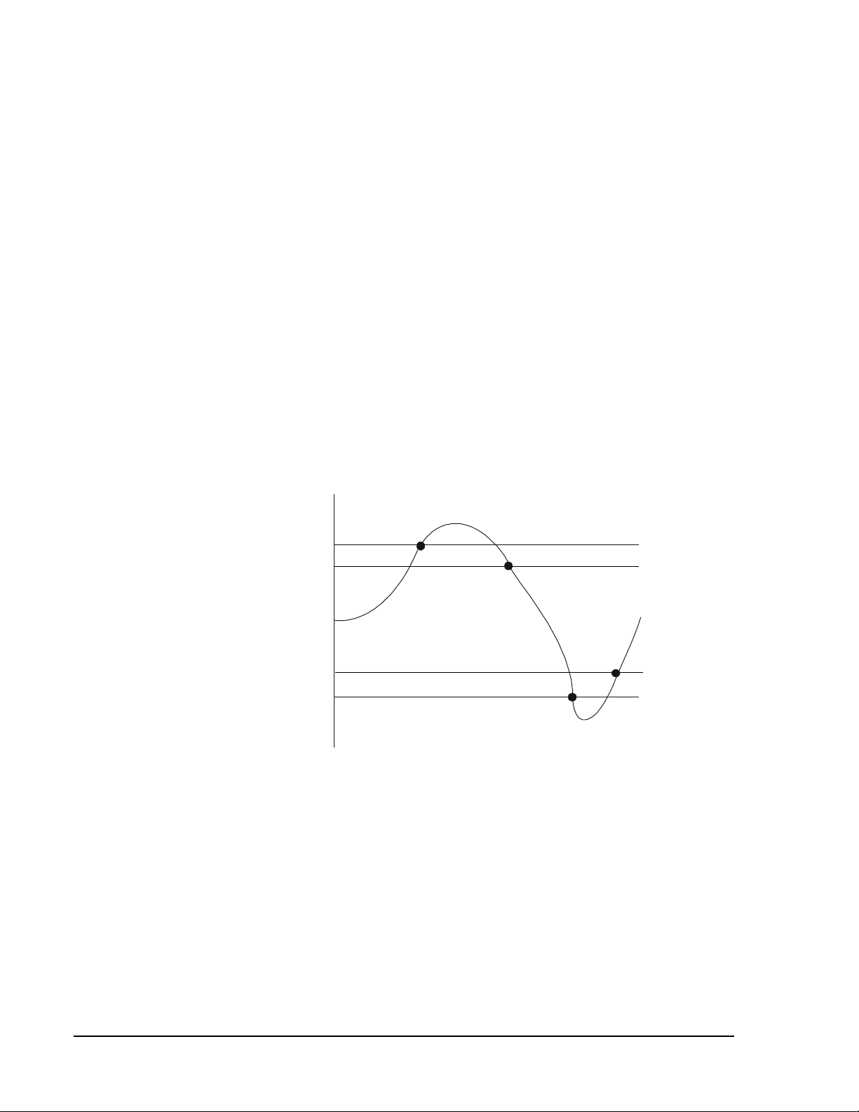
The high limit and the low limit define at which levels the analog input
reading will generate an alarm, either for remote monitoring or for internal
use within the control sequences in the DX-9100. A limit differential
defines when a point comes out of alarm.
Note: The limits cannot be deleted. If you do not want alarms, enter
limits beyond the high/low range of the sensor.
AI
Val ue
High Limit
Low Limit
No Alarm
High Alarm
Low Alarm
No Alarm
Differential
Differential
dxcon005
Figure 5: How Alarm Limits Function
Via the GX Tool
Select AIn. Then select Data in the module menu. At the respective field,
enter the required value:
High Limit =
Low Limit =
Limit Differential =
AI: Alarm Limits

Configuration Guides—DX-9100 Configuration Guide
23
The low limit and high limit alarm processing can be disabled. In the menu
bar, select Edit-Add Alarm Disable. The corresponding module (box) will
appear on screen. Make connections as described earlier under
Configuration Tools - Making Connections.
Note: The Alarm Disable feature is sometimes referred to as Auto
Shutdown in the BAS.
Via the SX Tool
Under Analog Inputs, the alarm limits differential is adjustable with Item
ADFn (RI.06). The high limit is at Item HIAn (RI.03), the low limit is at
Item LOAn (RI.04).
The low and high limit alarm processing can be disabled by making a
logical connection to Item ALD@ - Alarm Disable Condition Source
(General Module RI.31).
For Both SX and GX
When the logic signal connected to ALD@ or Alarm Disable Condition
Source is true (1), alarm states on analog inputs will be frozen until the
logical signal returns to false (0). (Alarm states on analog inputs to XT
modules are not frozen by the ALD@ connection.)
The Filter Time Constant Ts (seconds) is used to filter out any cyclic
instability in the analog input signals. The calculations are:
FV
t
= FV
t-1
+ [1/(1 + T
s
)] * (AI
t
- FV
t-1
)
Where: FV
t
= Filtered Analog Value at current time
FV
t-1
= Filtered Analog Value at previous poll
AI
t
= Actual Analog Value at current time
Via the GX Tool
Select AIn. Then select Data in the module menu. At the Filter Constant
(sec) field, enter a number within the recommended range 0 to 10.
Via the SX Tool
Under Analog Inputs, the Filter Time Constant is selected at Item FTCn
(RI.05).
1. You can read the AI values, and read and modify the alarm limit
values using the DX front panel. See Display Panel and Keypads in
the DX-9100 Extended Digital Controller Technical Bulletin
(LIT-6364020) in FAN 636.4 or 1628.4.
AI: Filter Time
Constant
AI Notes

24
Configuration Guides—DX-9100 Configuration Guide
2. The alarm condition of one or more analog inputs is also indicated by
an LED (AL) on the front panel. If the LED is steady, the current AI is
in alarm; if flashing, another AI is in alarm.
3. Using the SX Tool, analog input values can be read at Analog Inputs
Item AIn (RI.07), and the percent of range value can be read at Item
AI%n (RI.08). The value as an ADC count can be read at Item ADCn
(RI.09).
4. Using the SX Tool, analog input alarm statuses can be read at General
Module Item AIS (RI.07), or at Analog Input Item AISTn (RI.10),
where bits X1 and X2 indicate the high and low alarm conditions,
respectively.
5. Under Analog Inputs, the analog Item AISTn (RI.10), bits X3 and X4,
indicate an input over-range (input about 2% of range above HR)
condition and an input under-range (input about 2% of range below
LR) condition, respectively. (This information is available on the
SX Tool only.)
6. Calibration coefficients for active and passive analog inputs are stored
in the EEPROM of the DX. See the Calibration Values section further
in this document.
Source Points (Outputs)
AIn The current value of the analog input.
AI%n The current value of the analog input in percent (%) of range.
AIHn A 1 if the analog input is above its high limit and not below the
high limit - limit differential.
AILn A 1 if the analog input is below the low limit and not above the
low limit + limit differential.
OVRn A 1 when the value of an active analog input is more than
about 2% above its high range (overrange condition), or a
passive analog input is open circuited.
UNRn A 1 when the value of an active analog input is more than
about 2% below its low range (underrange condition), or a
passive analog input is short circuited.
Destination Points (Inputs)
None.
Note: The following destination point is applicable to all analog inputs:
ALDS@ The connection to disable alarm processing on analog inputs
AI1 - AI8.
GX Labels
Configuration Guides—DX-9100 Configuration Guide
25
The DX-9100 Controller can accept up to eight digital inputs, which will
be considered active when driven to a common digital ground by an
external volt-free contact. The DI is defined and configured by the
following parameters:
•
User Name and Description (GX only)
•
Prescaler
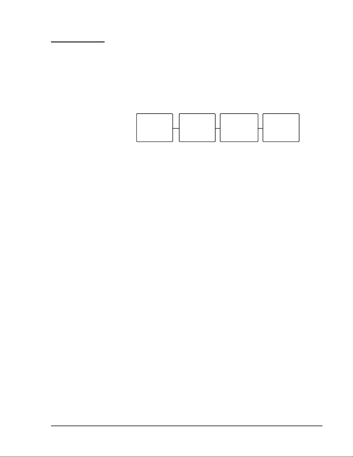
The digital input transitions are counted as follows:
Pulse
Counter
CNTRn
Count
Transition
DICn
Prescale
Factor
PCn
Digital
Input
DIn
dxcon006
Figure 6: Digital Input Transitions
The Pulse Counter (CNTRn) counts all state transitions of the bit-Item
DICn. A state transition at DICn occurs when the number of transitions
from 1 to 0 of DIn Digital Input equals the value of the Prescaler Factor
(PCn). For example, if PCn is equal to 1, then every 1 to 0 state transition
at the DI will add 1 to CNTRn. If equal to 3, then three changes from 1 to
0 will add 1 to CNTRn. The maximum transition rate of DIn is 10 pulses
per second (minimum 50 ms On and 50 ms Off).
Via the GX Tool
Select DIn. Then select Data in the module menu.
At the User Name field, enter the name, which can have a maximum of
eight characters.
At the Description field, enter the descriptive text, which can have a
maximum of 24 characters.
At the Prescaler (counts) field, enter a number between 1 and 255.
Via the SX Tool
Under General Module, enter the prescaler for each digital input at Items
PC1 (RI.22) to PC8 (RI.29).
1.
You can read the DI’s status and counter values using the DX front
panel. See Display Panel and Keypads in the DX-9100 Extended
Digital Controller Technical Bulletin (LIT-6364020) in FAN 636.4
or 1628.4.
2. On the SX Tool, the digital input status (DIn), the count transition
status (DICn) and the pulse counter values can be read under General
Module at the Items given in Figure 6.
Digital Input
Configuration
DI: User Name,
Description,
Prescaler
DI Notes

26
Configuration Guides—DX-9100 Configuration Guide
Source Points (Outputs)
DIn The current status of the digital input.
DICn Toggles from 0 to 1 or 1 to 0 when the number of digital input
transitions (counts) equals the prescaler.
Destination Points (Inputs)
None.
The DX-9100 Controller has two analog outputs (numbered 1 and 2),
controlled by two analog output modules, and six digital (triac) outputs
(numbered 3 to 8) controlled by six logic output modules.
Versions 2 and 3 of the DX-9100 have an additional six analog outputs
(numbered 9 to 14) controlled by six analog output modules.
The analog output module provides the interface between a 0-10 VDC or
0/4-20 mA hardware output and a numeric value scaled to a 0-100% range
using a high and low range variable.
Each analog output is defined and configured by the following parameters:
•
user name and description (GX Only)
•
type of output
•
numeric source
•
increase/decrease source (if any)
•
low and high ranges
•
forcing mode and level
•
hold or auto on power up
•
output limits, enable limits
Via the GX Tool
Select AOn. Then select Data in the module menu. At the field
User Name, enter the name.
At the Description field, enter the description.
Then enter the output code:
0 = Disabled
1 = 0 to 10 VDC
2 = 0 to 20 mA (not available for Outputs 11-14)
3 = 4 to 20 mA (not available for Output 11-14)
GX Labels
Analog Output
Configuration
AO: Output Type

Configuration Guides—DX-9100 Configuration Guide
27
Via the SX Tool
Under Output Modules, the output type can be configured in Item AOTn
(RI.00). To define the output signal set the bits as follows:
X2 X1 = 00 Output Disabled
X2 X1 = 01 Output 0-10 V
X2 X1 = 10 Output 0-20 mA (not available for Outputs 11-14)
X2 X1 = 11 Output 4-20 mA (not available for Outputs 11-14)
This defines the source of the numeric control signal that drives the output
module. The output module can, alternatively, have two logic sources: the
source of the increase signal and the source of the decrease signal. The rate
of increase or decrease is fixed at 1% per second.
Via the GX Tool
Expand both source and AOn modules. Place the mouse on the source
point. Hold down the left mouse button and drag the cursor to the center of
AO@. The connection will be made when the mouse button is released.
If logic variables (Increase/Decrease) are used as a source to drive the
analog output, then the source module and AOn module must be expanded
as described above. Place the cursor on the logic source point. Press the
mouse button and while keeping it pressed, drag the cursor to INC@ in the
AOn module. Release the mouse button to make the connection. Repeat
the same procedure for the DEC@ connection.
Via the SX Tool
Under Output Modules, Item AO@n (RI.01) defines the source of the
numeric control signal. Alternatively, the source of the increase signal is
defined in Item INC@n (RI.10), and the source of the decrease signal is
defined in Item DEC@n (RI.11).
This defines the source of a logic variable that forces the Analog Output to
a forcing level between 0 and 100%. When the logic source is 1, the AO
will be forced to the % entered in Forcing Level. When the logic source
is 0, the AO will be commanded to position via the source point.
Note: If a PID is connected to the AO and the AO is forced, the PID will
experience force-back, which means the PID is also in Hold mode
at this time and its output is forced to the value of the analog
output.
AO: Source
AO: Forcing
Mode and Level

28
Configuration Guides—DX-9100 Configuration Guide
Via the GX Tool
Select AOn. Then select Data in the module menu. At the
Forcing Level (%) = field, enter a number between 0 and 100%.
Double-click on AOn to expand the module. Double-click on the source
module. Place the cursor on the logic source point. Press the mouse button
and while keeping it pressed, drag the cursor to AOF@. Release the mouse
button to make the connection.
Via the SX Tool
Under Output Modules, Item AOF@n (RI.02) defines the source of a logic
variable that forces the output to the forcing level, which is defined in Item
OFLn (RI.05).
Upon power restoration, the AO can optionally be forced to a Hold
(Manual) or Auto (Hold reset) condition, irrespective of the Hold
condition before the power failure and overriding the Initialization on
Power Up setting for the controller and overrides sent from the front panel
or BAS.
Via the GX Tool
Select AIn. Then select Data in the module menu. Then enter 1 for the
appropriate power up condition, if required:
Hold on Power Up = (1 = Yes)
Auto on Power Up = (1= Yes)
If both Hold and Auto are enabled, Hold has higher priority. If both are
disabled, the current setting under the Initialization on Power Up field
determines the output.
Via the SX Tool
Under Output Modules, set bits X7 and X8 of Item AOTn (RI.00) as
follows:
bit X8 = 0 The Hold mode is not altered after a power failure.
bit X8 = 1 The Hold mode is set at power up to the status set in bit X7.
bit X7 = 0 The Hold mode is set to hold at power up if bit X8 is set.
bit X7 = 1 The Hold mode is reset (set to 0) at power up if bit X8 is set.
AO: Hold or Auto
On Power Up

Configuration Guides—DX-9100 Configuration Guide
29
The High Range Item (HRO) defines the level of the control source signal
(AOn), which would correspond to an output of 100%.
The Low Range Item (LRO) defines the level of the control source signal
(AOn), which would correspond to an output of 0%.
If LROn < AOn < HROn OUTn = 100 * (AOn - LROn)/(HROn -
LROn)%
If AOn <= LROn OUTn = 0% (0 V, 0/4 mA)
If AOn >= HROn OUTn = 100% (10 V, 20 mA)
When the source point is equal to the high range, then the output will be at
the maximum signal (10 V/20 mA). When the source point is equal to low
range, then the output will be at the minimum signal (0V, 0/4 mA).
Via the GX Tool
Select AIn. Then select Data in the module menu. At the High Range and
Low Range fields, enter the appropriate numbers within the range of the
source signal:
High Range =
Low Range =
Via the SX Tool
Under Output Modules, set the High Range at Item HROn (RI.03) and the
Low Range at Item LRO (RI.04).
The output high limit defines the maximum output in percent. The output
low limit defines the minimum output in percent. These limits are enabled
by a logic connection and are only operative when the logic source is at 1.
When the limits are enabled:
If OUTn > HLOn
OUTn = HLOn
If OUTn < LLOn
OUTn = LLOn
AO: Range
AO: Output
Limits, Enable
Limits

30
Configuration Guides—DX-9100 Configuration Guide
Via the GX Tool
Select AOn. Then select Data in the module menu. At the
High Limit % and Low Limit % fields, enter the desired number (0-100%).
For Enable Limits, expand both source and AOn modules. Position the
cursor on the source point. Press the mouse button, and while keeping it
pressed, drag the cursor to ENL@. Release the mouse button to make the
connection.
Via the SX Tool
Under Output Modules, set the following:
High Limit on Output = Item HLOn (RI.08)
Low Limit on Output = Item LLOn (RI.09)
The limits are enabled by a logic connection to Item ENL@n (RI.12).
1. The AO can be read and overridden (placed in hold) from the DX
front panel. See Display Panel and Keypads in the DX-9100 Extended
Digital Controller Technical Bulletin (LIT-6364020) in FAN 636.4 or
1628.4.
2. On the SX Tool, the analog output values can be read in percent at
Item OUTn (RI.06) and can be modified when the module is in Hold
mode.
3. On the SX Tool, Analog output control and status can be seen at
Item AOCn (RI.07) in the following bits:
X1 = 1 OUHn Output in Hold mode (Manual)
X2 = 1 AOHn Output at High Limit ... 100%
X3 = 1 AOLn Output at Low Limit ... 0%
X4 = 1 AOFn Output is Forced
X6 = 1 OULn Output is Locked (Both INC@n and DEC@n
are true)
4. The analog output module can be set in Hold on the DX front panel or
by the PLC, the SX Tool, a BAS, or by configuration on power up.
AO Notes
Loading...