


14-104-0,Rev.A
Product/Technical Bulletin
Issue Date March 2016
T-3100, T-3200, and T-3300 Series Controllers
The T-3100 and T-3300 Series proportional action pneumatic thermostats are designed to maintain temperature in accordance with the return air temperature in terminal air conditioning units. The T-3200 Series of pneumatic thermostats are designed to control pneumatic actuators in single temperature, dual pressure applications.
The T-3111 and T-3311 Series controllers are combination pneumatic thermostats and valve actuators. The T-3111 provides proportional control of a steam or water valve on a single temperature application, while the T-3311 provides control in
dual temperature, dual pressure applications.
WARM
Figure 1: T-3100 Remote Mounted Thermostat and
T-3311 Valve Top Thermostat
Features and Benefits
Models are Available in |
Allows seasonal change over from cooling to |
Direct-reverse Acting or |
heating or heating to cooling automatically |
Reverse-direct Acting |
|
Direct or Reverse Acting |
Suits heating or cooling applications |
Models Available with Liquid |
|
Filled Temperature |
|
Measuring Elements |
|
Models Available with an |
Field adjustable or concealed to maintain system |
External or Concealed |
design as commissioned |
Setpoint Adjusting Screw |
|
Valve Top Models |
The T-3111 and T-3311 are direct replacements |
Compatible with |
for the T-3110 and T-3310 Series Valve Top |
VG7000 Series Valves |
Actuators |
© 2016 Johnson Controls, Inc. |
1 |
Part No. 14-1104-0, Rev. A
Code No. LIT-7171156

Ordering Information
Table 1: Ordering Information
Code |
Action |
Element |
Setpoint |
Mounting |
Application |
|
Number |
(Proportional) |
Adjustment |
||||
T-3100-2 |
Direct Acting |
Bulb |
External |
Remote |
Single Temperature |
|
T-3100-3 |
Reverse Acting |
|
|
|
|
|
|
|
|
|
|
|
|
T-3111-1 |
Direct Acting |
|
|
|
|
|
|
|
|
|
|
|
|
T-3111-2 |
Reverse Acting |
Bulb |
External |
|
|
|
T-3111-3 |
Direct Acting |
Averaging |
External |
Valve Top |
Single Pressure |
|
T-3111-6 |
Direct Acting |
|
Concealed |
|
|
|
|
|
|
|
|
|
|
T-3200-1 |
DIR at 15 and 20 psig |
Averaging |
Concealed |
Remote |
Single Temperature |
|
(103/138 kPa) |
Dual Pressure |
|||||
|
|
|
|
|||
|
|
|
|
|
|
|
T-3300-1 |
DIR at 15 psig |
|
|
|
|
|
(103 kPa) |
|
|
|
|
||
|
REV at 20 psig |
Bulb |
External |
Remote |
|
|
|
(138 kPa) |
Dual Temperature |
||||
|
|
|
|
|||
|
|
|
|
|
|
|
T-3300-2 |
DIR at 20 psig |
|
|
|
|
|
(138 kPa) |
|
|
|
Dual Pressure |
||
|
REV at 15 psig |
|
|
|
|
|
|
(103 kPa) |
|
|
|
|
|
|
|
|
|
|
|
|
T-3311-1 |
DIR at 15 psig |
|
|
|
|
|
(103 kPa) |
|
|
|
|
||
|
REV at 20 psig |
|
|
|
|
|
|
(138 kPa) |
Bulb |
External |
Valve Top |
Dual Temperature |
|
|
|
|
|
|
|
|
T-3311-2 |
DIR at 20 psig |
|
|
|
|
|
(138 kPa) |
|
|
|
Dual Pressure |
||
|
REV at 15 psig |
|
|
|
|
|
|
(103 kPa) |
|
|
|
|
|
|
|
|
|
|
|
2 T-3100, T-3200, and T-3300 Series Controllers Product/Technical Bulletin

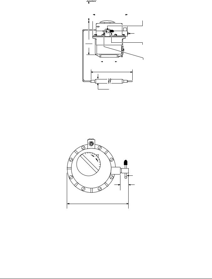
Dimensions
|
|
|
Extends to maximum |
5-1/8 |
Subordinate |
|
|
|
|
130 |
Connection 1/8 inch |
|
|
3-3/8 |
4-3/4 |
|
|
|
|
|
NPT, Internal Thread |
||
|
5/8 |
86 |
121 |
|
|
|
|
|
|
|
|
|
16 |
|
|
|
Supply Air to |
|
|
|
|
|
|
|
|
|
|
|
Restrictor |
3/4 |
1/4 |
|
|
|
Branch |
|
|
|
Restrictor |
||
19 |
6 |
|
|
|
|
|
4-3/4 |
|
Branch |
||
|
|
|
|
||
3 |
|
|
|
Marked |
|
|
|
121 |
|
||
76 1-1/2 |
|
|
|
|
|
|
|
|
|
|
|
38 |
|
|
|
|
|
|
1/4 |
|
|
|
Control Air |
|
|
|
|
3/4 |
|
|
6 |
|
|
|
|
|
|
|
|
|
19 |
|
|
|
|
5-11/16 |
|
|
Capillary Length |
42 |
|
144 |
8-11/16 |
|
1067 |
Extends to maximum |
|||
|
|
|
|
|
220 |
|
|
|
6-9/16 |
|
|
|
|
|
167 |
|
|
5/168 Diameter
Figure 2: Dimensions and Mounting Details for T-3100, in./mm
|
|
|
|
|
|
|
|
|
|
|
|
|
3-1/16 |
|
|
|
|
|
|
|
|||||
|
78 |
|
|
|
4-3/4 |
|
|
Barbed |
||||
|
|
|
|
|
|
|||||||
|
|
|
|
|
|
|
|
|
|
|
|
|
|
|
|
|
|
|
|
120 |
|
||||
|
|
|
|
|
|
|
|
|
Restrictor Tee |
|||
|
|
|
|
|
|
|
|
|
|
|
|
|
|
|
|
|
|
|
|
|
|
|
|
|
|
|
|
|
|
|
|
|
|
|
|
|
|
|
|
|
|
|
|
|
|
|
|
|
|
|
|
|
|
|
Subordinate |
|
|
|
Connection |
|
|
|
1/8 inch NPT, |
|
4-7/16 |
|
Internal Thread |
|
|
|
|
|
113 |
|
Sealing Cap |
|
18 |
|
(Open Branch) |
Capillary Length |
|
|
|
|
457 |
2-1/4 |
Supply Air Connection |
|
|
||
|
|
57 |
|
|
|
(Restrictor Branch) |
|
|
|
|
Averaging Element Length 243896
Figure 3: Concealed Adjustment for T-3111, in./mm
T-3100, T-3200, and T-3300 Series Controllers Product/Technical Bulletin 3
|
|
|
|
|
|
|
|
|
|
3- |
3/16 |
|
|
|
|
|
|||
80 |
|
|
4-3/4 |
|
Barbed |
||||
|
|
|
|||||||
|
|
|
|
|
|
|
|
|
|
|
|
|
|
|
121 |
|
Restrictor Tee |
||
|
|
|
|
|
|
|
|
|
|
|
|
|
|
|
|
|
|
|
|
|
|
|
|
|
|
|
|
|
|
|
Subordinate |
|
Connection |
|
1/8 inch NPT, |
4-9/16 |
Internal Thread |
|
|
116 |
Sealing Cap |
|
(Open Branch) |
Capillary Length |
42 |
|
|
2-1/4 |
|
Supply Air Connection |
1067 |
|
|
|
|||
|
|
57 |
||||
|
|
|
|
(Restrictor Branch) |
||
|
|
|
|
|
|
6-9/16
167
5/168 Diameter
Figure 4: Exposed Adjustment for T-3111, in./mm
|
OL |
O |
|
C |
|
<![endif]>W
A
R
M
Supply
Air
3/4
19
5-3/16
132
Figure 5: Mounting Details for T-3111, in./mm
4 T-3100, T-3200, and T-3300 Series Controllers Product/Technical Bulletin
4-3/4 |
to maximum |
5-1/8 |
121 |
130 |
|
|
|
|
|
Barbed Restrictor |
|
|
|
|
|
Tee Supply |
|
|
|
|
|
(Restrictor Branch) |
|
3-1/8 |
|
|
Marked |
|
|
|
|
|
||
|
|
79 |
|
|
|
|
5/8 |
|
|
|
Output |
|
|
|
|
(Open Branch) |
|
|
16 |
|
|
|
|
3/4 |
1/4 |
|
|
|
Switching Air |
19 |
6 |
|
5-1/2 |
|
Connection |
3 |
|
|
|
|
|
|
|
140 |
|
|
|
76 1-1/2 |
|
|
|
|
|
|
|
|
|
|
|
38 |
|
|
|
|
|
|
1/4 |
|
|
|
13/16 |
|
6 |
|
|
|
|
|
|
|
|
|
21 |
|
|
|
5-13/16 |
to maximum |
8-13/16 |
|
Capillary Length |
18 |
148 |
|
224 |
|
|
457 |
|
|
|
Averaging Element Length 243896
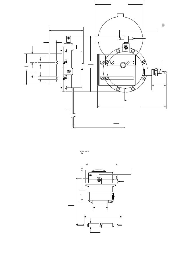
Figure 6: Dimensions and Mounting Details for T-3200, in./mm
|
|
|
|
|
|
|
|
Supply Air |
3-1/16 |
|
|
|
|||||
|
|
|
|
Straight Connector |
||||
78 |
|
4-3/4 |
|
|||||
|
|
for 1/4 inch O.D. |
||||||
|
|
|
|
|
|
|
|
|
|
|
|
|
121 |
||||
|
|
|
|
|
Polyethylene Tubing |
|||
|
|
|
|
|
|
|
|
|
|
|
|
|
|
|
|
|
|
|
|
|
|
|
|
|
|
|
Subordinate
Connection

 1/8 inch NPT, 4-9/16 Internal Thread
116
Capillary Length |
42 |
2-1/4 |
|
1067 |
57 |
|
|
6-9/16
167
5/168 Diameter
Figure 7: Exposed Dimensions for T-3311, in./mm
T-3100, T-3200, and T-3300 Series Controllers Product/Technical Bulletin 5
 Loading...