


 Loading...
A421 Series Standard Electronic
Temperature Controls Installation Guide
Applications
Important: Use this A421 Series Electronic Temperature Control only as an operating control. Where failure or malfunction of the A421 Control could lead to personal injury or property damage to the controlled equipment or other property, additional precautions must be designed into the control system. Incorporate and maintain other devices, such as supervisory or alarm systems or safety or limit controls, intended to warn of or protect against failure or malfunction of the A421 Control.
Important: Utiliser ce A421 Series Electronic Temperature Control uniquement en tant que dispositif de régulation. Lorsqu'une défaillance ou un dysfonctionnement du A421 Control risque de provoquer des blessures ou d'endommager l'équipement contrôlé ou un autre équipement, la conception du système de contrôle doit intégrer des dispositifs de protection supplémentaires. Veiller dans ce cas à intégrer de façon permanente d'autres dispositifs, tels que des systèmes de supervision ou d'alarme, ou des dispositifs de sécurité ou de limitation, ayant une fonction d'avertissement ou de protection en cas de défaillance ou de dysfonctionnement du A421 Control.
The A421 Series Electronic Temperature Controls are single-stage, electronic temperature controls with a single-pole, double-throw (SPDT) output relay.
A421 Controls feature a backlit LCD with adjustable brightness and three-button touchpad interface that you can set up to restrict user adjustments. An LED indicates the output relay's on and off status.
A421 Controls have simple on and off temperature settings for heating or cooling, an adjustable anti-short cycle delay, temperature setback, and sensor offset capability. The temperature control range is -40°F to 212°F or -40°C to 100°C.
The A421 Controls are available either in Type 1 (NEMA), IP20 (CE), high-impact plastic enclosures suitable for surface or DIN rail mounting (Figure 1), or in Type 4X (NEMA), IP66 (CE) watertight, corrosion resistant surface mount enclosures (Figure 2).
Part No. 24-7664-3019 Rev E 2018-11-13
A421ABC-x, A421AEC-x, A421GBF-x, A421GEF-x

Dimensions
Figure 1: A421 Control with Type 1 (NEMA), IP20 enclosure dimensions, in. (mm)
Figure 2: A421 Control with Type 4X (NEMA), IP66 enclosure dimensions, in. (mm)
Parts included
Each A421 Control includes a Johnson Controls® or PENN® A99 Series temperature sensor. See A99 Series Temperature Sensors, Wiring, and Technical specifications for more information about A99 sensors.
2 A421 Series Standard Electronic Temperature Controls Installation Guide

A99 Series Temperature Sensors
The A421 Controls require an A99 sensor, and each A421 Control includes an A99 sensor. Any A99 Series sensor works with the A421 Series Controls. Do not replace an A99 Series sensor with any other brand, series, or type of temperature sensor. See Ordering information for available A99 Series sensor models.
You can extend the sensor leads in the field. See Table 1 for information about wire sizes and lengths. On long sensor cable runs, use shielded cable to reduce electromagnetic interference (EMI). Observe EMI best practices when you route sensor leads.
Do not immerse the A99 Series sensors in water or any other liquid. The A99 sensors are moisture tolerant and splash resistant but if you immerse the sensor, liquid can enter the sensor probe where the steel tube meets the wire cable and result in sensor failure, which voids any warranty.
In applications where the sensor may be exposed to a lot of moisture, splashing, or rain, mount the sensor in a vertical position with the cable at the bottom routed downward so that moisture can drain away from the stainless steel probe. Use a suitable bulb well for complete fluid immersion applications. See Ordering information for information about bulb wells.
The A99 Series sensors are positive temperature coefficient (PTC) sensors. To test an A99 sensor, disconnect the sensor from the control and measure the resistance between the sensor leads in the following situations:
•When the temperature at the sensor is 77°F (25°C), the resistance should be 1,035 ohms.
•When the temperature at the sensor is 32°F (0°C), the resistance should be 855 ohms. See Troubleshooting for more information.
When you connect an A99 sensor to a standard A421 Control, the control restricts the range of usable values from -40°F to 212°F or -40°C to 100°C.
See Wiring, Technical specifications, and refer to the A99B Series Temperature Sensors Product/ Technical Bulletin (LIT-125186) for more information about A99 Series sensors.
Mounting
Observe the following guidelines when you locate and mount an A421 Control:
•Make sure that the mounting surface can support the control, DIN rail, mounting hardware, and any user-supplied panel or enclosure.
•Mount the control in a vertical, upright orientation wherever possible. It is best practice to use DIN rail mounting for type 1 controls.
•In direct-mount applications, mount the control on a flat and even surface.
Mount the control in a location free of corrosive vapors and observe the ambient operating conditions listed in Technical specifications for the A421 Control and the A99 sensor.
•Allow sufficient space to connect and route wires, view the LCD, and use the touchpad.
•Do not mount the control on surfaces that are prone to vibration or in a location where highvoltage relays, motor starters, other sources of electromagnetic emissions, or strong radio frequency may cause interference.
•Do not install the control in an airtight enclosure.
•Do not install heat generating devices with the control in an enclosure that may cause the ambient temperature to exceed 150°F (66°C).
A421 Series Standard Electronic Temperature Controls Installation Guide |
3 |

Mounting a Type 1/IP20 control on DIN rail
1.Provide a section of 35 mm DIN rail that is longer than the control width. Mount the DIN rail in a suitable location and use appropriate mounting hardware.
2.Clip the control module on the rail, position the module’s upper DIN rail clips on the top rail, and gently snap the lower clips on to the bottom of the rail.
Direct-mounting a Type 1/IP20 control to a wall or other flat surface using the four keyhole slots
1.Disconnect the power and remove the enclosure cover. Place the control vertically against the wall surface in a suitable location, and mark the keyhole slot locations on the mounting surface.
2.Install appropriate screws or fasteners and leave the screw heads approximately one or two turns away from flush to the mounting surface.
3.Position the control mounting slots over the screw heads, and then tighten the mounting screws to secure the control to the surface.
Note: When you mount the control on an uneven surface, use shims to mount the control evenly.
Additional guidelines for mounting Type 4X/IP66 controls
You can mount the Type 4X models to flat vertical surfaces using the four holes at the enclosure corners. Place the control against a flat wall surface in a suitable location, and mark the mounting screw hole locations on the mounting surface. Use appropriate screws and shims to mount the control evenly on the surface.
On Type 4X models, select the knockout for removal. Place a screwdriver blade on the knockout near the edge. Apply a sharp blow to the screwdriver handle to loosen the knockout. Be careful not to damage the control’s interior components.
The A421 Control's temperature setback (BI) function requires an additional low-voltage, two-wire cable for operation. On Type 4X/IP66 enclosures, you must install a suitable watertight fitting in an available knockout to pass the two-wire cable through the enclosure wall.
You can rotate the control enclosure base on the Type 4X/IP66 models 180º relative to the control enclosure cover and LCD, to bring the electrical connection to the top or bottom of the mounted control.
Note: Do not twist the wiring harness between the enclosure base and cover more than 180º.
4 A421 Series Standard Electronic Temperature Controls Installation Guide

Wiring
 WARNING
Risk of Electric Shock
Disconnect or isolate all power supplies before making electrical connections. More than one disconnection or isolation may be required to completely de-energize equipment. Contact with components carrying hazardous voltage can cause electric shock and may result in severe personal injury or death.
 Avertissement
Risque de décharge électrique
Débrancher ou isoler toute alimentation avant de réaliser un raccordement électrique. Plusieurs isolations et débranchements sont peut-être nécessaires pour -couper entièrement l'alimentation de l'équipement. Tout contact avec des composants porteurs de tensions dangereuses risque d'entraîner une décharge électrique et de provoquer des blessures graves, voire mortelles.
Important: Use copper conductors only. Make all wiring in accordance with local, national, and regional regulations.
Important: Do not exceed the A421 Control’s electrical ratings. Exceeding the electrical ratings can result in permanent damage to the control and void any warranty.
Important: Run all low-voltage wiring and cables separate from all high-voltage wiring. It is best practice to use shielded cable for input (sensor) cables that are exposed to high electromagnetic or radio frequency noise.
Important: Electrostatic discharge (ESD) can damage A421 Controls. Use proper electrostatic discharge precautions during installation and servicing to avoid damaging A421 Controls.
Important: Do not connect supply power to the A421 Controls before checking all wire connections. Short circuits or improperly connected wires can result in damage to the modules and void any warranty.
Important: When you connect an A99 sensor with a shielded cable to an A421 Control, connect the cable shield drain lead to the common (COM) terminal on the sensor and binary input terminal block (TB3). Do not connect the shield at any other point along the cable, and isolate and insulate the shield along the entire length of the sensor cable. If you connect a cable shield at more than one point, transient currents can flow through the sensor cable shield and cause erratic control operation.
Observe the wire size restrictions listed in Table 2 and the electrical ratings listed in Technical specifications.
Observe the following guidelines, procedures, and illustrations when you wire an A421 Series Control and A99 Series sensor.
•Select the appropriate A99 sensors for the ambient operating range that the A421 Control monitors and controls, as shown in Table 7. See Technical specifications for more information.
•Keep the sensor leads as short as possible in your application. The additional resistance in long
A421 Series Standard Electronic Temperature Controls Installation Guide |
5 |
sensor cables creates an offset between the actual temperature and the displayed temperature. See Table 1 when you extend sensor leads.
•A99 sensors are not polarity specific. You can connect either lead to the SEN or COM terminals.
•It is best practice to use 22 AWG, stranded, twisted-pair cable with a shield to extend sensor cable runs.
Table 1: Maximum sensor cable lengths and wire sizes
Wire gauge |
Maximum sensor cable length1 |
|
|
16 AWG |
500 ft (150 m) |
|
|
18 AWG |
300 ft (100 m) |
|
|
20 AWG |
200 ft (60 m) |
|
|
22 AWG |
125 ft (40 m) |
|
|
1The maximum sensor cable lengths have less than 1°F (0.6°C) error between the temperature sensed at the A99 sensor and the temperature displayed on the LCD.
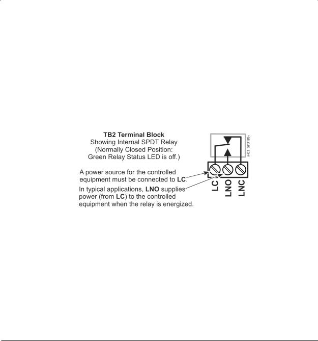
TB2 Terminal Block and SPDT relay output
The terminals LC, LNO, and LNC on the TB2 terminal block connect to an SPDT dry-contact relay in the A421 Control (Figure 3). The control does not provide any internal power to the TB2 terminals or relay contacts. The A421 Control energizes and de-energizes the relay to open and close the contacts based on the On/OFF temperature values.
•Relay De-energized (Off) = LC open to LNO as shown in Figure 3, and the relay status LED is off
•Relay Energized (On) = LC closed to LNO and the relay status LED is on
Figure 3: TB2 Terminal Block showing connections to the internal SPDT relay
Figure 4 shows how to wire the A421 Control to use the same power source that powers the controlled equipment to also power the A421 Control.
You can also provide an independent power source for the A421 Control on the TB1 terminals and then wire the TB2 relay terminals to a separate power source to switch and power the controlled equipment circuit.
6 A421 Series Standard Electronic Temperature Controls Installation Guide

Figure 4: Wiring the A421 Series Controls using the same power source to power the control operation and power the controlled equipment
Table 2: A421 Control wiring terminals and wire size information |
|
|||
|
|
|
|
|
Terminal |
Label |
Description, function, and requirements |
Wire sizes |
|
block |
|
|
|
|
TB1 |
LN |
Low-voltage 24 VAC control power (common): Connect the |
28 AWG to |
|
24 VAC |
|
24 VAC supply power to operate the control. |
12 AWG |
|
Models |
|
|
||
24 V |
Low-voltage 24 VAC control power (hot): Connect 24 VAC |
|||
|
0.08 mm² to |
|||
|
|
supply power to operate the control (via jumper from LC in |
||
|
|
Figure 4). |
4.0 mm² |
|
|
|
|
||
|
|
|
|
|
TB1 |
LN |
Line-voltage power source (common): Connect the neutral |
28 AWG to |
|
120/240 |
|
wire for 120 VAC supply power applications. Connect the |
12 AWG |
|
VAC |
|
L1 supply power lead for all 208/240 VAC supply power |
||
Models |
|
|
||
|
applications. |
0.08 mm² to |
||
|
|
|||
|
120 V |
Line-voltage 120 VAC control power (hot): Connect the |
4.0 mm² |
|
|
|
120 VAC supply power (hot) for 120 VAC supply power |
||
|
|
|
||
|
|
applications through the jumper from LC. (Figure 4). |
|
|
|
|
|
|
|
|
240 V |
Line-voltage 240 VAC control power (L2) terminal: Connect |
|
|
|
|
the L2 supply power connection for 208/240 VAC supply |
|
|
|
|
power applications through the jumper from LC. (Figure 4). |
|
|
|
|
|
|
|
TB2 |
LC |
Line-voltage SPDT relay common contact: Connects power |
28 AWG to |
|
|
|
supply to power the controlled load. Connect 24 VAC |
12 AWG |
|
|
|
(hot) for 24 VAC applications; 120 VAC (hot) for 120 VAC |
||
|
|
|
||
|
|
applications’ and L2 for 208/240 VAC applications. |
0.08 mm² to |
|
|
|
|
|
|
|
LNO |
Line-voltage SPDT relay normally open contact: Connects |
4.0 mm² |
|
|
|
controlled equipment to the line-voltage normally open |
||
|
|
|
||
|
|
(LNO) contact on the SPDT relay. When LC is closed to |
|
|
|
|
LNO, the relay is energized and the green LED is on. The |
|
|
|
|
LNO terminal typically provides power to the controlled |
|
|
|
|
equipment in cooling and heating applications. |
|
|
|
|
|
|
|
A421 Series Standard Electronic Temperature Controls Installation Guide |
7 |

Table 2: A421 Control wiring terminals and wire size information |
|
||
|
|
|
|
Terminal |
Label |
Description, function, and requirements |
Wire sizes |
block |
|
|
|
|
LNC |
Line-voltage SPDT relay normally closed contact: Connects |
|
|
|
controlled equipment to the line-voltage normally closed |
|
|
|
(LNC) contact on the SPDT relay. When LC is closed to LNC, |
|
|
|
the relay is de-energized and the green LED is off. The LNC |
|
|
|
terminal is not typically wired to the controlled equipment. |
|
|
|
|
|
TB3 |
BIN |
Detects a switch closure between the BIN and COM |
22 AWG (0.34 |
|
|
terminals and enables the selected temperature setback |
mm²) stranded, |
|
|
(tSb) value. |
shielded cable |
|
|
|
|
|
COM |
Connects the low-voltage common from the sensor and |
|
|
|
binary input. |
|
|
|
|
|
|
SEN |
Connects the low-voltage input signal wire from control |
|
|
|
sensors. |
|
|
|
|
|
Replacing an A419 Control with an A421 Control: Terminal locations and labels
The A421 Series Electronic Temperature Controls are the next generation of the A419 Series Electronic Temperature Controls.
If you need to replace an A419 Control with an A421 Control, be sure to note that wiring terminals on the TB1 and TB2 terminal blocks on A421 Controls are in different positions and have different terminal labels from the wiring terminals on the A419 Controls. Table 3 provides a cross-reference for matching the terminal labels on A419 Controls to the terminal labels on A421 Controls.
Note: The low-voltage signal terminals on the TB3 terminal block are labeled the same on both A419 Controls and A421 Controls.
See Figure 4 for terminal block and terminal positions on the A421 Control.
Table 3: A419 and A421 wiring terminal labels
Terminal block |
A419 Terminal label |
A421 Terminal label |
|
TB1 |
T1 |
LN |
|
(24 VAC) |
|
|
|
T2 |
24V |
||
|
|||
|
|
|
|
TB1 |
120 |
120V |
|
(120/240 VAC) |
|
|
|
240 |
240V |
||
|
|||
|
AC COM |
LN |
|
|
|
|
|
TB2 |
C |
LC |
|
(All Voltages) |
|
|
|
NO |
LNO |
||
|
|||
|
NC |
LNC |
Setup and adjustments
The front panel of the A421 Series Electronic Temperature Control has an LCD and a three-button UI (Figure 5).
8 A421 Series Standard Electronic Temperature Controls Installation Guide
Loading...