

Page 1

SeedStar
™
2 and SeedStar
™
Quick Reference Guide
XP Planter
A93891_19_17MAY12.indd 1 5/17/2012 8:19:41 AM
Page 2

SeedStar TM2
SeedStar TM2
Planter Quick Reference Guide
Planter Quick Reference Guide
With Optional
RowCommand
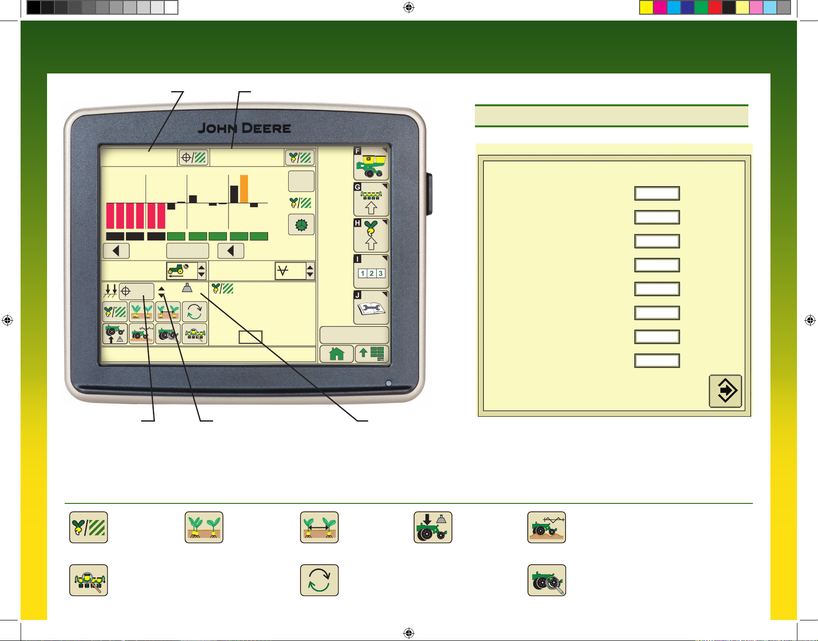
Drive Status Bars
Green Bars: Section
active and ready to plant.
Black Bars: Section
deactivated manually by
operator.
Outlined Bars:
Section deactivated by
SwathControlTM command
(when activated).
Bars Not Visible:
Section active, but cannot
be controlled manually or
with RowCommandTM.
RowCommandTM
Buttons: Select buttons
to turn sections on and off
manually.
Target Pneumatic
Down Force Level
Select button to view
Pneumatic Down Force
Control Panel
Pneumatic Down Force
System Indicator Arrows
Up arrow indicates system
is increasing down force
level.
Down arrow indicates
system is decreasing
down force level
TM
Planter At a Glance
Black bars indicate row is planting normally.
Orange bars indicate row is planting above or
below alarm setpoints.
Red bars indicate row is not planting.
32000
4 8 12 16 20
Enable All
Sections
5.4
(mph)
30
5.5
(mph)
40.0
(ac)
HI warn row #16
Speed Display Caution Message
Display
33 (lbs)
2
Population and Rates
Target Seeds per Area displays the desired seeding rate entered in Planter Rates Setup. On VRD machines,
(seeds/ac)
(seeds/ac)
select this button to toggle between programmed rates including prescriptions (Rate 6, VRD only).
Average Seeds per Area displays the actual average rate planted. Select button to toggle between whole
planter average and drive section average.
Other Useful
Buttons
Screens
Enter, Done,
Save, Finish
Drives Status ICON
Clutch Icon: Sections can only be controlled
manually by operator.
Section Icon: Sections are controlled by
John Deere Section ControlTM (when activated).
32300 32100
13.6
Row (seeds/ac)
Min: 11 27300
Max: 16 32900
Scan: 12 32200
4 0
User Defined
Totals
13.1
(In H2O)
Actual Pneumatic
Down Force Level
Toggle CancelToggle Home
Rotate Seed
Meters
QS
Reset
2:43 pm
Vacuum
Level Icon
QS
Reset
Quick Start
Reset
Getting Started
F
G
H
I
J
Planter – Main: Select for
planter main run screen.
Planter – Configuration:
Select to change planter frame,
drives, and sensor configuration.
Planter – Rates: Select to
change crop type, rates, and
meter configuration.
Totals: Select to view planted
area, hours, and calculators.
Diagnostics: Select to view
sensor readings and fault codes.
Pneumatic Down Force
Control Panel
147 (lbs)
145 (lbs)
Enter target down force in input box.
•
Select up or down arrow buttons to change
•
pneumatic down force by preset Step Value.
Enter low down force level alarm set point
•
and Step value in PDF Air Pressure Setup
Screen.
Select: Menu>>Planter>>Configuration
•
Softkey>>Sensor Tab>>Select PDF Air
Pressure from drop down menu.
A93891_19_17MAY12.indd 2 5/17/2012 8:19:43 AM
Page 3

Crop Setup
– Ground Drive
Crop Setup – Variable Rate Drive
Select Rates Softkey (H).
Select Crop Name from drop down menu. Select desired crop from list. If desired crop
name is not listed, select a Custom crop name.
Select Target Rate input box and enter desire population.
High and low warning limits are automatically set to a percentage above and below
target rate. To change limits, select High and Low Warning input boxes and enter a
new value.
Refer to Rate Charts & Settings Manual or Seed Transmission Sprocket Calculator
(Menu>>Planter>>Totals>>Calculator>>Seed Transmission).
To access Seed Estimators and Vacuum Calculator select Totals softkey (I) >> Calc tab
>> and choose the desired calculator from the drop down menu.
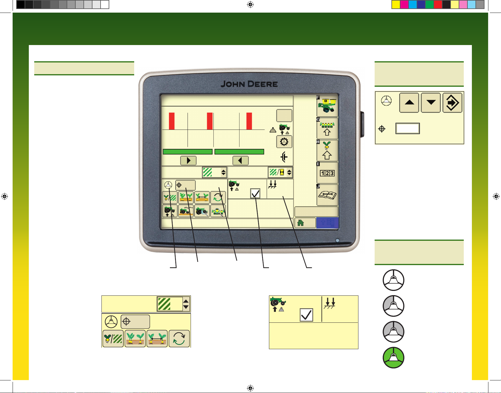
Standard Run Screen
Planter At a Glance
Black bars indicate row is planting normally.
Orange bars indicate
row is planting above
or below alarm setpoints.
Red bars indicate row
is not planting.
Drives Status Bar
Green bar indicates that
clutch or motor is engaged
and drives are active.
Gray bar indicates that clutch or motor is disengaged and drives are inactive.
Transport Mode:
To disable seed sensor warnings while in transport, navigate to: Planter >> Planter
Configuration >> depress “Transport Mode” key. To disable “Transport Mode” to
resume planting, depress key on screen.
Headland Warning Suppression:
Check box (Planter Configuration >> Sensor >> Seed) to disable seed sensor warnings
when the planter is raised in field position (requires a height sensor and height sensor
must be calibrated).
32000 32000
4 8 12
(seeds/ac)
Select Rates Softkey (H).
Select Use 1 Rate for All Motors check box. A check indicates one rate for all motors.
An empty box indicates different rates for each motor.
Rate 6 is used for map based prescription. To enable controller to use a prescription,
select the On drop down box under rate 6. From RUN screen select the Rx rate. Once rate
is selected, the run page has a small Rx indicator near the Target Seeds per Area icon.
Select Crop Name from drop down menu. Select desired crop from list. If desired crop
name is not listed, select a Custom crop name.
Select Disk Type drop down menu. If planter has mechanical meters, mechanical meter
selections appear. If planter has vacuum meters, vacuum disk selections appear.
Select meter or crop from list.
Select Seed Disk drop down menu and select the vacuum disk used. Verify this disk
is in meter.
Select Show Rates button, then select Change Rates button.
If using different rates for each motor, select Motor drop down menu to assign rates
to each motor.
Select Rate drop down menu and choose a rate from the list to assign a population
to that rate.
Select Target input box and enter the target population for the selected rate.
High and low warning limits are automatically set to a percentage above and below
target rate. To change limits, select High and Low Warning input boxes and enter a
new value.
To see a rate on the RUN page as a choice, select On and Off drop down box and
choose ON.
Select Enter button.
VRD Status
1.
No Activity Wheel Motion, Sensor Active
3.
Planter Lowered Drives Engaged
2.
4.
A93891_19_17MAY12.indd 3 5/17/2012 8:19:44 AM
Page 4
SeedStar TMXP
SeedStar TMXP
Target Seeds per Area Average Seeds per Area
Planter Quick Reference Guide
Planter Quick Reference Guide
Alarms and Limits Setup
32000
4 8 12
Enable All
Sections
5.4
(mph)
30
HI warn row #14
Target Pneumatic
Down Force Level
Select button to view Pneumatic
Down Force Control Panel
33 (lbs)
31600 32900
QS
Reset
+
%
-
13.6
Row (seeds/ac)
Min: 7 30900
Max: 14 36900
Scan: 14 36900
4 0
Pneumatic Down Force System
Indicator Arrows
Up arrow indicates system is
increasing down force level
Down arrow indicates system
is decreasing down force level
13.1
(In H2O)
2:43 pm
Actual Pneumatic
Down Force Level
Alarms and Limits Setup
Singulation Alarm 92 %
Seed Spacing CV Alarm 0.35
Ride Quality Alarm 90 %
Step Value 5 (lb)
Active PDF Pause Timer 5 sec
High Margin Alarm 131 (lb) + 75%
Target Margin 75 (lb)
Low Margin Alarm 37 (lb) - 50%
Alarms and Limits Setup Page:
Select and hold any SeedStar XP monitor navigation button for 4 seconds
to change alarm setpoints for that function. Enter “0” to disable alarm for
monitor function.
SeedStar XP Navigation Buttons
Seed Population
Select to view all SeedStar
XP monitor information on
one sceen.
Planter Details
A93891_19_17MAY12.indd 4 5/17/2012 8:19:45 AM
Seed Singulation Down Force
Seed Spacing
Scan
Select to scan SeedStar XP
run screens. Select and hold
to change scan settings.
Ride Dynamics
Select to view all monitored
information for a specific row.
Row Details
Page 5

Seed Population
Center line is target population. Bars above line
indicate rows planting above target. Bars below line
indicate rows planting below target. Bars turn orange
when above or below alarm setpoint. Bars turn red
when row is not planting (less than 2 seeds/second).
Select Menu>>Planter>>Rates Softkey to change
alarm setpoints.
Seed Population
4
8
12
%
QS
Reset
+
Row (seeds/ac)
Min: 7 31200
Max: 14 33500
-
Scan: 10 32100
4 0
Seed Singulation
Center line is perfect singulation (100%). Bars above
line indicate increasing percentage of multiples.
Bars below line indicate increasing percentage of
skips. Bars turn orange when nearing alarm setpoint.
Bars turn red when multiples or skip percentage
is above alarm setpoint. Change Singulation alarm
setpoint on Alarms and Limits Setup Page.
Seed Spacing Coefficient of Variation (CV)
Bottom of graph is perfect seed spacing (CV = 0).
Bars increase in height as seed spacing becomes
more variable. Bars turn orange when nearing alarm
setpoint. Bars turn red when seed spacing CV is
above alarm setpoint. Change Seed Spacing CV alarm
setpoint on Alarms and Limits Setup Page.
Down Force Margin
Center line is target down force margin. Bars above
line indicate rows with gauge wheel loads above
target margin. Bars below line indicate rows with
gauge wheel loads below target margin. Bars turn
orange when nearing alarm setpoint. Bars turn red
when down force margin is above alarm setpoint.
Change Down Force Margin target and alarm setpoint
on Alarms and Limits Setup Page.
Ride Dynamics
Top of graph is optimum ride quality (100%). Bottom of
graph is poorest ride quality (0%). Bars decrease in
height as row unit ride quality decreases. Bars turn
orange when nearing alarm setpoint. Bars turn red
when ride quality is below alarm setpoint. Change
Ride Quality alarm setpoint on Alarms and Limits
Setup Page.
4
Seed Singulation
4
Seed Spacing Coefficient of Variation (CV)
4
Down Force Margin
4
Ride Dynamics
8
8
8
8
12
12
12
12
QS
Reset
Singulation
Avg. 95 %
Skips High: 9
1 % 5 %
Multiples High: 14
3 % 21 %
QS
Reset
C
V
Seed Spacing CV
Avg. 0.18
Skips High: 4
1 % 5 %
Multiples High: 9
3 % 10 %
QS
Reset
(lbs)
+
-
Margin Low: 4 High: 9
65 35 102
Row %
Min: 4 85
Max: 9 100
Scan: 14 93
%
O
K
QS
Reset
Good Ride: 93
A93891_19_17MAY12.indd 5 5/17/2012 8:19:47 AM
Page 6
SeedStar TM
SeedStar TM
Pneumatic Down Force Quick Reference Guide
Pneumatic Down Force Quick Reference Guide
Active Down Force Pneumatic Down Force
This system automatically makes down
force adjustments based on target down
force margin and feedback from the gauge
wheel sensors. Data from the row unit gauge
wheel sensors is displayed as margin on the
monitor.
The operator selects a desired target margin
(the amount of extra down force applied to
the row unit, over and above what is required
for the opener disks to penetrate the soil and
achieve full planting depth). Active Down
Force automatically monitors the readings
from the gauge wheel down force sensors
and make pressure changes to the air spring
system to ensure the actual margin is equal
to the target margin. As field conditions
change the system automatically makes the
necessary pressure adjustments to maintain
target margin.
Target Margin:
The center line of the Down Force at
a Glance chart is the target margin.
Down Force at a Glance bars above the
center line indicate down force levels are
higher than desired. Bars below the center
line indicate down force levels are less
than desired.
ALL SEED RATES OFF
4 8 12
0.0
(ac)
70
The Height Sensor is not calibrated.
Active PDF
status
Target margin Actual margin
1
– – (lbs)
(lbs)
Margin Low High
– –,R – – –,R – –
(ac/h)
Active
PDF
+
-
0.0
Active system
on/off check box
QS
Reset
(lbs)
0
4:50 am
Actual down force in
air spring circuit
Margin Control Panel
75 0 (lbs)
Enter target margin in input box.
•
Select up or down arrow buttons
•
to change margin target by preset
Step Value.
Use default high and low margin
•
alarm values or enter custom values
as desired in Alarms and Limits
setup page.
Select:
•
From main run screen select
and hold any SeedStar XP monitor
navigation button for 4 seconds.
Active Down
Force Status
1. No Activity
Active Downforce input
screen. When the Active
Down Force Status icon
is shown, the system is
in active mode and margin
is displayed.
A93891_19_17MAY12.indd 6 5/17/2012 8:19:48 AM
70
0.0
(ac)
1
– – (lbs)
The Active Down Force
Margin run screen contains
the active on/off check box,
actual system down force,
the row with the lowest
margin, and the row with
the highest margin.
Active
PDF
(lbs)
Margin Low High
– –,R – – –,R – –
(lbs)
0
2. Sensor Diagnostic
Check OK
3. Wheel Motion
Sensor Active
4. Planter Lowered
(System Active
Page 7

Set-Point Down Force
Pneumatic Down Force
This system allows the operator to make
manual down force adjustments on the
display. Data from the air pressure sensor
located in the air tank valve block is
displayed as down force on the monitor.
The operator selects a desired target margin
(the amount of extra down force applied to
the row unit, over and above what is required
for the opener disks to penetrate the soil and
achieve full planting depth). The operator
then monitors the readings from the gauge
wheel down force sensors to determine
if down force changes are necessary to
ensure the actual margin is equal to the
target margin. As field conditions change,
margin should be monitored to determine if
down force adjustments should be made to
maintain target margin.
Target Margin:
The center line of the Down Force at
a Glance chart is the target margin.
Down Force at a Glance bars above the
center line indicate down force levels are
higher than desired. Bars below the center
line indicate down force levels are less
than desired.
The set-point Down Force
input screen displays target
down force and actual
down force in the air spring
circuit. Pressure changes
are made when the target
is changed by the operator
and on a timed interval
to ensure that target and
actual down force is equal.
ALL SEED RATES OFF
4 8 12
QS
Reset
+
-
0.0
(ac)
0
The Height Sensor is not calibrated.
Target down force Actual down force Margin run page
1
0 (lbs)
(lbs)
Margin Low High Avg.
– –,R – – –,R – –
0.0
(ac/h)
(lbs)
The set-point Down Force
0.0
(ac)
1
0 (lbs)0
Margin run screen displays
average margin, the row
with the lowest margin, and
the row with the highest
margin.
(lbs)
Margin Low High Avg.
– –,R – – –,R – – – –
7:18 am
Control Panel
Enter target down force in input box.
•
Select up or down arrow buttons to
•
change pneumatic down force by
preset Step Value.
Enter low down force level alarm set
•
point and Step value in Alarms and
Limits setup page.
Select:
•
From main run screen select and
hold any SeedStar XP monitor
navigation button for 4 seconds.
Down Force Margin
Enter target down
•
force margin based on
field conditions.
Use default high and low margin
•
alarm values or enter custom values
as desired in Alarms and Limits
setup page.
Select:
•
From main run screen select and
hold any SeedStar XP monitor
navigation button for 4 seconds.
A93891_19_17MAY12.indd 7 5/17/2012 8:19:49 AM
Page 8

Copyright © 2012 Deere & Company. All Rights Reserved. THIS MATERIAL IS THE PROPERTY OF DEERE & COMPANY. ALL USE AND/OR REPRODUCTION NOT SPECIFICALLY AUTHORIZED BY DEERE & COMPANY IS PROHIBITED.
All information, illustrations and specifications in this manual are based on the latest information available at the time of publication. The right is reserved to make changes at any time without notice.
A93891 (17MAY12)
A93891_19_17MAY12.indd 8 5/17/2012 8:19:49 AM
 Loading...